1
RX Series
Video Recording Server
RX364
RX368_V2
RX3616_V2
User Guide
Notice:
Signal Communications Limited reserves the right to make improvements to the product
described in this manual at any time and without prior notice.
This manual is copyrighted. All rights are reserved. This manual should not be copied,
reproduced or translated in whole or part without prior consent from Signal Communications
Limited.
is a trademark of Signal Communications Limited and is registered in Argentina,
Australia, Japan, Korea, New Zealand, Taiwan and other countries.
All other trademarks are the property of their respective owners.
Copyright (c) 2007 Signal Communications Limited (A member of
rights reserved.
Eye Group). All
Release Version 2.06
Limits of Liability and Disclaimer of Warranty
has taken care in preparation of this manual, but makes
no expressed or implied warranty of any kind and assume no responsibility for errors or
omissions. No liability is assumed for incidental or consequential damages in connection with
or arising out of the use of the information or accessories contained herein.
Features and specifications are subject to change without prior notice.
Table of Contents
SECTION 1
1
SECTION 2
9
Introduction
A.
Introduction
B.
Features
C.
Removing the Packages
D.
Convention Used in This Manual
E.
Front Panel Description
F.
Rear Panel Description
1
1
2
3
3
3
6
Hard Disk Installation, Formatting and Scanning
A.
Hard Disk Installation
B.
Hard Disk Formatting
C.
Scan Disk
9
9
12
14
SECTION 3
15
SECTION 4
59
SECTION 5
65
SECTION 6
97
Basic Installation for Local and Remote Monitoring
A.
RX Setup for Local CCTV Monitor
B.
RX Setup for VGA Monitor
C.
RX Setup for LAN Connection with Static IP
D.
RX Setup for Broadband or Narrowband Internet Connection with Static IP
E.
RX Setup for Broadband or Narrowband Internet Connection with Dynamic IP
F.
RX Setup for Modem Connection
Basic Operation for Local and Remote Monitoring
A.
Local CCTV Monitor : Live Monitoring, Recording and Playback
B.
RX Reception Software WX-30 : Live Monitoring, Recording and Playback
OSD Menu Operation
A.
How to use OSD menu
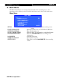
B.
Main Menu
C.
Recording Log Menu
D.
PTZ Menu
E.
Recording Menu
F.
Event Menu
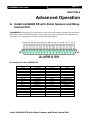
Advanced Operation
A.
Install
RX with Alarm Sensors and Relay Control Port
B.
Install
RX with Tamper Circuit and External Resistors
C.
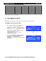
Throughput Control
D.
Event Handling
E.
Event Action
F.
Password
G.
Built-In Web Server
H.
Backup to CD / DVD / USB Flash
I.
Connection with PTZ cameras
J.
Panel Key Lock
K.
Time Synchronization
L.
Import and Export
M.
RX-SE setting
N.
User account
O.
External Keyboard
15
15
18
21
31
40
50
59
59
62
65
65
66
88
90
91
91
97
97
98
100
101
123
138
139
142
145
148
149
150
152
154
156
APPENDIX A
158
APPENDIX B
159
Safety Instruction
Limited Warranty
158
159
APPENDIX C
160
APPENDIX D
164
APPENDIX E
165
APPENDIX F
168
APPENDIX G
169
APPENDIX H
172
sureLINK Technology
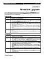
Firmware Upgrade
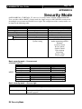
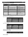
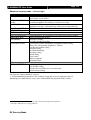
Security Mode
General Terms Discussion
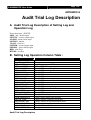
Audit Trial Log Description
A.
Audit Trial Log Description of Setting Log and Operation Log
B.
Setting Log Operation Column Table :
C.
Operation Log Operation Column Table :
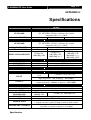
Specifications
160
164
165
168
169
169
169
171
172
User Guide
Page 1
SECTION 1
Introduction
A. Introduction
RX Series Video Recording Server operates with its revolutionary multi-rate
video coder to fulfill the highest video coding requirements for simultaneous transmission and
RX can be performed in low and
recording. Seamless video transmission by
medium bandwidth communication networks including ADSL, ISDN and PSTN; whilst
DVD-quality videos can be transmitted through LAN and recorded into local hard drive with
optimum speed at 50/60fps at D1 resolution. Real time recording rate of up to 200/240fps on
all video channels can also be achieved at CIF resolution.
RX provides professional and real life security control of premises with its
sophisticated event management scheme. It responses to a wide range of events triggered by
external alarm sensor, video motion, power interruption and tamper. There is an arm/disarm
control for the event management mechanism. Every external alarm input is configurable with
an individual entry/exit delay, fire zone and tamper detection setting. Various actions like
sending video back to a designated receiving PC, video recording, email notification, etc. can
be performed.
RX can also keep a comprehensive log of the events for audit trail.
RX is designed to fully comply with the British Standard BS 8418:2003,
providing professional remote monitoring and visual alarm verification solution to central
monitoring station.
With a built-in DVD-writer, video footage stored inside
RX can be easily
extracted for evidential purposes. Recorded video can be backed up in CD/DVD and played
back in any PC without any special software.
Introduction
User Guide
Page 2
B. Features
Hardware Feature
Video recording with rate up to 100/120fps (RX364), 200/240fps (RX368_V2 &
RX3616_V2)
Remote and standalone operations
Composite video output with OSD menu
SMAC-M multi-rate video coding technology
Real time video transmission
Up to 60fps (RX364), 120fps (RX368_V2 & RX3616_V2) over LAN for NTSC
Up to 50fps (RX364), 100fps (RX368_V2 & RX3616_V2) over LAN for PAL
Excellent picture resolution
Up to 720 x 480 pixels for NTSC
Up to 720 x 576 pixels for PAL
4 (RX364)/ 8 (RX368_V2) / 16 (RX3616_V2) video inputs with one video output
1 (RX364)/ 2 (RX368_V2 & RX3616_V2) audio inputs
1 Spot video output (RX368_V2 / RX3616_V2)
1 audio output and 1 public addressing (P.A.)output
4 relay switches and 16 alarm inputs
4 additional detection inputs
Removable hard disk
Built-in DVD writer
Functional Feature
sureLINK, support both static and dynamic IP
Sophisticated event management
System arm/disarm
Flexible connections: LAN, ADSL, PSTN, ISDN, mobile network, etc.
Triplex operation: simultaneous video monitoring, recording & playback
Video motion detection
Event-driven recording
Pre- & post-event video recording
Entry/exit zone configurable on all alarm inputs
Auto alarm dialback
Connection authentication
Compatibility with popular telemetry protocols
Single-site monitoring
Web-based video monitoring
Programmable video recording
Data retention
Mobile monitoring
Introduction
User Guide
Page 3
C. Removing the Packages
After removing the package, make sure you have the following items:
RX Video Recording Server with Built-in DVD Writer
Hard Disk Cartridge Accessories (Key x 2 and Screw x 4)
User Guide
Warranty Card
Registration Code Sheet
HDD Recommendation List
Software CD
Power Adaptor and Power Cord
Alarm Port Connector (37 Pins) & Alarm Port Cover
Resistors (1.2kΩ x 20, 6kΩ x 20)
Straight-through Ethernet Cable
D. Convention Used in This Manual
“ ”
{ }
[ ]
( )
: Buttons on the
RX video recording server front panel
: Hardware Items on the
RX video recording server besides buttons
: OSD menu or MS Windows menu
: Refers to other section or page
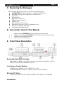
E. Front Panel Description
Removable Hard Disk Cartridge
{Key Lock} and {Key} are provided to lock the hard disk from unauthorized removing
and also be used to switch ON/OFF the system
Live Camera Control Buttons
For RX364 (1-4), RX368_V2 (1-8), RX3616_V2 (1-16)
“Camera Control” fast switch to a specific camera for local monitoring
Built-in DVD Writer
It allows user to back up video to CD-R, CD-RW or DVD (Max size of 4700 MB)
Introduction
User Guide
Page 4
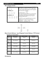
Screen Mode Control
For RX364
Full, Quad, 3 x 3, Hex screen mode:
The system will display one, four, eight, sixteen
screens decided on the button pressed. Sequential
mode will also be disabled.
For RX368_V2
Sequential mode**:
The sequential button enables the sequential page
mode of live monitoring. In sequential mode,
screen mode can be changed by pressing the
sequential button again.
For RX3616_V2
**In FULL screen sequential mode, the camera
sequence can be set on user’s preference.
(Main Menu --- Setup --- Video --- Local
monitoring --- Sequential Cams)
Menu Control Buttons / Local Playback Control Buttons / PTZ Control
Summary of Control Button
Buttons
Introduction
Menu Mode
Playback Mode
PTZ Mode
Cursor Up
Pause
Tilt Up
Cursor Down
Stop
Tilt Down
Cursor Left
Rewind
Pan Left
Cursor Right
Forward
Pan Right
Enter
Play
Zoom In
Pervious Page
Back/Stop
Zoom Out
User Guide
Page 5
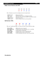
Mode Control Buttons and LED
These 5 buttons are used for switching between the control modes
“Event” button
“Rec” button
“Live” button
“Search” button
“Menu” button
:
:
:
:
:
Pop up event menu
Enable/disable normal or scheduled recording
View live video at any time and PTZ control in live mode
Playback log menu
System settings and other system operations
Notification LEDs
There are 5 notification LEDs, 2 red colors and 3 blue colors from left to right.
{Event LED}
{Recording LED}
{Live LED}
{Search LED}
{Menu LED}
{Power LED}
Introduction
:
:
:
:
:
:
Blinks when event is triggered
Is ON when the video recording server is recording
Is ON during live monitoring
Is ON when the system is in playback mode
Is ON when the system is in menu mode
Is ON continuously when the system is powered up
User Guide
Page 6
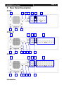
F. Rear Panel Description
RX364:
10
9
6
8
5
4
3
1
11
3
12
2
7
RX368_V2
10
9
8
7
6
5
4
2
1
RX3616_V2
10
9
11
8
Introduction
7
6
5
4
3
12
1
2
User Guide
Page 7
1.
Video Output Connectors
A composite video signal with 1V p-p is output from this connector
PAL/CCIR format with 625 lines, 25 frames per second
NTSC/EIA format with 525 lines, 30 frames per second
2.
Video Input Connector
{Standard BNC connectors} for video source input
A composite video source from camera should be supplied to these connectors
CH1 – CH4 (RX364)
CH1 – CH8 (RX368_V2)
CH1 – CH16 (RX3616_V2)
3.
Audio In/Out Port
{Audio In} : Connect audio input device (e.g. microphone) with RCA jack to
RX video recording server for recording. (Only 1 {Audio In} for RX364)
{Audio Out}: Connect audio output device (e.g. speaker) with RCA jack to
RX video recording server and generate output audio signal
{Audio PA} : Connect audio output device (e.g. speaker) to
RX video
recording server and generate audio signal to facilitate remote public addressing
4.
Ethernet Socket (10/100 Base-T)
This socket is used for connecting
RX to the corporate computer network
(e.g. LAN)
This socket includes {COL LED} and {LINK LED}
{COL LED} : When ON, indicates that collision is occurring on the network
{LINK LED} : When ON, indicates that
RX is connecting to the network
and ready to function
5. USB
For support firmware upgrade, setting import/export, USB modem and footage backup.
6. RS 232 (Modem) Port
A {DB-9 Male Connector} of DTE format, capable for connecting to DCE such as
modem, ISDN terminal adapter
Introduction
Pin number
Definition
Direction
1
2
3
4
5
6
7
8
9
CD
RXD
TXD
DTR
GND
DSR
RTS
CTS
Input
Input
Output
Output
–––
Input
Output
Input
–––
User Guide
7.
8.
9.
Page 8
RS 485 In/Out Port
{In}: 2-way terminal block for connecting a keyboard controller to
video recording server in order to control a PTZ camera
{Out}: 2-way terminal block for connecting a PTZ camera
Relay Out / Alarm In Port
4 relay (also call switch) outputs
16 alarm inputs
All alarm ports are NC/NO type and none/SEOL/DEOL tamper type input
All relay ports are latching/push-button type output
Power
Connect power supply (12V DC) to
10. Switch
Switch on or off the
RX video recording server
RX video recording server
11. VGA output (Optional)
Standard VGA connector
RX368_V2 / RX3616_V2 only
12. Spot Output
A composite video signal with 1V p-p is output from this connector
RX368_V2 / RX3616_V2 only
Introduction
RX
User Guide
Page 9
SECTION 2
Hard Disk Installation,
Formatting and Scanning
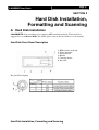
A. Hard Disk Installation
RX video recording server supports ATA standard hard disk. The hard disk is
suggested to set in Master Mode. For details please refer to the hard disk case or its manual.
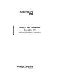
Hard Disk Front Panel Description
1. HDD activity indicator
2. Power indicator
3. Active-handle
4. Handle
5. Cartridge frame
6. Key lock
Key Lock Description
Hard Disk Installation, Formatting and Scanning
User Guide
Page 10
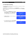
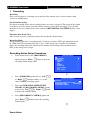
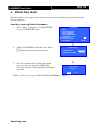
Installation Procedure
RX MUST be shut down before installing / uninstalling hard disk
button, select [SHUT DOWN] option and press “Enter”
1.
Press “Menu”
2.
[SHUT DOWN] menu will pop up and select [SHUT DOWN] option and press “Enter”
button.
3.
Select [YES] and press “Enter”
button to confirm the shut down and wait for the message
[IT IS NOW SAFE TO TURN OFF RX].
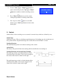
4.
Pull the active-handle outwards. Then use the
bundled key provided and insert into the
keyhole. Turn the key anti-clockwise (position
C), then you can pull out the handle.
5.
Pull the handle outwards to remove the carrier
body away from the cartridge frame.
6.
Push the release latch to slide the top cover
backwards and remove.
7.
Insert the DC power cable and IDE cable on the
HDD
Hard Disk Installation, Formatting and Scanning
button.
User Guide
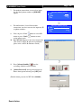
8.
Position the HDD into carrier body and secure
the HDD using the four screws provided.
9.
Slide the top cover back to the carrier body by
sliding forward to secure.
10. Slide the carrier body back into the cartridge
frame and push carrier body further into
cartridge frame until fully inserted.
11. Pull the active-handle outwards, then use the
bundled key and insert into the keyhole, turning
the key clockwise (position A) to secure the
handle.
Hard Disk Installation, Formatting and Scanning
Page 11
User Guide
Page 12
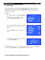
B. Hard Disk Formatting
Formatting a hard disk will erase all data in the hard disk. When it is reconstructed, it is readable
by
RX video recording server.
Formatting will be used if the hard disk format is NOT
RX video recording server
recognized. Usually, it is a new hard disk, or a hard disk which has not been used by
RX video recording server.
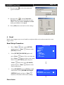
Procedure
1.
After starting up
RX video recording
server, OSD menu will pop up [INCORRECT
DISK FORMAT] menu. Select [YES] option and
press “Enter”
2.
INCORRECT DISK FORMAT
FORMAT NOW ?
button to format the hard disk.
YES
[FORMAT DISK] message board will pop up to
show about the status
NO
FORMAT DISK
\ FORMATTING 90%
3.
After finishing format process, [SCAN DISK]
processing board will pop up to show the scanning
status. The video recording server will restart.
SCAN DISK
\
Hard Disk Installation, Formatting and Scanning
SCANNING
90%
User Guide
Page 13
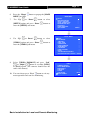
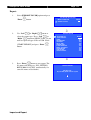
Manual Formatting
It will be used if user wants to format the hard disk so as to have a clean recording space and
redeem the file allocation.
1.
Press
“Menu”
button,
select
[SCAN/FORMAT DISK] option and press
“Enter”
button to enter [SCAN/FORAMAT
DISK] sub menu.
2.
Select [FORMAT] option press “Enter”
button
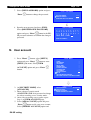
3.
Select [YES] option and press “Enter”
button
and [FORMAT DISK] board will pop up to
show about hard disk format processing status
4.
MAIN MENU
SETUP
FOOTAGE BACKUP
SWITCH CONTROL
SCAN / FORMAT DISK
TRANSMITTER INFO
LOCK KEYS
USER LOG-IN/OUT
SHUT DOWN
...
...
...
...
...
...
...
ENTER
SCAN / FORMAT DISK
DEVICE
LOCAL
START TIME
22:35 20/06/06
END TIME
10:07 15/11/06
MASTER MODEL NO
XXX
MASTER SERIAL NO
XXXX
MASTER CAPACITY
400GB
SLAVE MODEL NO
N/A
SLAVE SERIAL NO
SLAVE CAPACITY
DISK USAGE
52%
SCAN DISK
ENTER
FORMAT DISK
ENTER
Press “Enter”
button to restart video
recording server when [FORMAT FINISHED]
message board pops up.
FORMAT DISK
ALL DATA IN DISK
WILL BE ERASED ,
SURE TO PROCEED ?
YES
NO
FORMAT
FORMAT FINISHED ,
SYSTEM WILL RESTART NOW
OK
Note :
Select [DEVICE] in scan/format disk menu and press “Left”
or “Right”
button to
set [RX-SE1] option. Choose [FORMAT DISK] and select [YES]. The RX-SE1 will be
formatted
Hard Disk Installation, Formatting and Scanning
User Guide
Page 14
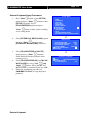
C. Scan Disk
It is a hard disk maintenance function which is similar to Scan Disk function provided by the
Operating System of your personal computer.
RX video recording server provides
this function in an attempt to rescue the hard disk when errors are found, and to enhance its
performance and reliability.
Procedure
1.
Press “Menu”
button, select [SCAN/FORMAT
MAIN MENU
DISK] option and press “Enter”
button to
enter [SCAN/FORAMT DISK] sub menu.
SETUP
FOOTAGE BACKUP
SWITCH CONTROL
SCAN / FORMAT DISK
TRANSMITTER INFO
LOCK KEYS
USER LOG-IN/OUT
SHUT DOWN
There is information about the hard disk. If not,
please check that the hard disk is installed
properly.
SCAN / FORMAT DISK
DEVICE
LOCAL
START TIME
22:35 20/06/06
END TIME
10:07 15/11/06
MASTER MODEL NO
XXX
MASTER SERIAL NO
XXXX
MASTER CAPACITY
400GB
SLAVE MODEL NO
N/A
SLAVE SERIAL NO
SLAVE CAPACITY
DISK USAGE
52%
SCAN DISK
ENTER
FORMAT DISK
ENTER
2.
Select [SCANDISK] option press “Enter”
button.
3.
Select [YES] option and press “Enter”
to start the [SCANDISK] process.
...
...
...
...
...
...
...
ENTER
button
SCAN DISK
ALL RECORDING WILL STOP
DURING SCANDISK
SURE TO PROCEED ?
YES
NO
Note :
Select [DEVICE] in main menu and press “Left”
or “Right”
button to set [RX-SE1]
option. Choose [SCAN DISK] and select [YES]. The RX-SE1 will be scanned.
Hard Disk Installation, Formatting and Scanning
User Guide
Page 15
SECTION 3
Basic Installation for Local and
Remote Monitoring
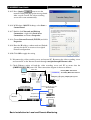
A.
RX Setup for Local CCTV Monitor
Connection Topology
VIDEO OUT: Connect to
monitor with RG59 cable
VIDEO IN: Connect to
and BNC connector
cameras with RG59 cable
and BNC connector
RG59 cable
CCTV
Monitor
RX
RG59 cable
Cameras
Power Adapter
*Note: SPOT OUT only for RX368_V2 / RX3616_V2
Equipment
RX Video recording server
Cameras
Video Cables (RG-59) with BNC Header
CCTV Monitor
Basic Installation for Local and Remote Monitoring
User Guide
Page 16
Setup Procedure
1.
Connect cameras to
RX {Video Input} with RG59 cable and BNC connector.
Note: The camera system is either NTSC or PAL and all cameras must have the SAME
system format.
RX {Video Output} with RG59 cable and BNC
2.
Connect CCTV monitor to
connector.
3.
Install and use the bundled key to lock the {Hard Disk Rack} with hard disk to the
RX.
Note: If there is no hard disk installed, Recording and Playback are not functional
RX.
4.
Plug in the power adapter (12V DC) to
5.
Turn on the power of
RX, camera and monitor. Check the {Power LED}
which is lit up in blue color continuously at
RX front panel after power on.
After several seconds, live video appears on the CCTV monitor as follows:
Note: Please go through the following steps (6-10) if CCTV monitor does not show video clearly
Basic Installation for Local and Remote Monitoring
User Guide
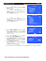
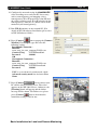
6.
Press the “Menu”
MENU] on OSD.
7.
Use “Up”
Page 17
button to pop up the [MAIN
or “Down”
button to select
[SETUP] option and press “Enter”
enter the [SETUP] sub-menu.
button to
MAIN MENU
SETUP
FOOTAGE BACKUP
SWITCH CONTROL
SCAN / FORMAT DISK
TRANSMITTER INFO
LOCK KEYS
USER LOG-IN/OUT
SHUT DOWN
...
...
...
...
...
...
...
ENTER
SETUP MENU
8.
Use “Up”
or Down”
button to select
[VIDEO] option and press “Enter”
enter the [VIDEO] sub-menu.
9.
button to
Select [VIDEO FORMAT] and press “Left”
or “Right”
button to set either [NTSC]
or [PAL] option. (All cameras should have the
same video format).
10. You can always press “Live” button to exit any
menu operation and start live monitoring.
Basic Installation for Local and Remote Monitoring
VIDEO
RECORDING
SWITCHES
DATE / TIME
CONNECTION
EVENT HANDLER
TRANSMITTER
PASSWORD
USER ACCOUNT
RX-SE
SETTING IMPORT/EXPORT
RESTORE FACTORY SETTING
...
...
...
...
...
...
...
...
...
...
...
ENTER
VIDEO
CAMERA SETTING
LOCAL MONITORING
BRIGHTNESS
CONTRAST
COLOR
OSD COLOR
VIDEO FORMAT
...
...
...
...
...
BLUE
PAL
User Guide
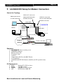
B.
Page 18
RX Setup for VGA Monitor
Connection Topology
VIDEO IN: Connect to
VGA
Monitor
cameras with RG59 cable
and BNC connector
VGA cable
RX
RG59 cable
Cameras
Power Adapter
*Note: VGA OUTPUT only for RX368_V2 / RX3616_V2 with optional VGA module
installed .
Equipment
RX Video Recording Server
Cameras
VGA cable
VGA Monitor (support 1024x768 / 1280x1024 / 60Hz / 75Hz)
Basic Installation for Local and Remote Monitoring
User Guide
Page 19
Setup Procedure
1.
Connect cameras to
RX {Video Input} with RG59 cable and BNC connector.
Note: The camera system is either NTSC or PAL and all cameras must have the SAME
system format.
RX {VGA Output} with VGA Cable.
2.
Connect VGA monitor to
3.
Install and use the bundled key to lock the {Hard Disk Rack} with hard disk to the
RX.
Note: If there is no hard disk installed, Recording and Playback are not functional
RX.
4.
Plug in the power adapter (12V DC) to
5.
Turn on the power of
RX, camera and monitor. Check the {Power LED}
which is lit up in blue color continuously at
RX front panel after power on.
After several seconds, live video appears on the VGA monitor as follows:
Note: If video does not shown on VGA monitor correctly, please check the VGA monitor support
RX default VGA setting (1024x768 resolution, 60Hz). If VGA monitoring does not support
default VGA setting, please use WX-30 reception software to select proper settings after setup
network connection.
Basic Installation for Local and Remote Monitoring
User Guide
Page 20
MAIN MENU
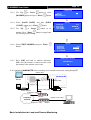
6.
Press the “Menu”
MENU] on OSD.
7.
Use “Up”
button to pop up the [MAIN
or “Down”
button to select
[SETUP] option and press “Enter”
enter the [SETUP] sub-menu.
button to
SETUP
FOOTAGE BACKUP
SWITCH CONTROL
SCAN / FORMAT DISK
TRANSMITTER INFO
LOCK KEYS
USER LOG-IN/OUT
SHUT DOWN
...
...
...
...
...
...
...
ENTER
SETUP MENU
8.
Use “Up”
or Down”
button to select
[VIDEO] option and press “Enter”
enter the [VIDEO] sub-menu.
button to
VIDEO
RECORDING
SWITCHES
DATE / TIME
CONNECTION
EVENT HANDLER
TRANSMITTER
PASSWORD
USER ACCOUNT
RX-SE
SETTING IMPORT/EXPORT
RESTORE FACTORY SETTING
...
...
...
...
...
...
...
...
...
...
...
ENTER
VIDEO
9.
Select [VIDEO FORMAT] and press “Left”
or “Right”
button to set either [NTSC]
or [PAL] option. (All cameras should have the
same video format).
10. Select [VGA SETTING] and press “Enter”
button to enter [VGA SETTING] menu.
or
11. Select [RESOLUTION] and press “Left”
“Right”
button to set VGA resolution
according to the VGA monitoring
12. Select [FREQUENCY] and press “Left”
or
“Right”
button to set VGA frequency
according to the VGA monitoring
13. You can always press “Live”
CAMERA SETTING
LOCAL MONITORING
SPOT VIDEO
VGA SETTING
OSD COLOR
VIDEO FORMAT
...
...
...
...
BLUE
PAL
VGA SETTING
VGA OUT
SPOT VGA OUT
RESOLUTION
FREQUENCY
...
...
1024X768
75HZ
button to exit any menu operation and start live monitoring.
Basic Installation for Local and Remote Monitoring
User Guide
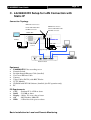
C.
Page 21
RX Setup for LAN Connection with
Static IP
Connection Topology
VIDEO OUT: Connect to
monitor with RG59 cable
VIDEO IN: Connect to
cameras with RG59 cable
and BNC connector
and BNC connector
RG59 cable
CCTV
Monitor
RX
RG59 cable
Ethernet
Socket
Power Adapter
Cameras
Straight-through Ethernet cable
Network switch
Equipment
RX Video recording server
Network Switch
Straight-through Ethernet Cable (bundled)
Cross-over Ethernet Cable
Cameras
Video Cables (RG-59) with BNC Header
CCTV Monitor
CD ROM with WX-30 Software (bundled) (for PC operation only)
PC
PC Requirements
CPU
: Pentium IV 2.4 GHz or above
RAM : 512 MB or above
Display : 1024 x 768, true color or better
OS
: MS Windows 2000, XP
HDD
: 1GB of free disk space or above
Basic Installation for Local and Remote Monitoring
User Guide
Page 22
Setup Procedure
1.
Connect cameras to
RX {Video Input} with RG59 cable and BNC connector.
Note: The cameras system is either NTSC or PAL and all cameras must have the SAME
system format.
RX {Video Output} with RG59 cable and BNC
2.
Connect CCTV monitor to
connector.
3.
Install and use the bundled key to lock the {Hard Disk Rack} with hard disk to the
RX.
Note: If there is no hard disk installed, Recording and Playback are not functional
RX.
4.
Connect the power adapter (12V DC) to the
5.
Turn on the power of
RX, camera and monitor. Check the {Power LED}
which is lit up in blue color continuously at
RX front panel after power on.
After several seconds, live video appears on the CCTV monitor as follows:
Note: Please go through the following steps (6-10) if the video of CCTV monitor does not show
clearly.
Basic Installation for Local and Remote Monitoring
User Guide
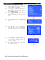
6.
Press the “Menu”
MENU] on OSD.
7.
Use “Up”
Page 23
SETUP MENU
button to pop up the [MAIN
or “Down”
VIDEO
RECORDING
SWITCHES
DATE / TIME
CONNECTION
EVENT HANDLER
TRANSMITTER
PASSWORD
USER ACCOUNT
RX-SE
SETTING IMPORT / EXPORT
RESTORE FACTORY SETTING
button to select
[SETUP] option and press “Enter”
enter the [SETUP] sub-menu.
button to
8.
Select [VIDEO] option and press “Enter”
to enter the [VIDEO] sub-menu
9.
Select [VIDEO FORMAT] and press “Left”
button to set either [NTSC] or
or “Right”
[PAL] option. (All cameras should have the same
video format).
button
VIDEO
CAMERA SETTING
LOCAL MONITORING
SPOT VIDEO
VGA SETTING
OSD COLOR
VIDEO FORMAT
10. You can always press “Live” button to exit any
menu operation and start live monitoring.
...
...
...
...
BLUE
PAL
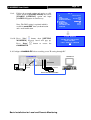
RX video recording server IP setting
11. Configure
RX video recording server IP through CCTV monitor, please go to step 11a.
RX video recording server IP through PC, please go to step 11b.
Setup
Setup
11.a.1
...
...
...
...
...
...
...
...
...
...
...
ENTER
RX video recording server IP setting through CCTV Monitor
Configure
RX
RG59 cable
192.168.0.2
Ethernet
Power Adapter
Socket
RG59 cable
CCTV
Cameras
Basic Installation for Local and Remote Monitoring
Monitor
User Guide
Page 24
11.a.2
Press the “Menu” button such that the OSD
main menu opens on the monitor.
11.a.3
Use “Up”
11.a.4
[SETUP] option and press “Enter”
button
to enter [SETUP] sub menu.
Select [CONNECTION] option and press
“Enter”
menu.
11.a.5
11.a.6
11.a.7
or “Down”
button to enter connection setting
Select [TCP/IP] option and press “Enter”
button
Select [IP] option and press “Enter”
button. IP address consists of four fields.
Each field can assign a number from 0 to 255
Use “Left”
or “Right”
select field and use “Up”
button to set number.
11.a.8
button to select
SETUP MENU
VIDEO
RECORDING
SWITCHES
DATE / TIME
CONNECTION
EVENT HANDLER
TRANSMITTER
PASSWORD
USER ACCOUNT
RX-SE
SETTING IMPORT / EXPORT
RESTORE FACTORY SETTING
CONNECTION
TCP / IP
MODEM
THROUGHPUT
…
…
…
TCP / IP
IP
PORT
SUBNET MASK
ENABLE GATEWAY
GATEWAY
ENABLE DNS
PRIMARY DNS
SECONDARY DNS
SURELINK
192.168.0.2
1024
255.255.255.0
NO
0.0.0.0
NO
0.0.0.0
0.0.0.0
…
button to
or “Down”
Press “Enter”
button to save the change
and return previous menu.
Basic Installation for Local and Remote Monitoring
...
...
...
...
...
...
...
...
...
...
...
ENTER
IP
IP : 210. 17.139.145
User Guide
11.a.9
Page 25
Follow the network setting and assign a valid
subnet mask to [SUBNET MASK] and select
[ENABLE GATEWAY] option and input
[GATEWAY] option in similar way.
TCP / IP
IP
PORT
SUBNET MASK
ENABLE GATEWAY
GATEWAY
ENABLE DNS
PRIMARY DNS
SECONDARY DNS
SURELINK
Note: The DNS setting is optional which is
useful for sureLINK, time synchronization
and e-mail notification.
SETTING MODIFIED
button, then [SETTING
11.a.10 Press “Live”
MODIFIED] message board will pop up.
Press “Enter”
RX.
11.b Configure
210.17.139.145
1024
255.255.255.0
YES
210.17.139.1
NO
0.0.0.0
0.0.0.0
…
SETTING WILL TAKE EFFECT
AFTER RESTART ,
PRESS ENTER TO CONTINUE
OK
button to restart the
RX video recording server IP setting through PC
192.168.0.3
RX
192.168.0.2
Ethernet
Socket
RG59 cable
Cameras
Power Adapter
Cross-over Ethernet Cable
Basic Installation for Local and Remote Monitoring
User Guide
Page 26
11.b.1. In Windows 2000/XP desktop, select Start >
Control Panel
11.b.2. Double click Network and Dial-up Connections
> right click Local Area Connections and choose
Properties.
11.b.3. Choose Internet Protocol (TCP/IP) and click
Properties
11.b.4. Enter an IP address, subnet mask and Default
gateway. Note that IP address should be
“192.168.0.xx” except “192.168.0.2” which is
RX default IP address.
11.b.5. Enter the Preferred and Alternate DNS server,
if necessary.
11.b.6. Click OK to activate the new IP.
You have to confirm that IP address has been
correctly set on your computer. On your windows,
click start > run, type “cmd” at open field, press
OK button, type “ipconfig” on the DOS prompt
and you will see an IP set on your computer.
11.b.7. Connect the PC Ethernet socket to the video
recording server Ethernet socket at rear panel of
the video recording server with cross-over
Ethernet cable. Check if the {LINK LED} of the
video recording server is ON.
Basic Installation for Local and Remote Monitoring
10/100
LINK
BASE-T
COL
User Guide
11.b.8. Run WX-30 software which has been installed to
the PC. (For details of WX-30 software
installation, please refer to WX-30 Software
Guide)
11.b.9. Choose [Transmitter] [Registration] to
register the
RX video recording
server. User needs to input video recording server
serial number and registration code.
For example :
Serial No. : VTC12345
Registration Code : 1234567890
11.b.10. Press [Connect]
icon to pop up the [Connect
Window]. Type and select the following setting :
Phone/IP : 192.168.0.2
Connect Using: TCP/IP LAN
Password: 000000
IP (192.168.0.2) and Password (000000) are
default setting of
RX
If RX is set to advanced security mode, check
Advanced security mode box and enter User
Name
11.b.11. Press [Connect]
icon to connect your
PC to the video recording server. Live video is
shown on the WX-30 if success. Otherwise, the
[Warning] board will pop up and show you
failure message. For failure case, please press
[Connect]
icon to check that the connection
setting is valid or not.
Basic Installation for Local and Remote Monitoring
Page 27
User Guide
Page 28
11.b.12. Press [Transmitter Setup]
icon to show
RX configuration menu.
11.b.13. Select [Connection] and press [Network
Settings]
network setting.
icon to configure
11.b.14. Change the IP from 192.168.0.2 to
210.17.139.145 (for example). Gateway setting is
used for WAN. Primary and Secondary DNS
setting are used for sureLINK, time
synchronization or e-mail notification function.
11.b.15. Press [Apply]
icon to save the network
setting and the message board will pop up. After
several seconds, the video recording server will
restart automatically.
Basic Installation for Local and Remote Monitoring
User Guide
Page 29
11.b.16. In Windows 2000/XP desktop, select Start >
Control Panel
11.b.17. Double click Network and Dial-up Connections
> right click Local Area Connections and choose
Properties.
11.b.18. Choose Internet Protocol (TCP/IP) and click
Properties
11.b.19. Enter the IP address, subnet mask and Default
gateway for the PC to restore to its original
network configuration.
Note: The first 3 field of IP address should be
same as
RX video recording server IP
and gateway address. IP address is
“210.17.139.146” and gateway address is
“210.17.139.1” in this example.
11.b.20. Click OK to apply the settings
12. Disconnect the
RX video recording server and current PC. Reconnect the video
recording server and current PC to the LAN network through straight-through Ethernet
cable.
10/100
BASE-T
13. Check Ethernet socket of both
RX video recording server and PC to ensure that
the {GREEN LINK LED} turns ON. Then connection diagram is shown as below:
LINK
COL
RG59 cable
RX
CCTV
Monitor
210.17.139.146
210.17.139.145
RG59 cable
Ethernet
Power Adapter
Cam eras
Socket
210.17.139.147
Straight-through Ethernet cable
Network switch
Basic Installation for Local and Remote Monitoring
User Guide
14. Run WX-30 software at any local network PC. (For
details of WX-30 software installation, please refer
to WX-30 Software Guide)
15. Press [Connect]
icon to pop up the [Connect
Window]. For example, type and select the
following setting :
Phone/IP : 210.17.139.153
Connect Using: TCP/IP LAN
Password: 000000
If RX is set to advanced security mode, check
Advanced security mode box and enter User
Name
icon to connect your PC
16. Press [Connect]
and the video recording server. The video appears
on the WX-30 if success. Otherwise, the [Warning]
board will pop up and failure message will be
shown. For failure case, please press [Connect]
icon to check that the connection setting is valid or
not.
Basic Installation for Local and Remote Monitoring
Page 30
User Guide
D.
Page 31
RX Setup for Broadband or Narrowband
Internet Connection with Static IP
Connection Topology
V ID E O O U T : C o n n e c t to
m o nito r w ith R G 5 9 c a b le a n d
V ID E O IN : C o n n e c t to
B N C c o n n e c to r
c a m e ra s w ith R G 5 9 c a b le
a n d B N C c o n n e c to r
R G 5 9 c a b le
RX
CCTV
M o n ito r
R G 5 9 c a b le
E th e rn e t
P o w e r A d a p te r
R o u te r/G a te w a y
In te r n e t
C a m e ra s
S ocket
Stra ig h t-th ro u g h E th e rn e t c a b le
Stra ig h t-th ro u g h E th e rn e t c a b le
R o u te r/G a te w a y
Remark for Internet Connection Definition
Broadband : Connection speed is equals to 128kbps or above, e.g. ADSL, DSL.
Narrowband : Connection speed is below 128kbps, e.g. dial up network, GPRS
Equipment
RX Video recording server
Network Switch, Router/Gateway
Straight-through Ethernet Cable (bundled)
Cross-over Ethernet Cable
Cameras, Video Cables (RG-59) with BNC Header
CCTV Monitor
CD ROM with WX-30 Software (bundled) (for PC operation only)
PC
PC Requirements
CPU
: Pentium IV 2.4 GHz or above
RAM
: 512 MB or above
Display : 1024x768, true color or better
OS
: MS Windows 2000, XP
HDD
: 1 GB of free disk space or above
Basic Installation for Local and Remote Monitoring
User Guide
Page 32
Setup Procedure
1. Connect cameras to
RX {Video Input} with RG59 cable and BNC connector.
Note: The camera system is either NTSC or PAL and all cameras must have the SAME
system format.
2. Connect CCTV monitor to
connector.
RX {Video Output} with RG59 cable and BNC
3. Install and use the bundled key to lock the {Hard Disk Rack} with hard disk to the
RX.
Note: If there is no hard disk installed, Recording and Playback are not functional.
4. Connect the power adapter (12V DC) to the
RX.
5. Turn on the power of
RX, camera and monitor. Check the {Power LED} ,
which is lit up in blue color continuously at
RX front panel after power on.
After several seconds, live video appears on the CCTV monitor as follows:
Note: Please go through the following steps (6-10) if the video of CCTV monitor does not show
clearly.
Basic Installation for Local and Remote Monitoring
User Guide
6. Press the “Menu”
MENU] on OSD.
7. Use “Up”
Page 33
button to pop up the [MAIN
or “Down”
button to select
[SETUP] option and press “Enter”
enter the [SETUP] sub-menu.
8. Select [VIDEO] option and press “Enter”
to enter the [VIDEO] sub-menu.
button to
button
9. Select [VIDEO FORMAT] and press “Left”
or “Right”
button to set either [NTSC] or
[PAL] option. (All cameras should have the same
video format).
10. You can always press “Live” button to exit any
menu operation and start live monitoring.
MAIN MENU
SETUP
FOOTAGE BACKUP
SWITCH CONTROL
SCAN / FORMAT DISK
TRANSMITTER INFO
LOCK KEYS
USER LOG-IN/OUT
SHUT DOWN
...
...
...
...
...
...
...
ENTER
SETUP MENU
VIDEO
RECORDING
SWITCHES
DATE / TIME
CONNECTION
EVENT HANDLER
TRANSMITTER
PASSWORD
USER ACCOUNT
RX-SE
SETTING IMPORT/EXPORT
RESTORE FACTORY SETTING
...
...
...
...
...
...
...
...
...
...
...
ENTER
VIDEO
CAMERA SETTING
LOCAL MONITORING
SPOT VIDEO
VGA SETTING
OSD COLOR
VIDEO FORMAT
...
...
...
...
BLUE
PAL
RX video recording server IP through CCTV monitor, please go to step 11a.
RX video recording server IP through PC, please go to step 11b.
Setup
Setup
11.a Configure
RX video recording server IP setting through CCTV Monitor
RG59 cable
RX
192.168.0.2
Ethernet
Socket
RG59 cable
CCTV
Cameras
Power Adapter
Basic Installation for Local and Remote Monitoring
Monitor
User Guide
Page 34
11.a.1 Press the “Menu” button such that the OSD
main menu pops up on the monitor.
11.a.2 Use “Up”
or “Down”
button to select
[SETUP] option and press “Enter”
button.
11.a.3 Select [CONNECTION] option and press
“Enter”
button
SETUP MENU
VIDEO
RECORDING
SWITCHES
DATE / TIME
CONNECTION
EVENT HANDLER
TRANSMITTER
PASSWORD
USER ACCOUNT
RX-SE
SETTING IMPORT/EXPORT
RESTORE FACTORY SETTING
11.a.4 Select [TCP/IP] option and press “Enter”
button
CONNECTION
TCP / IP
MODEM
THROUGHPUT
button. IP
11.a.5 Select [IP] option and press “Enter”
address consists of four fields. Each field can
assign a number from 0 to 255.
11.a.6 Use “Left”
or “Right”
field and use “Up”
number.
button to select
or “Down”
...
...
...
...
...
...
...
...
...
...
...
ENTER
…
…
…
TCP / IP
IP
PORT
SUBNET MASK
ENABLE GATEWAY
GATEWAY
ENABLE DNS
PRIMARY DNS
SECONDARY DNS
SURELINK
192.168.0.2
1024
255.255.255.0
NO
0.0.0.0
NO
0.0.0.0
0.0.0.0
…
button to set
IP
11.a.7 Press “Enter”
button to save the change and
return previous menu.
IP : 210. 17.139.145
11.a.8 Follow the network setting and assign valid
subnet mask to [SUBNET MASK] and select
[ENABLE GATEWAY] option and input
[GATEWAY] option in similar way.
11.a.9 Set the Gateway value (for example) to
210.17.139.1
Note: The DNS setting is optional which is useful
for sureLINK, time synchronization or e-mail
notification function.
TCP / IP
IP
PORT
SUBNET MASK
ENABLE GATEWAY
GATEWAY
ENABLE DNS
PRIMARY DNS
SECONDARY DNS
SURELINK
11.a.10Press “Live” button and [SETTING
MODIFIED] message board will pop up.
RX video recording server IP
11.b Configure
setting through PC
Basic Installation for Local and Remote Monitoring
210.17.139.145
1024
255.255.255.0
YES
210.17.139.1
NO
0.0.0.0
0.0.0.0
…
SETTING MODIFIED
SETTING WILL TAKE EFFECT
AFTER RESTART ,
PRESS ENTER TO CONTINUE
OK
User Guide
Page 35
192.168.0.3
RX
RG59 cable
192.168.0.2
Ethernet
Cameras
Socket
Power Adapter
Cross-over Ethernet Cable
11.b.1. In Windows 2000/XP desktop, select Start >
Control Panel
click
Network
and
Dial-up
11.b.2. Double
Connections > right click Local Area
Connections and choose Properties.
11.b.3. Choose Internet Protocol (TCP/IP) and click
Properties
11.b.4. Enter an IP address, subnet mask and Default
gateway. Note that IP address should be
“192.168.0.xx” except “192.168.0.2” which is
RX default IP address.
11.b.5. Enter the Preferred and Alternate DNS server, if
necessary.
11.b.6. Click OK to activate the new IP.
Note: You have to confirm that IP address has
been correctly set on your computer. On your
windows, click start > run, type “cmd” at Open
field and press OK button, then type “ipconfig”
on the DOS prompt, you will see an IP set on
your computer.
Basic Installation for Local and Remote Monitoring
User Guide
11.b.7. Connect the PC Ethernet socket to the video
recording server Ethernet socket at rear panel of
the video recording server with cross-over
Ethernet cable. Check if the {LINK LED} of the
video recording server is ON.
11.b.8. Run WX-30 software which has been installed to
the PC. (For details of WX-30 software
installation, please refer to WX-30 Software
Guide)
[Registration] to
11.b.9. Choose [Transmitter]
register the
RX video recording
server. User needs to input video recording
server serial number and registration code.
For example :
Serial No. : VTC12345
Registration Code : 1234567890
11.b.10. Press [Connect]
icon to pop up the
[Connect Window]. Type and select the
following setting :
For Broadband Connection :
Phone/IP
: 192.168.0.2
Connect Using
: TCP/IP Broadband
Password
: 000000
OR
For Narrowband Connection :
Phone/IP
: 192.168.0.2
Connect Using
: TCP/IP Narrowband
Password
: 000000
IP (192.168.0.2) and Password (000000)
If RX is set to advanced security mode, check
Basic Installation for Local and Remote Monitoring
Page 36
10/100
LINK
BASE-T
COL
User Guide
Page 37
Advanced security mode box and enter User
Name
11.b.11. Press [Connect]
icon to connect
your PC and the video recording server. The
video appears on the WX-30 if success.
Otherwise, the [Warning] board will pop up and
show you failure message. For failure case,
please press [Connect]
icon to check that
the connection setting is valid or not.
11.b.12. Press [Transmitter setup]
icon to show
RX configuration menu.
11.b.13. Select
[Connection]
Settings]
network setting.
and
press
[Network
icon to configure
11.b.14. Change the IP from 192.168.0.2 to (for example)
210.17.139.145
and
Gateway
setting
210.17.139.1 (for example). Primary and
Secondary DNS setting (for example) are used
for sureLINK, time synchronization** or e-mail
notification function **.
11.b.15. Press [Apply]
icon to save the
network setting and the message board will pop
up. After several seconds, the video recording
server will restart automatically.
Basic Installation for Local and Remote Monitoring
User Guide
Page 38
11.b.16. In Windows 2000/XP desktop, select Start >
Control Panel
11.b.17. Double
click
Network
and
Dial-up
Connections > right click Local Area
Connections and choose Properties.
11.b.18. Choose Internet Protocol (TCP/IP) and click
Properties
11.b.19. Enter the IP address, subnet mask and Default
gateway for the PC to restore to its original
network configuration.
11.b.20. Click OK to apply the setting
12. Disconnect the video recording server and current PC. Reconnect the video recording server
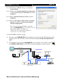
and current PC to the Internet network through straight-through Ethernet cable.
13. Check Ethernet socket of both the video recording server and PC to ensure that the
{GREEN LINK LED} turns ON. Then connection diagram is shown as follows:
10/100
LINK
RG59 cable
CCTV
RX
Monitor
210.17.139.145
Ethernet
Power Adapter
Socket
Cameras
RG59 cable
Straight-through Ethernet cable
Router/Gateway
211.134.139.9
210.17.139.1
Straight-through Ethernet cable
Internet
211.134.139.1
211.134.139.7
Router/Gateway
Basic Installation for Local and Remote Monitoring
BASE-T
COL
User Guide
14. Configure the network setting for
RX
video recording server and your PC if necessary,
such as router/gateway port mapping (select
router/gateway IP as IP provided by your ISP
and the video recording server IP as IP provided
by the router/gateway), firewall, etc. (Please refer
to the manual of your router/gateway.)
15. Run WX-30 software at any network PC. (For
details of WX-30 software installation, please
refer to WX-30 Software Guide)
icon to pop up the
16. Press [Connect]
[Connect Window]. For example, type and
select the following setting :
Broadband Connection :
Phone/IP
: 210.17.139.145
Connect Using
: TCP/IP Broadband
Password
: 000000
OR
Narrowband Connection :
Phone/IP
: 210.17.139.145
Connect Using
: TCP/IP Narrowband
Password
: 000000
If RX is set to advanced security mode, check
Advanced security mode box and enter User
Name
17. Press [Connect]
icon to connect your
PC and the video recording server. The video
appears on the WX-30 if success. Otherwise, the
[Warning] board will pop up and the failure
message will be shown. For failure case, please
press [Connect]
icon to check that the
connection setting is valid or not.
Basic Installation for Local and Remote Monitoring
Page 39
User Guide
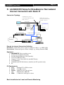
E.
Page 40
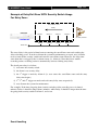
RX Setup for Broadband or Narrowband
Internet Connection with Dynamic IP
Connection Topology
V ID E O O U T: Co nn ect to
m o n ito r w ith R G 59 cab le
V ID E O IN : C o nn e ct to
a nd B N C co nne cto r
ca m e ra s w ith R G 59 ca b le
a nd B N C co nne cto r
R G 59 cable
RX
C C TV
M o n ito r
w w w.yo u r_s ite.yo u r_ co m p an y.te le eye.ne t
P o w e r Ad ap te r
E the rne t R G 59 cable
S o cke t
C a m e ra s
Stra ig h t-th rou gh E the rn et ca b le
R ou ter/G a tewa y
Stra ig h t-th rou gh Ethe rn et ca b le
In tern et
R ou ter/G atewa y
Remark for Internet Connection Definition
Broadband : Connection speed equals to 128kbps or above, e.g. ADSL, DSL.
Narrowband : Connection speed is below 128kbps, e.g. dial up network, GPRS
Equipment
RX Video recording server
Network Switch, Router/Gateway, ADSL Modem
Straight-through Ethernet Cable (bundled), Cross-over Ethernet Cable
Cameras, Video Cables (RG-59) with BNC Header, Monitor
CD ROM with WX-30 Software (bundled) (for PC operation only)
CCTV Monitor
PC
PC Requirements
CPU
: Pentium IV 2.4 GHz or above
RAM
: 512 MB or above
Display : 1024 x 768, true color or better
HDD
: 1 GB of free disk space or above
OS
: MS Windows 2000, XP
Basic Installation for Local and Remote Monitoring
User Guide
Page 41
Setup Procedure
1. Connect cameras to
RX {Video Input} with RG59 cable and BNC connector.
Note: The camera system is either NTSC or PAL and all cameras must have the SAME
system format.
2. Connect CCTV monitor to
connector.
RX {Video Output} with RG59 cable and BNC
3. Install and use the bundled key to lock the {Hard Disk Rack} with Hard disk to the
RX.
Note: If there is no hard disk installed, Recording and Playback are not functional.
4. Connect the power adapter (12V DC) to the
RX.
5. Turn on the power of
RX, camera and monitor. Check the {Power LED} ,
which is lit up in blue color continuously at
RX front panel after power on.
After several seconds, live video appears on the CCTV monitor as follows:
Note: Please go through the following steps (6-10) if the video of CCTV monitor does not show
clearly.
Basic Installation for Local and Remote Monitoring
User Guide
6. Press the “Menu”
MENU] on OSD.
7. Use “Up”
Page 42
button to pop up the [MAIN
or “Down”
button to select
[SETUP] option and press “Enter”
enter the [SETUP] sub-menu.
button to
8. Select [VIDEO] option and press “Enter”
button
9. Select [VIDEO FORMAT] and press “Left”
or “Right”
button to set either [NTSC] or
[PAL] option. (All cameras should have the same
video format).
10. You can always press “Live” button to exit any
menu operation and start live monitoring.
SETUP MENU
VIDEO
RECORDING
SWITCHES
DATE / TIME
CONNECTION
EVENT HANDLER
TRANSMITTER
PASSWORD
USER ACCOUNT
RX-SE
SETTING IMPORT/EXPORT
RESTORE FACTORY SETTING
...
...
...
...
...
...
...
...
...
...
...
ENTER
VIDEO
CAMERA SETTING
LOCAL MONITORING
SPOT VIDEO
VGA SETTING
OSD COLOR
VIDEO FORMAT
...
...
...
...
BLUE
PAL
RX video recording server IP through CCTV monitor, please go to step
Setup
11a.
Setup
RX video recording server IP through PC, please go to step 11b.
RX video recording server IP setting through CCTV Monitor
11.a Configure
RG59 cable
RX
192.168.0.2
RG59 cable
CCTV
Ethernet Socket
Cameras
Monitor
Power Adapter
11.a.1 Press the “Menu” button such that the OSD
main menu pops up on the monitor.
11.a.2 Use “Up”
or “Down”
button to select
[SETUP] option and press “Enter”
11.a.3 Select
“Enter”
[CONNECTION]
button
option
button.
and
press
SETUP MENU
VIDEO
RECORDING
SWITCHES
DATE / TIME
CONNECTION
EVENT HANDLER
TRANSMITTER
PASSWORD
USER ACCOUNT
RX-SE
SETTING IMPORT/EXPORT
RESTORE FACTORY SETTING
Basic Installation for Local and Remote Monitoring
...
...
...
...
...
...
...
...
...
...
...
ENTER
User Guide
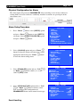
Page 43
CONNECTION
11.a.4
Select [TCP/IP] option and press “Enter”
button
11.a.5 Select [IP] option and press “Enter”
TCP / IP
MODEM
THROUGHPUT
button.
IP address consists of four fields. Each field can
assign a number from 0 to 255.
…
…
…
TCP / IP
IP
PORT
SUBNET MASK
ENABLE GATEWAY
GATEWAY
ENABLE DNS
PRIMARY DNS
SECONDARY DNS
SURELINK
192.168.0.2
1024
255.255.255.0
NO
0.0.0.0
NO
0.0.0.0
0.0.0.0
…
IP
11.a.6 Use “Left”
or “Right”
button to select
IP : 210. 17.139. 5
field and use “Up”
or “Down”
button to
set number. Set IP address (for example) to 210.17.139.5
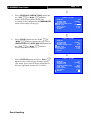
11.a.7 Press “Enter”
button to save the change and
return previous menu.
11.a.8 Follow the network setting and assign valid subnet
mask to [SUBNET MASK] and select [ENABLE
GATEWAY] option and input [GATEWAY]
option in similar way. Assign the Gateway (for
example) to 210.17.139.1
TCP / IP
IP
PORT
SUBNET MASK
ENABLE GATEWAY
GATEWAY
ENABLE DNS
PRIMARY DNS
SECONDARY DNS
SURELINK
210.17.139.5
1024
255.255.255.0
YES
210.17.139.1
NO
0.0.0.0
0.0.0.0
…
or
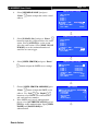
11.a.9 Select [ENABLE DNS] option Use “Left”
“Right”
button to select [YES] to enable DNS.
11.a.10 Assign the Primary DNS (for example) to 202.14.67.4
11.a.11 Assign the Secondary DNS (for example) to 202.14.67.14
11.a.12 Select [SURELINK] option from TCP/IP menu
and press “Enter”
button to enter the sub menu.
11.a.13 Select [ENABLED] option and press “Left”
or “Right”
button to set [YES] value
Basic Installation for Local and Remote Monitoring
SURELINK
ENABLED
SURELINK ADDRESS
REFRESH RATE
YES
www…..
1 MINS
User Guide
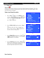
Page 44
11.a.14 Select [SURELINK ADDRESS] option
and press “Enter”
editing menu.
SURELINK ADDRESS
0 1
A B
K L
U V
CLEAR
button to sureLINK
There are two fields for assigning sureLINK
address
“www.your_site.your_company.TeleEye.net”
2 3
C D
M N
W X
END
WWW. _
4
E
O
Y
.
5 6 7 8 9
F G H I J
P Q R S T
Z BACK NEXT
TELEEYE.NET
11.a.15 Use “Up” or “Down” or “Left” or “Right”
button to select values and use “Enter” button
to assign value.
11.a.16 [BACK]
back to previous value or field
11.a.17 [NEXT]
next to field
11.a.18 [CLEAR]
clear field
finish to assign sureLINK address
11.a.19 [END]
and exit the editing menu.
SETTING MODIFIED
SETTING WILL TAKE EFFECT
AFTER RESTART ,
PRESS ENTER TO CONTINUE
OK
11.a.20 Press “Live” button and [SETTING
MODIFIED] message board will pop up. Press
“Enter”
button to restart the video recording server.
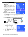
11b Configure
RX video recording server IP setting through PC
RX
192.168.0.2
RG59 cable
Ethernet Socket
Cameras
Power Adapter
Cross-over Ethernet Cable
Basic Installation for Local and Remote Monitoring
192.168.0.3
User Guide
Page 45
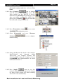
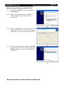
11.b.1. In Windows 2000/XP desktop, select Start >
Control Panel
11.b.2. Double click Network and Dial-up
Connections > right click Local Area
Connections and choose Properties.
11.b.3. Choose Internet Protocol (TCP/IP) and click
Properties
11.b.4. Enter an IP address, subnet mask and Default
gateway.
Note: IP address should be “192.168.0.xx”
except “192.168.0.2” which is
RX
default IP address.
11.b.5. Enter the Preferred and Alternate DNS server, if
necessary.
11.b.6. Click OK to activate the new IP.
You have to confirm that IP address has been
correctly set on your computer. On your
windows, click start > run, type “cmd” at
Open field and press OK button, then type
“ipconfig” on the DOS prompt, you will see an
IP set on your computer.
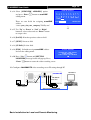
11.b.7. Connect the PC Ethernet socket to the video
recording server Ethernet socket at rear panel of
the video recording server with cross-over
Ethernet cable. Check if the {LINK LED} of
the video recording server is ON.
Basic Installation for Local and Remote Monitoring
10/100
LINK
BASE-T
COL
User Guide
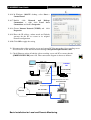
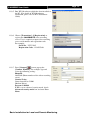
11.b.8. Run WX-30 software which has been installed
to the PC. (For details of WX-30 software
installation, please refer to WX-30 Software
Guide)
11.b.9. Choose [Transmitter] [Registration] to
register the
RX video recording
server. User needs to input video recording
server serial number and registration code.
For example :
Serial No. : VTC12345
Registration Code : 1234567890
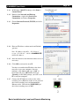
11.b.10. Press [Connect]
icon to pop up the
[Connect Window]. Type and select the
following setting :
Broadband Connection :
Phone/IP
: 192.168.0.2
Connect Using
: TCP/IP Broadband
Password
: 000000
OR
Narrowband Connection :
Phone/IP
: 192.168.0.2
Connect Using
: TCP/IP Narrowband
Password
: 000000
IP (192.168.0.2) and Password (000000) are
default setting of
RX
If RX is set to advanced security mode, check
Advanced security mode box and enter User
Name
Basic Installation for Local and Remote Monitoring
Page 46
User Guide
Page 47
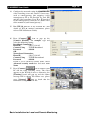
11.b.11. Press [Connect]
icon to connect your
PC and the video recording server. The video
appears on the WX-30 if success. Otherwise,
the [Warning] board will pop up and show you
failure message. For failure case, please press
[Connect]
icon to check that the
connection setting is valid or not.
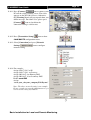
icon to show
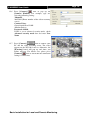
11.b.12. Press [Transmitter Setup]
RX configuration menu.
11.b.13. Select [Connection] and press [Network
Settings]
network setting.
icon to configure
11.b.14. For example :
Assign 210.17.139.5 to IP
Assign 210.17.139.1 to Gateway
Assign 202.14.67.4 to Primary DNS
Assign 202.14.67.14 to Secondary DNS
Enable sureLINK
Assign
“www.your_site.your_company.TeleEye.net”
Note: The above network setting is an example.
Please consult you network administrator to get
your network setting information
Basic Installation for Local and Remote Monitoring
User Guide
Page 48
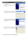
11.b.15. Press [Apply]
icon to save the
network setting and pop up the message board.
After several seconds, the video recording
server will restart automatically.
11.b.16. In Windows 2000/XP desktop, select Start >
Control Panel
11.b.17. Double click Network and Dial-up
Connections > right click Local Area
Connections and choose Properties.
11.b.18. Choose Internet Protocol (TCP/IP) and click
Properties
11.b.19. Enter the IP address, subnet mask and Default
gateway for the PC to restore to its original
network configuration.
11.b.20. Click OK to apply the setting
12. Disconnect the video recording server and current PC. Reconnect the video recording server
and current PC to the Internet network through straight-through Ethernet cable.
13. Check Ethernet socket of both the video recording server and PC to ensure that the
{GREEN LINK LED} turns ON. Then connection diagram is shown as follows:
RG59 cable
Primary DNS: 202.14.67.4
RX
CCTV
Secondary DNS: 202.14.67.14
Monitor
www.your_site.your_company.teleeye.net
RG59 cable
Cameras
Ethernet
Power Adapter
Socket
Straight-through Ethernet cable
Router/Gateway
211.134.139.9
210.17.139.1
Straight-through Ethernet cable
Internet
211.134.139.1
211.134.139.7
Router/Gateway
Basic Installation for Local and Remote Monitoring
User Guide
14. Configure the network setting for
RX
video recording server and your PC if necessary,
such as router/gateway port mapping (select
router/gateway IP as IP provided by your ISP and
the video recording server IP as IP provided by the
router/gateway), firewall, etc. (Please refers to the
manual of your router/gateway.)
15. Run WX-30 software at any network PC. (For
details of WX-30 software installation, please refer
to WX-30 Software Guide)
icon to pop up the [Connect
16. Press [Connect]
Window]. For example, type and select the
following setting :
Broadband Connection :
Phone/IP :
www.your_site.your_company.TeleEye.net
Connect Using
: TCP/IP Broadband
Password
: 000000
OR
Narrowband Connection :
Phone/IP :
www.your_site.your_company.TeleEye.net
Connect Using
: TCP/IP Narrowband
Password
: 000000
If RX is set to advanced security mode, check
Advanced security mode box and enter User
Name
17. Press [Connect]
icon to connect your
PC and the video recording server. The video
appears on the WX-30 if success. Otherwise, the
[Warning] board will pop up and the failure
message will be shown. For failure case, please
press [Connect]
icon to check that the
connection setting is valid or not.
Basic Installation for Local and Remote Monitoring
Page 49
User Guide
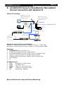
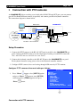
F.
Page 50
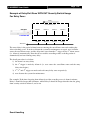
RX Setup for Modem Connection
Connection Topology
VIDEO OUT: Connect to
Modem port connect
monitor with RG59 cable
VIDEO IN: Connect to
to a DB-9 connector
and BNC connector
cameras with RG59 cable
and BNC connector
RG59 cable
RX
CCTV
Monitor
RG59 cable
Cameras
RS232 serial cable
Power Adapter
Telephone cable
Telephone
Modem
RS232 serial cable
Network
Telephone cable
Modem
Equipment
RX Video recording server
ISDN/PSTN Modem
RS232 Serial Cable
Telephone Cable
Cameras
Video Cables (RG-59) with BNC Header
CCTV Monitor
CD ROM with WX-30 Software (bundled) (for PC operation only)
PC
PC Requirements
CPU
: Pentium IV 2G Hz or above
RAM
: 256 MB or above
Display : 800x600, hi-color or better
OS
: MS Windows 2000, XP
Basic Installation for Local and Remote Monitoring
User Guide
Page 51
Setup Procedure
1.
Connect cameras to
RX {Video Input} with RG59 cable and BNC connector.
Note: The camera system is either NTSC or PAL and all cameras must have the SAME
system format.
RX {Video Output} with RG59 cable and BNC
2.
Connect CCTV monitor to
connector.
3.
Install and use the bundled key to lock the {Hard Disk Rack} with hard disk to the
RX.
Note: If there is no hard disk installed, Recording or Playback is not functional during live
video monitoring.
RX.
4.
Connect the power adapter (12V DC) to the
5.
Turn on the power of
RX, camera and monitor. Check the {Power LED}
,
which is lit up in blue color continuously at
RX front panel after power on.
After several seconds, live video appears on the CCTV monitor as follows:
Note: Please go through the following steps (6-10) if the video of CCTV monitor does not show
clearly.
Basic Installation for Local and Remote Monitoring
User Guide
6.
Press the “Menu”
MENU] on OSD.
7.
Use “Up”
Page 52
button to pop up the [MAIN
or “Down”
button to select
[SETUP] option and press “Enter”
enter the [SETUP] sub-menu.
8.
button to
Select [VIDEO] option and press “Enter”
button
SETUP MENU
VIDEO
RECORDING
SWITCHES
DATE / TIME
CONNECTION
EVENT HANDLER
TRANSMITTER
PASSWORD
USER ACCOUNT
RX-SE
SETTING IMPORT/EXPORT
RESTORE FACTORY SETTING
...
...
...
...
...
...
...
...
...
...
...
ENTER
VIDEO
9.
Select [VIDEO FORMAT] and press “Left”
or “Right”
button to set either [NTSC] or
[PAL] option. (All cameras should have the same
video format).
CAMERA SETTING
LOCAL MONITORING
SPOT VIDEO
VGA SETTING
OSD COLOR
VIDEO FORMAT
...
...
...
...
BLUE
PAL
10. You can always press “Live” button to exit any
menu operation and start live monitoring.
Setup
11a.
Setup
RX video recording server IP through CCTV monitor, please go to step
11a: Configure
CCTV Monitor
RX video recording server modem connection setting through
RX video recording server IP through PC, please go to step11b.
RX
RG59 cable
192.168.0.2
Ethernet
Power Adapter
Cameras
Socket
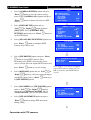
11.a.1. Press the “Menu” button such that the OSD
[MAIN MENU] pop up on the monitor.
11.a.2. Use “Up”
or “Down”
button to select
[SETUP] option and press “Enter”
button
and select [CONNECTION] option and press
“Enter”
button.
CCTV
RG59 cable
Monitor
SETUP MENU
VIDEO
RECORDING
SWITCHES
DATE / TIME
CONNECTION
EVENT HANDLER
TRANSMITTER
PASSWORD
USER ACCOUNT
RX-SE
SETTING IMPORT/EXPORT
RESTORE FACTORY SETTING
Basic Installation for Local and Remote Monitoring
...
...
...
...
...
...
...
...
...
...
...
ENTER
User Guide
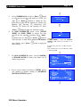
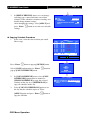
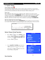
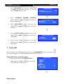
11.a.3. Use “Up”
Page 53
or “Down”
button to select
[MODEM] option and press “Enter”
button
CONNECTION
TCP / IP
MODEM
THROUGHPUT
11.a.4. Select [BAUD RATE] and then [RING
COUNT] option press “Enter”
11.a.5. Use “Up”
or “Down”
button
button to set
…
…
…
MODEM
INTERFACE
BAUD RATE
RING COUNT
TEST MODEM
USB
57600 BPS
1
ENTER
number. Press “Enter”
button to input baud
rate and ring count setting
MODEM
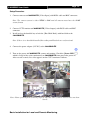
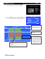
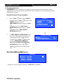
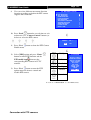
11.a.6. Select [TEST MODEM] and press “Enter”
button.
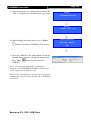
INTERFACE
BAUD RATE
RING COUNT
TEST MODEM
USB
57600 BPS
1
ENTER
MODEM TEST SUCCESS
11.a.7. Press [OK] and back to modem sub-menu.
Make sure the modem is connected and restart
the modem if the modem is not ready.
MODEM READY
OK
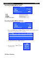
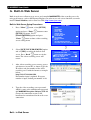
RX video recording server modem connection setting through PC
11.b: Configure
RG59 cable
RX
CCTV
Monitor
RG59 cable
Cameras
Power Adapter
RS232 serial cable
Telephone cable
Telephone
Modem
RS232 serial cable
Network
Telephone cable
Modem
Basic Installation for Local and Remote Monitoring
User Guide
Modem Setup for Windows 2000/XP of PC
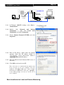
11.b.1. In Windows 2000/XP desktop, select Start >
Control Panel
11.b.2. Double click Add Hardware, press Next, to
search the modem connected to the PC
automatically
11.b.3. Windows 2000/XP can search the modem device
automatically. If there is any problem in modem
installation, please refer to the modem manual.
11.b.4. After searching the modem, Windows 2000/XP
can install the modem driver automatically. Press
[Finish] button to exit the menu. The modem is
ready to use.
Basic Installation for Local and Remote Monitoring
Page 54
User Guide
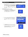
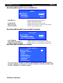
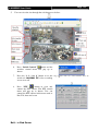
11.b.5. Run WX-30 software which has been installed to
the PC. (For details of WX-30 software
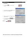
installation, please refer to WX-30 Software
Guide)
11.b.6. Choose [Transmitter] [Registration] to
register the
RX video recording
server. User is required to input video recording
server serial number and registration code.
For example :
Serial No. : VTC12345
Registration Code : 1234567890
icon to pop up the
11.b.7. Press [Connect]
[Connect Window]. For example, type and
select the following setting :
Phone/IP :
29955992 (Phone number of the video recording
server)
Connect Using :
General modem to COM1
(Modem Driver)
Password: 000000
If RX is set to advanced security mode, check
Advanced security mode box and enter User
Name
Basic Installation for Local and Remote Monitoring
Page 55
User Guide
Page 56
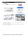
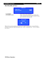
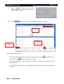
11.b.8. Press [Connect]
icon to connect your
PC and the video recording server. The video
appears on the WX-30 if success. Otherwise, the
[Warning] board will pop up and show you
failure message. For failure case, please press
icon to check that the connection
[Connect]
setting is valid or not.
11.b.9. Press [Transmitter setup]
icon to show
RX configuration menu.
11.b.10. Select [Connection] and press [Modem
Settings]
network setting.
icon to configure
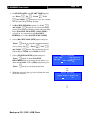
11.b.11. Assign modem baud rate in order to adjust
modem connection speed.
11.b.12. Assign ring count, so modem can connect to the
video recording server after that ring count.
11.b.13. Press [Apply]
icon to save the
network setting and the message board will pop
up. After several seconds, the video recording
server will restart automatically.
12. If user setup modem connection by using local CCTV monitor (Step 11a), please install the
modem for your PC and connect to the telephone network in order to connect to
RX video recording server
Basic Installation for Local and Remote Monitoring
User Guide
12.1
In Windows 2000/XP desktop, select Start >
Control Panel
12.2
Double click Add Hardware, press Next, to
search the modem connected to the PC
automatically
12.3
Windows 2000/XP can search the modem device
automatically. If there is any problem in modem
installation, please refer to the modem manual.
12.4
After searching the modem, Windows 2000/XP
can install the modem driver automatically. Press
[Finish] button to exit the menu. The modem is
ready to use.
12.5
Run WX-30 software which has been installed to
the PC. (For details of WX-30 software
installation, please refer to WX-30 Software
Guide)
Basic Installation for Local and Remote Monitoring
Page 57
User Guide
12.6
Press [Connect]
icon to pop up the
[Connect Window]. For example, type and
select the following setting :
Phone/IP :
29955992 (Phone number of the video recording
server)
Connect Using :
General modem to COM1
(Modem Driver)
Password: 000000
If RX is set to advanced security mode, check
Advanced security mode box and enter User
Name
12.7
Press [Connect]
icon to connect your
PC and the video recording server. The video
appears on the WX-30 if success. Otherwise, the
[Warning] board will pop up and show you
failure message. For failure case, please press
[Connect]
icon to check that the connection
setting is valid or not.
Basic Installation for Local and Remote Monitoring
Page 58
User Guide
Page 59
SECTION 4
Basic Operation for Local and
Remote Monitoring
A. Local CCTV Monitor : Live Monitoring, Recording
and Playback
1.
Live Monitoring
Press “Screen Control” buttons to view the live video in full, quad, 3 x 3
(RX368_V2/3616_V2 only), hex (RX3616_V2 only) and sequential display mode.
FULL
QUAD
SEQUENTIAL
3X3
HEX
for RX364, FULL, QUAD and SEQUENTIAL buttons are available
for RX368_V2, FULL, QUAD, 3X3 and SEQUENTIAL buttons are available
for RX3616_V2, FULL, QUAD, 3X3, HEX and SEQUENTIAL buttons are available
Press “Live Camera Control” buttons to fast switch to a specific camera for local
monitoring
for RX364, buttons 1-4 are available
for RX368_V2, buttons 1-8 are available
for RX3616_V2, buttons 1-16 are available
Basic Local Operation: Live Monitoring, Recording and Playback
User Guide
2.
1.
2.
Page 60
Recording
Press “Rec”
will pop up.
button and [RECORDING] menu
Select [REC CAMERA] option and press “Enter”
RECORDING
START RECORDING
REC CAMERA
START SCHEDULE REC
ENTER
---ENTER
button to enable recording cameras.
3.
Use “Left”
or “Right”
button to select
the recording camera and use “Up”
or “Down”
button to enable or disable the recording camera.
4.
Step 4: After setting the recording cameras, press
“Enter”
button to save the setting and back to
[RECORDING] menu.
5.
1-3(e.g.
Cam 1 & 3 are enabled, Cam 2 & 4 are
disabled)
RECORDING
START RECORDING
REC CAMERA
START SCHEDULE REC
Select [START RECORDING] option and press
“Enter”
button for recording. The {Rec LED}
will be turned ON (RED Color)
that recording is processing.
6.
RECORDING CAMERA
which indicates
Press “Rec” button again to stop recording
function and the {REC LED} will be turned OFF.
Basic Local Operation: Live Monitoring, Recording and Playback
ENTER
1-3–
ENTER
User Guide
Page 61
Playback
1.
Press “Search”
button to pop up
[RECORDING LOG] board on OSD.
2.
Press “Play/Enter”
menu.
3.
Select [MINUTE LOG] and press “Enter”
button.
button to show [PLAY]
[RECORDING LOG] board will show the log
in minute scale.
4.
Select a record and press “Enter”
playback.
button for
Then [PLAYBACK] menu will pop up again.
5.
Select [PLAY] option and press “Enter”
button again for playback.
6.
Using “Playback Control button” for
Play
Pause
Rewind
These icons will
Forward
shown on OSD
Fast
for playback
forward
status
Step
forward
Step
backward
7.
Press “screen control”
RECORDING LOG
TIME
CAMERA
11 : 00
1234
12 : 00
---4
13 : 00
---14 : 00
-2-15 : 00
---16 : 00
1---
EVENT
-------------------------
12 – 13 AUG2005
REMARK SENSOR
-------------- - - --------------------------------------
PLAY
TIME SEARCH
MONTH LOG
DAY LOG
HOUR LOG
10MIN LOG
MINUTE LOG
RECORDING LOG
TIME
CAMERA
11 : 54
1234
11 : 55
1234
11 : 56
1234
11 : 57
1234
11 : 58
1234
11 : 59
1234
EVENT
-------------------------
12 – 13 AUG2005
REMARK SENSOR
-------------- - - --------------------------------------
PLAY
TIME SEARCH
MONTH LOG
DAY LOG
HOUR LOG
10MIN LOG
MINUTE LOG
or “camera
control”
buttons to
change the view mode in local CCTV video
playback.
Basic Local Operation: Live Monitoring, Recording and Playback
User Guide
B.
Page 62
RX Reception Software WX-30 : Live
Monitoring, Recording and Playback
1. Live Monitoring
User can view a particular camera by simply clicking the camera button (e.g. 1, 2, 3) on the
camera control panel, to view all cameras, click [All]
button.
Screen views in Full screen
Screen views in Quarter screen
Screen views in Hex screen
Auto-arrange is to optimize the screen
views in order to display as many highresolution pictures as possible.
User can change
RX Reception Software
WX-30 live monitoring picture quality by following
steps.
1.
2.
3.
4.
5.
Click [Transmitter Settings]
button at the
software front panel.
Enter the administrator password to proceed.
A video recording server settings menu will pop
up.
Choose video properties under [video input] to
change the brightness, contrast and color
level.
Select in [Recording] to change the recording
quality and resolution.
Basic Remote Operation: Live Monitoring, Recording and Playback
User Guide
Page 63
2. Recording
1.
Press [Record]
setting.
2.
Input administrator password (000000 as default
password) and press [OK] button.
3.
Enable recording cameras ( Tick
blank for disable)
4.
Press [Start Recording]
to start recording
icon to setup recording
for enable,
button
Recording
function is running
Basic Remote Operation: Live Monitoring, Recording and Playback
User Guide
Page 64
3. Playback
1.
Press [Play]
2.
Select and input the record date and time for
button to show playback menu
searching and press [Reload]
3.
button.
Select a time slot record and press [Start
Playback]
button.
4.
Use “playback control button”
to
control playback video such as “play”, “pause”,
“forward”, “backward” and “stop” function.
5.
Press [All]
screen]
, [Full screen]
, [3X3 screen]
or [Auto-arrange]
view mode for playback.
, [Quarter
, [Hex screen]
icon to change the
Note: After pressing “pause” button for 1 minute, reception software WX-30 will continue to
playback the video automatically.
Note: If user record video by using quad recording mode, the playback video quality may not be
good as in full screen display mode.
Basic Remote Operation: Live Monitoring, Recording and Playback
User Guide
Page 65
SECTION 5
OSD Menu Operation
A. How to use OSD menu
1.
Press the “Menu”
2.
Use the “Up”
3.
A selected sub-menu option will be pointed by a hand cursor and highlighted
4.
Press “Enter”
5.
If menu option ends with [. . .] indicates sub-menu existing, you can always press the
“Enter”
button to open the main menu
/ “Down”
button to select a sub-menu
button to confirm the selection and open the sub-menu
button to open the sub-menu.
6.
If menu option does not end with [. . .] but provides selection, user can press the “Left”
/ “Right”
button to select the options.
7.
You can press the “Back”
8.
Press “Live”
button or “Back”
button until OSD disappears to exit menu and
save the setting. [SETTING SAVED] message will be shown.
OSD Menu Operation
button once back to previous menu.
User Guide
Page 66
B. Main Menu
The Main menu allows user to setup and control the video recording server, some
operations such as backup, switch, scandisk and format can be done in the main menu.
Main Menu
MAIN MENU
SETUP
FOOTAGE BACKUP
SWITCH CONTROL
SCAN / FORMAT DISK
TRANSMITTER INFO
LOCK KEYS
USER LOG-IN/OUT
SHUT DOWN
SETUP
FOOTAGE BACKUP
SWITCH CONTROL
SCAN / FORMAT DISK
TRANSMITTER INFO
LOCK KEYS
USER LOG-IN/OUT
SHUT DOWN
OSD Menu Operation
...
...
...
...
...
...
...
ENTER
: Change the
RX video recording server
setting
: Backup recorded video to CD, DVD or USB Flash
: Turn on /off switch 1-4
: Show the hard disk information, scandisk and format
RX video recording server
: Show the
information
: Lock the panel keys
: User log-in or log-out
: Shut down or restart
RX video recording
server
User Guide
Page 67
Main Menu Setup
SETUP MENU
VIDEO
RECORDING
SWITCHES
DATE / TIME
CONNECTION
EVENT HANDLER
TRANSMITTER
PASSWORD
USER ACCOUNT
RX-SE
SETTING IMPORT/EXPORT
...
...
...
...
...
...
...
...
...
...
...
VIDEO
: Change camera, local monitoring, PTZ setting, OSD
color and video format related settings
RECORDING
: Change recording related settings
SWITCHES
: Change switches related settings
DATE/TIME
: Change date and time settings
CONNECTION
: Change connection and network related settings
EVENT HANDLER
: Change event related settings
TRANSMITTER
: Change the video recording server name, registration
checking and perform firmware upgrade
PASSWORD
: Change the password
USER ACCOUNT
: Add / modify user account
RX-SE
: Change RX-SE setting
SETTING IMPORT /EXPORT
: Import and export setting
RESTORE FACTORY SETTING : Restore default factory setting
Main Menu
Setup Video
VIDEO
CAMERA SETTING
LOCAL MONITORING
SPOT VIDEO
VGA SETTING
OSD COLOR
VIDEO FORMAT
...
...
...
...
BLUE
PAL
CAMERA SETTING
: Change camera name and install camera
LOCAL MONITORING
: Change local CCTV monitor related setting
SPOT VIDEO*
: Change Spot video output setting
VGA SETTING*
: Change VGA output setting
OSD COLOR
: Change OSD color
VIDEO FORMAT
: Change the video format to PAL or NTSC format
*Note : only supported in RX368_V2 and RX3616_V2
OSD Menu Operation
User Guide
Main Menu
Page 68
Setup Video Camera Setting
CAMERA SETTING
CAMERA
CAMERA
CAMERA
CAMERA
1
2
3
4
CAMERA
CAMERA
CAMERA
CAMERA
13
14
15
16
...
...
...
...
.
.
.
...
...
...
...
Note: Number of items in this menu depends on video recording server model.
Main Menu
Setup Video Camera Setting
Camera 1 Setting
CAMERA 1 SETTING
INSTALLED
NAME
BRIGHTNESS
CONTRAST
COLOR
SUPPORT PTZ
INSTALLED
NAME
BRIGHTNESS
CONTRAST
COLOR
SUPPORT PTZ
GENERAL PTZ SETTING
YES
CAMERA 1
64
64
64
YES
: Install the camera
: Rename the camera
: Change camera brightness
: Change camera contrast
: Change camera color
: Enable the PTZ camera
: Change PTZ camera setting
*Note: BRIGHTNESS / CONTRAST / COLOR settings only available in RX368_V2 and RX3616_V2
OSD Menu Operation
User Guide
Main Menu
Page 69
Setup Video Camera Setting
Camera X Setting
General PTZ Setting
GENERAL PTZ SETTING
PAN SPEED
TILT SPEED
PTZ MOVEMENT SETTING
ADVANCE PTZ SETTING
PAN SPEED
TILT SPEED
PTZ MOVEMENT SETTING
ADVANCE PTZ SETTING
Main Menu
: Select the pan (horizontal direction) speed of the
PTZ camera
: Select the tilt (vertical direction) speed of the PTZ
camera
: Change the PTZ camera movement duration
: Change the PTZ camera driver and baud rate
Setup Video Camera Setting
General PTZ Setting
FAST
FAST
...
...
Camera X Setting
PTZ Movement Setting
PTZ MOVEMENT SETTING
PAN DURATION
TILT DURATION
ZOOM DURATION
FOCUS DURATION
IRIS DURATION
ADDITIONAL DURATION
WASHER DURATION
WIPER DURATION
PATROL SPEED
DWELL TIME
PAN DURATION
TILT DURATION
ZOOM DURATION
FOCUS DURATION
IRIS DURATION
ADDITIONAL DURATION
WASHER DURATION
WIPER DURATION
PATROL SPEED
DWELL TIME
OSD Menu Operation
5
5
3
3
3
3
3
3
3
2
: Select the PTZ camera pan duration
: Select the PTZ camera tilt duration
: Select the PTZ camera zoom duration
: Select the PTZ camera focus duration
: Select the PTZ camera iris duration
: Select the PTZ camera additional duration if any
: Select the PTZ camera washer duration
: Select the PTZ camera wiper duration
: Select the PTZ camera patrol speed
: Select the PTZ camera dwell time
User Guide
Main Menu
Page 70
Setup Video Camera Setting
General PTZ Setting
Camera X Setting
Advance PTZ Setting
ADVANCE PTZ SETTING
PTZ DRIVER
BIT RATE
PTZ DRIVER
BIT RATE
Main Menu
TELEEYE DM4 . . .
9600
: Select the PTZ camera driver
: Select the PTZ camera bit rate
Setup Video Local Monitoring
LOCAL MONITORING
CLOCK POSITION
CAMERA NAME POSITION
SEQUENTIAL SWITCH TIME
SEQUENTIAL MODE CAMERAS
DEFAULT DISPLAY MODE
HORIZONTAL POSITION
VERTICAL POSITION
HORIZONTAL SCALE
VERTICAL SCALE
CLOCK POSITION
CAMERA NAME POSITION
SEQUENTIAL SWITCH TIME
SEQUENTIAL MODE CAMERAS
DEFAULT DISPLAY MODE
HORIZONTAL POSITION
VERTICAL POSITION
HORIZONTAL SCALE
VERTICAL SCALE
BOTTOM
TOP
1SEC
1-3QUAD
5
0
10
2
: Change the clock position
: Change the camera name position
: Change the switch time between each live
camera display for sequential mode monitoring
: Select cameras for sequential mode monitoring
: Select default display mode in CCTV monitor
after
RX video recording server boot
up
: Change horizontal position of local video output
: Change vertical position of local video output
: Change horizontal scale of local video output
: Change vertical scale of local video output
For [HORIZONTAL POSITION], [VERTICAL POSITON], [HORIZONTAL SCALE]
and [VERTICAL SCALE] options, change these options if live video position or size display
does not fit in the local CCTV monitor.
OSD Menu Operation
User Guide
Main Menu
Page 71
Setup Video Spot Video
SPOT VIDEO
DEFAULT CAMERAS
SEQUENTIAL TIME
CLOCK POSITION
CAMERA NAME POSITION
Main Menu
12345678
3SEC
: Change the clock position
: Change the camera name position
Setup Video VGA Setting
VGA SETTING
VGA OUT
SPOT VGA OUT
RESOLUTION
FREQUENCY
VGA OUT
SPOT VGA OUT
RESOLUTION
FREQUENCY
OSD Menu Operation
DETECTED
NONE
1024X768
75HZ
: Change the clock position
: Change the camera name position
: Change VGA output resolution
: Change VGA output frequency
User Guide
Page 72
Main Menu Setup Recording
RECORDING
RECORDING MODE
CONTINUOUS
DISK MODE
CYCLIC
QUALITY
EXCELLENT
IMAGE SIZE
FULL
RECORDING AUDIO CHANNEL
AUDIO QUALITY
STANDARD
SCHEDULE RECORDING
...
RECORDING RETENTION
...
RECOVER RECORDING
ENTER
RECORDING MODE
DISK MODE
QUALITY
IMAGE SIZE
RECORDING AUDIO CHANNEL
AUDIO QUALITY
SCHEDULE RECORDING
RECORDING RETENTION
RECOVER RECORDING
: Change recording mode in 1, 2, 3, 4, 5 frame
per second (FPS) and continuous setting.
: Select the fix or cyclic disk mode
: Change recording quality with 5 levels
: Change recording video size in different
modes
: Select the recording audio channels
: Change audio quality with standard or high
quality
: Set up a recording schedule up to 1 week
: Set a retention period for recording
: Recover damaged recording log.
Note: Recording in cyclic disk mode can erase the oldest recording data in hard disk if the
hard disk is full, whereas recording will be stopped in fix disk mode
Note: 4 and 5 FPS are not supported in RX3616_V2 when recording image size is set to
FULL.
Recording Scheduler
Recording scheduler allows users to record video with user selected time. It supports 2
modes of schedule recording: normal recording and motion recording.
Normal type:
The video recording server records video with user selected frame rate. Continuous,
1FPS, 2FPS, 3FPS, 4FPS and 5FPS can be chosen in normal recording mode.
Motion type:
The video recording server records video of a camera if the selected motion block in
the camera detects motion during user selected time. Motion recording only provides
1FPS and continuous recording frame rate.
OSD Menu Operation
User Guide
Page 73
Main Menu Setup Recording Recording Audio Channel
RECORDING AUDIO
1-
Press “Up”
/ “Down”
/ “Left”
/ “Right”
to select the channel
Note: One audio channel for RX364. Two audio channels for RX3616_V2 and RX368_V2.
Recording audio channel 1 associates with camera 1. Recording channel 2 associates with
camera 2.
Adding Schedule In Calendar View
1.
Press “Menu”
button, select [SETUP] option and
press “Enter”
button to enter [SETUP] sub
menu. Select [RECORDING] option and press
“Enter”
button, then select [SCHEDULED
RECORDING] option and press “Enter”
to show recording scheduler menu.
2.
RECORDING MODE CONTINUOUS
DISK MODE
CYCLIC
EXCELLENT
QUALITY
IMAGE SIZE
FULL
RECORDING AUDIO CHANNEL
AUDIO QUALITY
STANDARD
SCHEDULED RECORDING
...
RECORDING RETENTION
...
RECOVER RECORDING
ENTER
Calendar View of recording schedule is shown.
Press “Enter”
view.
3.
button
RECORDING
button to add schedule or change
Select [ADD] option and press “Enter”
add a new recording schedule.
HOUR
00 : 00
02 : 00
04 : 00
06 : 00
08 : 00
10 : 00
12 : 00
14 : 00
16 : 00
18 : 00
20 : 00
22 : 00
SUNDAY
TIME SCALE
: REC
CAMERA
––––
––––
––––
––––
––––
––––
––––
––––
––––
––––
––––
––––
: MOTION REC
button to
OPTION
ADD
LIST VIEW
4.
Select [TYPE] option to choose schedule recording
type. [REC] for normal schedule recording.
[MOTION REC] for motion schedule recording.
OSD Menu Operation
ADD SCHEDULE
TYPE
REC
WEEKDAYS
S– – – – – –
START TI ME
00 : 00
END TIME
02 : 00
CAMERA
1234
FRAME RATE
CONTINUOUS
GENERAL MOTION SETTING
...
APPLY
ENTER
User Guide
5.
Page 74
Select [WEEKDAYS] and press “Enter”
button
to select the day of time slot added in a week. Use
SCHEDULE WEEKDAY
SMTWTFS
“Up”
or “Down”
button to enable the day.
From left to right, the day options are Sunday (S),
Monday (M), Tuesday (T), Wednesday (W),
Thursday (T), Friday (F) and Saturday (S). Press
6.
“Enter”
button to apply the weekdays setting.
In [ADD SCHEDULE] menu, select [START
TIME] and [END TIME] to choose the time
interval for the schedule recording. Press “Enter”
TI ME
02 : 00
button and use “Up”
or “Down”
button to Note that :
select the time. A time slot is minimum 10 minutes If [END TIME] is earlier than [START
long. Finally, press “Enter”
time settings.
7.
In [ADD SCHEDULE] menu, select [CAMERA]
or [FRAME RATE] to choose the frame rate or
camera respectively.
8.
If user selects motion recording in [TYPE] option,
user should set motion settings in [GENERAL
MOTION SETTING] option.
OSD Menu Operation
TIME], it will assume the end time is on
button to apply the next day.
E.g. Monday, start time : 18:00, end time :
09:00
The schedule period is from Monday 18:00
to Tuesday 09:00.
ADD SCHEDULE
TYPE
MOTION REC
WEEKDAYS
SMTWTFS
START TI ME
00 : 00
END TIME
02 : 00
CAMERA
1234
FRAME RATE
CONTINUOUS
GENERAL MOTION SETTING
...
APPLY
ENTER
ADD SCHEDULE
TYPE
MOTION REC
WEEKDAYS
SMTWTFS
00 : 00
START TI ME
END TIME
02 : 00
CAMERA
1234
FRAME RATE
CONTINUOUS
GENERAL MOTION SETTING
...
APPLY
ENTER
User Guide
9.
Page 75
Select the motion region and press “Enter”
10. Select [APPLY] and press “Enter”
button to
save the recording schedule setting of the time slot.
HOUR
00:00
02:00
04:00
06:00
08:00
10:00
12:00
14:00
16:00
18:00
20:00
22:00
←
SUNDAY
TIME SCALE
: REC
→
TYPE
MOTION REC
WEEKDAYS
SMTWTFS
START TI ME
00 : 00
END TIME
02 : 00
CAMERA
1234
FRAME RATE
CONTINUOUS
GENERAL MOTION SETTING
...
APPLY
ENTER
CAMERA
123546789ABCDEFG
123546789ABCDEFG
123546789ABCDEFG
123546789ABCDEFG
123546789ABCDEFG
123546789ABCDEFG
123546789ABCDEFG
123546789ABCDEFG
123546789ABCDEFG
123546789ABCDEFG
123546789ABCDEFG
123546789ABCDEFG
: MOTION REC
Red block means the timeslot is set to normal
recording.
Green block means the time slot is set to motion
recording.
Only one recording type can be set in one time slot
OSD Menu Operation
ADD SCHEDULE
One block of time slot on
calendar view represents a
10minute schedule, so one row
represents 2-hour schedule.
The row represents a period of
8:00-10:00
Red numbers means the
cameras is normal recording.
Green numbers means the
cameras is motion recording
White numbers means the
cameras are set to motion
and normal in the same row,
i.e. within 2 hours.
User Guide
11. Press “Live”
Page 76
button to exit OSD menu or press
“Back”
button to enter action menu again.
Press “Record” button to enter [RECORDING]
menu. Select [START SCHEDULE REC] and
press “Enter”
scheduler
START RECORDING
START RECORDING
REC. CAMERA
START SCHEDULE REC
ENTER
1234
ENTER
button to activate recording
Recording Scheduler in List View
1.
In calendar view, press “Enter”
button to pop
up [OPTION] menu. Select [LIST VIEW] and
press “Enter”
2.
ADD
LIST VIEW
button to enter list view.
List view schedule is shown. The schedule in list
view is same as the schedule in calendar view.
Press “Enter”
menu.
OPTION
button to pop up [OPTION]
START
00 : 00
09 : 00
10 : 00
12 : 00
14 : 00
16 : 00
18 : 00
19 : 00
22 : 00
SUNDAY
END
CAMERA
09 : 00
1234
10 : 00
12–4
12 : 00
1–3–
14 : 00
12––
16 : 00
1–3–
18 : 00
1–34
19 : 00
1234
22 : 00
1234
00 : 00
1–34
: REC
3.
In [OPTION] menu of list view, user can add,
remove, edit or copy schedule in list view. Select
[CALENDAR VIEW] and press “Enter”
button to return to calendar view.
OSD Menu Operation
FPS
C
2
1
3
4
5
C
1
C
: MOTION REC
OPTION
ADD
REMOVE
EDIT
COPY
CALENDAR VIEW
User Guide
Page 77
Removing Schedule Procedure
1. In list view, select the time slot that you would
like to remove.
START
00 : 00
09 : 00
10 : 00
12 : 00
14 : 00
16 : 00
18 : 00
19 : 00
22 : 00
SUNDAY
END
CAMERA
09 : 00
1234
10 : 00
12–4
12 : 00
1–3–
14 : 00
12––
1–3–
16 : 00
18 : 00
1–34
19 : 00
1234
22 : 00
1234
00 : 00
1–34
: MOTION REC
: REC
2.
Press “Enter”
button to pop up [OPTION]
OPTION
ADD
REMOVE
EDIT
COPY
CALENDAR VIEW
menu. Select [REMOVE] and press “Enter”
button to pop up [REMOVE OPTION] menu.
3.
Select [REMOVE SELECTED] to remove the
selected schedule. User may choose [REMOVE
DAY] to remove all schedules for the whole day.
Or, choose [REMOVE WEEK] to remove all
schedules in a week. Select [CANCEL] to exit
the menu without removing schedule.
Editing Schedule Procedure
1. In list view, select a time slot that you would like to
edit.
REMOVE OPTION
REMOVE SELECTED
REMOVE DAY
REMOVE WEEK
CANCEL
START
00 : 00
09 : 00
10 : 00
12 : 00
14 : 00
16 : 00
18 : 00
19 : 00
22 : 00
SUNDAY
END
CAMERA
1234
09 : 00
10 : 00
12–4
12 : 00
1–3–
14 : 00
12––
16 : 00
1–3–
18 : 00
1–34
19 : 00
1234
22 : 00
1234
00 : 00
1–34
: REC
2.
Press “Enter”
button to pop up [OPTION]
menu. Select [EDIT] and press “Enter”
to pop up [EDIT SCHEDULE] menu.
OSD Menu Operation
button
FPS
C
2
1
3
4
5
C
1
C
FPS
C
2
1
3
4
5
C
1
C
: MOTION REC
OPTION
ADD
REMOVE
EDIT
COPY
CALENDAR VIEW
User Guide
3.
Page 78
In [EDIT SCHEDULE] menu, user can change
recording type, camera and frame rate of that
schedule. If the schedule is motion recording, user
should change motion settings.
After changing the settings, select [APPLY] and
press “Enter”
settings.
EDIT SCHEDULE
TYPE
MOTION REC
CAMERA
1234
FRAME RATE
CONTINUOUS
GENERAL MOTION SETTING
...
APPLY
ENTER
button to save the new schedule
Copying Schedule Procedure
1. In list view, select the time slot that you would
like to copy.
START
00 : 00
09 : 00
10 : 00
12 : 00
14 : 00
16 : 00
18 : 00
19 : 00
22 : 00
SUNDAY
END
CAMERA
09 : 00
1234
10 : 00
12–4
12 : 00
1–3–
14 : 00
12––
16 : 00
1–3–
18 : 00
1–34
19 : 00
1234
22 : 00
1234
00 : 00
1–34
: MOTION REC
: REC
Press “Enter”
button to pop up [OPTION] menu.
Select [COPY] option and press “Enter”
pop up [COPY SCHEDULE] menu.
2.
3.
button to
In [COPY SCHEDULE] menu, select [COPY
SCHEDULES] option and user should set
[SINGLE SCHEDULE] to copy the selected
schedule of the day or set [ENTIRE DAY] to
copy all schedules of the day.
Select [COPY TO WEEKDAYS] option to set
the day that the schedule copies to. Select
[APPLY] option and press “Enter”
copy the schedule.
OSD Menu Operation
button to
FPS
C
2
1
3
4
5
C
1
C
OPTION
ADD
REMOVE
EDIT
COPY
CALENDAR VIEW
COPY SCHEDULE
COPY SCHEDULES SINGLE SCHEDULE
COPY TO WEEKDAYS
X– – – – – –
APPLY
ENTER
User Guide
Page 79
Recording Retention
RX video recording server supports password protection for all menus, System
administrator can setup a password to protect the video recording server from being operated by
unauthorized operators
Record Retention Setup Procedure
1.
Press “Menu”
button, select [SETUP]
option and press “Enter”
button to enter
[SETUP] sub menu. Select
[RECORDING] option and press “Enter”
button, then select [RECORD
RETENTION] option and press “Enter”
RECORDING
RECORDING MODE CONTINUOUS
DISK MODE
CYCLIC
QUALITY
EXCELLENT
IMAGE SIZE
FULL
SCHEDULED RECORDING
...
RECORDING RETENTION
...
button to show [RECORDING
RETENTION] menu.
2.
In [RECORDING RETENTION] menu,
user and enable/disable this function, set
retention period and schedule time for
retention. Press “Enter”
button after
selecting [RETENTION PERIOD
(DAYS)] / [SCHEDULE TIME FOR
RETENTION] and use “Up”
“Down”
time.
RECORDING RETENTION
ENABLE
RETENTION PERIOD (DAYS)
SCHEDULE TIME FOR RETENTION
or
button to select the period /
Main Menu Setup Switches
SWITCHES
SWITCH
SWITCH
SWITCH
SWITCH
1
2
3
4
SETTING
SETTING
SETTING
SETTING
Change the switch setting by choosing “SWITCH 1, 2, 3 and 4”
OSD Menu Operation
...
...
...
...
YES
999
08:00
User Guide
Main Menu
Page 80
Setup
Switches
Switch 1 Setting
SWITCH 1 SETTING
NAME
TYPE
NAME
TYPE
Main Menu
SWITCH 1
LATCHING
: Edit the name of the switch
: Change the type of the switch, either latching or
push-button type
Setup
Date Time Setup
DATE / TIME
TIME SYNC ENABLED
TIME ZONE
DATE
TIME
PRI TIME SERVER
SEC TIME SERVER
DNS SETTING
UPDATE DATE / TIME
STATUS
TIME SYNC ENABLED
TIME ZONE
DATE
TIME
PRI TIME SERVER
SEC TIME SERVER
DNS SETTING
UPDATE DATE/TIME
STATUS
YES
...
11 MAR 2006
11 : 03
TIME . WIND . .
TIME . N IST . .
...
ENTER
SUCCESS
: Enable/Disable time synchronization
: Change the time zone
: Set the current date
: Set the current time
: Set a primary time server
: Set a secondary time server
: Change the network setting
: Update date/time from server
: Show the status of time sync
Modify system time
1.
System date and time can only be modified when TIME SYNC is disabled.
2.
Press “Enter”
button to select [DATE TIME] or [TIME] option
DATE
24
DATE
AUG
TIME
2005
TIME
15 : 18
3.
Press “Left”
/ “Right”
button to select date, month, year for [DATE TIME] or
select hour, minutes for [TIME] option
4.
Press “Up”
5.
Press “Enter”
/ “Down”
button to change the value
button to save setting and exit this page of menu
OSD Menu Operation
User Guide
Main Menu
1.
2.
Setup
Page 81
Date/Time
Time Zone
Select a corresponding time zone will
enable Daylight saving function.
Press “Left”
/ “Right”
button to select between time zones
(GMT).
←GMT +08:00→
→
3.
Press “Up”
/ “Down”
button to
select between different cities
4.
Press “Enter”
button to save setting
and back to previous menu.
Main Menu
Setup
GMT +08:00
ANTARCTICA/CASEY
ASIA/BRUNEI
ASIA/CHONGQING
ASIA/CHUNGKING
ASIA/HARBIN
ASIA/HONG_KONG
ASIA/IRKUTSK
ASIA/KASHGAR
ASIA/KUALA_LUMPUR
ASIA/KUCHING
ASIA/MACAO
ASIA/MACAU
.
.
PAGE 1/3
Connection
CONNECTION
TCP / IP
MODEM
THROUGHPUT
TCP / IP
MODEM
THROUGHPUT
Main Menu
Setup
…
…
…
: Configure TCP/IP network related setting
: Configure modem related setting
: Configure throughput control setting
Connection
TCP / IP
TCP / IP
IP
PORT
SUBNET MASK
ENABLE GATEWAY
GATEWAY
ENABLE DNS
PRIMARY DNS
SECONDARY DNS
SURELINK
IP
PORT
SUBNET MASK
: Change
: Change
: Change
ENABLE GATEWAY
: Enable
GATEWAY
ENABLE DNS
OSD Menu Operation
192.168.0.2
1024
255.255.255.0
NO
0.0.0.0
NO
0.0.0.0
0.0.0.0
…
RX video recording server IP
RX video recording server port
RX video recording server
subnet mask
RX video recording server
gateway setting
: Change
RX video recording server
gateway
RX video recording server DNS
: Enable
setting
User Guide
PRIMARY DNS
SECONDARY DNS
SURELINK
Main Menu
Setup
Page 82
RX video recording server
primary DNS
: Change
RX video recording server
secondary DNS
RX video recording server
: Change
sureLINK setting
: Change
Connection
TCP / IP
sureLINK
SURELINK
ENABLED
SURELINK ADDRESS
REFRESH RATE
ADVANCED SETTING
TEST
STATUS
ENABLED
SURELINK ADDRESS
REFRESH RATE
ADVANCED SETTING
TEST
STATUS
YES
WWW . . . . .
15 MINS
...
ENTER
WORK IN PROGRESS
: Enable sureLINK option
: Change the
RX video recording server
sureLINK address
: Select the sureLINK refresh rate
: Set the primary and secondary sureLINK domain
: Test connection to sureLINK server
: The status of the sureLINK
Note: There are three status; success, work in progress and fail. Success means it connects
to the sureLINK server successfully.
Main Menu
Setup
Connection
TCP / IP
sureLINK
Advanced setting
ADVANCED SURELINK SETTING
PRI. SURELINK DOMAIN
SEC. SURELINK DOMAIN
1.
Select [PRI. SURELINK DOMAIN] and press “Enter”
sureLINK suffix.
2.
After inputting the primary sureLINK domain, select [SEC. SURELINK DOMAIN]
and press “Enter”
OSD Menu Operation
button to set the primary
button to set the secondary sureLINK suffix.
User Guide
Main Menu
Setup
Page 83
Connection
Modem
MODEM
INTERFACE
BAUD RATE
RING COUNT
TEST MODEM
INTERFACE
: Change the interface of the modem
(USB/COM POT/DISABLE)
: Change the baud rate of the modem
: Change the ring count to connect to the modem
: Test the status of the modem
BAUD RATE
RING COUNT
TEST MODEM
Main Menu
Setup
COM PORT
57600 BPS
1
ENTER
Connection
Throughput
THROUGHPUT
LAN STREAM
BROADBAND STREAM
NARROWBAND STREAM
BPS : BIT PER SECOND
LAN STREAM
BROADBAND STREAM
NARROWBAND STREAM
Main Menu
Setup
100M BPS
40M BPS
128K BPS
: Change the data rate of LAN connection
: Change the data rate of broadband connection
: Change the date rate of narrowband connection
Event Handler
EVENT HANDLER
ARM / DISARM
SECURITY SWITCH
ALARM
MOTION
VIDEO LOSS
SYSTEM TAMPER
POWER FAILURE
DISK USAGE
OVERHEAT
HDD AVAILABLE
...
...
...
...
...
...
...
...
...
...
The event handler menu contain 9 functions (ARM/DISARM, SECURITY SWITCH,
ALARM, MOTION, VIDEO LOSS, SYSTEM TAMPER, POWER FAILURE, DISK
USAGE, OVERHEAT and HDD Available)
OSD Menu Operation
User Guide
Main Menu
Setup
Page 84
Transmitter
TRANSMITTER
TRANSMITTER NAME
REGISTRATION CHECKING
BUILT-IN WEB SERVER
UPGRADE
TRANSMITTER NAME
REGISTRATION CHECKING
BUILT-IN WEB SERVER
UPGRADE
Main Menu
Setup
RX364
YES
NO
...
: Rename the video recording server
: Check if the serial number of the video recording
server match the serial number registered in the
reception software WX-30 or not
: Change the status of built-in server
: Upgrade new version firmware
Transmitter Upgrade
FIRMWARE UPGRADE
UPGRADE FROM USB
UPGRADE FROM CD
ENTER
ENTER
The new version firmware can be upgraded via USB or CD
Note: User needs to install a formatted hard disk first before the firmware upgrade through
CD
Main Menu
Setup
Password
PASSWORD MENU
ENABLE EVENT MENU PASSWORD
ENABLE RECORDING MENU PASSWORD
ENABLE SEARCH MENU PASSWORD
ENABLE MAIN MENU PASSWORD
ENABLE KEYS LOCKED PASSWORD
CHANGE PASSWORD
ENABLE EVENT MENU PASSWORD
ENABLE RECORDING MENU PASSWORD
ENABLE SEARCH MENU PASSWORD
ENABLE MAIN MENU PASSWORD
ENABLE KEYS LOCKED PASSWORD
CHANGE PASSWORD
*Note: default password = 111111
OSD Menu Operation
NO
NO
NO
NO
NO
...
: Change the status of event menu password
: Change the status of recording menu
password
: Change the status of search menu password
: Change the status of main menu password
: Change the status of keys locked password
: Setup a new password
User Guide
Main Menu
Page 85
Footage Backup
FOOTAGE BACKUP
BACKUP TO CD
BACKUP TO DVD
BACKUP TO USB FLASH
BACKUP TO CD
BACKUP TO DVD
BACKUP TO USB FLASH
...
...
...
: Backup footage to CD-R
: Backup footage to DVD-R
: Backup footage to USB Flash
FOOTAGE BACKUP
BACKUP TO :
CD
MODE
ALL CAMERAS
CAMERA
1234
START DATE
30 JAN 2007
START TIME
17:11
BACKUP PERIOD
5 MINS
BACKUP MAX SIZE (MB)
650
START BACKUP
ENTER
MODE
CAMERA
START DATE
START TIME
BACKUP PERIOD
MAX BACKUP SIZE
START BACKUP
Main Menu
Switch Control
: Set the backup type (ALL CAMERAS / SELECT
CAM / QUICK)
: Choose backup cameras
: Set the start date of the footage
: Set the start time of the footage
: Set the backup period
: Set the backup size (10MB ~ 650 MB for CD, 10MB
~ 4700 MB for DVD and USB Flash)
RX video
: Start Backup operation, and
recording server will search the footages from start
date and time and calculate the end time of footage
according to the footages size and backup size.
SWITCHES
USE CAM KEYS TO
CONTROL SWITCHES
NO
1
2
3
4
NAME
SWITCH
SWITCH
SWITCH
SWITCH
1
2
3
4
ON
BACK
SWITCHES
USE CAM KEYS TO
CONTROL SWITCHES
OFF
OFF
OFF
OFF
OFF
NO NAME
OFF
1 SWITCH
2 SWITCH
3 SWITCH
4 SWITCH
ON
1
2
3
4
ON
ON
ON
ON
The switches can be controlled by pressing the cam keys (1, 2, 3 and 4) respectively. And the
screen will show the current status (ON/OFF) of switches
SWITCH 1
SWITCH 2
SWITCH 3
SWITCH 4
OSD Menu Operation
: Control by cam key 1
: Control by cam key 2
: Control by cam key 3
: Control by cam key 4
User Guide
Main Menu
Page 86
Scan / Format Disk
SCAN / FORMAT DISK
DEVICE
LOCAL
START TIME
22:35 20/06/06
END TIME
10:07 15/11/06
MASTER MODEL NO
XXXX
MASTER SERIAL NO
XXXX
MASTER CAPACITY
400GB
SLAVE MODEL NO
N/A
SLAVE SERIAL NO
SLAVE CAPACITY
DISK USAGE
52%
SCAN DISK
ENTER
FORMAT DISK
ENTER
DEVICE
START TIME
END TIME
MODEL NO
SERIAL NO
CAPACITY
DISK USAGE
SCANDISK
FORMAT
: Show the device type
: Show the start time of recording
: Show the end time of recording
: Show the device model no.
: Show the device serial no.
: Show the capacity of the device
: Show the disk usage in percentage
: Start HDD scanning operation
: Start HDD formatting operation
Note :
Start time is the first recording time and end time is the latest recording time in RX. Select
[DEVICE] and use “Left”
or “Right”
button to choose RX-SE. It will show the
first and the lastest recording time of RX-SE in START TIME and END TIME. The
information under the scan/format disk sub-menu will be changed after formatted disk.
Main Menu
Transmitter Information
TRANSMITTER INFORMATION
TRANSMITTER NAME
TRANSMITTER IP
MODEL NO .
SERIAL NO .
VERSION
TRANSMITTER NAME
TRANSMITTER IP
MODEL NO.
SERIAL NO.
VERSION
OSD Menu Operation
RX364
192.168.0.2
RX364
VTCXXXXX
01.00
: Show the video recording server name
: Show the video recording server IP address
: Show the video recording server model no.
: Show the video recording server serial no.
: Show the video recording server firmware version
User Guide
Main Menu
Page 87
Lock Keys
LOCK KEYS
LOCK KEYS
AUTO KEY LOCK
LOCK KEYS
AUTO KEY LOCK
ENTER
15SEC
: Lock all keys on the front panel
: Select auto key lock duration, keys on front panel
will be automatically locked up if no button is being
pressed after the selected period.
KEY LOCKED
UNLOCK ?
YES
NO
When the keys are being locked, pressing any key on the front panel the system will show a
message to confirm the unlock operation. Select “YES” to unlock the keys , “NO” to keep the
keys locked.
OSD Menu Operation
User Guide
Page 88
C. Recording Log Menu
RECORDING LOG
TIME
CAMERA
11 : 00
1234
12 : 00
---4
13 : 00
---14 : 00
-2-15 : 00
---16 : 00
1--17 : 00
1---
TIME
CAMERA
EVENT
REMARK
SENSOR
MOTION
AUDIO
VIDEOLOSS
1.
Press “Enter”
scale
2.
Press the “Back”
EVENT
-----------------------------
12 – 13 AUG2005
REMARK SENSOR MOTION AUDIO VIDEOLOSS
---------------------------------------------------------- - - -------------------------------------------------------
: Show date of log
: Show time of log
: Show event triggered
: Items are not available now
: Show alarm sensor triggered
: Show motion trigger in which camera
: Show audio channel
: Show camera video loss
button to choose play recording log, time search function and log time
button to exit the recording log menu
PLAY
TIME SEARCH
MONTH LOG
DAY LOG
HOUR LOG
10MIN LOG
MINUTE LOG
PLAY
TIME SEARCH
MONTH LOG
DAY LOG
HOUR LOG
10MIN LOG
MINUTE LOG
OSD Menu Operation
: Play the current selected record
: Search specify time recording log and play it
: Change the recording log scale to month
: Change the recording log scale to day
: Change the recording log scale to hour
: Change the recording log scale to 10 minutes
: Change the recording log scale to 1 minute
User Guide
Page 89
Recording Log Menu Time Search
TIME SEARCH
DATE
TIME
`
CAMERA
SEARCH
SEARCH MULTIPLE
DATE
TIME
CAMERA
SEARCH
SEARCH MULTIPLE
13 SEP 2005
10 : 30
1234
ENTER
ENTER
: Select the date of record
: Select the time of record
: Select the camera of record
: Search the record
: Search the multiple records
Recording Log Menu Search Multiple
TIME SEARCH
DATE
TIME
CAMERA
SEARCH
SEARCH MULTIPLE
13 SEP 2005
10 : 30
1234
ENTER
ENTER
1. Select search multiple and press “Enter”
button. Multiple results will show if there
is more than one record included in the search time.
SEARCH RESULT
NO.
CAMERA
1
1234
2
---4
3
12 - 4
-2--
EVENT
-----------------
10:30 13 SEP2005
REMARK SENSOR MOTION AUDIO VIDEOLOSS
---------------------------------------------------------- - - ----------
2. Select the number and press “Enter”
3. Select play and Press “Enter”
to view the result.
OSD Menu Operation
button
button.
PLAY
TIME SEARCH
MONTH LOG
DAY LOG
HOUR LOG
10MIN LOG
MINIUTE LOG
User Guide
Page 90
D. PTZ Menu
1.
For any camera supports PTZ, [PTZ OPTION] menu always pops up when user press the
“Live”
2.
button. Select [DISABLE PTZ] to disable PTZ function.
Use the “Up”
/ “Down”
button to select each option
PTZ Control Interface
PTZ symbol
will flash near the camera name on the OSD for current controlling PTZ
camera. User can use front panel to perform pan / tilt / zoom action of the selected PTZ
supported camera anytime when live monitoring on OSD.
PTZ Control Method :
1.
Press “Live”
button to pop up PTZ control options.
Select any options and press “Enter”
pop up.
button to
2.
For example, if [IRIS CTRL] is selected. Iris control
menu will pop up. Use “Left”
or “Right”
button to control - or + the value respectively.
3.
To Recall Preset, Program Preset and Recall Patrol
options, Press “Live Camera Control Buttons” to
select preset numbers.
Use “Up”
, “Down”
buttons to select other PTZ
camera control as example on the left.
OSD Menu Operation
PTZ OPTION
RECALL PRESET
PROGRAM PRESET
RECALL PATROL
STOP PATROL
AUX PAN
IRIS CTRL
FOCUS CTRL
AUX CTRL
IRIS -<
>+
RECALL PRESET NO.
FOCUS -<
>+
User Guide
Page 91
E. Recording Menu
RECORDING
START RECORDING
REC CAMERA
START SCHEDULE REC
1. Press the “Rec”
2. Using the “Up”
ENTER
---ENTER
button to pop up the main menu
/ “Down”
START RECORDING
RECORDING CAMERA
START SCHEDULE REC
button to select recording and set recording camera
: Start recording operation
: Select the camera for recording
: Start scheduled recording
Recording Menu Recording Camera
RECORDING CAMERA
1-3-
1. Using the “Left”
2. Press the “Up”
/ “Right”
/ “Down”
button to select camera
button to enable or disable camera for recording
3. Press “Enter”
button to confirm the selection. Press the “Back”
without saving any recording camera setting
F. Event Menu
EVENT MENU
EVENT STATUS
EVENT LOG
CONNECTION LOG
SETTING LOG
OPERATION LOG
OSD Menu Operation
...
...
...
...
...
button to exit
User Guide
Page 92
1. Press the “Event”
button to pop up the event menu
2. Using the “Up”
/ “Down”
button to select a sub-menu
3. A selected sub-menu option will be pointed by a hand cursor and highlighted
4. Press “Enter”
button to confirm the selection and pop up the sub-menu
EVENT STATUS
EVENT LOG
CONNECTION LOG
SETTING LOG
OPERATION LOG
: Show event status
: Show the event log
: Show the remote connection log
: Show the setting log
: Show the operation log
1. If menu option end with [. . .] indicates sub-menu existing, you can always press “Enter”
button to pop up the sub-menu.
2. Press the “Back”
Event Menu
button back to previous menu and “Live”
button to exit menu.
Event Status
EVENT STATUS
ALARM
MOTION
VIDEO LOSS
DISK FULL
OVERHEAT
TAMPER
POWER FAILURE
HDD AVAILABLE
CLEAR EVENT
ALARM
MOTION
VIDEO LOSS
DISK FULL
OVERHEAT
SYSTEM FAILURE
TAMPER
POWER FAILURE
HDD AVAILABLE
CLEAR EVENT
OSD Menu Operation
1234
12
- - 34
NORMAL
NORMAL
SYS/ARMSECSW
FAIL
...
ENTER
: Show the alarm status
: Show the motion status
: Show the video loss status
: Show the hard disk status
: Show the overheat status
: Show the system status
: Show the arm, security switch and system tamper
status
: Show the status of power failure input
: Show the HDD ststus
: Clear event
User Guide
Event Menu
Page 93
Alarm Log
ALARM LOG
DATE
TIME
CHANNEL
STATUS
03AUG05
03AUG05
02AUG05
02AUG05
01AUG05
01AUG05
01AUG05
01AUG05
---4------4-----------2------------1------1--------------
RESET
TGR
ARM
TAMPER
SS ON
RESET
TGR
ENTRY
DATE
TIME
CHANNEL
STATUS
12 : 45 : 18
12 : 29 : 46
09 : 50 : 33
09 : 35 : 02
11 : 05 : 03
10 : 25 : 36
10 : 10 : 10
09 : 29 : 17
------
R- D - B- --------
--------E------------ S- E - P
------
: Show the date log
: Show the time log
: Show the event number (alarm / motion & videoloss only)
: Show the status. Full description of status is shown as follow:
Display
TGR
TAMPER
RESET
CLEAR
ARM
DISARM
SS ON
SS OFF
ENTRY
EXIT
ACTION
ACTION
Description
Event trigger
Alarm tampered
Event reset
User clear event status
System is armed
System is disarmed
Security switch turned on
Security switch turned off
Event trigger during entry delay time
Event trigger during exit delay time
: Show the event associated action
Display
R
S
D
E
M
B
P
L
OSD Menu Operation
Description
Recording
Switch
Dial back
E-mail notification
SMS
Buzzer
Recall Preset PTZ position
Associate camera to local monitor
User Guide
Event Menu
Page 94
Connection Log
CONNECTION LOG
DATE
TIME
USER
REMARK
IP/PHONE NO
DEVICE
22AUG05
22AUG05
21AUG05
21AUG05
20AUG05
20AUG05
20AUG05
20AUG05
ADMIN
ADMIN
ADMIN
ADMIN
ADMIN
ADMIN
ADMIN
ADMIN
- - - DIAL IN
- - - DIAL BACK
- - - DIAL BACK
- - - DIAL BACK
192.168.0.2
192.168.0.2
192.168.0.2
192.168.0.2
192.168.0.2
192.168.0.2
192.168.0.2
192.168.0.2
TCP / IP
TCP / IP
TCP / IP
TCP / IP
TCP / IP
TCP / IP
TCP / IP
TCP / IP
12 : 45 : 18
12 : 29 : 46
09 : 50 : 33
09 : 35 : 02
11 : 05 : 03
10 : 25 : 36
10 : 10 : 10
09 : 29 : 17
DATE
TIME
USER
DISCONNECTED
CONNECTED
DISCONNECTED
CONNECTED
DISCONNECTED
CONNECTED
DISCONNECTED
CONNECTED
: Show the date log
: Show the time log
: Show the user type connected to the video recording
server through remote software
: Show the connection triggered by user or dialback
action
DIAL IN Remote connect to video recording server
DIAL BACK Transmitter connect to remote
: Show the IP or phone number of the remote host
: Show connection method by the remote software
: Show the connection status
REMARK
IP/PHONE NO.
DEVICE
STATUS
Event Menu
STATUS
Setting Log
SETTING LOG
DATE
TIME
OPERATION
03DEC05
03DEC05
02DEC05
02DEC05
01DEC05
01DEC05
01DEC05
01DEC05
ALARM SEN TYPE
MOTION
RECORD MODE
VIDEOLOSS
VIDEO FORMAT
ALARM TMR TYPE
ALARM
CAMERA
12 : 45 : 18
12 : 29 : 46
09 : 50 : 33
09 : 35 : 02
11 : 05 : 03
10 : 25 : 36
10 : 10 : 10
09 : 29 : 17
DATE
TIME
OPERATION
CHANNEL
REMARK
DEVICE
IP / PHONE NO
OSD Menu Operation
CHANNEL REMARK
---4
---4
----2----1--1----3-
NC
ENABLED
CONTINUOUS
ENABLED
NTSC
DEOL
ENABLED
INSTALLED
DEVICE
IP / PHONE NO
TCP / IP
LOCAL
LOCAL
LOCAL
TCP / IP
TCP / IP
LOCAL
LOCAL
192.168. 0. 2
0. 0. 0. 0
0. 0. 0. 0
0. 0. 0. 0
192.168. 0. 2
192.168. 0. 2
0. 0. 0. 0
0. 0. 0. 0
: Show the date log
: Show the time log
: Show the setting that was done by user (Please refer
to the Appendix)
: Show the channel for the setting, such as alarm
sensor number, camera number
: Show the set value of the setting
: Show the setting that was done by which type of user
: Show the IP or phone number for the remote user
User Guide
Event Menu
Page 95
Operation Log
OPERATION LOG
DATE
TIME
OPERATION
DEVICE
IP / PHONE NO
03DEC05
03DEC05
02DEC05
02DEC05
01DEC05
01DEC05
01DEC05
01DEC05
STOP PLAYBACK
START PLAYBACK
STOP RECORDING
START RECORDING
STOP PLAYBACK
START PLAYBACK
STOP RECORDING
START RECORDING
TCP / IP
LOCAL
LOCAL
LOCAL
LOCAL
TCP / IP
LOCAL
TCP / IP
192.168. 0. 2
0. 0. 0. 0
0. 0. 0. 0
0. 0. 0. 0
0. 0. 0. 0
192.168. 0. 2
0. 0. 0. 0
192.168. 0. 2
12 : 45 : 18
12 : 29 : 46
09 : 50 : 33
09 : 35 : 02
11 : 05 : 03
10 : 25 : 36
10 : 10 : 10
09 : 29 : 17
DATE
TIME
OPERATION
DEVICE
IP / PHONE NO
: Show the date log
: Show the time log
: Show the operation done by user (Please refer to the
Appendix)
: Show the setting done by which type of user
: Show the IP or phone number for the remote user
Search Log
For each log, you can press “Enter”
button to enter the log option, and press “Enter”
button in [TIME SEARCH] option to enter search log menu.
SEARCH LOG
LOG OPTION
DATE
TIME
SEARCH
TIME SEARCH
EVENT PLAYBACK
20 SEP 2005
10 : 19
ENTER
The connection log contains the following options
DATE
TIME
SEARCH
OSD Menu Operation
: Set the search date
: Set the search time
: Search the nearest record according to the date and
time
User Guide
Page 96
Playing corresponding footage from event Log
Event log playback supports user to playback the video directly from selected event log.
Event Log Playback Procedure :
EVENT LOG
1.
Press “Event”
button to pop up the
event menu. Select [EVENT LOG]
option and press “Enter”
view all kinds of event logs.
2.
3.
4.
button to
For example, selecting [ALARM LOG]
and press “Enter”
alarm log menu.
button to enter
In the alarm log menu, press “Enter”
button to pop up [LOG OPTION] menu.
If there exists a corresponding recording
event, [EVENT PLAYBACK] option
will be included in the [LOG OPTION]
menu for playback the video.
Select [EVENT PLAYBACK] and press
“Enter”
button to watch the playback
for this event.
OSD Menu Operation
ALARM LOG
MOTION LOG
VIDEO LOSS LOG
SYSTEM TAMPER LOG
ARM DISARM TAMPER LOG
SECU. SWITCH TAMPER LOG
POWER FAILURE LOG
DISK USAGE LOG
OVERHEAT LOG
HDD AVAILABE
...
...
...
...
...
...
...
...
...
...
ALARM LOG
DATE
TIME
CHANNEL
STATUS
ACTION
03AUG05
03AUG05
02AUG05
02AUG05
01AUG05
01AUG05
01AUG05
01AUG05
---4------4-----------2------------1------1--------------
RESET
TGR
ARM
TAMPER
SS ON
RESET
TGR
ENTRY
-----R- D - B--------E------------ S- E - P
------
12 : 45 : 18
12 : 29 : 46
09 : 50 : 33
09 : 35 : 02
11 : 05 : 03
10 : 25 : 36
10 : 10 : 10
09 : 29 : 17
LOG OPTION
TI ME SEARCH
EVENT PLAYBACK
User Guide
Page 97
SECTION 6
Advanced Operation
A. Install
Control Port
RX with Alarm Sensors and Relay
RX supports up to 16 alarm ports in that order with tamper detection for connecting
with alarm sensors, 4 additional input sensors and 4 relay ports for control. The definitions of
alarm and relay control ports are shown in the following diagram.
Pin assignment for
Pin 1
Pin 2
Pin 3
Pin 4
Pin 5
Pin 6
Pin 7
Pin 8
Pin 9
Pin 10
Pin 11
Pin 12
Pin 13
Pin 14
Pin 15
Pin 16
Pin 17
Pin 18
Pin 19
Install
RX
ALARM 1
ALARM 2
ALARM 3
ALARM 4
ALARM 5
ALARM 6
ALARM 7
ALARM 8
ALARM 9
ALARM 10
ALARM 11
ALARM 12
ALARM 13
ALARM 15
RELAY 0a
RELAY 1a
RELAY 2a
RELAY 3a
N/A
Pin 20
Pin 21
Pin 22
Pin 23
Pin 24
Pin 25
Pin 26
Pin 27
Pin 28
Pin 29
Pin 30
Pin 31
Pin 32
Pin 33
Pin 34
Pin 35
Pin 36
Pin 37
GND
GND
GND
GND
GND
GND
GND
GND
ARM/DISARM
SECURITY SWITCH
POWER FAILURE
SYSTEM TAMPER
ALARM 14
ALARM 16
RELAY 0b
RELAY 1b
RELAY 2b
RELAY 3b
RX with Alarm Sensors and Relay Control Port
User Guide
Page 98
B. Install
RX with Tamper Circuit and
External Resistors
RX supports tamper detection (DEOL and SEOL) on all alarm inputs including
arm/disarm input, security switch input, system tamper and power failure input.
DEOL: Dual End of Line termination with NC and NO connection
SEOL: Single End of Line termination with NC and NO connection
NC/NO: Alarm and other input ports without tamper detection circuit connection
For example: By connecting the tamper circuit with DEOL, the circuit is in the normal close
condition if the resistance between point A and B detects 1.2k (shown as below), whereas the
circuit is in normal open condition if the resistance between point A and B (shown as below)
detects 7.2k .The resistance transition from 1.2k to 7.2k is generated by an alarm tamper
event for normal close circuit. The setup configuration of those alarms and input ports are shown
in the following diagram. The circuit debouncing time between each sensor is 20 millisecond.
Dual End of Line Configuration
A
R1.2K
C
sensor
drive R6K
output
wire
B
Normal Close (NC)
A
R1.2K
C
sensor R6K
drive
output
wire
B
Normal Open (NO)
Install
Term Status
Description
S/C TAMPER Wire short (point A and B)
LoZ NORMAL Sensor drive output close (point B and
C)
HiZ ALARM
Sensor drive output open (point B and
C)
O/C TAMPER Wire open (point A and B)
Term Status
Description
S/C TAMPER Wire short (point A and B)
LoZ ALARM
Sensor drive output close (point B and
C)
HiZ NORMAL Sensor drive output open (point B and
C)
O/C TAMPER Wire open (point A and B)
RX with Tamper Circuit and External Resistors
User Guide
Page 99
Single End of Line Configuration
C
A
Term Status
Description
S/C TAMPER Wire short (point A and B)
LoZ NORMAL Sensor drive output close (point
wire
B and C)
Normal Close (NC) O/C ALARM Sensor drive output open (point
B and C)
sensor
drive
output
B
A
sensor
drive
output
Description
Sensor drive output close (point
A and B)
LoZ NORMAL Sensor drive output open (point
A and B)
Normal Open (NO) O/C TAMPER Wire open (point A and B)
wire
B
Term Status
S/C ALARM
Without Tamper Detection Circuit Configuration
A
sensor
drive
output
wire
B
A
sensor
drive
output
Term Status
Description
S/C NORMAL Sensor drive output close
(point A and B)
O/C ALARM Sensor drive output open
(point A and B)
Normal Close (NC)
wire
Term Status
S/C ALARM
O/C
B
NO
NC
O/C
S/C
LoZ
HiZ
Description
Sensor drive output close
(point A and B)
NORMAL Sensor drive output open
(point A and B)
Normal Open (NO)
LEGEND
Normally Open Alarm
Normally Closed Alarm
Open Circuit
Short Circuit
Low Impedance
High Impedance
Notes:
The table below shows the summary between the resistance network and the condition result.
Note that this table is used as a reference. There may be a 10% tolerance for the resistance
value in the below table.
Install
RX with Tamper Circuit and External Resistors
User Guide
Condition
DEOL (Normal Close)
DEOL (Normal Open)
SEOL (Normal Close)
SEOL (Normal Open)
NC without tamper
NO without tamper
Page 100
0~400
Tamper Short
Tamper Short
Tamper Short
Alarm (Close)
Normal (Close)
Alarm (Close)
Resistance ( )
401~2780
Normal (Close)
Alarm (Close)
Normal (Close)
Normal (Open)
Alarm (N/A)
Alarm (N/A)
2781~29.5k
Alarm (Open)
Normal (Open)
Alarm (N/A)
Alarm (N/A)
Alarm (N/A)
Alarm (N/A)
29.5k~Infinity
Tamper Open
Tamper Open
Alarm (Open)
Tamper Open
Alarm (Open)
Normal (Open)
Alarm (N/A): Alarm is not applicable.
C. Throughput Control
Throughput control function can limit the video recording server output data rate.
Throughput Control Setup Procedure
1.
Press “Menu”
button, select [SETUP]
button to enter
option and press “Enter”
[SETUP] sub menu. Select [CONNECTION]
option and press “Enter”
button to show
connection setting menu. Select
[THROUGHPUT] option to enter the
throughput control menu.
2.
Choose [LAN STREAM], [BROADBAND
STREAM] and [NARROWBAND
STREAM] to select the data rate of respective
connection.
Install
CONNECTION
TCP / IP
MODEM
THROUGHPUT
...
...
...
THROUGHPUT
LAN STREAM
BROADBAND STREAM
NARROWBAND STREAM
BPS : BIT PER SECOND
RX with Tamper Circuit and External Resistors
100M BPS
40M BPS
128K BPS
User Guide
Page 101
D. Event Handling
RX video recording server supports 10 events and their icons are as follows.
1. Arm/Disarm
2. Security Switch
3. Alarm
4. Motion
5. Video loss
6. System Tamper
7. Power Failure
8. Disk Usage
9. Overheat
10. HDD available
RX supports 10 actions which can be activated by any events as above.
1. Recording
2. Switch
3. Dial back
4. Email
5. SMS
6. Buzzer
7. Event LED
8. Live Camera
9. PTZ
10.Spot Alarm (Only supported by RX 368_V2 and RX 3616_V2)
Event and Action Icons in Local CCTV Monitor
The icons of the 10 events are shown as above. If an event is being triggered, its respective icon
will be flashing on the top right corner (for events: arm/disarm, security switch, alarm, power
failure, system tamper) or next to the camera name (for events: motion, video loss). If an event
has been triggered before user clear, the icon will remain static on its original position.
Event Handling
User Guide
Page 102
1. Arm/Disarm
Arm/Disarm
Arm/Disarm input is used for enhancing security level of the surveillance area. This input
introduces the concept of 3 zone types of alarm, fire zone, normal and entry exit zone.
Armed
If the system is armed, alarm sensor in normal zone type can be triggered immediately if
someone triggers the sensor. It is usually used when there is no operator at surveillance area.
Disarmed
If the system is disarmed, alarm events detected from sensors will not result in an alarm except
the fire zone type alarm and arm/disarm tamper. If there are operators at surveillance area, it is
usually disarmed.
Arm/Disarm Tamper Type
Arm/Disarm tamper event triggers if someone cuts the wire between the arm/disarm input and
the video recording server. This event can be triggered immediately no matter which the zone is.
Arm/Disarm tamper type has choice of none, SEOL and DEOL.
Arm State
The arm/disarm input circuit type is normal close (NC). When the state of the circuit is close, it
RX. Otherwise, when the state of the circuit is open, it indicates
indicates disarm of
arm of
RX. The arm/disarm input circuit type is normal open (NO). When the state
of the circuit is open, it indicates disarm of
RX. Otherwise, when the state of the
circuit is close, it indicates arm of
RX.
Physical Configuration for Arm/Disarm
The arm/disarm input and ground of
RX video recording server needs to connect to
a control unit which is commonly a switch or password panel for arm/disarm input.
Event Handling
User Guide
Page 103
Arm/Disarm Setup Procedure
SETUP MENU
1.
Press “Menu”
button, select [SETUP] option
and press “Enter”
button to enter [SETUP]
sub-menu. Select [EVENT HANDLER] option
and press “Enter”
2.
button.
Select [ARM/DISARM] option and press “Enter”
button to show arm/disarm setting menu.
3.
4.
5.
Select [ENABLED] option and use “Left”
or
“Right”
button to enable (i.e. set the value to
[YES]) the arm/disarm function.
Select [ARM STATE] option and use “Left”
or “Right”
button to choose arm state
according to the configuration of
RX
arm/disarm control circuit type.
Select [TAMPER TYPE] option and use “Left”
or “Right”
button to choose arm/disarm
tamper circuit type according to the configuration
of
RX arm/disarm tamper circuit type.
Event Handling
VIDEO
...
RECORDING
...
SWITCHES
...
DATE / TIME
...
CONNECTION
...
EVENT HANDLER
...
TRANSMITTER
...
PASSWORD
...
USER ACCOUNT
...
RX-SE
...
SETTING IMPORT/EXPORT
...
RESTORE FACTORY SETTING ENTER
EVENT HANDLER
ARM / DISARM
SECURITY SWITCH
ALARM
MOTION
VIDEO LOSS
SYSTEM TAMPER
POWER FAILURE
DISK USAGE
OVERHEAT
HDD AVAILABLE
...
...
...
...
...
...
...
...
...
…
ARM / DISARM
ENABLED
ARM STATE
TAMPER TYPE
ASSOCIATE SWITCH
TAMPER EVENT ACTION
YES
CLOSE
NONE
NO
…
ARM / DISARM
ENABLED
ARM STATE
TAMPER TYPE
ASSOCIATE SWITCH
TAMPER EVENT ACTION
YES
CLOSE
NONE
NO
…
ARM / DISARM
ENABLED
ARM STATE
TAMPER TYPE
ASSOCIATE SWITCH
TAMPER EVENT ACTION
YES
CLOSE
DEOL
NO
…
User Guide
6.
7.
Select [ASSOCIATE SWITCH] option and use
“Left”
or “Right”
button to select
[YES] and enable switch 1 only for arm/disarm
associate switch. Switch 1 will be ON when
RX is armed. Switch 1 will be OFF
when
RX is disarmed. Switch 1 cannot
be activated by other events anymore if it is an
associate switch of arm/disarm.
Select [TAMPER EVENT ACTION] option and
press “Enter”
button to select arm/disarm
tamper action. (For action, please refer to Event
Action Part in Advance Operation Section of User
Guide)
Page 104
ARM / DISARM
ENABLED
ARM STATE
TAMPER TYPE
ASSOCIATE SWITCH
TAMPER EVENT ACTION
YES
CLOSE
DEOL
YES
…
ARM / DISARM
ENABLED
ARM STATE
TAMPER TYPE
ASSOCIATE SWITCH
TAMPER EVENT ACTION
YES
CLOSE
DEOL
YES
…
2. Security Switch
Security Switch
It is an input to the video recording server for wiring a security switch. The purpose of the
security switch is to terminate the exit delay for exit zone alarm. If the security switch is on and
the system is armed, all exit delay will be terminated. If the security switch is off and an entry
alarm is triggered, entry delays will start.
Security Switch Tamper Type
Security switch tamper event will be triggered if someone cuts the wire between the security
switch input and the video recording server. This event behaves as fire zone type that can be
triggered once the wire is being cut. Arm/Disarm tamper type has choice of none, SEOL and
DEOL.
On State
The security switch input circuit type is normal close (NC). When the state of the circuit is close,
it indicates security switch off of
RX. Otherwise, when the state of the circuit is
open, it indicates security switch on of
RX. The security switch input circuit type is
normal open (NO). When the state of the circuit is opened, it indicates security switch off of
RX. Otherwise, when the state of the circuit is closed, it indicates security switch on
of
RX.
Physical Configuration for Security Switch
The security switch input and ground of
RX video recording server needs to connect
to a control circuit which is commonly the lock of the surveillance area for security switch input.
Event Handling
User Guide
Page 105
Security Switch Setup Procedure
1.
Press “Menu”
button, select [SETUP] option
and press “Enter”
button to enter [SETUP] sub
menu. Select [EVENT HANDLER] option and
press “Enter”
2.
Select [SECURITY SWITCH] option and press
“Enter”
menu.
3.
4.
5.
button.
button to show security switch setting
Select [ENABLED] option and use “Left”
or
“Right”
button to enable (i.e. set the value to
[YES]) the security switch function.
Select [ON STATE] option and use “Left”
or
“Right”
button to choose on state according
to the configuration of
RX security
switch control circuit type.
Select [TAMPER TYPE] option and use “Left”
or “Right”
button to choose security
switch tamper circuit type according to the
configuration of
RX security switch
tamper circuit type.
Event Handling
SETUP MENU
VIDEO
...
RECORDING
...
SWITCHES
...
DATE / TIME
...
CONNECTION
...
EVENT HANDLER
...
TRANSMITTER
...
PASSWORD
...
USER ACCOUNT
...
RX-SE
...
SETTING IMPORT/EXPORT
...
RESTORE FACTORY SETTING ENTER
EVENT HANDLER
ARM / DISARM
SECURITY SWITCH
ALARM
MOTION
VIDEO LOSS
SYSTEM TAMPER
POWER FAILURE
DISK USAGE
OVERHEAT
HDD AVAILABLE
...
...
...
...
...
...
...
...
...
…
SECURITY SWITCH
ENABLED
ON STATE
TAMPER TYPE
ASSOCIATE SWITCH
TAMPER EVENT ACTION
YES
OPEN
NONE
NO
…
SECURITY SWITCH
ENABLED
ON STATE
TAMPER TYPE
ASSOCIATE SWITCH
TAMPER EVENT ACTION
YES
CLOSE
NONE
NO
…
SECURITY SWITCH
ENABLED
ON STATE
TAMPER TYPE
ASSOCIATE SWITCH
TAMPER EVENT ACTION
YES
CLOSE
DEOL
NO
…
User Guide
6.
7.
Select [ASSOCIATE SWITCH] option and use
“Left”
or “Right”
button to select
[YES] and enable switch 2 only for security switch
associate switch. Switch 2 will be ON when the
security switch is on. Switch 1 will be OFF when
the security switch is off. Switch 2 cannot be
activated by other events anymore if it is an
associate switch of security switch.
Select [TAMPER EVENT ACTION] option and
button to select security switch
press “Enter”
tamper action. (For action, please refer to Event
Action Part in Advance Operation Section of User
Guide)
Page 106
SECURITY SWITCH
ENABLED
ON STATE
TAMPER TYPE
ASSOCIATE SWITCH
TAMPER EVENT ACTION
YES
CLOSE
DEOL
YES
…
SECURITY SWITCH
ENABLED
ON STATE
TAMPER TYPE
ASSOCIATE SWITCH
TAMPER EVENT ACTION
YES
CLOSE
DEOL
YES
…
3. Alarm
Alarm
It is an input to the video recording server from external alarm sensors. Alarm can be used to
detect many events occur at the surveillance area, such as fire and illegal entering by someone.
The alarm event supports BS 8418:2003 which has arm/disarm and security switch functions.
Sensor Tamper Type
Alarm tamper event will be triggered if someone cuts the wire between the alarm input and the
video recording server. This event behaves as fire zone type that can be triggered once the wire
is being cut. Alarm tamper type has choice of none, SEOL and DEOL.
Sensor Type
The alarm sensor input circuit type is normal close (NC). When the state of the circuit is closed;
RX. Otherwise, when the state of the circuit is opened, it
it indicates normal of
indicates alarm trigger of
RX. The alarm sensor input circuit type is normal open
(NO). When the state of the circuit is open; it indicates normal of
RX. Otherwise,
when the state of the circuit is closed, it indicates alarm trigger of
RX.
Zone Type
All alarm sensors can be associated with zone types if ARM/DISARM input is installed.
Normal Zone
This zone allows alarms to be triggered after armed.
Fire Zone
This zone allows alarms to be triggered no matter which arm state of the system is, i.e. armed
or disarmed. It is suitable for installation of fire detectors
Entry/Exit Zone
This zone allows user to set the delay time for entering or leaving the surveillance area
without triggering any alarm event. If alarm recording action is enabled, recording starts at
entry or exit time throughout the delay.
Event Handling
User Guide
Page 107
Example of Entry/Exit Zone WITH Security Switch Usage
For Entry Zone:
Surveillance zone
Entry
DISARM
Alarm 1
Alarm 2
Alarm 3
Alarm 4
Security Switch
RX
Delay1
Delay2
Delay3
Delay4
Time line
The entry delay is the period of time between entering the surveillance zone and reaching the
video recording server. In order to disarm the system for maintenance or repair, user / installer
needs to turn off the security switch and enter the surveillance zone. However, the delay time
starts from the 1st trigger by the 1st alarm sensor (i.e. Alarm 4). Note that if user enables
recording action, recording action is automatically activated during entry delay.
The detail procedure is as below:
1) user turns off security switch
2) the alarm is set at entry delay
3) the 1st trigger is made by Alarm 4 (i.e. user enters the surveillance zone and the entry
delay time begins)
4) 2nd, 3rd and 4th trigger are made and each entry delay starts respectively
5) user disarms the system for maintenance
For example: If the time for going from security switch to video recording server is about 8
minutes, Delay 1 should be longer than 8 minutes, while Delay 2 should be longer than the time
for going from security switch to Alarm 2, and so on.
Event Handling
User Guide
Page 108
For Exit Zone:
Exit
Surveillance zone
ARM
RX
Time line
Alarm 1
Alarm 2
Alarm 3
Alarm 4
Delay1
Delay2
Delay3
Delay4
Security Switch
The exit delay is the period of time for leaving a surveillance zone without making false alarm
(i.e. Alarm 1, Alarm 2, Alarm 3 and Alarm 4). The purpose is to let the user / installer have
enough time to leave the surveillance zone after the video recording server is armed. User /
installer can set the delay time for each alarm.
The detail procedure is as below:
1) user arms the system
2) the alarm is set at exit delay
3) the 1st trigger is made by Alarm 1 (i.e. user leaves the surveillance zone and the exit
delay time begins)
4) 2nd, 3rd and 4th triggers are made and each exit delay starts respectively
5) User turns on the security switch or waits for any alarm exit delays to expire.
For example, if the time for leaving the surveillance zone is about 8 minutes, user should adjust
the delay time so that Delay 1 = leaving time between video recording server and Alarm 1,
Delay 2 = leaving time between video recording server and Alarm 2, Delay 3 = leaving time
between video recording server and Alarm 3 and Delay 4 = 8 minutes. The alarm will be
activated after the exit delay expired. Note that if user enables recording action, recording action
is automatically activated during exit delay.
Event Handling
User Guide
Page 109
Example of Entry/Exit Zone WITHOUT Security Switch Usage
For Entry Zone:
Entry
Surveillance zone
DISARM
Alarm 1
Alarm 2
Alarm 3
Alarm 4
Delay1
Delay2
Delay3
Delay4
RX
Time line
The entry delay is the period of time between entering the surveillance zone and reaching the
video recording server. In order to disarm the system for maintenance or repair, user / installer
enters the surveillance zone, and the delay time starts from the 1st trigger by the 1st alarm sensor
(i.e. Alarm 4) automatically. Note that if user enables recording action, recording action is
automatically activated during entry delay.
The detail procedure is as below:
1) the alarm is at entry delay
2) the 1st trigger is made by Alarm 4 (i.e. user enters the surveillance zone and the entry
delay time begins)
3) 2nd, 3rd and 4th trigger are made and each entry delay starts respectively
4) user disarms the system for maintenance
For example: If the time for going from Alarm 4 to video recording server is about 8 minutes,
Delay 1 should be longer than 8 minutes, while Delay 2 should be longer than the time for going
from security switch to Alarm 2, and so on.
Event Handling
User Guide
Page 110
For Exit Zone :
Exit
Surveillance zone
ARM
Alarm 1
Alarm 2
Alarm 3
Alarm 4
Delay1
Delay2
Delay3
Delay4
RX
Time line
The exit delay is the period of time for leaving a surveillance zone without making false alarm
(i.e. Alarm 1, Alarm 2, Alarm 3 and Alarm 4). The purpose is to let the user / installer have
enough time to leave the surveillance zone after the video recording server is armed. User /
installer can set the delay time for each alarm.
The detail procedure is as below:
1) user arms the system
2) the alarm moves to exit delay
3) the 1st trigger is made by Alarm1 (i.e. user leaves the surveillance zone and the exit delay
time begins)
4) 2nd, 3rd and 4th trigger are made and each exit delay starts respectively
5) user waits for any alarm exit delay to expire.
For example, if the time for leaving the surveillance zone is about 8 minutes, user should adjust
the delay time so that Delay 1 = leaving time between video recording server and Alarm 1,
Delay 2 = leaving time between video recording server and Alarm 2, Delay 3 = leaving time
between video recording server and Alarm 3 and Delay 4 = 8 minutes. The alarm will be
activated after the exit delay expired. Note that if user enables recording action, recording action
is automatically activated during exit delay.
Event Handling
User Guide
Page 111
Different Combination Cases of Arm/Disarm, Security Switch and
Alarm for the 3 Zone Type
Initial State
Security
Arm
Switch
Step 1
Alarm
Step 2
Step 3
Result
Fire Zone
Arm
On
No trigger
Trigger alarm
\
\
Alarm trigger
Arm
Off
No trigger
Trigger alarm
\
\
Alarm trigger
Arm
Uninstall
No trigger
Trigger alarm
\
\
Alarm trigger
Disarm
\
No trigger
Trigger alarm
\
\
Alarm trigger
Uninstall
\
No trigger
Trigger alarm
\
\
Alarm trigger
Uninstall
Uninstall
No trigger
Trigger alarm
\
\
Alarm trigger
Normal
Arm
On
No trigger
Trigger alarm
\
\
Alarm trigger
Arm
Off
No trigger
Trigger alarm
\
\
Alarm trigger
Arm
Uninstall
No trigger
Trigger alarm
\
\
Alarm trigger
Disarm
\
No trigger
Trigger alarm
\
\
No alarm trigger
Uninstall
\
No trigger
Trigger alarm
\
\
Alarm trigger
Uninstall
Uninstall
No trigger
Trigger alarm
\
\
Alarm trigger
\
Alarm trigger
Entry / Exit Zone
Arm
On
No trigger
Trigger alarm
\
Security switch
on.
Exit delay ends.
Trigger alarm.
Exit delay starts.
Disarm
Off
No trigger
Arm
Recording starts
(if recording
action is enabled)
Recording stops
Security switch
off.
Exit delay ends
after the preset
exit time value.
Recording stops
Event Handling
Alarm can be
triggered any
time after that
Alarm can be
triggered any
time after that
User Guide
Page 112
Initial State
Security
Arm
Switch
Step 1
Step 2
Step 3
Result
Alarm
Entry / Exit Zone
No alarm
Trigger alarm.
Disarm
Recording stops
Entry delay
Arm
On
No trigger
trigger.
Security switch
starts.
Alarm is
off
Recording starts
triggered
(if recording
Arm
action is enabled)
Recording does
not stop unless
user disarm the
system
Trigger alarm.
Exit delay starts.
Disarm
Uninstall
No trigger
Arm
Recording starts
(if recording
action is enabled)
The system will
Exit delay ends
enter entry
after the preset
delay
exit time value.
automatically
Recording stops
after next alarm
trigger
No alarm
Trigger alarm.
Entry delay
Arm
Uninstall
No trigger
Disarm
\
trigger.
Recording
starts.
stops.
Recording
Alarm is
starts (if
triggered.
recording
action is
Arm
\
enabled)
Recording does
not stop unless
user disarm the
system.
Disarm
No trigger
Trigger alarm
\
\
No alarm trigger
Uninstall
No trigger
Trigger alarm
\
\
Alarm trigger
No trigger
Trigger alarm
\
\
Alarm trigger
Uninstall
Uninstall
Event Handling
User Guide
Page 113
Physical Configuration for Alarm
The alarm input and ground of
RX video recording server need to connect to
various kinds of sensors which are commonly installed at entrance or special part of the
surveillance area.
Alarm Setup Procedure
1.
Press “Menu”
SETUP MENU
button, select [SETUP] option
and press “Enter”
button to enter [SETUP]
sub menu. Select [EVENT HANDLER] option
and press “Enter”
2.
button.
Select [ALARM] option and press “Enter”
button to show the alarm selection menu. Select
appropriate alarm and press “Enter”
to enter the alarm setting menu.
3.
4.
button
Select [ENABLED] option and use “Left”
or “Right”
button to enable (i.e. set the
value to [YES]) alarm.
Select [SENSOR TYPE] option and use “Left”
or “Right”
button to choose sensor
type according to the configuration of
RX alarm sensor control circuit type.
Event Handling
VIDEO
...
RECORDING
...
SWITCHES
...
DATE / TIME
...
CONNECTION
...
EVENT HANDLER
...
TRANSMITTER
...
PASSWORD
...
USER ACCOUNT
...
RX-SE
...
SETTING IMPORT/EXPORT
...
RESTORE FACTORY SETTING ENTER
EVENT HANDLER
ARM / DISARM
SECURITY SWITCH
ALARM
MOTION
VIDEO LOSS
SYSTEM TAMPER
POWER FAILURE
DISK USAGE
OVERHEAT
HDD AVAILABLE
...
...
...
...
...
...
...
...
...
…
ALARM 1 SETTING
ENABLED
SENSOR NAME
SENSOR TYPE
SENSOR TAMPER TYPE
ZONE TYPE
ENTRY DELAY
EXIT DELAY
ACTION
YES
ALARM 1
NO
NONE
NORMAL
0 SEC
0 SEC
…
ALARM 1 SETTING
ENABLED
SENSOR NAME
SENSOR TYPE
SENSOR TAMPER TYPE
ZONE TYPE
ENTRY DELAY
EXIT DELAY
ACTION
YES
ALARM 1
NC
NONE
NORMAL
0 SEC
0 SEC
…
User Guide
5.
6.
7.
Select [SENSOR TAMPER TYPE] option and
use “Left”
or “Right”
button to
choose alarm sensor tamper circuit type
RX
according to the configuration of
alarm sensor tamper circuit type.
Select [ZONE] option and use “Left”
or
“Right”
button to choose zone type. Select
[ENTRY DELAY], [EXIT DELAY] option and
use “Left”
or “Right”
button to
choose entry and exit delay
Select [ACTION] option and press “Enter”
button to select alarm trigger or tamper action.
(For action, please refer to Event Action Part in
Advance Operation Section of User Guide)
Event Handling
Page 114
ALARM 1 SETTING
ENABLED
SENSOR NAME
SENSOR TYPE
SENSOR TAMPER TYPE
ZONE TYPE
ENTRY DELAY
EXIT DELAY
ACTION
YES
ALARM 1
NC
DEOL
NORMAL
0 SEC
0 SEC
…
ALARM 1 SETTING
ENABLED
SENSOR NAME
SENSOR TYPE
SENSOR TAMPER TYPE
ZONE TYPE
ENTRY DELAY
EXIT DELAY
ACTION
YES
ALARM 1
NC
DEOL
NORMAL
0 SEC
0 SEC
…
ALARM 1 SETTING
ENABLED
SENSOR NAME
SENSOR TYPE
SENSOR TAMPER TYPE
ZONE TYPE
ENTRY DELAY
EXIT DELAY
ACTION
YES
ALARM 1
NC
DEOL
NORMAL
0 SEC
0 SEC
…
User Guide
Page 115
Motion
Motion
Motion detection can be triggered when motion occurs on the camera. Motion detection has
different sensitivity levels. For motion event on each video input channel, it depends on the
motion of selected area. User should set up the select motion areas and sensitivity. Motion
detection has generally 4 options: high, middle, low and custom. Custom option allows user to
select the sensitivity level and area by themselves.
Motion Detection Example
If motion detection is enabled, object
movement is captured by the camera as
shown below.
The figure on the left shows motion detection.
The normal display area is the selected
motion detection area. The crossed area
cannot detect any motion. Motion block is
activated when there is any movement on the
camera.
Sensitivity
Level
The level definition of motion detection is due to the luminance
level difference between current and reference field. The level
range is 1 to 10, 1 is the most sensitive and 10 is the least sensitive
Area
In motion detection, one selected motion block is divided into four sub-blocks. The definition of
area is how many sub-blocks have detected motion in order to trigger a motion event. The range
of area option is 1 to 4. More blocks are selected, the motion trigger sensitivity decreases.
Motion Setup Procedure
1.
Press “Menu”
button, select [SETUP] option
and press “Enter”
button to enter [SETUP]
sub menu. Select [EVENT HANDLER] option
and press “Enter”
Event Handling
button.
SETUP MENU
VIDEO
RECORDING
SWITCHES
DATE / TIME
CONNECTION
EVENT HANDLER
TRANSMITTER
PASSWORD
USER ACCOUNT
RX-SE
SETTING IMPORT/EXPORT
RESTORE FACTORY SETTING
...
...
...
...
...
...
...
...
...
...
...
ENTER
User Guide
2.
Select [MOTION] option and press “Enter”
button to show the motion selection menu. Select
motion and press “Enter”
motion setting menu.
3.
button to enter the
Enable the motion setting. Select [MOTION
DETECTIOR SETTING] option and press
“Enter”
setting.
4.
Page 116
button to setup motion detection
Setting motion detection as follow:
DESELECT
: deselect motion area
SELECT
: select motion area
DESELECT ALL : clear all motion block
SELECT ALL
: select all motion block
RESTORE
: restore previous motion
setting
SENS
: sensitivity option : LOW,
MID, HIGH, CUSTOM
LEVEL
: customize level sensitivity
AREA
: customize spatial sensitivity
OK
: finish, save the setting and
exit the detection menu
EVENT HANDLER
...
...
. . ..
...
...
...
...
...
...
ARM / DISARM
SECURITY SWITCH
ALARM
MOTION
VIDEO LOSS
SYSTEM TAMPER
POWER FAILURE
DISK USAGE
OVERHEAT
HDD AVAILABLE
…
MOTION 1 SETTING
ENABLED
MOTION DETECTOR SETTING
ACTION
Deselected Area
NO
…
…
Selected Area
*Note: option position will be different in RX368_V2 /
RX3616_V2
5.
Select [ACTION] option and press “Enter”
button to select alarm trigger or tamper action.
(For action, please refer to Event Action Part in
Advance Operation Section of User Guide)
Event Handling
MOTION 1 SETTING
ENABLED
MOTION DETECTOR SETTING
ACTION
NO
…
…
User Guide
Page 117
5. Video Loss
Video Loss
Video loss can be triggered when the video channel input disappears and happens if the video
recording server receives no signal from the camera. The local CCTV monitor displays a blue
screen for video loss condition.
Video Loss Setup Procedure
1.
Press “Menu”
SETUP MENU
button, select [SETUP] option
and press “Enter”
button to enter [SETUP] sub
menu. Select [EVENT HANDLER] option and
press “Enter”
button.
VIDEO
RECORDING
SWITCHES
DATE / TIME
CONNECTION
EVENT HANDLER
TRANSMITTER
PASSWORD
USER ACCOUNT
RX-SE
SETTING IMPORT/EXPORT
RESTORE FACTORY SETTING
...
...
...
...
...
...
...
...
...
...
...
ENTER
EVENT HANDLER
2.
Select [VIDEO LOSS] option and press “Enter”
button to show the camera selection menu.
Select a camera and press “Enter”
enter the video loss setting menu.
3.
4.
button to
Select [ENABLED] option and use “Left”
or
“Right”
button to enable (i.e. set the value to
[YES]) video loss event handler.
Select [ACTION] option and press “Enter”
button to select alarm trigger or tamper action. (For
action, please refer to Event Action Part in
Advance Operation Section of User Guide)
Event Handling
ARM / DISARM
SECURITY SWITCH
ALARM
MOTION
VIDEO LOSS
SYSTEM TAMPER
POWER FAILURE
DISK USAGE
OVERHEAT
HDD AVAILABLE
...
...
. . ..
...
...
...
...
...
...
…
VIDEO LOSS X SETTING
ENABLED
ACTION
YES
…
VIDEO LOSS X SETTING
ENABLED
ACTION
YES
…
User Guide
Page 118
6. System Tamper
System Tamper Input
It is an input to the video recording server for wiring a tamper switch of the external cabinet
outside the video recording server and its accessories. The purpose of system tamper event is to
prevent someone to break into the cabinet and destroy the video recording server.
Sensor Type
The system tamper input circuit type is normal close (NC). When the state of the circuit is
closed, it indicates normal of
RX. Otherwise, when the state of the circuit is opened,
it indicates system tamper of
RX. The system tamper input circuit type is normal
open (NO). When the state of the circuit is opened, it indicates normal of
RX.
Otherwise, when the state of the circuit is close, it indicates system tamper of
RX.
Physical Configuration for System Tamper
The system tamper input and ground of
RX video recording server need to connect
to an external cabinet which is used for protecting the video recording server and its accessories
External cabinet
System Tamper Input
Ground
System Tamper Setup Procedure
1.
Press “Menu”
button, select [SETUP] option
and press “Enter”
button to enter [SETUP]
sub menu. Select [EVENT HANDLER] option
and press “Enter”
2.
button.
Select [SYSTEM TAMPER] option and press
“Enter”
button to show the system tamper
menu and press “Enter”
button to enter the
System Tamper setting menu.
Event Handling
SETUP MENU
VIDEO
RECORDING
SWITCHES
DATE / TIME
CONNECTION
EVENT HANDLER
TRANSMITTER
PASSWORD
USER ACCOUNT
RX-SE
SETTING IMPORT/EXPORT
RESTORE FACTORY SETTING
...
...
...
...
...
...
...
...
...
...
...
ENTER
EVENT HANDLER
ARM / DISARM
SECURITY SWITCH
ALARM
MOTION
VIDEO LOSS
SYSTEM TAMPER
POWER FAILURE
DISK USAGE
OVERHEAT
HDD AVAILABLE
...
...
. . ..
...
...
...
...
...
...
…
User Guide
3.
4.
5.
Page 119
Select [ENABLED] option and use “Left”
or “Right”
button to enable (i.e. set the
value to [YES]) System Tamper event handler.
Select [SENSOR TYPE] option and use “Left”
or “Right”
button to choose sensor
type according to the configuration of
RX system tamper control circuit
type
Select [ACTION] option and press “Enter”
button to select system tamper action. (For
action, please refer to Event Action Part in
Advance Operation Section of User Guide)
SYSTEM TAMPER
ENABLED
SENSOR TYPE
ACTION
YES
NO
…
SYSTEM TAMPER
ENABLED
SENSOR TYPE
ACTION
YES
NC
…
SYSTEM TAMPER
ENABLED
SENSOR TYPE
ACTION
YES
NC
…
7. Power Failure
Power Failure Input
It is an input to the video recording server typically used for wiring the output signal pin from an
uninterruptible power supply (UPS).
Sensor Type
The power failure input circuit type is normal close (NC). When the state of the circuit is closed,
RX. Otherwise, when the state of the circuit is opened, it
it indicates normal of
indicates power failure of
RX. The power failure input circuit type is normal open
(NO). When the state of the circuit is opened, it indicates normal of
RX. Otherwise,
when the state of the circuit is closed, it indicates power failure of
RX.
Physical Configuration for Power Failure Input
The power failure input and ground of
RX video recording server need to connect to
a universal power supply circuit UPS, so the video recording server can detect any power failure
condition.
Note: The UPS circuit setup below is used as an example. Not all UPS have signal output. Some
UPS have self-test for a period of time. Their signal output may toggle during test.
UPS provides backup
Other
Devices
Power from UPS
Main Power
and send a power failure
Power Failure Input
UPS
Ground
Power from UPS
Event Handling
power in certain period
signal to RX when the
main power does not
work.
User Guide
Page 120
Power Failure Setup Procedure
1.
Press “Menu”
button, select [SETUP] option
and press “Enter”
button to enter [SETUP]
sub menu. Select [EVENT HANDLER] option
and press “Enter”
button.
SETUP MENU
VIDEO
RECORDING
SWITCHES
DATE / TIME
CONNECTION
EVENT HANDLER
TRANSMITTER
PASSWORD
USER ACCOUNT
RX-SE
SETTING IMPORT/EXPORT
RESTORE FACTORY SETTING
...
...
...
...
...
...
...
...
...
...
...
ENTER
EVENT HANDLER
2.
Select [POWER FAILURE] option and press
“Enter”
button to enter the power failure
setting menu.
3.
4.
5.
Select [ENABLED] option and use “Left”
or “Right”
button to enable (i.e. set the
value to [YES]) power failure event handler.
Select [SENSOR TYPE] option and use “Left”
or “Right”
button to choose sensor
type according to the configuration of
RX power failure control circuit type
Select [ACTION] option and press “Enter”
button to select power failure action. (For action,
please refer to Event Action Part in Advance
Operation Section of User Guide)
Event Handling
ARM / DISARM
SECURITY SWITCH
ALARM
MOTION
VIDEO LOSS
SYSTEM TAMPER
POWER FAILURE
DISK USAGE
OVERHEAT
HDD AVAILABLE
...
...
. . ..
...
...
...
...
...
...
…
POWER FAILURE
ENABLED
SENSOR TYPE
ACTION
YES
NO
…
POWER FAILURE
ENABLED
SENSOR TYPE
ACTION
YES
NC
…
POWER FAILURE
ENABLED
SENSOR TYPE
ACTION
YES
NC
…
User Guide
Page 121
8. Disk Usage
Disk usage event will be triggered if hard disk usage exceeds user specified warning level. The
warning level consists of 6 levels : 50%, 60%, 70%, 80%, 90% and 100%. If the hard disk usage
achieves the warning level, the disk usage event will be triggered.
Disk Usage Event Setup Procedure :
1.
Press “Menu”
button, select [SETUP]
option and press “Enter”
button to enter
[SETUP] sub menu. Select [EVENT
HANDLER] option and press “Enter”
button. Select [DISK USAGE] option and
press “Enter”
setting menu.
2.
button to show disk usage
Select [ENABLED] and set [YES] to enable
disk usage event. Select [WARNING LEVEL]
to choose the suitable disk usage warning level.
Select [ACTION] option and press “Enter”
EVENT HANDLER
ARM / DISARM
SECURITY SWITCH
ALARM
MOTION
VIDEO LOSS
SYSTEM TAMPER
POWER FAILURE
DISK USAGE
OVERHEAT
HDD AVAILABLE
...
...
...
...
...
...
...
...
...
…
DISK USAGE EVENT
ENABLED
WARNING LEVEL
ACTION
YES
50%
...
button to select disk usage action.
9. Overheat
Overheat event will be triggered if video recording server gets overheat.
Overheat Event Setup Procedure :
1.
Press “Menu”
button, select [SETUP]
option and press “Enter”
button to enter
[SETUP] sub menu. Select [EVENT
HANDLER] option and press “Enter”
button. Select [OVERHEAT] option and
press “Enter”
setting menu.
2.
button to show overheat
EVENT HANDLER
ARM / DISARM
SECURITY SWITCH
ALARM
MOTION
VIDEO LOSS
SYSTEM TAMPER
POWER FAILURE
DISK USAGE
OVERHEAT
HDD AVAILABLE
Select [ENABLED] and set [YES] to
enable overheat event. Select [ACTION]
option and press “Enter”
select overheat action.
Event Handling
button to
...
...
...
...
...
...
...
...
...
…
OVERHEAT
ENABLED
ACTION
YES
...
User Guide
Page 122
10. HDD Available
HDD available event will trigger when hard disk failure or hard disk change according to
checklist.
HDD Available Event Setup Procedure :
1.
Press “Menu”
button, select [SETUP]
option and press “Enter”
button to enter
[SETUP] sub menu. Select [EVENT
HANDLER] option and press “Enter”
button. Select [HDD AVAILABLE] option
and press “Enter”
button to show
overheat setting menu.
2.
Select [ENABLED] and set [YES] to
enable HDD available event. Select
[ACTION] option and press “Enter”
button to select overheat action.
3.
4.
Checklist will automatically update
according to current system’s hard disk
combination when enable this event.
Select [UPDATE CHECKLIST] to
manually update hard disk check list. Or
select [VIEW CHECKLIST] to view the
current checklist. It will show the number of
HDD to be checked .
Event Handling
EVENT HANDLER
ARM / DISARM
SECURITY SWITCH
ALARM
MOTION
VIDEO LOSS
SYSTEM TAMPER
POWER FAILURE
DISK USAGE
OVERHEAT
HDD AVAILABLE
...
...
...
...
...
...
...
...
...
...
HDD AVAILABLE
ENABLED
ACTION
VIEW CHECK LIST
UPDATE CHECKLIST
YES
...
ENTER
ENTER
User Guide
Page 123
E. Event Action
RX supports event actions such as Recording, Switch, Dialback, Email, Buzzer,
Event LED, Live camera and PTZ when there is an event detected from alarm, tamper of alarm,
motion, video loss, tamper of arm/disarm, tamper of security switch, power failure, disk usage,
overheat and system tamper.
Event Action Setup Procedure
SETUP MENU
1.
Press “Menu”
button, select [SETUP] option
and press “Enter”
button to enter [SETUP]
sub menu. Select [EVENT HANDLER] option
and press “Enter”
button.
2.
Select any event option and press “Enter”
button to enter the setting menu.
3.
Select [ENABLED] option and use “Left”
or “Right”
button to enable (i.e. set the
value to [YES]) event handler.
4.
Select [ACTION] option and press “Enter”
button to enter the action menu.
Event Action
VIDEO
RECORDING
SWITCHES
DATE / TIME
CONNECTION
EVENT HANDLER
TRANSMITTER
PASSWORD
USER ACCOUNT
RX-SE
SETTING IMPORT/EXPORT
RESTORE FACTORY SETTING
...
...
...
...
...
...
...
...
...
...
...
ENTER
EVENT HANDLER
ARM / DISARM
SECURITY SWITCH
ALARM
MOTION
VIDEO LOSS
SYSTEM TAMPER
POWER FAILURE
DISK USAGE
OVERHEAT
HDD AVAILABLE
...
...
. . ..
...
...
...
...
...
...
...
XXXXXXX ACTION
RECORDING
SWITCH
DIALBACK
EMAIL
SMS
BUZZER
EVENT LED
LIVE CAMERA
PTZ
SPOT ALARM
…
…
…
…
…
…
…
…
…
…
User Guide
Page 124
1. Recording
Recording
If an event is triggered, recording can record the video content at user selected camera with
selected recording mode.
Pre-Alarm Recording
Pre-alarm recording allows video recording before an event is triggered. The period of pre-alarm
recording is at least 1 minute (not more than 2 minutes) before the event trigger. User can find
that there is at least 1 minute more video content in [RECORDING LOG MENU] before event
trigger.
Duration After Event Clear
After event is reset, the recording action will stop after the duration time.
Recording Mode
Event recording provides 2 recording mode, 1 frame per second (1 FPS) and continuous mode.
In 1 FPS mode, the recording frame rate is less, so the storage size is smaller. In continuous
mode, the recording frame rate depends on the number of recording camera and more than 1
FPS, so the storage size is larger.
Recording Action Setup Procedures
1.
In the action menu, select [RECORDING]
button to enter the
option and press “Enter”
recording action setting menu.
2.
Select [ENABLED] option and use “Left”
or “Right”
button to enable (i.e. set the
value to [YES]) recording action.
3.
Select the [DURATION AFTER EVENT
CLEAR] and [RECORDING MODE] options
and uses the “Left”
or “Right”
button
to choose the suitable setting.
4.
Select [RECORDING CAMERA] option and
press “Enter”
camera menu.
Event Action
button to enter the recording
XXXXXXX ACTION
RECORDING
SWITCH
DIALBACK
EMAIL
SMS
BUZZER
EVENT LED
LIVE CAMERA
PTZ
SPOT ALARM
…
…
…
…
…
…
…
…
…
…
XXXXXXX RECORDING
ENABLED
YES
DURATION AFTER EVENT CLEAR
20 SEC
RECORDING MODE
CONTINUOUS
RECORDING CAMERA
----
User Guide
5.
Use the “Left”
Page 125
or “Right”
select camera and press the “Up”
button to
or “Down”
button to enable or disable recording camera.
6.
Press “Enter”
button to save the camera
setting and go back to recording action menu.
7.
You can press “Live”
menu or press “Back”
menu again.
RECORDING CAMERA
1-3-
button to exit OSD
button to enter action
2. Switch
Switch allows video recording server to control 4 external relays which are defined by user.
Switch Type
Switch has 2 types. They are latching or push-button type. In latching type, the switch turns on
for a period of time. In push-button type, the switch turns on and off after 1 second.
Latching Duration
The latch duration period is the time for turning on the switch.
Action Delay
The delay is the period of time after turning off the switch before next turning on.
Latching Duration and Action Delay Example
For latch type switch, set latch duration to be 10sec
and action delay to be 10sec. If an event is triggered,
the status of the switch is shown on the right.
For push-button type switch, set latch duration 10sec
and action delay 10sec. If an event is triggered, the
status of the switch is shown on the right.
Event Action
User Guide
Page 126
Switch Action Setup Procedure
1.
In the action menu, select [SWITCH] option and
press “Enter”
button to enter the switch
action setting menu.
2.
3.
Select [ENABLED] option and use “Left”
or “Right”
button to enable (i.e. set the
value to [YES]) switch action.
Select [SWITCHES ENABLED] option and
press “Enter”
switches.
4.
Use the “Left”
XXXXXXX ACTION
RECORDING
SWITCH
DIALBACK
EMAIL
SMS
BUZZER
EVENT LED
LIVE CAMERA
PTZ
SPOT ALARM
XXXXXXX SWITCH
ENABLED
SWITCHES ENABLED
GENERAL SWITCH SETTING
or “Right”
button to
or “Down”
ASSOCIATE SWITCH
1-3-
button to enable or disable switch.
5.
Press “Enter”
button to save the selection
setting and go back to switch action menu.
6.
Select [GENERAL SWITCH SETTING]
7.
option and press “Enter”
button to enter the
switch setting menu.
Select [SWITCH (No.)] option and press
“Enter”
button to enter the switch (No.)
setting menu.
9.
Select [NAME] option and press “Enter”
button to edit the name of switch (No.).
Select [TYPE] option and press the “Left”
or “Right”
button to choose the switch type.
Press the “Back”
button to go back the
general switch setting menu and save the setting.
Event Action
YES
---...
button to enable or disable the
select switch and press the “Up”
8.
…
…
…
…
…
…
…
…
…
…
GENERAL SWITCH SETTING
SWITCH 1
SWITCH 2
SWITCH 3
SWITCH 4
LATCH DURATION
ACTION DELAY
...
...
...
...
10 SEC
10 SEC
SWITCH X SETTING
NAME
TYPE
SWITCH X
LATCHING
User Guide
Page 127
10. Select [LATCH DURATION] option and press
the “Left”
or “Right”
button to choose
the latch duration.
GENERAL SWITCH SETTING
SWITCH 1
SWITCH 2
SWITCH 3
SWITCH 4
LATCH DURATION
ACTION DELAY
11. Select [ACTION DELAY] option and press the
or “Right”
button to choose the
“Left”
switch action delay between each on/off.
12. You can press “Live”
menu or press “Back”
menu again.
...
...
...
...
10 SEC
10 SEC
button to exit OSD
button to enter action
3. Dialback
Dialback allows the video recording server to connect to one remote PC and displays live video
if an event is triggered. Through the support for different connection methods, such as TCP/IP,
modem, null modem and leased line modem. As a result, remote operator can recognize what
situation is at the surveillance area.
Retry Duration
The retry duration is the period between each dialback retrial (in second).
Retry Count
The retry count is the number of dialback retrial if dialback fails.
Dialback Action Setup Procedure
1.
Press “Menu”
button, select [SETUP]
option and press “Enter”
button to enter
[SETUP] sub menu. Select [EVENT
HANDLER] option and press “Enter”
button. Select an event and press “Enter”
button to show event setting menu. Enable the
event, select [ACTION] and press “Enter”
button, then select [DIAL BACK] and
press “Enter”
setting menu.
Event Action
button to enter dial back
XXXXXXX ACTION
RECORDING
SWITCH
DIALBACK
EMAIL
SMS
BUZZER
EVENT LED
LIVE CAMERA
PTZ
SPOT ALARM
…
…
…
…
…
…
…
…
…
…
User Guide
2.
Page 128
Select [ENABLED] and set [YES] to enable
dial back action. Select [GENERAL
DIALBACK SETTING] option and press
XXXXXXX DIAL BACK
ENABLED
GENERAL DIALBACK SETTING
YES
...
“Enter”
button to select other dial back
action settings.
3.
Select [RETRY DURATION] or [RETRY
COUNT] to choose dial back retry duration
and retry count respectively. Select [PHONE
(No.)] and press “Enter”
button to input
the dial back address for different connection
methods.
4.
5.
User can select [TYPE] for different
connection methods: TCP/IP, modem and
null/leased modem. For TCP/IP connection,
user needs to input the dial back IP address
and port no. in [IP] and [PORT]
GENERAL DIALBACK SETTING
RETRY DURATION
RETRY COUNT
PHONE/IP 1
PHONE/IP 2
PHONE/IP 3
PHONE/IP 4
TEST
0
1
...
...
...
...
ENTER
DIALBACK PHONE X SETTING
TYPE
PHONE
IP
PORT
TCP / IP
192.168.0.10
2048
Select [IP] option and press “Enter”
button to set IP. Use “Left”
or “Right”
IP
button to select field and use “Up”
IP : 210. 17.139.145
“Down”
or
button to set number. Press
“Enter”
button to save the change and
return to previous menu.
6.
Select [PORT] option and press “Enter”
button to set port. Use “Left”
or “Right”
button to select field and use “Up”
“Down”
button to set number. Press
“Enter”
button to save the change and
return to previous menu.
Event Action
or
PORT
PORT : - 2 0 4 8
User Guide
7.
8.
9.
Page 129
For modem connection, user needs to input
the dial back phone number in [PHONE]
option.
For null modem / leased line modem
connection, user does not need to input any IP
or phone numbers.
You can press “Live”
button to exit OSD
menu or press “Back”
button to enter
action menu again.
10. Run WX-30 software at the local network PC.
(For details of WX-30 software installation,
please refer to WX-30 Software Guide)
11. Press [Alarm Standby]
icon for
activating dialback action standby
12. [Alarm Password] message broad pops up.
Enter alarm password and press [OK] icon
(Default alarm password of WX-30 is 000000)
Event Action
DIALBACK PHONE X SETTING
TYPE
PHONE
IP
PORT
MODEM
29955900
0.0.0.0
0
DIALBACK PHONE X SETTING
TYPE
NULL MODEM/ LEASED LINE
PHONE
IP
0.0.0.0
PORT
0
User Guide
Page 130
13. Press the icon
to select the connection
type for dialback
14. Press the icon
to enter [Connection
Speed] message broad to select bit rate, port
number. The port number should be as same
as the port number set in step 8
15. Press [OK] icon to exit and save the settings
4. Email
Email action supports user to send emails to recipient addresses in order to notice the event
trigger status.
Email Setup Procedure :
1.
Press “Menu”
button, select [SETUP]
option and press “Enter”
[SETUP] sub menu.
2.
button to enter
Select [EVENT HANDLER] option and
press “Enter”
button. Select an action and
XXXXXXX ACTION
RECORDING
SWITCH
DIALBACK
EMAIL
SMS
BUZZER
EVENT LED
LIVE CAMERA
PTZ
SPOT ALARM
…
…
…
…
…
…
…
…
…
…
press “Enter”
button to show event setting
menu. Select [ACTION] option and press
“Enter”
button, then select [E-MAIL]
option and press “Enter”
email setting menu.
3.
button to enter
Select [ENABLED] and set [YES] to enable
email action. Select [GENERAL E-MAIL
SETTING] option and press “Enter”
button to select other email action settings.
Event Action
XXXXX E-MAI L
ENABLED
GENERAL E-MAIL SETTING
YES
...
User Guide
4.
Select [SENDER E-MAIL] and press
“Enter”
address.
button to input the sender e-mail
5.
Select [E-MAIL (No.)] and press “Enter”
button to input the recipient address for email
action. Select [ACTION] to set the action
delay for email action. Select [MAX. NO OF
E-MAIL] to set the maximum number of
email for an event trigger.
6.
Select [SMTP SERVER] and press “Enter”
button to input the SMTP server settings.
7.
Choose [SMTP SERVER ADDRESS] press
8.
“Enter”
button to input the SMTP server
or “Right”
address. Use “Left”
button to select SMTP server timeout time
and send mail retry number.
If the SMTP server needs authentication,
please select [AUTHENTICATION] and set
[YES] to enable authentication. Input [USER
NAME] and [PASSWORD] for
authentication.
Event Action
Page 131
GENERAL E-MAI L SETTING
SMTP SERVER
...
E-MAIL 1
E-MAIL 2
E-MAIL 3
E-MAIL 4
SENDER E – MAIL
SENDER@TEL. .
ACTION
10SEC
MAX. NO OF E-MAI L
5
TEST E-MAIL
ENTER
GENERAL E-MAI L SETTING
SMTP SERVER
...
E-MAIL 1
E-MAIL 2
E-MAIL 3
E-MAIL 4
SENDER E – MAIL
SENDER@TEL. . .
ACTION
10SEC
MAX. NO OF E-MAI L
5
TEST E-MAIL
ENTER
GENERAL E-MAI L SETTING
SMTP SERVER
...
E-MAIL 1
USER1@TEL . .
E-MAIL 2
USER2@TEL . .
E-MAIL 3
USER3@TEL . .
E-MAIL 4
USER4@TEL . .
SENDER E – MAIL SENDER@TEL. . .
ACTION
10SEC
MAX. NO OF E-MAI L
5
TEST E-MAIL
ENTER
SMTP SERVER
SMTP SERVER ADDRESS TELEEYE.C. .
AUTHENTICATION
YES
USER NAME
USER
PASSWORD
****
DNS SETTING
...
TIMEOUT
1
RETRY COUNT
1
User Guide
9.
Page 132
DNS setting must be set for SMTP server.
Choose [DNS SETTING] in SMTP server
OSD menu and press “Enter”
enter TCP/IP menu as shown.
button to
10. Set the [ENABLE DNS] option to yes and
input the primary DNS and secondary DNS
setting in [PRIMARY DNS] and
[SECONDARY DNS] option.
TCP / IP
IP
PORT
SUBNET MASK
ENABLE GATEWAY
GATEWAY
ENABLE DNS
PRIMARY DNS
SECONDARY DNS
SURELINK
210.17.125.98
1024
255.255.255.0
YES
210.17.125.7
YES
210.17.125.4
210.17.125.14
…
11. After changing the DNS setting, press “Live”
button or “Back”
button several times
to exit the OSD menu and RX video recording
server will pop up a restart message. Press
button to restart the video
“Enter”
recording server.
12. After restart the RX video recording server,
go back the [GENERAL E-MAIL
SETTING] menu to test the email. Select the
[TEST E-MAIL] option and press “Enter”
GENERAL E-MAI L SETTING
SMTP SERVER
...
E-MAIL 1
USER1@TEL . .
E-MAIL 2
USER2@TEL . .
E-MAIL 3
USER3@TEL . .
E-MAIL 4
USER4@TEL . .
SENDER E – MAIL SENDER@TEL. . .
ACTION
10SEC
MAX. NO OF E-MAI L
5
TEST E-MAIL
ENTER
button to test the email, a test mail will be
sent to each of the e-mail addresses.
5. SMS
SMS action supports user to send short message to mobile user in order to notice the event
trigger status.
1.
Press “Menu”
button, select [SETUP]
option and press “Enter”
[SETUP] sub menu.
2.
button to enter
Select [EVENT HANDLER] option and
press “Enter”
button. Select an action and
press “Enter”
button to show event
setting menu. Select [ACTION] option and
press “Enter”
button, then select [SMS]
option and press “Enter”
SMS setting menu.
Event Action
button to enter
XXXXXXX ACTION
RECORDING
SWITCH
DIALBACK
EMAIL
SMS
BUZZER
EVENT LED
LIVE CAMERA
PTZ
SPOT ALARM
…
…
…
…
…
…
…
…
…
…
User Guide
5.
Page 133
Select [ENABLED] and set [YES] to enable
SMS action. Select [GENERAL SMS
SETTING] option and press “Enter”
button to enter SMS action settings.
XXXXX SMS
ENABLED
GENERAL SMS SETTING
YES
...
6.
Select [PHONE NO] and press “Enter”
button to input the SMS receiver phone
number. One phone number is allowed.
GENERAL SMS SETTING
PHONE NO
...
TEST SMS
ENTER
7.
Input the receiver phone number. Select
PHONE NO
[END] and press “Enter”
the phone number.
button to save
Note: The phone number should include the
district code.
8.
Select [TEST SMS] and press “Enter”
button to test the SMS number. A short
message will send to mobile user.
0 1 2 3 4 5 6 7 8 9
, P D F * # BACK CLEAR
END
NO. XXXXXXX
GENERAL SMS SETTING
PHONE NO
XXXXXXX
TEST SMS
...
Note: This function is supported only after the SMS
box installed.
6. Buzzer
The built-in buzzer can give “Beep” sound that draws nearby operator’s attention when event is
triggered.
Duration is the period for turning on the buzzer and Action delay is the period after turning off
the buzzer turning on.
Buzzer Action setup procedure
1.
In the action menu, select [BUZZER] option and
press “Enter”
button to enter the buzzer
action setting menu.
Event Action
XXXXXXX ACTION
RECORDING
SWITCH
DIALBACK
EMAIL
SMS
BUZZER
EVENT LED
LIVE CAMERA
PTZ
SPOT ALARM
…
…
…
…
…
…
…
…
…
…
User Guide
2.
3.
Page 134
Select [ENABLED] option and use “Left”
or “Right”
button to enable (i.e. set the
value to [YES]) buzzer action.
Select
[GENERAL
BUZZER
option and press “Enter”
buzzer setting menu.
ENABLED
GENERAL BUZZER SETTING
YES
...
SETTING]
button to enter the
GENERAL BUZZER SETTING
DURATION
ACTION DELAY
4.
Select [DURATION] option and press the
“Left”
or “Right”
button to choose the
duration.
5.
Select [ACTION DELAY] option and press the
“Left”
or “Right”
button to choose the
action delay
6.
XXXXXX X BUZZER
You can press “Live”
button to exit OSD
menu or press “Back”
menu again.
button to enter action
10SEC
10SEC
GENERAL BUZZER SETTING
DURATION
ACTION DELAY
10SEC
10SEC
7. Event LED
The event LED is the LED built on the front panel of
RX video recording server
If an event is triggered, the LED is blinking until the event is cleared.
Event LED Action setup procedure
1. In the action menu, select [EVENT LED]
option and press “Enter”
button to enter the
event LED action setting menu.
Event Action
XXXXXXX ACTION
RECORDING
SWITCH
DIALBACK
EMAIL
SMS
BUZZER
EVENT LED
LIVE CAMERA
PTZ
SPOT ALARM
…
…
…
…
…
…
…
…
…
…
.
User Guide
2.
3.
Page 135
Select [ENABLED] option and use “Left”
or “Right”
button to enable (i.e. set the
value to [YES]) event LED action.
You can press “Live”
menu or press “Back”
menu again.
XXXXXX X EVENT LED
ENABLED
YES
button to exit OSD
button to enter action
8. Live Camera
Live Camera
Event associated live camera displays real time live video of pre-selected camera if an event is
triggered, so operator can immediately know what is happening at the site. Live camera action
can only display live video one time before user clears the event.
Live Camera Action setup procedure
XXXXXXX ACTION
1. In the action menu, select [LIVE CAMERA]
option and press “Enter”
button to enter the
live camera action setting menu.
Select [ENABLED] option and use “Left”
or
“Right”
button to enable (i.e. set the value to
[YES]) live camera action.
2.
XXXXXX X LIVE CAMERA
ENABLED
ASSOICATE CAMERA
Select [ASSOCAITE CAMERA] option and press
“Enter”
button to enter the live camera action
setting menu. Use the “Left”
or “Right”
button to select camera and press the “Up”
“Down”
or
button to enable or disable camera.
Press “Enter”
button to save the camera setting
and go back to live camera action menu.
3.
…
…
…
…
…
…
…
…
…
…
RECORDING
SWITCH
DIALBACK
EMAIL
SMS
BUZZER
EVENT LED
LIVE CAMERA
PTZ
SPOT ALARM
You can press “Live”
or press “Back”
again.
Event Action
button to exit OSD menu
button to enter action menu
ASSOCIATE CAMERAS
1-3-
YES
----
User Guide
Page 136
9. PTZ
PTZ camera action allows the pan tilt zoom camera to go to user preset position for viewing
what happen if an event has been triggered.
PTZ Action setup procedure
1. In the action menu, select [PTZ] option and press
“Enter”
menu.
2.
3.
button to enter the PTZ action setting
Select [ENABLED] option and use “Left”
button to enable (i.e. set the value
or “Right”
to [YES]) PTZ action.
XXXXXXX ACTION
…
…
…
…
…
…
…
…
…
…
RECORDING
SWITCH
DIALBACK
EMAIL
SMS
BUZZER
EVENT LED
LIVE CAMERA
PTZ
SPOT ALARM
XXXXXX X PTZ
ENABLED
ASSOICATE CAMERA
RECALL PRESET
YES
---1
Select [ASSOCAITE CAMERA] option and
press “Enter”
button to enter the PTZ action
setting menu. Use the “Left”
or “Right”
button to select camera and press the “Up”
or “Down”
ASSOCIATE CAMERAS
1-3-
button to enable or disable
camera. Press “Enter”
button to save the
camera setting and go back to PTZ action menu.
4.
Select [RECALL PRESET] option and use the
“Left”
or “Right”
button to select
camera and press the “Up”
or “Down”
button to choose the preset position of the PTZ
camera.
5.
You can press “Live”
or press “Back”
again.
Event Action
button to exit OSD menu
button to enter action menu
XXXXXX X PTZ
ENABLED
ASSOICATE CAMERA
RECALL PRESET
YES
---1
User Guide
Page 137
10. Spot alarm
Spot alarm displays real time live video of pre-selected camera when event triggered, so
operator can immediately know what is happening at the site. If more than one associated
camera is selected, Spot alarm will change to switch mode.
Spot alarm setup procedure
1.
In the action menu, select [SPOT ALARM] option
RECORDING
SWITCH
DIALBACK
EMAIL
SMS
BUZZER
EVENT LED
LIVE CAMERA
PTZ
SPOT ALARM
and press “Enter”
button to enter the live
camera action setting menu.
2.
3.
Select [ENABLED] option and use “Left”
or
“Right”
button to enable (i.e. set the value to
[YES]) live camera action.
…
…
…
…
…
…
…
…
…
…
XXXXXX X SPOT ALARM
ENABLED
ASSOICATE CAMERA
Select [ASSOCAITE CAMERA] option and press
“Enter”
button to enter the live camera action
setting menu. Use the “Left”
or “Right”
button to select camera and press the “Up”
“Down”
or
button to enable or disable camera.
Press “Enter”
button to save the camera setting
and go back to live camera action menu.
4.
XXXXXXX ACTION
You can press “Live”
or press “Back”
again.
Event Action
button to exit OSD menu
button to enter action menu
ASSOCIATE CAMERAS
1-3-
YES
----
User Guide
Page 138
F. Password
System administrator can setup a password to protect the video recording server from being
operated by unauthorized operators.
Password Setup Procedures:
1.
Press “Menu”
button, select [SETUP]
option and press “Enter”
button to enter
[SETUP] sub menu. Select [PASSWORD]
option and press “Enter”
2.
button.
Enter the password first by using the “Live
Camera Control Button”. The default
password is “111111” and press “Enter”
button.
3.
User can change the password by selecting
[CHANGE PASSWORD] option and press
“Enter”
button. It is highly
recommended to change the password after
the 1st installation immediately.
4.
Type a new password using the “Live
Camera Control Button” on [NEW
PASSWORD] and retype the same
password on [CONFIRM NEW
PASSWORD]. Press “Back”
save and exit the menu.
5.
VIDEO
...
RECORDING
...
SWITCHES
...
DATE / TIME
...
CONNECTION
...
EVENT HANDLER
...
TRANSMITTER
...
PASSWORD
...
USER ACCOUNT
...
RX-SE
...
SETTING IMPORT/EXPORT
...
RESTORE FACTORY SETTINGS ENTER
ENTER PASSWORD
PLEASE PRESS CAMERA
KEYS
PASSWORD MENU
ENABLE EVENT MENU PASSWORD
ENABLE RECORDING MENU PASSWORD
ENABLE SEARCH MENU PASSWORD
ENABLE MAIN MENU PASSWORD
CHANGE PASSWORD
NO
NO
NO
NO
...
CHANGE PASSWORD
NEW PASSWORD
CONFIRM NEW PASSWORD
__
__
button to
User can enable password protection for
event, recording, search and main menu by
choosing [YES] option.
Password
SETUP MENU
PASSWORD MENU
ENABLE EVENT MENU PASSWORD
ENABLE RECORDING MENU PASSWORD
ENABLE SEARCH MENU PASSWORD
ENABLE MAIN MENU PASSWORD
CHANGE PASSWORD
YES
YES
YES
YES
...
User Guide
Page 139
G. Built-In Web Server
Built-in web server allows user to access and control
RX video recording server by
using web browser, such as MS Internet Explorer. In order to use web server function, user must
install Virtual Machine, such as Sun Java VM (http://www.java.com).
Built-in Web Server Setup Procedures
1.
Press “Menu”
button, select [SETUP]
button to enter
option and press “Enter”
[SETUP] sub menu. Select
[TRANSMITTER] option and press
button to show video recording
“Enter”
server setting menu.
2.
Select [BUILT-IN WEB SERVER] option
and set [YES] to enable the built-in web
button to exit the
server. Press “Back”
menu. The video recording server will
restart.
3.
After video recording server restarts, open a
web browser in your PC as shown. Type the
IP address and port number of the video
recording server with the format as example
below :
http://210.17.139.148:1024
Port number input is optional. If no port
number is input, default port number is 80.
4.
Type the video recording server password
which is same as the administrator password
of
Reception Software WX-30.
Choose the connection stream, LAN,
broadband or narrowband for the web server
connection.
Built - in Web Server
SETUP MENU
VIDEO
RECORDING
SWITCHES
DATE / TIME
CONNECTION
EVENT HANDLER
TRANSMITTER
PASSWORD
USER ACCOUNT
RX-SE
SETTING IMPORT/EXPORT
RESTORE FACTORY SETTINGS
...
...
...
...
...
...
...
...
...
...
...
ENTER
TRANSMITTER
TRANSMITTER NAME
RX364
REGISTRATION CHECKING
YES
BUILT-IN WEB SERVER
YES
SECURITY MODE
ADVANCE
EXTERNAL KEYBOARD
...
UPGRADE
...
User Guide
5.
Page 140
User can view the site through the web browser as below :
6.
Press “Switch Control”
button and the
switches control menu will pop up as
shown.
7.
Press the “1, 2, 3 or 4” button to set the E.g. Switch 2 and 4 are on and switch 2 and 3 are
off.
switch of
RX video recording
server on or off.
8.
Press “PTZ”
button to view and
control the PTZ camera. The PTZ control
menu will pop up as shown. User can
control the PTZ camera in this menu such as
Pan, Tilt, Auto and so on.
Built - in Web Server
User Guide
9.
10.
Page 141
Press “Advanced” button to pop up the
advance menu for controlling the advance
setting of PTZ camera.
Press
button to pop up choose playback log menu as shown.
Event Display
button
Change
Playback Date
button
Time Slot
modification
button
The functions of the buttons:
Time Slot modification button: Change the displaying time slot.
slot smaller while
will make the time
will make the time slot larger.
Change Playback Date button: Change the current time display to the selected time in the
boxes provided.
Event Display button: Display the event happened during the time of the corresponding
time slot
Built - in Web Server
User Guide
Page 142
H. Backup to CD / DVD / USB Flash
RX video recording servers support backup footage to CD, DVD and USB Flash.
Supported disc type includes: CD-R, CD-RW, DVD+R, DVD-R and DVD+RW. Maximum
backup size for CD is 650 MB and 4.7GB for DVD and USB.
Note: A recommended physical size of CD/DVD should be 120mm / 5.25"
Backup to CD / DVD / USB Flash Setup Procedure
1. Press “Menu”
button, select [FOOTAGE
BACKUP] option and press “Enter”
enter FOOTAGE BACKUP sub menu.
button to
MAIN MENU
SETUP
FOOTAGE BACKUP
SWITCH CONTROL
SCAN/FORMAT DISK
TRANSMITTER INFO
LOCK KEYS
USER LOG-IN/OUT
SHUT DOWN
…
…
…
…
…
…
…
ENTER
2. For backup to CD, select [BACKUP TO CD]
option and press “Enter”
menu;
button to enter backup
FOOTAGE BACKUP
For backup to DVD, select [BACKUP TO DVD]
option and press “Enter”
menu;
BACKUP TO CD
BACKUP TO DVD
BACKUP TO USB FLASH
…
…
…
button to enter backup
For backup to USB, select [BACKUP TO USB]
option and press “Enter”
menu;
button to enter backup
3. In [MODE] option, use “Left”
buttons to select [MODE].
and “Right”
Note:
All cameras :
- Extract all recorded video
- The total files size is large
Selected camera :
- Only selected cameras’ recording will be
extracted
- File size is reduced depend on number of
camera selected
Quick :
- Extract recording with lower frame rate of
selected camera.
- No audio will be extracted
Smallest file size among the 3 modes
Backup to CD / DVD / USB Flash
BACKUP TO CD/DVD
MODE
ALL CAMERAS (DVD)
CAMERA
123456789ABCDEFG
START DATE
02 SEP 2006
START TIME
09:50
BACKUP PERIOD
MAX SIZE
BACKUP MAX SIZE (MB)
4700
START BACKUP
ENTER
User Guide
Page 143
4. In [START DATE] and [START TIME] option,
use “Enter” , “Up”
, “Down” , “Left”
and “Right”
buttons to select the starting
date and time of the backup footage.
5. In [BACKUP PERIOD] option, use “Left”
buttons to select desired backup
and “Right”
period of the footage. Backup period will according
to the [BACKUP MAX SIZE] if MAX SIZE is
selected or size required for the [BACKUP
PERIOD] exceed the [BACKUP MAX SIZE].
6. Select [BACKUP MAX SIZE] option and press
“Enter”
button to setup the maximum backup
size by using “Up”
, “Down” , “Left”
and “Right”
buttons. The maximum size for
CD backup is 650MB and 4700MB for DVD
7. Select [START BACKUP] option and press
“Enter”
button to show [BACKUP
RECORDING] message board and it shows user
about the end time. Select [YES] option and press
“Enter”
BACKUP RECORDING
START TIME :
END TIME :
START
YES
2 SEP 2006 09 : 50
2 SEP 2006 10 : 56
BACKUP ?
NO
button to start backup function.
8. When the message pop-up, insert a blank disc into
the DVD recorder.
BACKUP RECORDING
PLEASE INSERT A BLANK DVD
YES
Backup to CD / DVD / USB Flash
NO
User Guide
Page 144
9. During backup process, backup status will show on
OSD, i.e. preparing file and burning disc percentage.
BACKUP
\
PREPARING DVD DISC FILE
BACKUP
\
10. After finishing the backup process, press “Enter”
button to exit and the CD/DVD will be ejected.
11. Insert the CD/DVD to PC with window OS and the
Portable Player software will pop up automatically.
Press “Play”
CD/DVD.
button for playback in the
Note 1: For playback from DVD, the PC must be
installed with a DVD-ROM, DVD-RW or Combo drive
which supports the backup disc type.
Note 2: If the Portable Player software does not pop up
automatically, please double click the CD or DVD drive
in your PC.
Backup to CD / DVD / USB Flash
BURNING
DISC
30%
BACKUP RECORDING
BURN
DVD
YES
SUCCESS
User Guide
I.
Page 145
Connection with PTZ cameras
As
RX video recording server built with a RS485 IN and OUT port, you can connect
port OUT to Pan/Tilt/Zoom cameras (in parallel) and connect port IN to keyboard controller.
The connection diagram is shown below.
RX
RG59 cable
CCTV
Monitor
Cameras
2-wire RS 485
RG59 cable
BUS
Power Adapter
RS 485 In : PTZ Controller
RS 485 Out : PTZ cameras
Setup Procedure
1. Connect the P/T/Z cameras to the RS 485 OUT port in parallel at the
RX rear
panel. Connect the P/T/Z cameras to video input port according to each P/T/Z camera ID.
Note: All P/T/Z cameras should be the same model.
2. Connect the keyboard controller to the RS 485 IN port at the
RX rear panel.
For keyboard controller setup, please refer to the keyboard controller manual.
3. Configure P/T/Z cameras driver and setting through OSD menu by CCTV monitor.
Configure P/T/Z cameras driver and setting as follows:
SETUP MENU
1.
Press “Menu”
button, select [SETUP] option
button to enter [SETUP]
and press “Enter”
sub menu. Select [VIDEO] option and press
“Enter”
button.
Connection with PTZ cameras
VIDEO
RECORDING
SWITCHES
DATE / TIME
CONNECTION
EVENT HANDLER
TRANSMITTER
PASSWORD
USER ACCOUNT
RX-SE
SETTING IMPORT/EXPORT
RESTORE FACTORY SETTING
...
...
...
...
...
...
...
...
...
...
...
ENTER
User Guide
2.
Page 146
Select [CAMERA SETTING] option and press
“Enter”
button to enter the camera setting
menu. Select [CAMERA (NO.)] option and press
“Enter”
camera.
3.
button to choose the camera as PTZ
Select [SUPPORT PTZ] option and use
“Left”
or “Right”
button to choose
[YES] option. Select [GENERAL PTZ
SETTING] option and press “Enter”
set the PTZ feature.
4.
button to
press “Enter”
button to save the setting.
Select [BIT RATE] option and use “Left”
or
“Right”
button to set bit rate corresponding to
your P/T/Z cameras. Press “Back”
to [PTZ SETTING] menu
7.
8.
...
...
...
...
BLUE
PAL
CAMERA 1 SETTING
INSTALL
NAME
BRIGHTNESS
CONTRAST
COLOR
SUPPORT PTZ
GENERAL PTZ SETTING
YES
CAM 1
64
64
64
YES
...
PTZ SETTING
PAN SPEED
TILT SPEED
PTZ MOVEMENT SETTING
ADVANCED PTZ SETTING
FAST
FAST
...
...
Select [PTZ DRIVER] option and press “Enter”
button to select P/T/Z cameras driver.
According to the P/T/Z camera model, please
select a certain driver for required PTZ camera and
6.
CAMERA SETTING
LOCAL MONITORING
SPOT VIDEO
VGA SETTING
OSD COLOR
VIDEO FORMAT
Select [ADVANCED PTZ SETTING] option and
press “Enter”
button to configure P/T/Z
cameras driver and bit rate.
5.
VIDEO
PTZ DRIVER
BIT RATE
TELEEYE DM S . . .
4800
Note: If there is no driver to support
your P/T/Z cameras, please refer to
WX-30 software upload PTZ driver
section
button to go
Select [PAN SPEED] and [TILT SPEED] options
and use “Left”
or “Right”
button to
change the pan (horizontal direction) and tilt
(vertical direction) speed of the PTZ camera.
Select [PTZ MOVEMENT] option and press
“Enter”
button to change PTZ movement
timing setting
Connection with PTZ cameras
ADVANCED PTZ SETTING
PTZ SETTING
PAN SPEED
TILT SPEED
PTZ MOVEMENT SETTING
ADVANCED PTZ SETTING
FAST
FAST
...
...
User Guide
9.
Page 147
User can select different movement direction
duration according to whether the PTZ camera
supports those functions.
PTZ MOVEMENT SETTING
PAN DURATION
TILT DURATION
ZOOM DURATION
FOCUS DURATION
IRIS DURATION
ADDITIONAL DURATION
WASHER DURATION
WIPER DURATION
PATROL SPEED
DWELL TIME
5
5
3
3
3
3
3
3
3
2
10. Press “Back”
button for several times to exit
main menu. Use “Camera Control” buttons (as
below) to select the PTZ camera.
ENABLE
YES
PTZ
?
NO
11. Press “Live” button to show the PTZ Camera
Enable menu.
12. Select [YES] option and press “Enter”
button to enable PTZ function and the
PTZ enable icon
shown at the
corresponding PTZ camera in CCTV
monitor.
Tilt Up
Tilt Down
Pan Left
Pan Right
13. Press “Live” button to enter the PTZ
option menu for advance control and
disable PTZ camera.
Zoom In
PTZ OPTION
RECALL PRESET
PROGRAM PRESET
RECALL PATROL
STOP PATROL
AUX CTRL
IRIS CTRL
FOCUS CTRL
ZOOM CTRL
AUTO
DISABLE PTZ
Zoom Out
You can use “control button” to control PTZ camera.
Connection with PTZ cameras
User Guide
Page 148
J. Panel Key Lock
Panel key lock is used to prevent the buttons on the video recording server panel from being
pressed carelessly.
Panel Key Lock and Unlock Procedure:
1.
2.
Press “Menu” button, select [LOCK KEY]
to enter [LOCK KEY] menu.
SETUP
FOOTAGE BACKUP
SWITCH CONTROL
SCAN / FORMAT DISK
TRANSMITTER INFO
LOCK KEYS
USER LOG-IN/OUT
SHUT DOWN
Select [LOCK KEY] option and press “Enter”
button to enable the panel key lock.
3.
MAIN MENU
LOCK KEYS
LOCK KEYS
AUTO KEY LOCK
In order to unlock the key lock, user should
press any keys on the panel. [UNLOCK]
message is shown. Choose [YES] to unlock the
key lock.
KEY LOCKED
UNLOCK ?
YES
*NOTE: password is required if KEY LOCK PASSWORD is enabled.
Panel Key Lock
...
...
...
...
...
...
...
ENTER
NO
ENTER
15SEC
Eye RX User Guide
Page 149
K. Time Synchronization
1.
Press “Menu”
button, select [SETUP]
button to enter
option and press “Enter”
[SETUP] sub menu. Select [DATE/TIME]
option and press “Enter”
2.
button.
Select [ENABLED] and set [YES] to enable
dial back action. Select [DNS] and press
“Enter”
to set DNS setting. Select [PRI
TIME SERVER] and press “Enter”
to set
the primary time server address and [SEC
TIME SERVER] to set the secondary time
server address.
3.
Select [UPDATE DATE / TIME] and press
to update the date and time with
“Enter”
the above setting and the botton line
“STATUS” indicates the results
“SUCCESS” means successful update
“WORK-IN-PROGRESS” means it is
trying to update
“CANNOT RESOLVE DNS” means
unsuccessful update and user should check
the setting of time server and DNS setting.
Time Synchronization
SETUP MENU
VIDEO
...
RECORDING
...
SWITCHES
...
DATE / TIME
...
CONNECTION
...
EVENT HANDLER
...
TRANSMITTER
...
PASSWORD
...
USER ACCOUNT
...
RX-SE
...
SETTING IMPORT/EXPORT
...
RESTORE FACTORY SETTINGS ENTER
DATE / TIME
TIME SYNC ENABLED
TIME ZONE
DATE
TIME
PRI TIME SERVER
SEC TIME SERVER
DNS SETTING
UPDATE DATE / TIME
STATUS
YES
...
11 MAR 2006
11 : 03
TIME . WIND . .
TIME . N IST . .
...
ENTER
SUCCESS
Eye RX User Guide
Page 150
L. Import and Export
Import :
1.
SETUP MENU
Press “Menu”
button, select [SETUP]
button to enter
option and press “Enter”
[SETUP] sub menu. Select [SETTING
IMPORT/EXPORT] option and press
“Enter”
2.
button.
Select [IMPORT FROM USE] option and
press “Enter”
3.
button to start import.
...
...
...
...
...
...
...
...
...
...
...
ENTER
SETTING IMPORT/EXPORT
IMPORT FROM USB
EXPORT TO USB
ENTER
...
Plug the USB flash into USB port. Select
button to start
[YES] and press “Enter”
import. The import file name will be
“RX_SETTING-BKUP-XXXXXX.RX”.
“XXXXXX” represents the date. E.g.
“ RX_SETTING-BKUP-20061211.RX”. It will
change to the next .rx file if you select [No].
4.
VIDEO
RECORDING
SWITCHES
DATE / TIME
CONNECTION
EVENT HANDLER
TRANSMITTER
PASSWORD
USER ACCOUNT
RX-SE
SETTING IMPORT/EXPORT
SHUT DOWN
Select [YES] and press “Enter”
restart.
button to
SETTING IMPORT
IMPORT FILE:
RX_SETTING_BKUP-20061211.RX
YES
NO
SETTING IMPORT
IMPORT FILE:
RX_SETTING_BKUP-20061211.RX
WILL TAKE EFFECT AFTER RESTART
CONTINUE?
YES
Import and Export
NO
Eye RX User Guide
Page 151
Export :
1.
Select [EXPORT TO USB] option and press
“Enter”
2.
button.
Use “Left”
or “Right”
button to
select the export type. Press “Left”
or
“Right”
button on [SELECT ALL] if you
want to export all type of file to USB. Select
[START EXPORT] and press “Enter”
button.
3.
Press “Enter”
button to start export. The
file name will change to “ RX_SETTINGBKUP-20061211(2).RX” automatically if a
same file name existed before.
SETTING IMPORT/EXPORT
IMPORT FROM USB
EXPORT TO USB
EXPORT TO USB
SELECTED ALL
START EXPORT
VIDEO
RECOREDING
SWITCHES
DATE / TIME
CONNECTION
EVENT HANDLER
EMAIL / DIALBACK
TRANSMITTER
OSD OPTION
USER ACCOUNT
ENTER
ENTER
YES
YES
YES
YES
YES
YES
YES
YES
YES
YES
SETTING EXPORT
EXPORT FILE:
RX_SETTING_BKUP-20061211(2).RX
OK
Import and Export
ENTER
...
Eye RX User Guide
Page 152
M. RX-SE setting
1. Setup RX-SE and press “Menu”
button.
Select [SETUP] option and press “Enter”
button to enter [SETUP] sub menu. Choose
RX-SE and press “Enter”
button.
2. Select [RX-SE] option and press “Enter”
button to enter the RX-SE setting menu. You
can choose different RX-SE number in this
setup menu.
3. Select [ENABLE] option and Use “Left”
or “Right”
button to select [YES] for
enable RX-SE setting.
Note:
IP and PORT is the IP address and port number of
the RX-SE. IP, PORT and PASSWORD can change
here. It will find the RX-SE by this IP address and port
number.
RX-SE setting
SETUP MENU
VIDEO
RECORDING
SWITCHES
DATE / TIME
CONNECTION
EVENT HANDLER
TRANSMITTER
PASSWORD
USER ACCOUNT
RX-SE
SETTING IMPORT/EXPORT
...
...
...
...
...
...
...
...
...
...
...
SETUP RX-SE
RX-SE 1
RX-SE 2
...
...
RX-SE 1 SETTING
ENABLE
IP
PORT
PASSWORD
TEST
STATUS
SERIAL NO
VERSION
CONFIGURE
YES
192.XXX.X.X
1025
******
ENTER
CONNECTED
XXXXX
XXXXX
...
Eye RX User Guide
4. Select [TEST] option and press “Enter”
button to test the connection of RX-SE. Result
will show in the STATUS. If it shows ERROR
or DISCONNECTED, you should check the
RX-SE connection and the IP address ,port
number or password correct or not. SERIAL
NO and VERSION represent the serial number
and version of RX-SE. It will show after the
RX-SE is connected.
Page 153
RX-SE 1 SETTING
ENABLE
IP
PORT
PASSWORD
TEST
STATUS
SERIAL NO
VERSION
CONFIGURE
YES
192.XXX.X.X
1025
******
ENTER
CONNECTED
XXXXX
XXXXX
...
Note:
There are several statuses.
STATUS :
DISCONNECTED
CONNECTED
INCORRECT PW
SE BUSY
IP/PORT ERROR
MOUNT ERROR
READ ERROR
WRITE ERROR
UMOUNT ERROR
VALID
MEANING :
Disconnected
Normal
Incorrect password
The RX-SE is in use
Cannot establish connection
Testing result : HDD error
Testing result : HDD error
Testing result : HDD error
Testing result : HDD error
Tested OK
5. Select [CONFIGURE] option and press
“Enter”
button.
6. Select [PASSWORD] option and press
“Enter”
button to change the password.
Note:
RX-SE IP can change here. The IP of RX-SE 1 will
change if you input a new IP.
RX-SE setting
RX-SE 1 SETTING
ENABLE
IP
PORT
PASSWORD
TEST
STATUS
SERIAL NO
VERSION
CONFIGURE
YES
192.XXX.X.X
1025
******
...
CONNECTED
XXXXX
XXXXX
...
RX-SE 1 CONFIG
IP
PORT
SUBNET
GATEWAY
PASSWORD
192.XXX.X.X
1025
255.XXX.XXX.X
192.XXX.X.X
...
Eye RX User Guide
Page 154
7. Select [NEW PASSWORD] option and press
“Enter”
button to change the password.
8. Input the new password and press [END].
Select [RE ENTER NEW PASSWORD]
button in the RXoption and press “Enter”
SE password submenu to confirm the changed
password.
RX-SE 1 PASSWORD
OLD PASSWORD
NEW PASSWORD
RE ENTER NEW PASSWORD
******
******
******
NEW PASSWORD
0 1
A B
K L
U V
BACK
2 3
C D
M N
W X
NEXT
4 5
E F
O P
Y Z
CLEAR
6
G
Q
7 8
H I
R S
9
J
T
END
NEW PASSWORD :
N. User account
1. Press “Menu”
button, select [SETUP]
option and press “Enter”
button to enter
[SETUP] sub menu. Select [USER
ACCOUNT] option and press “Enter”
button.
2. At [SECURITY MODE] select
[ADVANCED]
3. Enter advanced security mode
ADMINISTRATOR local password to change
the video recording server security mode.
4. After video recording server restart, repeat
Step 1. to [USER ACCOUNT] page.
5. Select [ADD ACCOUNT] option and press
“Enter”
button to add a new user account.
Select [MODIFY ACCOUNT] option and
RX-SE setting
SETUP MENU
...
VIDEO
RECORDING
...
SWITCHES
...
DATE / TIME
...
CONNECTION
...
EVENT HANDLER
...
TRANSMITTER
...
PASSWORD
...
USER ACCOUNT
...
RX-SE
...
SETTING IMPORT/EXPORT
...
RESTORE FACTORY SETTINGS ENTER
USER ACCOUNT
SECURITY MODE
ADVACNED
ADD ACCOUNT
...
MODIFY ACCOUNT
...
POWER ON DEFAULT RIGHT
...
Page 155
RX User Guide
press “Enter”
button to modify existing
user account setting.
6. In [ACCOUNT NAME] option, press
“Enter”
button to edit a 4-16 characters
account name. (Account name can only be
edited while adding a new account)
7. In [LOCAL LOGIN] option, use “Left”
and “Right”
buttons to enable/disable
this user as local account type.
8. In [LOCAL TIMEOUT] option, use “Left”
and “Right”
buttons to select local
timeout period.
9. In [LOCAL PASSWORD] option, press
“Enter”
button to input a 4-10 numeric
characters local password by using keypad
NEW ACCOUNT SETTING
USER NAME
LOCAL LOGIN
LOCAL TIMEOUT
LOCAL PASSWORD
ACCESS RIGHT
REMOVE ACCOUNT
NEW ACCOU. .
ENABLE
NO TIME OUT
...
ENTER
ENTER PASSWORD
1–9
CAM KEY
0
CAM 10
PASSWORD:
key. Press “Enter”
button and retype the
same password by keypad keys to confirm
Note: Enter password key mapping:
RX364:
‘1’- ‘4’
“Cam 1” – “Cam 4”
‘5’
“Full”
‘6’
“Quad”
’7’
“Seq”
‘8’
“Event”
‘9’
“Rec”
‘0’
“Live”
RX368_V2:
“Cam 1 “– “Cam 8”
‘1’- ‘8’
‘9’
“Full”
‘0’
“Quad”
RX3616_V2:
‘1’- ‘9’
“Cam 1” – “Cam 9”
‘0’
“Cam 10”
User Account
RETYPE PASSWORD
1–9
CAM KEY
0
CAM 10
PASSWORD:
Page 156
RX User Guide
10. Select [ACCESS RIGHT] option and press
“Enter”
button to edit account access right.
Notes:
NO
Access right disabled
YES
Access right enabled
[YES] Access right automatic enabled
because other dependent access right
is enabled (refer Appendix E for
more detail)
ACCESS RIGHT:
1. ACCOUNT SETTING ENABLED
NO
2. SYSTEM SETTING ENABLED
NO
3. RECORDING ENABLED
NO
4. BACKUP ENABLED
YES
5. SWITCH CONTROL
1−3−
6. EVENT CONTROL ENABLED
NO
7. CAMERA CONTROL ENABLED
YES
8. PLAYBACK ENABLED
[ YES]
9. AUDIO ENABLED
[YES]
10. VIDEO ENABLED
123456789ABCDEFG
11. Select [REMOVE ACCOUNT] option and
press “Enter”
account.
button if want to remove this
O. External Keyboard
RX supports
KB-02 to control local operation and PTZ cameras.
External Keyboard and Camera Setup
1.
2.
Connect
KB0-2 to RX RS485 IN connector at the rear panel.
Connect Cameras’ RS485 wire to RX RS485 OUT connector.
RS485 out
RS485 in
RS485 out
User Account
Page 157
RX User Guide
External Keyboard Setup Procedures
1.
Press “Menu”
button, select [SETUP]
option and press “Enter”
button to enter
[SETUP] sub menu. Select
[TRANSMITTER] option and press
button to show video recording
“Enter”
server setting menu.
2.
Select [EXTERNAL KEYBOARD] option
and press “Enter”
button to enter
[EXTERNAL KEYBOARD] sub menu.
3.
4.
5.
SETUP MENU
VIDEO
...
RECORDING
...
SWITCHES
...
DATE / TIME
...
CONNECTION
...
EVENT HANDLER
...
TRANSMITTER
...
PASSWORD
...
USER ACCOUNT
...
RX-SE
...
SETTING IMPORT/EXPORT
...
RESTORE FACTORY SETTINGS ENTER
TRANSMITTER
TRANSMITTER NAME
RX364
REGISTRATION CHECKING
YES
YES
BUILT-IN WEB SERVER
SECURITY MODE
ADVANCE
EXTERNAL KEYBOARD
...
UPGRADE
...
Select [TRANSMITTER AND PTZ]
option and press “Enter”
button to
enable External Keyboard control video
recording server
Select [TRANSMITTER ID] and [RS-485
BAUD RATE] by using “Left”
and
buttons. Noted that RS-485
“Right”
BAUD RATE is recommended to use 4800.
Follow the installation procedure of
DM-KB02 to setup keyboard
parameter.
External Keyboard
EXTERNAL KEYBOARD
MODE
TRANSMITTER AND PTZ
TRANSMITTER ID
1
RS-485 BAUD RATE
4800
Page 158
RX User Guide
APPENDIX A
Safety Instruction
Important safety instruction
Read the instruction carefully. Save these instructions for future reference.
1.
Follow all warnings and instructions marked on the product and this user guide.
2.
Do not place this product on unstable cart, stand, or table. The product may fall, causing
serious damage to the product.
3.
Slot and openings of the casing are provided for ventilation; to ensure reliable operation of
the product and to protect it from overheating, these openings must not be blocked or
covered. The openings should never be placed near of over a radiator or heat source, or in a
built-in installation unless proper ventilation is provided.
4.
This product should be operated from the type of power indicated on the marking label. If
you are not sure of the type power available, consult your dealer or local power company.
5.
The DVD drive used with this product is a laser product. It radiates Class 3B invisible laser
when open. Avoid direct exposure to the beam
6.
Beware of the DVD drive’s tray when inserting/ ejecting DVD disc. Incorrect usage may
cause damage on the DVD disc, the DVD drive or hurt the operator’s finger.
7.
Make sure the Hard Disk cartridge lock is open before removing and installing the cartridge.
8.
The Hard Disk cartridge and cartridge frame contain metal parts that may cause injury of
user. Handle with care especially when installing and removing Hard Disk.
9.
Do not attempt to service this product yourself, as opening or removing covers may expose
you to dangerous voltage points or other risks.
Safety Instruction
Page 159
RX User Guide
APPENDIX B
Limited Warranty
Conditions, Limitations and Liabilities of This Warranty:
1.
Signal Communications Ltd. (hereinafter called
Eye) provides free repairing
labour and free repairing parts for the first 12 months. Please present the Warranty
Card and the original invoice when you are asking for service support.
2.
In case of applicable,
Eye staff shall request a remote access inspection or
trouble shooting through internet, PSTN, ISDN, or mobile media.
3.
When service is required, the Customer is responsible for all the transportation costs.
4.
Outdoor services are not included. Subject to
provided at extra charges.
5.
This warranty does not extend to cover any damages or malfunction resulting from
disaster, environmental factor, abnormal humidity/temperature, improper voltage,
electrostatic discharge, misuse, negligence, ignorance, accident, mold, or repairs
Eye.
/modifications made by any person(s) other than the authorized personnel of
6.
Eye reserves the right to charge Customer an inspection fee, on-site service fee
or cost of parts if (i) no fault in the equipment can be found during inspection or (ii)
the defect is caused at conditions those mentioned in point 5 above or (iii) Customer
fail in providing access methods to the site or the equipment, e.g. specified access
Eye.
permit or key. Such determination is up to the sole discretion of
7.
The warranty is void if any of the cabinet seal has been removed or opened if there is
Eye.
any such sign not being made by any authorized personnel of
8.
Under no circumstance shall
Eye be liable for any damages to any parties so
caused by the usage of the above specified equipment or so caused during service
provision.
9.
The conditions, limitations and liabilities of this warranty card may be extended to
further terms and conditions or superseded by other terms and conditions when
otherwise specified on any of the products.
Eye, outdoor services will be
10. Customer shall be responsible for backing up the data contained in the disk products.
11.
Eye shall have no responsibility arising out of any damage to, or loss of the data
contained in the disk products.
12. All the above determinations are up to the sole discretion of
Limited Warranty
Eye.
RX User Guide
Page 160
APPENDIX C
sureLINK Technology
sureLINK technology is available in
RX, which enables you to connect to the video
recording server with broadband dynamic IP Internet connection. If you can only use broadband
dial-up account to connect to the Internet through your computer, sureLINK provides a solution
for sharing the Internet connection between your computer and the video recording server.
sureLINK is a group of additional functions, services and software provided for the video
recording server so as to make it connect to the Internet in any connection methods. Such
function can only be used if you have applied for this service. After you have done so, you also
need to configure the video recording server to make sureLINK available. This section will
help you to configure and use it.
RX can work on broadband
By using of sureLINK technology, the powerful
Internet economically. You can perform a cost effective and convenient remote live video
monitoring anytime and anywhere.
sureLINK Address
You can apply for a sureLINK address (domain name), such as
www.hkpublic.teleeye.teleeye.net, for your video recording server. You can use this name to
login or browse the built-in web server **. One of the advantages is that you are not required to
memorize the IP address (e.g. 210.177.50.156) of the video recording server. Since the
sureLINK address is fixed while the IP address may change periodically (in case when dynamic
IP is used), you do not need to worry about the expiration of the IP address. The sureLINK
address can also be used in video recording server web browsing to see live video on standard
web browser (e.g. IE, Netscape).
Refreshing Rate
When sureLINK address feature is enabled, the video recording server will periodically update
its current IP address to our database to ensure that the sureLINK address is always forwarded
to a valid IP. You can set this update period through OSD menu.
DNS Services:
Assigned when the video recording server can directly access the Internet without the help of
Eye Proxy Server
sureLINK Technology
RX User Guide
Page 161
How to Apply for sureLINK Address
You can apply for sureLINK by visiting our web site at http://www.TeleEye.com
Step 2
Step 1
1.
2.
3.
Sign up to create your user account
Login the page using your registered name and password.
Click sureLINK Address Registration button
Step 3
sureLINK Technology
Page 162
RX User Guide
Step 4
4.
Enter a sureLINK address (Domain Name), your Video recording server Serial No. and
Registration Code in the fields provided respectively. Then click the Apply button. The
process is then completed.
After we receive your domain name registration for your video recording server, your
application will be processed. Normally, it requires about 2 to 3 working days to activate
sureLINK for your video recording server. You will receive a notification e-mail when your
sureLINK service is ready.
Transmitter Modification
Since the sureLINK (Domain name) address corresponds to a single video recording server, if
you change from one video recording server to another one, you have to inform us to update our
database record. To do this, you can visit our
Eye Product Support again and follow the
steps as below:
1.
Transmitter Modification > Select a sureLINK address (Domain Name) you want to
modify
Step 1
sureLINK Technology
Page 163
RX User Guide
Step 2
2.
Enter the Old Registration Code, New Transmitter Serial Number and New
Registration Code at each field provided. Click Modify button to submit the form.
Step 4
Step 3
If the above procedure is completed successfully, the sureLINK will be effective immediately.
sureLINK Technology
RX User Guide
Page 164
APPENDIX D
Firmware Upgrade
Please follow the following procedures to upgrade the new version of
RX firmware.
Note that user must upgrade the new version of
RX firmware TWICE if the current
version firmware is below 2.00.00 version.
USB Upgrade :
Step 1 :
Step 2 :
Step 3 :
Step 4 :
If you already have the firmware upgrade file in a USB, please go to Step 3.
Otherwise, please go to Step 2.
Get ready the RX firmware upgrade file *.rxp.
Get ready an empty USB drive and download the RX firmware upgrade file to
your USB root directory, for example, E:\*.rxp.
Turn on RX video recording server. Plug the USB flash into USB port in the
rear panel of RX video recording server. Press Menu button at the front panel
of the video recording server.
Enter Main menu
Setup menu
Transmitter menu
Upgrade menu
Upgrade Transmitter Firmware Choose Upgrade from USB and press Enter
button.
The video recording server will complete the upgrade process automatically.
After upgrade, press Menu button at the front panel of the video recording
server.
Enter Main menu Transmitter Info menu, to check the RX firmware version
is upgraded or not.
CD Upgrade :
Step 1 :
Step 2 :
Step 3 :
Step 4 :
If you already have the firmware upgrade file in a CD, please go to Step 3.
Otherwise, please go to Step 2.
Prepare a blank CDR.
Burn the RX firmware upgrade file into the root directory of the blank CDR,
for example, F:\*.rxp. (For burning the RX firmware upgrade file into the
CDR, please refer to the user guide of the software for burning CDR.)
Install a RX formatted hard disk into RX video recording server and turn it
on. Insert the CD into the CD-ROM of RX video recording server. Press Menu
button at the front panel of the video recording server.
Enter Main menu
Setup menu Transmitter menu
Upgrade menu
Upgrade Transmitter Firmware
Choose Upgrade from CD and press Enter
button.
The video recording server will complete the upgrade process automatically.
After upgraded, press Menu button at the front panel of the video recording
server.
Enter Main menu
Transmitter Info menu, to check the RX firmware version
is upgraded or not.
Firmware upgrade
Page 165
RX User Guide
APPENDIX E
Security Mode
On RX364/RX368_V2/RX3616_V2, there are 2 security modes: BASIC and ADVANCED.
User can either choose BASIC security mode for simple usage or ADVANCED security mode
for multiple user accounts and flexible access right. The comparison of the security modes can
be found in the following table:
Description
Number of account
Account apply on
Password length
Password encryption
Login Reception software
Local menu
Access right
Basic Security Mode
2
reception software
6
No
Only password
-Operation
System setting
* 6 concurrent users in both security modes
Advanced Security Mode
20
reception software and local OSD
4 – 10
Yes
User name and password
Only password
Video monitoring
Audio monitoring and PA
Playback
Camera Control
Event Control
Switch Control
Video backup
Recording
System setting
User account
Basic security mode -- User account
ADMINISTRATOR
Type
Default
User name
ADMINISTRATOR
Access right
Operation and System setting
Network password 000000
USER
Type
Default
User name
USER
Access right
Operation
Network password 123456
Remark
FIXED
FIXED
Available to change
Remark
FIXED
FIXED
Available to change
Basic security mode -- Access right
Group
Features Involved
Operation
Video/audio monitoring, PTZ, Playback, Switch control
System setting
RX Security Mode
Start/stop recording, Video backup, System setting, Restart transmitter
Firmware upgrade
Page 166
RX User Guide
Advanced security mode -- User account
Account structure
Type
Description
General setting
User name
Login user name from remote
software
Account type
LOCAL / NETWORK / BOTH
Remark
4-16 characters
case insensitive
unique between each account
allow user to login from local
OSD / remote software / both
(Access right)
Access right
Access right of the user account
Network account type setting
Network password Login password from remote software 4-10 characters
case insensitive
Local account type setting
Local password
Login password from local OSD
4-10 characters (ONLY numeric
menu
character available)
unique between each account
Local time out
Automatic log-out time period when except in playback state
keypad idle
In factory default, 2 preset accounts: ADMINISTRATOR and USER1 are stored in the video recording server.
Administrator account: ADMINISTRATOR**
Type
User name
Account type
Access right
Network password
Local password
Local time out
Default
ADMINISTRATOR
BOTH
ALL
000000
111111
15 MINS
Remark
FIXED
FIXED
FIXED
Available to change
Available to change
Available to change
Default
USER1
BOTH
VIDEO MONITORING
123456
123456
15 MINS
Remark
FIXED
Available to change
Available to change
Available to change
Available to change
Available to change
**Administrator account cannot be removed
Normal account: USER1
Type
User name
Account type
Access right
Network password
Local password
Local time out
POWER ON DEFAULT RIGHT
At RX startup or local user logout, access right of local menu will follow the setting of
“POWER ON DEFAULT RIGHT”
Type
Access right
RX Security Mode
Default
NONE
Remark
Available to change
RX User Guide
Page 167
Advanced security mode -- Access right
Group
Features Involved
#
VIDEO MONITORING basic video monitoring with fixed cameras
browsing the event status**
AUDIO MONITORING audio monitoring**
and PA
PA with microphone, PA with pre-recorded voice clips
PLAYBACK
video playback**
browsing event logs , connection log, setting log and operation log
CAMERA CONTROL PTZ**
EVENT CTRL
clear event
SWITCH CONTROL
switch control
{All video monitoring}, {audio monitoring} & {playback} access right group will be enabled
VIDEO BACKUP1
video extraction and backup
1
RECORDING
start/stop recording
start/stop schedule recording
1
SYSTEM SETTING
video format, camera installation, throughput control setting
change live video quality, brightness, contrast
network and modem setting
data/time setting
hard-disk formatting
recording setting
switch setting
event setting
firmware upgrade
shutdown/restart
All access right group will be enabled
USER ACCOUNT2
setting import/export
user account setting
switch video recording server security mode
restore factory setting
# at least one camera should be selected
** Video monitoring dependence. For example, if user has no access right on camera 2
monitoring, he cannot browse event status, control PTZ and playback on this camera.
1
2
Automatic enable all video monitoring, audio monitoring and playback permission
Automatic enable all access right permission
RX Security Mode
RX User Guide
Page 168
APPENDIX F
General Terms Discussion
Before you start to configure the video recording server, you may need to know some of the
terms and information used in the video recording server.
Registration Checking
Reception Software WX-30 for authorization
Users need to do the registration in the
before the video recording server can be used when such feature is enabled in the
RX. This option can be applied to improve the security protection for the organization when
higher security level is required. If the video recording server is decided to open for public use,
you can disable this feature so that public users do not need to register for viewing live video
from the
Reception Software WX-30.
Site Monitoring Method
There are mainly four methods to link up with the video recording server to see video:
Telephone Line (Public Telephone Network/ISDN)
TCP/IP in LAN
TCP/IP on the Internet using Broadband and Internet Router
TCP/IP on the Internet using Broadband with Dial-up Software
You have to choose one of the connection methods in Section 3 to configure the video
recording server before use so as to make it function properly.
The
Reception Software WX-30 contains all the settings for different remote video
monitoring method. Different connection methods may have different settings, and some of the
setting configured in one connection method is not applicable to other method. In this case, you
can refer to one of the following configuration procedures for the connection method you will
use.
It is recommended that the above items should be configured before the first time you use the
video recording server no matter which connection method you use. The steps to set the above
items are discussed in Section 3 : Basic Installation for Local and Remote Monitoring
General Terms Discussion
Page 169
RX User Guide
APPENDIX G
Audit Trial Log Description
A. Audit Trial Log Description of Setting Log and
Operation Log
Event short form : [EVENT]
ARM : arm / disarm input
SECUSW : security switch input
ALARM : alarm sensor input
MOTION : motion
VLOSS : video loss
SYSTMR : system tamper input
PWRFAL : power failure input
HDD : disk usage
HI TMP : overheat
B. Setting Log Operation Column Table :
OPERATION
CAMERA
CAMERA NAME
PTZ CAMERA
PTZ PAN SPEED
PTZ TILT SPEED
PTZ PAN DUR
PTZ TILT DUR
PTZ ZOOM DUR
PTZ FOCUS DUR
PTZ IRIS DUR
PTZ ADDI DUR
PTZ WASHER DUR
PTZ WIPER DUR
PTZ PTL SPEED
PTZ DWELL TIME
PTZ DRIVER
PTZ BAUD RATE
CLOCK POSITION
CAM NAME POSN
SEQ SW TIME
SEQ MODE CAM
DISPLAY MODE
OSD COLOR
VIDEO FORMAT
DESCRIPTION
Install/uninstall camera
Change camera name
Support / unsupported PTZ camera
Change PTZ camera pan speed
Change PTZ camera tilt speed
Change PTZ camera pan duration
Change PTZ camera tilt duration
Change PTZ camera zoom duration
Change PTZ camera focus duration
Change PTZ camera iris duration
Change PTZ camera additional duration
Change PTZ camera washer duration
Change PTZ camera wiper duration
Change PTZ camera patrol speed
Change PTZ camera dwell time
Change PTZ driver
Change PTZ camera baud rate
Change OSD clock position
Change OSD camera name position
Change camera sequential switch time
Change camera in sequential display mode
Change default display mode
Change OSD menu color
Change camera video format
Audit Trial Log Description
Page 170
RX User Guide
RECORD MODE
DISK MODE
QUALITY
IMAGE SIZE
SWITCH NAME
SWITCH TYPE
DATE TIME
NETWORK
PORT
DNS
DNS ADDRESS
SURELINK
SULK ADDRESS
SULK REFR RATE
MODEM BAUD RATE
MODEM RING CNT
THROUGHPUT
ARM/DISARM
ARM STATE
ARM TMR TYPE
ASSOCIATE SW 1
SECURITY SWITCH
SECUSW ON STATE
SECUSW TMR TYPE
ASSOCIATE SW 2
ALARM
ALARM NAME
ALARM SEN TYPE
ALARM TMR TYPE
ZONE TYPE
ENTRY DELAY
EXIT DELAY
MOTION
MOTION BLOCK
MOT SENSITIVITY
VIDEOLOSS
SYSTEM TAMPER
SYSTMR SEN TYPE
POWER FAILURE
PWRFAL SEN TYPE
DISK USAGE
HDD USAGE LEVEL
OVERHEAT
[EVENT] RECORD
[EVENT] REC CLDU
[EVENT] REC MODE
[EVENT] REC CAM
[EVENT] SWITCH
Change recording mode
Change recording disk mode
Change recording quality
Change recording image size
Change switch name
Change switch type
Change date time
Change IP, subnet mask. Change / enable / disable gateway
Change port
Enable / disable DNS
Change DNS address
Enable / disable sureLINK
Change sureLINK address
Change sureLINK refresh rate
Change modem baud rate
Change modem ring count
Change video recording server throughput
Enable / disable arm/disarm input
Change arm state
Change arm/disarm tamper type
Enable / disable arm/disarm associate switch 1
Enable / disable security switch
Change security switch on state
Change security switch tamper type
Enable / disable security switch associate switch 2
Enable / disable alarm sensor
Change the alarm sensor name
Change alarm sensor type
Change alarm tamper type
Change alarm sensor zone type
Change alarm sensor entry delay
Change alarm sensor exit delay
Enable / disable motion
Change motion block
Change motion sensitivity
Enable / disable video loss
Enable / disable system tamper
Change system tamper sensor type
Enable / disable power failure
Change power failure sensor type
Enable / disable disk usage
Change disk usage warning level
Enable / disable overheat
Enable / disable recording action for the event
Change recording duration after event clear
Change event recording mode
Change event recording camera
Enable / disable switch action
Audit Trial Log Description
Page 171
RX User Guide
[EVENT] SW EN
SW LATCH DUR
SWITCH DELAY
[EVENT] DIALBACK
DB RETRY DUR
DB RETRY COUNT
DIALBACK IP
DIALBACK PORT
[EVENT] EMAIL
SMTP SERVER
SMTP AUTH
SMTP USER
SMTP PW
EMAIL ADDR
MAX EMAIL NO
[EVENT] BUZZER
BUZZER DURATION
BUZZER DELAY
[EVENT] LED
[EVENT] LIVECAM
[EVENT] LIVE CAM
[EVENT] PTZ
[EVENT] PTZ CAM
[EVENT] PTZ PSET
TX NAME
REG CHECK
WEB SERVER
EVENT MENU
RECORD MENU
SEARCH MENU
MAIN MENU
CHANGE PASSWORD
Change associate switch in switch action
Change switch latch duration
Change switch action delay
Enable / disable dial back action
Change dial back retry duration
Change dial back retry count
Change dial back IP address
Change dial back port
Enable / disable email action
Change SMTP server address
Enable / disable SMTP server authentication
Change SMTP server user name
Change SMTP server user password
Change recipient email address
Change maximum no of email
Enable / disable buzzer action
Change buzzer duration
Change buzzer delay
Enable / disable LED action
Enable / disable live camera action
Change associate cameras in live camera action
Enable / disable PTZ action
Change PTZ associate camera
Change PTZ camera recall preset position
Change video recording server name
Enable / disable registration checking
Enable / disable built-in web server
Protect / unprotect event menu by password
Protect / unprotect recording menu by password
Protect / unprotect search menu by password
Protect / unprotect main menu by password
Change password
C. Operation Log Operation Column Table :
OPERATION
START RECORDING
STOP RECORDING
START PLAYBACK
STOP PLAYBACK
START BACKUP CD
RESTORE BACKUP
RESTART
SHUTDOWN
UGRADE USB
UGRADE CDR
SWITCH (No.1~4) ON
SWITCH (No.1~4) OFF
DESCRIPTION
Start manual recording
Stop manual recording
Start playback video
Stop playback video
Start backup video to CD
Restore default factory setting
Restart video recording server
Shut down video recording server
Upgrade firmware from USB
Upgrade firmware from CDR
Switch (No.) turn on
Switch (No.) turn off
Audit Trial Log Description
RX User Guide
Page 172
APPENDIX H
Specifications
VIDEO INPUT
STANDARD
NO. OF CHANNELS
VIDEO OUTPUT
STANDARD
NO. OF CHANNELS
DISPLAY SCREEN
DISPLAY FRAME RATE
MODEL
RX364
RX368_V2
RX3616_V2
(P): PAL/CCIR, 625 lines, 25 frames per second
(N): NTSC/EIA, 525 lines, 30 frames per second
composite video, 1 Vp-p, BNC
4
8
16
(P): PAL/CCIR, 625 lines, 25 frames per second
(N): NTSC/EIA, 525 lines, 30 frames per second
composite video, 1 Vp-p, BNC
1
1 Video out, 1 Spot out
full, quad
full, quad, 3 x 3
full, quad, 3 x 3, hex
25/30fps D1,
25/30fps D1,
25/30fps D1,
100/120fps CIF,
100/120fps CIF,
100/120fps CIF
200/240fps 3 x 3,
200/240fps 3 x 3
400/480fps QCIF
VGA
N/A
Optional
SUPPORT
N/A
60 / 75 Hz
FREQUENCY
N/A
1024 x 768 / 1280 x 1024
RESOLUTION
STANDALONE OPERATION
System configuration, operation, audit trail
TYPE
AUDIO
1 channel, RCA, line
2 channels, RCA, line level
level
INPUT
Input impedance : 30k, frequency : 200-3500Hz
PA/local output : 1 channel, RCA, line level;
OUTPUT
Output impedance : 600ohm, frequency : 200-3500Hz
COMMUNICATION
RJ-45, 10/100 Base-T Ethernet (auto-sensing)
NETWORK
6(independent)
CONCURRENT USERS
support Internet connection assigned with dynamic IP address
sureLINK
20/30fps D1,
MAX. TRANSMISSION
25/30fps D1, 100/120fps CIF
50/60fps CIF
FRAME RATE
Built-in
WEB SERVER
USB2.0, 12Mbps
USB
RS-232C: DB-9 male, asynchronous, 8 data bits,
MODEM PORT
1 stop bit, no parity, 9.6k-115.2kbps, hardware flow control
Keyboard/ Camera port: RS-422/485: 2-way terminal, asynchronous,
TELEMETRY CONTROL
8 data bits, 1 stop bit, no parity, 2.4-19.2kbps
Specification
Page 173
RX User Guide
RECORDING
MODE
HD TYPE
manual, schedule, event-driven
IDE interface, removable
(P) : 25fps at 720 X
576 pixels; 100fps at
(P) : 50fps at 720 X 576 pixels;
360 X 288 pixels
200fps at 360 X 288 pixels
MAX. RECORDING RATE
(N) : 30fps at 720 X
(N) : 60fps at 720 X 480 pixels;
480 pixels; 120fps at
240fps at 360 X 240 pixels
360 X 240 pixels
Forward, Backward, Pause, Step Forward, Step Backward, x10 Fast
PLAYBACK
Forward, x100 Fast Forward
DVD WRITER
Built-in
TYPE
EVENT HANDLING
external alarm, tamper, video motion detection, video loss,
EVENT TYPE
disk full, power interruption, system fail, disk usage, overheat
Live camera, buzzer, dial back, recording,
ACTION TYPE
relay control, PTZ, email notification, spot output
EXTERNAL ALARM
16 x NC/NO
INPUTS
RELAY SWITCH
4
NO. OF CHANNELS
24V AC, 1000mA
MAX. RATING
POWER
12V DC
VOLTAGE
50W
55W
70W
MAX. RATING
OPERATING ENVIRONMENT
AMBIENT
5oC – 40oC
TEMPERATURE
<85% (no condensation)
RELATIVE HUMIDITY
MECHANICAL DESIGN
400mm x 365mm x 120mm
DIMENSION
6.5kg
6.7kg
6.7kg
WEIGHT
- END -
Specification