1
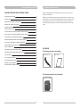
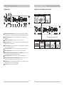
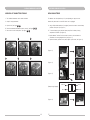
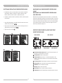
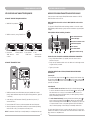
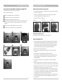
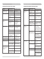
MA-808
PORTABLE WIRELESS PA SYSTEM
Portability
User Guide
Simplicity
Flexibility
All rights reserved. Do not copy or forward without prior approvals MIPRO.
Specifications and design subject to change without notice.
MN 014/08
2 CE 3 2 5 C
IMPORTANT SAFETY INSTRUCTIONS
1.
Read these instructions.
2.
Keep these instructions.
3.
Heed all warnings.
4.
Follow all instructions.
5.
Do not use this apparatus near water.
6.
Clean only with a dry cloth.
7.
Do not block any ventilation openings. Install in accordance with the manufacturer's
instructions.
8.
Do not install near any heat sources such as radiators, heat registers, stoves, or other
apparatus (including amplifiers) that produce heat.
9.
Do not defeat the safety purpose of the polarised or ground plug: A polarised plug has
two blades with one wider than the other. The wide blade is provided for your safety.
When the provided plug does not fit into your outlet, consult an electrician for
replacement of the obsolete outlet.
WARNING
1.
FOR OUTDOOR USE:
To reduce the risk of fire or electric shock, do not expose this apparatus to rain or
moisture.
2.
UNDER WET LOCATION:
Apparatus should not be exposed to dripping or splashing and no objects filled with
liquids, such as vases should be placed on the apparatus.
3.
SERVICE INSTRUCTIONS:
CAUTION - These servicing instructions are for use by qualified service personnel only. To
reduce the risk of electric shock, do not perform any servicing other than that contained
in the operating instructions unless you are qualified to do so.
This symbol indicates that dangerous voltage constituting a risk of electric shock
is present within this unit.
10. Protect the power cord from being walked on or pinched particularly at plug,
convenience receptacles, and the point where they exit from the apparatus.
This symbol indicates that there are important operating and maintenance
instructions in the literature accompanying this unit.
11. Only use attachments/accessories specified by the manufacturer.
12. Use only with a cart, stand, tripod, bracket, or table specified by the
manufacturer, or sold with the apparatus. When a cart is used, use
caution when moving the cart/apparatus combination to avoid injury
from tip-over.
13. Unplug this apparatus during lightning storms or when unused for
long periods of time.
14. Refer all servicing to qualified service personnel. Servicing is required when the
apparatus has been damaged in any way, such as power-supply cord or plug is
damaged, liquid has been spilled or objects have fallen into the apparatus, the
apparatus has been exposed to rain or moisture, does not operate normally, or has
been dropped.
15. To reduce the risk of fire or electric shock, do not expose this apparatus to rain or
moisture.
16. Apparatus should not be exposed to dripping or splashing and no objects filled with
liquids, should be placed on the apparatus.
& IC - ID
THIS DEVICE COMPLIES WITH PART15 OF THE FCC RULES AND RSS-123 ISSUE2 OF
CANADA. OPERATION IS SUBJECT TO THE FOLLOWING TWO CONDITIONS:
(1) This device may not cause interference.
(2) This device must accept any interference, including interference that may cause
undesired operation of the device. This equipment complies with FCC RF radiation exposure
limits set forth for an uncontrolled environment.
“This product can only be used at the area that the altitude is lower than 2000m for safety
purpose.”
“This product can be used in non-tropical locations only for safety purpose.”
17. Use only with the battery which specified by manufacturer.
18. The power supply cord set is to be the mains disconnected device.
19. Where the MAINS plug or an appliance coupler is used as the disconnect device, the
disconnect device shall remain readily operable.
Disposal
Dispose of any unusable devices or batteries responsibly and in accordance
with any applicable regulations.
20. Maximum operating temperature range is 50°C (122°F).
Disposing of used batteries with domestic waste is to be avoided!
Note: Battery characteristics may limit this range.
2005-08-13
Batteries/NiCad cells often contain heavy metals such as cadmium(Cd),
mercury(Hg) and lead(Pb) that makes them unsuitable for disposal with
domestic waste. You may return spent batteries/accumulators free of charge
to recycling centres or anywhere else batteries/accumulators are sold.
By doing so, you contribute to the conservation of our environment!
PORTABLE WIRELESS PA SYSTEM
PORTABLE WIRELESS PUBLIC ADDRESS SYSTEM
PORTABLE WIRELESS PA SYSTEM
MA-808 is MIPRO flagship portable wireless PA system and brings a host of impressive
features and functionalities.
PART NAMES AND FUNCTIONS
02
CONTROL PANEL
04
CONNECTION FOR EXTERNAL AUDIO SOURCES
05
OPERATION OF TRANSMITTERS STORAGE
06
REPLACING BATTERIES
07
POWER USAGE INSTRUCTION
09
SELECTION AND INSTALLATION OF WIRELESS RECEIVER MODULES
10
MRM-70/MRM-70B: UHF WIRELESS DIVERSITY RECEIVER MODULE
11
SET-UP RECEIVER AND TRANSMITTER FREQUENICES
12
WIRELESS INTERLINKING TRANSMITTER AND RECEIVER MODULES
13
MTM-90/MTM-92 COMPARTMENT FOR BODYPACK TRANSMITTER
14
INSTALLATION OF MIPRO CD/MP3 PLAYER
15
HELPFUL OPERATING TIPS
15
TROUBLESHOOTING-PORTABLE PUBLIC ADDRESS
16
TROUBLESHOOTING-WIRELESS MICROPHONE SYSTEMS
17
FAQ - PORTABLE PA
18
FAQ - RECHARGEABLE BATTERY
18
RECHARGEABLE BATTERY GUIDE
19
OPTIONAL MA-808 ACCESSORIES
20
MIPRO WIRELESS MICROPHONE SYSTEMS
21
MA-808 delivers unparalleled audio performance and craftsmanship. The rugged one-piece
speaker cabinet houses a high efficient class-D/AB amplifiers that drive high sensitivity twoway loudspeakers and limiter circuitry reduces distortion and increases intelligibility for
guaranteed powerful and clear sound. It offers an ideal public address solution for large
crowds.
ACCESSORIES
The following accessories are included:
AC Power Cord x 1
User Guide x 1
The following accessories are not included:
Storage & Carrying Bag
00
01
PORTABLE WIRELESS PA SYSTEM
PART NAMES AND FUNCTIONS
PORTABLE WIRELESS PA SYSTEM
Rear Panel
Front Panel
1
Retractable Carry Handle
(Optional)
MTM-90/MTM-92 Wireless Transmitter
MRM-72/MRM-72B Wireless Receiver Modules
2
Fixed Handle
CD Player (Optional)
3
Microphone Storage
Compartment
MRM-70/MRM-70B Wireless Receiver Modules
(optional)
8 Power Switch
9 Battery Meter Indicators
10 Control Panel
4
Treble Speaker
11 Speakon connector
12 Passive Extension Speaker Switch
13 Heat Sink
5
Bass Speaker
6
Speaker Grille
14 AC Input Socket
15
DC Input Jack
16 Battery holder
17 Trolley Wheels
7
1
8
Power Switch: Turns power on/off. The indicator glows when you turn the power on.
9
Battery Meter Indicators: 25%, 50%, 75%, 100% capacity. Charge battery
immediately at 25% (red indicator denotes low battery status) by plug the system into an
AC outlet. Regardless of length of operation, it is recommended that batteries be fully
charged as soon as possible after each use to preserve battery life.
Tripod Mount
Retractable Carry Handle: Push the handle upward from the space on the rear center
to retrieve retractable handle. Push downward to store the retractable handle.
10
Control Panel
11
Speakon connector: For connection to an external MIPRO MA-808EXP passive extension
speaker.
12
Passive Extension Speaker Switch: Push On or Off for sound output of passive
extension speaker.
2
Fixed Handle: For balanced, easy hand carrying.
3
Microphone Storage Compartment: A handy storage compartment for your handheld
or bodypack transmitters.
13
Heat Sink: Built in heat sink for amplifier. Keep the unit well ventilated when in use and
please do not touch the heat sink when in operation.
4
Treble Speaker: 1.5" Compression Driver.
14
5
Bass Speaker: 10" Neodymium Cone Driver.
AC Power Input Socket: Input socket for AC Power (100~240V)
(Various outlets fitting the standards of various countries are available for this unit)
6
Speaker Grille: To protect the internal speaker.
15
DC Input Jack: Requires external DC 24~36 volts.
7
Tripod Mount: There is a tripod mating socket mounted in the base of the MA-808 to
accommodate a 35mm tripod stand.
16
Battery Holder: Battery compartment holder is to protect the rechargeable batteries. To
install the batteries, please follow wiring diagram carefully and make sure each terminal is
connected to it's correct polarity. Please make sure that the batteries are fully charged at
all time.
17
Trolley Wheels: Heavy duty and a truly user friendly feature.
02
03
PORTABLE WIRELESS PA SYSTEM
CONTROL PANEL
A2
PORTABLE WIRELESS PA SYSTEM
CONNECTION FOR EXTERNAL AUDIO SOURCES
A4
A3
MP3 PLAYER
LINE
ON
OFF
TONE
I-POD
CD PLAYER
ECHO
IN
OUT
A1
HIGH OFF
LOW
MASTER
A5
VOICE PRIORITY
MIC 2
A6
A7
MAX
MIC 1
A8
A9
A10
A11
A12
LINE
ON
OFF
TONE
ECHO
IN
OUT
MASTER
A1
Digital Master Volume Control: Volume loudness can be remotely controlled and
wirelessly adjusted by MIPRO ACT-30Hr/ACT-32HR Handheld Transmitter Microphone.
A2
Volume Indicators: Each indicator is illuminated based on the desired volume
adjustment.
A3
LINE In Volume Control: Controls the volume of the Line Socket.
A4
Line In Socket: Allows you to use an external device with unbalanced audio output
signal as an input to the MA-808.
A5
Line Out Socket: Line level output. Allows you to use the MA-808 as a program input
source for some other audio device.
A6
Voice Priority Switch: Voice over music priority function. (factory preset: Off)
A7
Mic 2 Volume Control: Control the volume of the Mic 2 wired microphone.
A8
Wired Microphone Input Socket [6.3mm (1/4”)] Unbalanced : Allows you to use
an unbalanced, wired microphone as an input source.
A9
Mic 1 Volume Control : Control the volume of the Mic 1 wired microphone.
A10
Wired Microphone Input Socket (XLR Balanced) : Allows you to use a wired
microphone with a balanced XLR connector as an input source.
A11
TONE Control: Turn counterclockwise to increase bass or turn clockwise to increase
treble. Positioned at 12 o'clock for a flat response.
A12
ECHO Control : Adjust for desired ECHO effects .
Mixer
04
05
LOW
VOICE PRIORITY
Amplifier
MIC 2
HIGH OFF
MAX
MIC 1
Cassette Recorder
Cable Microphone (Phone-Jack)
Cable Microphone (XLR)
PORTABLE WIRELESS PA SYSTEM
PORTABLE WIRELESS PA SYSTEM
OPERATION OF TRANSMITTERS STORAGE
REPLACING BATTERIES
1.
Two handheld transmitters can be stored at MA-808.
The batteries must be replaced every 2~3 years depending on usage over time.
2.
Steps of storing transmitters.
Ascertain the power switch is turned off and AC cord is unplugged.
A.
Open the lid. (see figure: A & B )
A.
B.
Place the transmitters downward to position correctly. (see figure: C & D )
Using a Phillips-head screwdriver (not supplied) remove the screws to remove battery
protection cover panel. (see figure 1-1)
C.
Return the lid to the closed position. (see figure: E & F )
B.
To remove batteries, gently slide the battery away from the battery housing
compartment of MA-808. (see figure 1-2)
A
B
C. Replace batteries “as above” and re-connect the wires to the new batteries in
accordance to the wiring diagram below. (see figure 1-3)
C
D.
Replace the battery protection cover panel, tighten up the screws. (see figure 1-4)
(Figure 1-1)
D
E
F
(Figure 1-2)
(Figure 1-3)
black wire
(Battery wiring diagram)
red wire
(Figure 1-4)
06
07
red wire
black wire
PORTABLE WIRELESS PA SYSTEM
Please only use the following rechargeable internal battery (MIPRO MB-70 x 2 or MB-80 x 2)
or an equivalent rechargeable battery of the same type, rating & specifications when it is
required to be replaced.
Manufacturer
Kung Long Batteries Industrial Co., Ltd.
Cat No
Rating
WP4.5-12
PORTABLE WIRELESS PA SYSTEM
POWER USAGE INSTRUCTION
General Summary
!
A built-in switching power supply allows for AC power inputs ranging from 100 ~ 240volt and
an external 24~32volt DC power supply, if required.
!
A built-in AC power supply powers the unit itself and provides recharging to the built-in leadacid rechargeable batteries, too.
How to use AC power input
12 Vdc, 4.5 Ah
!
After putting the power plug into the AC input socket of the device, the 4 battery meter
indicators will glow immediately, no matter if the power switch is on or off. This means that the
built-in switching power supply is functioning normally and the built-in rechargeable batteries are
fully charged. If the battery meter indicators are blinking this means that the built-in switching
power supply is working normally and the built-in rechargeable batteries are in an under
charged condition. After a couple of minutes, the battery meter indicators will stop blinking and
continue a glowing condition, indicating the batteries are now fully charged.
!
AC power provides power to both the unit itself and to the built-in lead-acid rechargeable
batteries.
!
When using the AC power, you can remove or plug the power cord freely with no need to turn
off the power switch first. If or when an unfortunate power cut happens during usage, the MA808 will activate the DC power automatically to maintain continuous operation.
CAUTION:
!
Always change both rechargeable batteries at the same time.
!
Do not mix battery types and do not mix old and new batteries. Replace both
batteries at the same time.
!
Replace with the same type and rating rechargeable battery only.
!
Rechargeable battery can be purchased from authorized MIPRO distributors & dealers.
!
Danger of explosion if battery is incorrectly replaced.
How to use DC power input
!
Do not try to heat, ignite, disassemble or throw batteries into a fire.
!
Two built-in series connection lead-acid batteries with models WP 4.5-12 are used. When the
batteries are fully charged, the unit can be operated continuously for approximately 7~8 hours
in standby mode (CD player and two receivers are turned on); 6~7 hours for audio and 5~6
hours for music. (The above figures are references for brand new batteries only)
!
The built-in rechargeable batteries can be recharged when the unit is plugged into an AC or DC
power outlet.
!
In the case of no AC power connection, if the power switch is not turned on, the battery meter
indicators will not be shining. When the power switch is turned on, the red LED on it will be
shining; meanwhile, if 2 to 4 battery meter indicators are shining, it means the battery power is
enough for normal operation. The number of the shining indicators is in direct proportion of the
battery power. If only 1 battery meter indicator is shining or the red LED on the power switch
is sparking, it means the battery power is insufficient and immediate charge is necessary. If no
battery meter indicators are shining after the power switch is turned on, it means the batteries
are completely discharged or possibly faulty.
!
Always store MA-808 system with the batteries fully charged if needing to store the system for
more than 3 months. Leave the system plugged into an AC power outlet when not in use.
!
The rechargeable batteries will not function properly if not recharged for an extended period of
time. It is therefore, recommended to recharge after every use regardless of the usage time to
preserve battery life.
AC power and DC power can not be used at the same time.
A connector is included which allows users to make DC wiring. See diagram below for
illustration:
DC JACK Diagram
2 3
4
(Connector)
4
2
3
08
09
_
DC V
+
1
1
DC V: 24~32V/10A
PORTABLE WIRELESS PA SYSTEM
SELECTION AND INSTALLATION OF WIRELESS RECEIVER MODULES
PORTABLE WIRELESS PA SYSTEM
MRM-70/MRM-70B: UHF WIRELESS DIVERSITY RECEIVER MODULE
(SINGLE)
MRM-72/MRM-72B: UHF WIRELESS DIVERSITY RECEIVER MODULE
(DUAL SIDE-BY-SIDE)
1.
Each MA-808 can install up to 4 wireless diversity receiver modules for extended and
reliable reception: 2 MRM-70 (or MRM-70B) + 1 MRM-72 (or MRM-72B). A single
MRM-72 (or MRM-72B) consists of 2 MRM-70 (or MRM-70B) side-by-side.
2.
Installation or replacement of MRM-70 (or MRM-70B) or MRM-72 (or MRM-72B) wireless
receiver modules:
!
Using a Phillips-head screwdriver (not supplied) remove the screws to remove receiver
protection cover panel. (see figure: A & B )
!
Gently insert the receiver module into the slot. Make sure the back edge connector is
aligned and firmly connected. (see figure: C & D )
!
Tighten up the screws. (see figure E )
MIPRO offers industry-leading diversity wireless receiver module. Up to 4 wireless receiver
modules can be installed quickly and easily for wireless microphone operation. Each receiver
module has 16 preset UHF frequencies. Simply press the “scan” button once to quickly auto
scan for a clear, interference-free receiver frequency. A built-in “noise” interference indicator
(when lit) detects the presence of interference. Press scan button again to auto scan for
another clear, interference-free frequency if lit.
OPERATING THE MRM-70/MRM-70B or MRM-72/MRM-72B UHF
DIVERSITY RECEIVER MODULE
A
B
C
MRM-70/MRM-70B
B6
B7
B8
MRM-72/MRM-72B
B9
CHANNEL NOISE
RF
CHANNEL NOISE
RF
VOLUME
RF
VOLUME
SCAN
-
AF
ACT
B5
D
B4
B3
B2
B1
VOLUME
SCAN
+
-
AF
SENSITIVITY
MRM-70/MRM-70B
ACT
+
AF
SENSITIVITY
MRM-70/MRM-70B
E
10
B1
Receiver Power Switch/Volume Control : Turns on/off of receiver. After power on, AF
LED will flash. Turn knob clockwise to turn up volume.
B2
Audio Signal Meter: Indicate the audio signal level.
B3
Sensitivity Adjuster: Higher sensitivity (+) to increase receiving distance. Lower
sensitivity (-) to minimize noise interference. *note: lower sensitivity level also reduces
operating distance.
B4
ACT Infrared (IR) Port: Transmits IR signal to transmitter to synchronize frequencies.
B5
ACT Sync Button: Press to synchronize the receiver and transmitter frequencies.
B6
SCAN Button: Press for an interference-free channel.
B7
LED Screen: Displays current receiver channel.
B8
Noise Indicator: When lit, it denotes the presence of interference.
B9
RF Signal Meter: Indicate the RF signal strength received when transmitter is turned on.
11
PORTABLE WIRELESS PA SYSTEM
PORTABLE WIRELESS PA SYSTEM
SET-UP RECEIVER AND TRANSMITTER FREQUENICES
WIRELESS INTERLINKING TRANSMITTER AND RECEIVER MODULES
AUTOMATIC “RECEIVER” FREQUENCY SELECTION
Users have options to add a single MTM-90/MTM-92 wireless transmitter or MRM-72/
MRM-72B receiver module in this slot.
MRM-72/MRM-72B receiver module consists of 2 MRM-70/MRM-70B receiver modules
side-by-side.
POWER
1. POWER "ON" the portable PA
The purpose of MTM-90/MTM-92 wireless interlinking transmitter is to interlink multiple
MIPRO MA-808 portables wirelessly to greatly extend the transmission range and expand
coverage.
MTM-90/MTM-92 Wireless Interlinking Transmitter:
2. POWER on receiver by turning "VOLUME" knob.
C5
C6
VOLUME
CHANNEL NOISE
CHANNEL NOISE
CHANNEL NOISE
RF
RF
VOLUME
SCAN
SENSITIVITY
RF
VOLUME
SCAN
SCAN
AF
ACT
CHANNEL NOISE
RF
VOLUME
MRM-70-R
ACT
3. Press & hold
"SCAN" button for
1 second
SENSITIVITY
AF
MRM-70-R
ACT
4. Existing channel
blinks
SENSITIVITY
AF
MRM-70-R
5. Press & release
"SCAN" button
Power Switch/Volume Knob
C2
Channel LED Display
C3
MT-90/MT-92 transmitter module
C4
Channel-Selecting Button
C5
Power Indicator
C6
Level Limiter Indicator
C7
Bodypack Transmitter Storage
VOLUME
SCAN
AF
C1
SENSITIVITY
ACT
MRM-70-R
6. New
interference-free
channel appears
AUTOMATIC “TRANSMITTER” SYNC
C1
C2
C4
C3
C7
INSTALLATION OF MTM-90/MTM-92 WIRELESS INTERLINKING TRANSMITTER:
!
Using a Phillips-head screwdriver (not supplied) remove the screws to remove
protection cover panel.
!
Gently insert the transmitter module into the slot. Make sure the back edge connector
is aligned and firmly connected.
!
Tighten up the screws.
CHANNEL NOISE
RF
OPERATION INSTRUCTIONS OF MTM-90/MTM-92 WIRELESS INTERLINKING
TRANSMITTER:
VOLUME
SCAN
CHANNEL NOISE
RF
SCAN
ACT
SENSITIVITY
AF
VOLUME
AF
VOLUME
ACT
SENSITIVITY
Power On/Off:
MRM-70-R
<
Turn the transmitter power/volume switch C1 to ON by rotating the knob clockwise. When
ON, the power indicator C5 and Channel LED Display C2 will be lit. Rotate volume knob C1
clockwise to adjust the desired volume. Rotate same volume knob C1 counterclockwise to
power OFF the transmitter.
cm
30
(12
)
in.
Select Channels:
or
1.
POWER on transmitter (ensure fresh batteries are properly installed with the correct
polarity). Replace transmitter battery when LED glows red during powered-on. (glows red
= low battery)
2.
Locate and bring an ACT transmitter *infrared (IR) port within 30cm (12-inch) of
receiver's ACT button.
3.
Press and release “ACT” button to synchronize transmitter and receiver frequencies.
4.
When the frequencies are synchronized successfully the receiver channel stops flashing
and the RF meter is fully lit, the microphone is now ready for use.
NOTE: The transmitter infrared IR port is normally located by a round-shaped red color spot.
12
1. To select a channel one at a time: Press and hold the Channel-Selecting button C4
for around 2 seconds and release when channel LED display C2 starts flashing. Press
and release button once to move to the next available channel. If button is not
pressed again when Channel LED flashes 6 times, the channel appearing in Channel
Display is automatically saved and set.
2. To select channel continuously: Press and hold the Channel-Selecting button C4 for
around 2 seconds until channel LED display C2 starts flashing. Press and hold same
button will automatically advance channel continuously until stopped. There are a total
of 16 preset channels. If button is not pressed again when Channel LED flashes 6
times, the channel appearing in Channel Display is automatically saved and set.
The Level Limiter Indicator will not be lit under normal audio volume. If the au dio input
exceeds the set limitations, volume restriction control will activate and the indicator will lit.
Adjust volumes to an acceptable levels.
13
PORTABLE WIRELESS PA SYSTEM
MTM-90/MTM-92 COMPARTMENT FOR BODYPACK TRANSMITTER
PORTABLE WIRELESS PA SYSTEM
INSTALLATION OF MIPRO CD/MP3 PLAYER
Compartment holds and stores one body pack transmitter.
!
Using a Phillips-head screwdriver (not supplied) remove the screws to remove protection
cover panel. (see figure 2-1)
!
Gently insert the CD/MP3 player module into the slot. Make sure the back edge
connector is aligned and firmly connected. (see figure 2-2)
!
Tighten up the screws. (see figure 2-3)
Storing the body pack transmitter:
A Locate the compartment fastener on the left hand side.
B Turn fastener clockwise to loose the compartment door.
C Gently pull the compartment door away from the slot.
(Figure 2-1)
D Slide the back of the bodypack transmitter into the back of the compartment door in
position, carefully keep the antenna in horizontal position to prevent from being
squeezed.
(Figure 2-2)
(Figure 2-3)
E When secured, push in the compartment door back into the slot.
F
A
Turn fastener counter clockwise to secure the compartment door.
B
C
OPERATIONS OF CD/MP3 PLAYER:
See a separate CD player manual enclosed in the master carton.
HELPFUL OPERATING TIPS
D
E
1. We recommend placing sound system between the target audience and the presenter,
facing the audience and raised above their heads using a speaker stand or table. This
set-up helps prevent the annoying feedback by keeping wireless & wired microphone
users behind the sound system. The internal power supply rechargeable, lead-acid
batteries should be kept fully charged. Always charge the system after use.
F
2. Minimized all the volumes before powering on.
3. Each audio input is accepted through amplifier and its volume can be controlled
separately.
4. Each audio input can be broadcasted and recorded at the same time.
5. This speaker fits into a standard speaker tripod stand. For optimal usage, operate the
wireless microphones from a distance behind or beside the speaker to avoid the
undesirable feedback.
G
6. Do not expose the MA-808 to an environment where there are water dropping or
splashing.
7. Before turning power ON to the unit, please set all volume controls to their minimum
level. This prevents any loud 'thumps' at power on. Adjust the volume controls afterward.
8. NEVER place any microphone in front or close in front of the speaker otherwise damaging
feedback (both to the operators ears and the system) could occur.
9. The MA-808 features a retractable handle and wheels for easy transport. However, DO
NOT pull the unit for long distances or over uneven or rough surfaces. And, DO NOT pull
it up or down stairs. Vibration caused by long distance travel or traveling over uneven
surfaces may result in function failure not covered by warranty.
10. The MA-808-EXP extension speaker is rated at 130 watts @ 4 ohms. Please take care not
to short out the speaker cables otherwise unwarranted damage could be done to the
system amplifier.
14
15
PORTABLE WIRELESS PA SYSTEM
TROUBLESHOOTING-PORTABLE PUBLIC ADDRESS
PORTABLE WIRELESS PA SYSTEM
TROUBLESHOOTING-WIRELESS MICROPHONE SYSTEMS
PROBLEM
POSSIBLE CAUSE
SOLUTION
PROBLEM
POSSIBLE CAUSE
No Sound or Faint
Sound From Speaker
Volume turned down
Adjust volume
No Sound From
Speaker
Master or receiver volume Adjust volumes
turned down
Power switch is turned off Turn power switch on
Power Indicator Not On Power switch is turned off Turn power switch on
Distorted Sound From
Speaker
Excessive Feedback
Turn transmitter or receiver
switch on
Receiver and transmitter
have different frequencies
See “Set-up Receiver &
Transmitter Frequencies”
section
Replace or insert new
battery
Plug into AC outlet to
recharge
Rechargeable Battery is
“dead”
Replace battery and plug
into AC outlet to recharge
Volume set too high
Reduce volume
Transmitter battery is
low or no battery inside
Excessive wind noise or
breath “pops”
Use windscreen on
wireless & wired
microphones.
Headset or lavalier
Plug headset or lavalier
microphone is not plugged microphone into bodypack
into bodypack transmitter transmitter
Input signal too strong
Adjust input signals
Microphone too close or
directly in front of the
speaker
Move microphone away
from the speaker
Volume set too high
Reduce volume
Microphone too far from
Speak closer to the
sound source (requiring
the volume to be turned
up to compensate)
microphone or move
microphone closer to
sound source
Plug into AC outlet to
recharge
Excessive Hum or Noise Input Cable not shielded
Use shielded cable
Battery CHARGE
Indicator Not Flickering
when plugged into
AC Outlet
Transmitter or receiver
switch is turned off
Rechargeable Battery is
discharged
Weak, Distorted Sound. Batteries level is low
Power Indicator Flickers
Shortened Battery Life
SOLUTION
Old or overused battery
Recharge or replace
battery
Battery is not charged
for over 3~4 months
Recharge or replace
battery
Rechargeable Battery is
“dead”
Replace battery
Battery is not charged
for over 3~4 months
Recharge or replace
battery
Battery is fully charged
(CHARGE indicator is lit)
N/A
Distortion or Unwanted Interference
Noise Bursts
Noise Indicator is lit
(MRM-70/72 receiver)
(MRM-70B/72B receiver)
Remove nearby sources
of RF interference
(computers, amplifiers,
karaoke machines, digital
effects, CD players, etc)
Adjust “Sensitivity” on
MRM-70/70B/72/72B receiver
If problem persists,
change Receiver &
Transmitter frequencies.
See “Set-up Receiver &
Transmitter Frequencies”
section
Sound Dropouts
Out of operating range
Move transmitter closer
to receiver
Obstructions between the
receiver and transmitter
Remove obstructions or
reposition
Line-of-sight between
receiver & transmitter
Weak Transmitter Battery
Replace Transmitter Battery
Interference
Change Receiver &
Transmitter frequencies
See “Set-up Receiver &
Transmitter Frequencies”
section
16
17
PORTABLE WIRELESS PA SYSTEM
FAQ - PORTABLE PA
PORTABLE WIRELESS PA SYSTEM
RECHARGEABLE BATTERY GUIDE
Q: Why is my MA-808 not recharging (battery meter is not flashing)?
A: Plug one end of the included AC cord into the 12 AC Input Socket and the other end into an AC
outlet. Normal charging starts once indicators in the battery meter is flashing.
A: The built-in rechargeable batteries life has ended. Replaced with new, fresh charged batteries.
Tips - To Prolong the Life of Rechargeable Batteries
Always charge the batteries before first and after use.
Q: How to adjust for optimal sound volume?
A: If the portable system has both Master & Microphone volumes, we recommend turning the Master
volume to about 2~3pm (clockwise) first and about 1~2pm (clockwise) for Microphone or other
volumes.
Q:
A1:
A2:
A3:
A4:
A5:
A6:
Always store portable system with batteries in a fully charged condition.
Always power off the portable system and transmitter/mic when NOT in use.
How to prevent and minimize the annoying feedback?
Do not stand directly in front of the speakers; keep mics away from speakers.
Avoid pointing microphone towards the speakers.
The microphones should be behind the speakers wherever possible.
Locate the portable PA between the crowd and the presenters and facing the crowd.
Turn down the sound level coming out of the portable PA / speakers if necessary.
Place the speakers above the head of the crowd.
It is OK to leave the system plugged into a power outlet when not being used for a long time.
The built-in automatic protection circuitry will auto shut-off when fully charged. It will not harm
the system or the battery.
Fully charge the system at least once every 3 months. Battery may not charge if not charged for
a prolonged periods of time.
Q: What if I need more power to cover a larger crowd?
A: Two or more portables can be used with one wireless microphone transmitter. Ascertain that the
receiver frequency in each portable coincides with the wireless microphone.
Store in dry, cool place away from heat. Elevated temperature reduces longevity.
CAUTION: DO NOT recharge other types of batteries and connect a battery's negative terminal to
another batteries positive terminal. An explosion and/or a fire could occur as a result. Use only
rechargeable sealed lead-acid (gel cell) batteries.
Q: Can I play music through the systems?
A: Yes. All MIPRO portables have auxiliary inputs (3.5mm min-jack, RCA or 1/4”phone), which will
accept input from an external iPod, MP3, CD, cassette, VCR, DVD players. As well, modular CD
players can be inserted into most models.
FAQ - RECHARGEABLE BATTERY
Q: How to Charge the Battery?
A: Simply plug the AC power cord into an AC outlet. “Flashing” LED indicators are flashing up-anddown to denote normal charging status. The main power switch can be on or off position during
charging. Microphones or music can be used during charging & power is on.
Q: How to Spot System Low Battery?
A: When Power LED is lit (MA-705 & MA-707) or Charge LED is lit (MA-101, MA-101a, MA-101A &
MA-101B) or one indicator remaining in battery meter (MA-100, MA-202, MA-202B, MA-303, MA-505
, MA-708, MA-808). Plug into an AC outlet to re-charge immediatley.
Q: Average Life Span of Sealed Lead-Acid Rechargeable Battery?
A: The batteries should have a life of approx. 2~3 years if used and maintained properly. Battery life is
determined by temperature, depth and rate of discharge, and the number of charges and discharges
(called cycles).
Q:
A1:
A2:
A3:
A4:
When to Replace the Battery?
Power LED indicator is not “lit” when power on. (No battery voltage).
LED indicator or meter is not “flashing” when plugged-in.
Getting 1~2 hours operating time per charge.
When battery has been used extensively for 2~3 years or more.
Q: Should batteries be kept in the handheld or bodypack transmitters when not in use?
A: Do not leave old batteries in the transmitters if it will not be used for a long time. Batteries could
leak or corrode and damage the internal PCB of the transmitters.
18
19
PORTABLE WIRELESS PA SYSTEM
PORTABLE WIRELESS PA SYSTEM
OPTIONAL MA-808 ACCESSORIES
MIPRO WIRELESS MICROPHONE SYSTEMS
MA-808EXP: Extension Speaker for MA-808
MRM-70/MRM-72/MRM-70B/MRM-72B UHF 16-Channel Diversity Receiver Module
Unpowered extension speaker (10-meter speaker cable included)
(Automatic receiver frequency scan & ACT sync)
MB-70: 12V/4.5AH Rechargeable Battery
ACT-30H/ACT-32H Handheld Transmitter Microphone (AA x 2: not included)
Gell-cell (Sealed lead-acid) type rechargeable battery (MA-808 requires 2 MB-70 batteries)
MB-80: LiFePo4-LFP Battery Case
ACT-30Hr/ACT-32HR Handheld Transmitter Microphone with volume control (AA x 2: not
included)
MS-70: Speaker Tripod Stand
ACT-50T/ACT-52T Body Pack Transmitter (AA x 2: not included)
Adjustable stand for MA-808 portable PA system
SC-80: Storage Cover
(Headworn microphone is optional and not included - see below)
Storage cover and separate storage for mic cable, transmitters, microphone & battery
MU-53HN (black) ; MU-53HNS (beige) Premium Headworn Microphone
MM-107: Handheld Wired Microphone
Uni-directional, Premium 10mm, Ideal for speech and vocal. Works with all MIPRO bodypack
transmitters
MIPRO's Hypercardioid Dynamic Microphone with cable.
MU-55HN (black) ; MU-55HNS (beige) Subminiature Headworn Microphone
CDM-2: CD/USB Player
Omni-directional, 4.5mm, Sweat-proof, Ideal for speech. Works with all MIPRO bodypack
transmitters
Plays standard 12cm (5”) audio CD & MP3 CD.
DPM-3: Digital Audio Player Recorder
MU-13/MU-13d (beige) Premium Single-sided Earworn Microphone
ASP-10: Aerobic Sports Pouch
Omni-directional, ultra small & lightweight 3mm, Ideal for speech. Works with all MIPRO
bodypack transmitters
Sweat-resistant transmitter pouch belts for MIPRO bodypack transmitters
MU-23/MU-23d (beige) Premium Dual-sided Headworm Microphone
3 mm Ø omni-directional condenser microphone. Works with all MIPRO bodypack
transmitters
MU-210/MU-210d (beige) Premium Dual-sided Headworm Microphone
10 mm Ø uni-directional condenser microphone. Works with all MIPRO bodypack transmitters
(Lavalier microphone is optional and not included - see below)
MU-53L (black) ; MU-53LS (beige) Premium Lavaliere Microphone
Uni-directional, 10mm, Works with all MIPRO bodypack transmitters
MU-55L (black) ; MU-55LS (beige) Subminiature Lavaliere Microphone
Omni-directional, 4.5mm, Low visibility, Works with all MIPRO bodypack transmitters
Notes
1. Refer to actual product in the event of product description discrepancy.
2. Frequency range and maximum deviation comply with the regulations of different
countries.
20
21