1
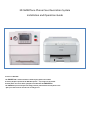
 3D SMARTone Phone Case Decoration System Installation and Operation Guide Process in a Nutshell: The SMARTone is used to decorate a wide range of phone case models. A sheet of A5 film is printed in the WP‐4015 printer.... any image can be printed. A blank phone case and a sheet of A5 film are loaded into the SMARTone. The SMARTone process transfers the image from the printed sheet into the phone cover. After just a short time to cool the case is ready for use. 3D SMARTone INSTALLATION AND OPERATION Contents: SMARTone SET‐UP AND OPERATION Section 1 Page 3 Safety instructions Section 2 Page 4 Specifications Section 3 Page 5 Installing the SMARTone Section 4 Page 5 Preparing the SMARTone for decoration Section 5 Page 7 The Control Panel and powering on Section 6 Page 8 Decorating a part Section 7 Page 12 Troubleshooting EPSON WP‐4015 PRINTER SET‐UP AND OPERATION Section 8 Page 14 Installing the Epson WP‐4015 Printer Section 9 Page 15 Printer preparation and settings Section 10 Page 19 Film Handling and making a print Section 11 Page 21 Printing from Adobe Photoshop Appendix 1 Page 25 Computer specifications 2 3D SSMARTone INSTALLATIONN AND OPERATION 1. Safetyy WAR
RNINGS Inner surrfaces become hot. Avoid touching inner su
urfaces when ho
ot. When loading and unlo
oading parts alw
ways use glovess. When loading and unlo
oading jigs always use gloves.
Do not reemove any pan
nels without dissconnecting from electricity su
upply. Only con
nnect SMARTon
ne to specified voltage supply:: 110V or 230V Operrators should w
wear cotton glovves when usingg the SMARTone since internal surfaces will b
become hot. Someething similar to the gloves picctured here is ideal. It offers aa good balance between prote
ection and functtion – you ccan still handle parts easily. Yo
ou should keep the gloves cleaan to prevent any contaminatiion of the blankk partss and film you w
will be handlingg. If the gloves b
become dirty, they should be rreplaced and are commonly availaable worldwidee at a low cost. Your SMARTon
ne comes with one pair of glovves to help you get started. Veery thickk gloves should be used for han
ndling hot jigs
Safetty Instructions SM
MARTone o
o
o
o
o
o
o
o
Printter o
o
o
o
o
o
eral Gene
o
o
o
The SMAR
RTone weighs 3
36Kg: two people should lift tthe unit Do not loo
ok directly at th
he internal ligh
hts The SMAR
RTone should b
be connected d
directly to an electrical outlet//socket; do nott use multiple o
outlets as curre
ent rating may be exceeded Only use aapproved jigs Only use aapproved phon
ne case blanks in the SMARTo
one. These are carefully desiggned to give op
ptimum decorattion performan
nce. Using non
n‐approved item
ms may risk fire
e or toxic fume
es and may dam
mage the press. Ensure ho
ot jigs are safelyy stored after rremoval Do not traansport SMARTTone with a jig installed, alwaays remove prio
or to shipping.
Do not usse solvents or fllammable liquiids near the SM
MARTone Never disassemble or atttempt to refill the ink cartridges dge if it is damaaged or leakingg Do not usse an ink cartrid
If you get ink on your skkin use soap and
d water to wassh it off es irrigate thoroughly with waater If you get ink in your eye
ead Do not force movement of the print he
urn off the printter on the fron
nt panel before disconnecting from the main
ns power Always tu
Never allo
ow children to operate the eq
quipment Keep liquiids away from the equipmentt Only use aapproved spare
es 3 3D SMARTone INSTALLATION AND OPERATION 2. Specifications Description Size Weight Packed dimensions SMARTone Self‐contained vacuum/heat press for 3D dye sublimation. Width: 375mm, Height: 400mm, Depth: 475mm 36Kg Width: 470mm, Height: 560mm, Depth: 633mm Weight: 42Kg 220‐240V 50Hz 110‐120V 60Hz 8A @ 220‐230V 15A @ 110V‐120V 2kW Built‐in Quick swap, fixed position jigs to match cases <5min <15min Voltage Current (max) Power (max) Vacuum Pump Jigs Decoration time Time to first transfer PRINTER Size Epson Workforce Pro WP‐4015‐DN Width: 460mm Height: 380mm Depth: 425mm 11Kg 110‐240V 50/60Hz 0.5A 22W Width: 620mm, Height: 480mm, Depth: 520mm, Weight: 15Kg USB 2.0 Windows XP , Windows 7 4 Colour cartridge 4800x1200 dpi 1 min/A5 sheet (approx) Black=49ml; Yellow, Magenta, Cyan 29ml Weight Voltage Current (max) Power (max) Packed dimensions Interface Driver Ink set Print resolution (max) Print speed Ink cartridge capacity CONSUMABLES Transfer film “SMARTone 3D Film”. Fast drying thermo‐formable inkjet film. A5 sheet format Wide range of “SMARTone PC Cases” 48 units per pack “SMARTone DS ink” Cases Pack size Ink Temperature and Humidity operational specification 15⁰C‐30⁰C <50% RH 4 3D SMARTone INSTALLATION AND OPERATION 3. Installing the SMARTone •
•
•
•
•
•
Remove all packing from the SMARTone Locate the SMARTone on a stable flat surface Locate the SMARTone in a well ventilated area Locate the SMARTone away from sources of dust Retain the SMARTone packaging to allow safe transportation Connect power cord to electrical outlet 4. Preparing the SMARTone Before powering on, you should fix the required support jig into the SMARTone drawer. •
•
•
•
A jig is available for each blank part model. The jig provides support for the phone cover during decoration It also ensures the correct position of the image on the case The correct jig must be used for the part to be decorated eg you must use a Samsung Galaxy S3 jig to decorate Samsung Galaxy S3 parts. No other model will fit correctly. Samsung Galaxy S3 Jig
•
The locking system ensures jigs can only be fitted one way 5 3D SSMARTone INSTALLATIONN AND OPERATION •
Line the jigg correctly with
h the locking pin
ns •
There is on
nly one way it w
will go around –
– make sure you
u push it firm
mly into place •
Push firmlyy to left to lockk You can sw
wap out the jig at any time. •
•
Wearing th
hick gloves, dislodge the jig byy pushing it to tthe right and ffit the new jig in
nto place. •
•
Press the ‘NEST WAR
RM’ button on the screen The b
button will turn red until the jigg is heated Use thickk gloves when lloading and unlloading jigs e place as it will remain hot fo
or some time If a hot jig is removed from the SMARTTone ensure it is kept in a safe
6 3D SMARTone INSTALLATION AND OPERATION 5. The Control Panel and powering on •
•
•
•
•
Flick the red power switch to start the SMARTone The SMARTone will now begin a ‘warming up’ cycle to bring the drawer and jig up to operating temperature. Initial warm‐up will take around 15 minutes. The SMARTone will not run a decoration cycle unless it is at operating condition. Once at operating condition the SMARTone will maintain this so that it is ready to use, even if you leave it idling for an extended period of time. To ensure that the press is always ready keep the drawer closed when not in use. 7 3D SMARTone INSTALLATION AND OPERATION 6. Decorating a part •
•
When you are ready to decorate a part, open the drawer. Here is a look at the drawer in detail. •
The platen and jig will become hot during the process. •
•
This is the frame. This is used to clamp the film into place. Raise it to load film. •
•
When the frame is down, it rests against a silicon foam seal. Take care not to cause damage to the seal – replacements can be fitted easily if necessary. •
•
•
Clip the blank phone case onto the jig. The top of the part should always go to the left hand side (camera holes are normally located at the top). Extra care should be taken to ensure that the case is clipped on in this way. 8 3D SMARTone INSTALLATION AND OPERATION •
The case should fit tightly onto the jig. •
Press all around the edges to make sure the part is securely in place. •
Do not leave the part in the press for more than 20 secs before adding the film and starting the cycle to prevent possible part distortion. •
Load the film ‐ print side down and ‐ top of the print to the left. ‐ Print templates supplied with the SMARTone system will feature a red dot in the top left corner of the print, so that orientation can be easily identified on the printed sheet of film. This also denotes the corner of the film that is to be used for registration as shown in the illustration to the left. It is recommended that a similar mark is used if you are making your own templates. •
Close the frame Push the drawer firmly closed •
As soon as the film is loaded close the drawer. The film may distort if this procedure is not done quickly •
Press the Cycle Start button. •
The SMARTone will now take care of everything. Caution – be careful not to run a cycle with printed film but no part, as the dye will be transferred onto the surface of the jig and then will be transferred to the inside of the next parts you run. If this happens remove the jig from the drawer and allow it to cool. The jig can be gently cleaned with water and a scouring pad (eg 3M Scotch‐Brite green) 9 3D SMARTone INSTALLATION AND OPERATION •
The screen will show the process timer counting down The dial will show the vacuum level. •
NB: the vacuum level will pulse in the initial stages of the cycle •
When complete, a buzzer will sound and the drawer can be opened. •
•
Remove the film and unclip the part. SMARTone part removal tool is recommended •
The part will cool quickly and can then be used/packaged for sale straightaway. •
The SMARTone is ready for its next cycle. •
Either load the next part or close the drawer to keep warm. The keep warm cycle starts 2 minutes after the drawer is closed if the start button has not been pressed. 10 3D SMARTone INSTALLATION AND OPERATION If you need to change between cycle programs: Press ‘Prog Select’ on the screen. The Program Selection menu will appear. Use the arrows to choose the program you require, then press ‘Process’ to return to the main screen. You can now continue as normal using the program you have selected. 11 3D SMARTone INSTALLATION AND OPERATION 7. Troubleshooting •
The part is difficult to remove from the jig It is easiest to remove the part from the jig whilst it is still hot as the plastic will tighten as it cools. Ensure that a part is not allowed to go cool on the jig as it will become difficult to remove. If this happens, simply close the drawer and start a cycle, allow around 15 seconds then abort the cycle by pressing the stop button and then the part can be removed. By prising gently at the corners of the front edge the part will unclip easily. •
There are white spots on the finished part The SMARTone process relies on good contact being made between the printed film and the surface of the part during the cycle. Small white dots or fine lines on the finished part point to some dust or other particles obstructing this contact. Solution: Ensure that film is printed only as required or sufficiently protected so that dust cannot gather on the surface. Wipe the blank part before use with a clean, lint‐free cloth. As the part is white, contamination will be visible on close inspection, so should be cleaned off adequately. •
The decoration looks weaker than expected and/or appears blotchy The ink on the film is not dry. Each print will require some drying and there is a handy drying frame on top of the SMARTone for this purpose. Film should be placed in this drying frame print side up with the long edge of the film facing away from the operator i.e. the film is clipped into the tray bowing upwards to allow air circulation. A minimum of 2 minutes is sufficient to dry most printed sheet. For darker images that have a relatively high ink load 3 minutes is recommended. •
The vacuum drops suddenly during a cycle Allow the cycle to finish – do not abort as the quality of transfer may not be affected depending on how well vacuum held initially. •
Ensure film is properly clamped by the frame •
Ensure seal is not damaged – replace if required •
Ensure jig is properly clipped into place and is not damaged If the jig has been significantly damaged and cannot be thoroughly repaired then a replacement should be purchased to avoid further wastage of film and parts. 8. Maintenance The SMARTone is designed to require minimum maintenance if operated according to the instructions. If you notice a persistent decrease in vacuum level or reduction in decoration quality, contact your supplier for advice. 12 3D SSMARTone INSTALLATIONN AND OPERATION EPSON W
WP‐4015 PR
RINTER SEET‐UP AND
D OPERATION 8. Installing the Ep
pson WP‐4
4015 Printter Remove aall packaging acccording to insttructions suppllied with the prrinter Locate the
e printer on a sstable flat surfaace Locate the
e printer in an environment 1
15‐30C, <50% RH Locate the
e printer away from sources o
of dust •
•
•
•
nks. Only usee SMARTone in
Other inks, including Ep
pson own brand
d, are not comp
patible with the
e decoration pro
ocess. Non‐ SM
MARTone inks may damage thhe printer. 13 3D SSMARTone INSTALLATIONN AND OPERATION 9. Printer preparation and ssettings Printer front paanel: wing when turrning on the p
printer for firsst time: Do the follow
Load inks: L
Open front cove
O
er Remove ink cart
R
tridges from paackaging Insert accordingg to instructionss on cover NB green chip is loca
N
ated at top of cartriidge Close the cover C
and allow the printer to load the inks. Ink loading will take approx 5 m
minutes NB Do not turn off p
N
printer during this p
process 14 3D SSMARTone INSTALLATIONN AND OPERATION Use the ‘multi‐p
U
purpose’ tray att the rear. Fold the clear co
F
over forward. Pull up fully to l
P
ock in place. Film guides are F
self‐centering .. Put a sheet of A
P
A5 in tray and push guides until just touching each edge. e
The film should T
be flat and nott bowed by the guides. Load plain A4 pa
L
aper into the frront cassette. This is used to c
T
check the printing Pull out cassette
P
e, load paper and return casse
ette. Fully extend the
F
e output tray to
o catch printed film. NB: ensure that
N
t the print tray will not get kno
ocked when extended. e
Make a nozzle c
M
check to ensuree ink is loaded ccorrectly: Turn o
off printer (if tu
urned on) 2)
Hold d
down the colou
ur nozzle clean button and preess the po
ower button. 1)
A test pattern w
A
will be printed (using plain pap
per from the fro
ont cassette). c
15 3D SMARTone INSTALLATION AND OPERATION If segments are missing the print nozzles need cleaning. Press the appropriate nozzle clean button: ie if magenta, yellow or cyan are affected press the colour nozzle button, if black is affected press the black nozzle button NB Nozzle checks and cleaning can also be run from driver software Once the printer is set up load the driver software following the instructions in the Epson documents. USE USB CONNECTION Accept the default settings. Note: decline any requests for registration or updates from Epson. Once the driver is installed it must be configured. Right click on printer and select ‘Printing Preferences’ Windows XP Windows 7 3) All the segments of test lines should be present As shown on left 16 3D SMARTone INSTALLATION AND OPERATION Configure Main page like this: 1 Paper Source= Rear MP Tray 2 Document Size= A5 3 Orientation=Portrait 4 Paper type=plain paper 5 Quality=Quality Other settings should be default Configure More Options page like this: 1 High speed=unchecked 2 Mirror Image=checked 3 Edge Smoothing=checked 4 Color Correction= Custom Then click ‘Advanced.....’ 17 3D SMARTone INSTALLATION AND OPERATION NB This method is for printing via Photoshop In Color Correction select No Color Adjustment. Then click OK to close color correction Finally, click OK to close the preferences dialogue. These settings will now be active when printing from an application. 18 3D SMARTone INSTALLATION AND OPERATION Note: it is possible to print nozzle checks and run nozzle cleaning from the Maintenance page. To install the ICC profile: Right click on file and click ‘Install Profile’ from menu. The profile is then copied into the operating system. 10.Film Handling and making a print Store film in packet and re‐seal when not required. Avoid touching the printing area of the film surface. It is only possible to print on the matte side of the film. 19 3D SSMARTone INSTALLATIONN AND OPERATION Place film in printer with print (mattte) side facing forward. me. If multiple ssheets are loaded it Only load one sheet of film at a tim
ough the printeer. is posssible more than one sheet will be pulled thro
Once printed take caare not to damaage film surface
e. The in
nk will be wet o
on the surface aand needs a few
w minutes to drry. Alwayys keep film printed surface up
pwards. Avoid
d stacking the printed sheets. There
e is a drying fram
me built into th
he top of the prrinter. he manner show
wn here. It is best to load the film sheet in th
20 3D SMARTone INSTALLATION AND OPERATION 21 3D SMARTone INSTALLATION AND OPERATION 11. Printing from Adobe Photoshop Set‐up Photoshop to apply profile. NB versions of Photoshop differ in the layout however:‐ 1) Select Printer= Epson WP‐
4015 (it should be default) 2) Select ‘Color Management’ 3) Select Color Handling= Photoshop Manages Colors 4) Select Printer Profile= SMARTone Epson 4015 profile NB scroll down list 5) Select Rending Intent=Perceptual 6) Either click ‘Done’ to exit and save settings or press ‘Print’ To print: Enter the print dialogue. Check principle setting are applied as above Check orientation of image is correct in preview Here the print orientation is WRONG. Click the icon at the bottom set correct orientation 22 3D SMARTone INSTALLATION AND OPERATION By clicking the button at the bottom the orientation is corrected. NB you can also rotate the orientation in Photoshop and keep the print setting constant. Press Print button in Photoshop. Press the Print button in Photoshop The print dialogue box will open. Confirm that the Epson WP‐4015 is the target printer. If necessary check the preferences are set correctly. The number of copies can also be set here. Load a sheet of film in to the printer 23 3D SMARTone INSTALLATION AND OPERATION and press ‘Print; If film is not loaded the feed light will illuminate on the printer. In this case load a sheet and press the feed button. The print will then continue. If multiple copies are being made, allow each sheet to complete before loading the next. Use the feed button until all the copies are completed. 24 3D SMARTone INSTALLATION AND OPERATION If you wish to cancel a print job press the ‘trash can’ button APPENDIX 1 Windows (Minimum requirements) •
•
•
•
•
•
•
Intel® Pentium® 4 or AMD Athlon® 64 processor Microsoft® Windows® XP with Service Pack 3 or Windows 7 with Service Pack 1. 1GB of RAM 1GB of available hard‐disk space for installation; additional free space required during installation (cannot install on removable flash storage devices) 1024x768 display (1280x800 recommended) with 16‐bit color and 256MB (512MB recommended) of VRAM OpenGL 2.0–capable system DVD‐ROM drive Broadband Internet connection may be required for software activation, validation of subscriptions, and access to online services. 25