1
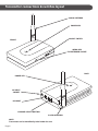
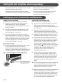
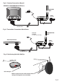
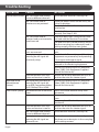
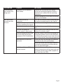
5.8GHz Wireless AV Sender System
27998R
USER GUIDE
Philex Customer Careline 08457 573479
Introduction
Congratulations on your purchase of the SLx 5.8GHz
Wireless AV Sender System. This product has been
designed to allow an audio/video signal from
equipment such as DVD players, Digital TV receivers,
Satellite Receivers and VCRs to be both watched and
controlled in a different room without the need for
runs of cable or DIY!
The receiver can work within 30 metres of the
Transmitter depending on the building structure and
is supplied with an Infra-Red Extender & an Infra-Red
Receiver allowing you to control your
equipment from a different room.
In this day and age, more and more equipment is becoming wireless. To prevent interference from neighbouring AV senders, wireless routers, DECT phones etc
this system works transmitts on the 5.8GHz frequency
which makes the system is not affected by interference from standard wireless equipment. There are also
3 operating channels to choose from allowing you to
select the channel with the least interference.
Before attempting to install the system, please read
through the instructions carefully ensuring you understand the procedure and have all items necessary.
Sender system components
NOTE:
The transmitter and receiver
can be identified by the label
on the base.
TRANSMITTER
RECEIVER
WIRELESS
TRANSMITTER
CABLE
WIRELESS
RECEIVER
CABLE
INFRA-RED
EXTENDER
INFRA-RED
RECEIVER
POWER ADAPTORS x2
Page 1
Transmitter connections & switches layout
5.8GHz ANTENNA
POWER LED
ON/OFF SWITCH
FRONT
PO
W
ER
INFRA-RED
EYE EXTENDER SOCKET
F
OF
ON
IR-T
BACK
POWER LED
PO
ER
W
AV INPUT
SOCKET
AV
IN
DC
7.5
V
DC INPUT
CH
AN
NE
L
AN
T
CHANNEL SELECT BUTTON
5.8GHz ANTENNA
NOTE:
Transmitter can be identified by label under the unit
Page 2
Receiver connections & switches layout
5.8GHz ANTENNA
POWER LED
ON/OFF SWITCH
FRONT
PO
W
ER
INFRA-RED
RECEIVER SOCKET
F
OF
ON
IR-R
BACK
POWER LED
PO
ER
W
AV OUTPUT
SOCKET
AV
O
UT
DC INPUT
DC
7.5
V
CH
AN
NE
L
AN
T
CHANNEL SELECT BUTTON
5.8GHz ANTENNA
NOTE:
Receiver can be identified by label under the unit
Page 3
Getting the best reception and saving energy
• Both the AV Transmitter and Receiver units should be placed on flat, stable surfaces.
• Minimise the number of obstacles between the AV Transmitter and Receiver.
• Rotate the 5.8GHz Antenna on the Transmitter and Receiver so they are standing up at 90 degrees.
• For energy saving purposes please switch off all your AV equipment when not in use, including the 5.8GHz AV Sender.
Setting up your Transmitter and Receiver
CONNECTING THE RECEIVER
(Connects to 2nd TV (e.g. in Bedroom or Kitchen)
1) Plug the 3.5mm Jack end of the ‘Wireless Receiver Cable’ into the AV OUT socket on the Receiver.
Ensure that the 3.5mm JACK is plugged all the way into
the AV OUT socket.
CONNECTING THE TRANSMITTER
(Main viewing room, e.g. Sitting Room)
2)Plug the Scart end of the ‘Wireless Receiver Cable’
into the Scart input on the television located in
the receiving room - (See Fig. 2)
6) Plug the Scart end of the ‘Wireless Transmitter Cable’ into the Scart output socket on your AV
source equipment (satellite receiver, VCR or DVD).
3) Connect one of the power adaptors to the DC
input on the Receiver as shown in Fig. 2. Plug the
power adaptor into a mains socket and switch the
socket ON, the Power LED should come on. If the
LED does not light up, ensure that the ON/OFF
switch on the Receiver is set to ON.
7) Plug the Infra-Red Extender cable into the Infra
Red Socket on the Transmitter as shown in Fig. 3.
INFRA-RED RECEIVER
4) Position the INFRA-RED RECEIVER on top/in front of your television or any other location in
direct line of sight with your remote controls
(See Fig.1). Use the adhesive pad supplied to hold
it in place when you are happy with the position.
Fig. 1 -Positioning the Infra-Red Receiver
Infra-Red Receiver
Note: Attach with supplied
Sticky-Back Velcro Pad
5)
8) Plug the 3.5mm Jack end of the ‘Wireless Transmitter Cable’ into the AV IN socket on the Transmitter.
Ensure that the 3.5mm Jack is plugged all the way in to
the AV IN socket.
Position one of the Infra-Red Eyes on the Infra-
Red Extender lead in front of the infra-red sensor
window of your AV source equipment (satellite
receiver or VCR or DVD). The infra-red sensor
window on some satellite receivers is marked
by this symbol
. Make sure the curved surface
of the Infra-Red Eye is facing the sensor window
as shown in Fig. 4 and (For further tips on
locating the Infra-Red sensor window see
Troubleshooting section).
9) Connect
the remaining power adaptor to the
DC input on the Transmitter as shown in Fig. 3.
Plug the power adaptor into a mains socket and switch the socket ON, the Power LED shall now be lit. If the LED does not light up, ensure that
the ON/OFF switch on the Transmitter is set
to ON.
10) On the back of both the Transmitter and Receiver
are 3 channel switches. Ensure that the same
channel switch on both the Transmitter and
Receiver are set to the same number.
11)Select an appropriate AV channel on the receiving
television. The television should now show
whatever signal the Transmitter is sending and if
the infra red eye is properly positioned you will
be able to control the AV source by pointing the
correct remote control at the AV Receiver.
Page 4
Fig. 2 - Receiver Connections Room 2
SECOND TV (BEDROOM/KITCHEN etc.)
RECEIVER
UNIT
INFRA-RED
RECEIVER
POWER
ADAPTOR
SCART INPUT
AV IN
DC 7.5V
CHANNEL
ANT
WIRELESS
RECEIVER CABLE
Fig. 3 -Transmitter Connections Main Room
TRANSMITTER
UNIT
INFRA-RED
EXTENDER
(see Fig. 3 for positioning)
SAT, DVD, DVBT etc
POWER
ADAPTOR
SCART OUTPUT
AV IN
DC 7.5V
CHANNEL
ANT
WIRELESS
TRANSMITTER CABLE
Fig. 4 -Positioning the Infra Red Eye
SATELLITE
Infra red eyes
Make sure the curved surface of the infra
red eye is facing the sensor window
Page 5
Troubleshooting
Problem
Cause
PROBLEM
CAUSE
No Picture or Sound The Transmitter and receiver
are set to different channels
The Transmitter and/or
Receiver are not powered
The Transmitter and/or
Receiver Leads are incorrectly
fitted/reversed
Transmitter and/or Receiver
Units are reversed
The equipment providing or
receiving the AV signal are
incorrectly setup
Distance between the Transmitter and receiver is too far
Black and White
The equipment providing or
(Monochrome
receiving the AV signal are
Picture)
set to RGB, Component Video,
SVHS S Video, DVI or HDMI
Poor Picture Quality Interference from microwaves
ovens.
Obstruction to signal
Distance between the Transmitter and receiver is too far
The Transmitter and receiver
are set to different channels
The equipment providing or
receiving the AV signal are
incorrectly set
Page 6
Action
ACTION
Set to identical channels (See step 10)
Check the power switch on the unit(s) are
in the On position
Check that the Mains Electrical power is
switched on
Check the Mains adaptors are fitted
correctly (See Steps 3 & 9)
Swap over both leads so the correct leads
are used with the Receiver/Transmitter
The leads are not inserted correctly, ensure
that the scart plug has no bent pins and it
making contact with the scart socket
Swap over the Transmitter and Receiver
units
Check that the Transmitting and Receiving
Equipment are powered up and providing
a Scart Input and output signal
Ensure that correct Scart input has been
selected on the Receiving equipment
Set the Scart output/input to Composite
Video (CVBS) (See Equipment Suppliers
Manual for how to set)
Reduce the distance between the units or
position the units for a better signal
Set the Scart output/input to Composite
Video (CVBS) (See Equipment Suppliers
Manual for how to set)
Move Transmitter/Receiver away from
microwave.
Place away from walk ways or walk through
areas
Place away from Thick walls, masonry or
metalwork
Reduce the distance between the units or
position the units for a better signal
Set to identical channels (See step 10)
The Leads are not inserted correctly, ensure
that there are no bent pins in the scart plug
and it making contact
PROBLEM
CAUSE
ACTION
All the available
scart sockets are
being used
Equipment has insufficient
scart sockets
Infra red remote
control does not
function
Infra-Red Eyes set up
incorrectly
Sunlight or high output
lighting is blocking the Signal
Incorrect Remote used
Purchase an unswitched scart splitter
for the transmitting equipment and/or a
switched scart selector for the receiving
equipment
Connect equipment using other connector
type e.g. Coax flylead
Infra red transmitting and/or receiving eyes
are not positioned correctly (See Step 8)
Block the excessive light
Infra red Transmitter or
receiver signal is obstructed
Difficulty finding the Infra red
sensor on the Transmitting
Equipment (DVD, Satellite etc)
Intermittent or no Infra red
operation
Cable Box which use IRDA
Remote controls
Use Original or compatible Remote controls
Remove obstruction and position the Infra
red eyes for a better signal
(See Figs 4 and 8) and use a second person
aiming the remote control at the AV Receiver while the first person moves the Infra red
eyes in front of the Transmitting Equipment
Check that the Infra red leads are correctly
inserted into the Infra red Socket(s)
Check the remote works directly with the
Transmitting equipment and that the batteries are not discharged
Some cable boxes use an IRDA remote
control system these will not work with you
AV sender (Contact your Cable supplier to
see if your box uses IRDA
Page 7
For further information or any queries, please contact
Philex Customer Careline: 08457 573 479
(Local rate – UK only)
Technical Support: [email protected]
1856
Declaration of Conformity available at:
http://technical.philex.com
Waste electrical products should
not be disposed of with household
waste. Please recycle where
facilities exist. Check with your Local
.Authority for recycling advice
Page 8
© Philex Electronic Ltd. 2008 v1.1