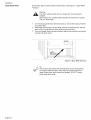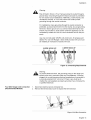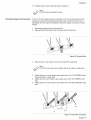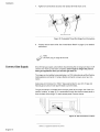
1
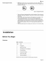
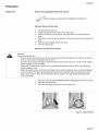
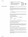
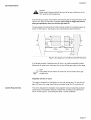
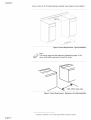
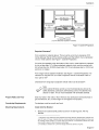
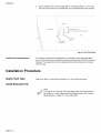
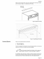
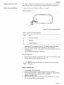
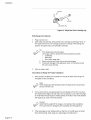
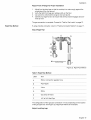
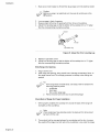
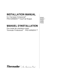
Installation
Instructions
Bosch Dual Fuel Range
Slide-In Model
Table of Contents
Safety ......................................................
1
Installation
3
.................................................
Before You Begin .............................................................
Installation Procedure ..........................................................
3
8
Service ...................................................
18
Before Calling Service .........................................................
18
Questions?
1-800-944-2904
www.boschappliances.com
5551 McFadden Ave.
Huntington Beach, CA 92649
We look forward to hearing
from you!
Safety
IMPORTANT SAFETY INSTRUCTIONS
READ AND SAVE THESE INSTRUCTIONS
Important Safety
Instructions
Appliance Handling Safety
WARNING: Do not repair or replace any part of the appliance unless specifically recommended in the manuals. Improper installation, service or maintenance can cause injury or property damage. Refer to this manual for
guidance. All other servicing should be done by a qualified technician.
•
•
•
Safety Codes and Standards
•
•
•
Electric Safety
•
•
•
•
•
•
•
Do not lift appliance by door handle. Remove the door for easier handling and
installation. See instructions in Use and Care Manual.
Unit is heavy and requires at least two people or proper equipment to move.
Hidden surfaces may have sharp edges. Use caution when reaching behind
or under appliance.
This appliance complies with one or more of the following Standards:
•
UL 858, The Standard for the Safety of Household Electric Ranges
•
UL 923, The Standard for the Safety of Microwave Cooking Appliances
•
UL 507, The Standard for the Safety of Electric Fans
•
ANSI Z21.1-2000, The American National Standard for Household Cooking Gas Appliances
•
CAN/CSA-C22.2 No. 113-M1984 Fans and Ventilators
•
CAN/CSA-C22.2 No. 61-M89 Household Cooking Ranges
It is the responsibility of the owner and the installer to determine if additional
requirements and/or standards apply to specific installations.
Installation must conform with local codes or, in the absence of local codes,
with the National Fuel Gas Code, ANSI Z223.1.
The appliance must be electrically grounded in accordance with local codes
or, in the absence of local codes, with the National Electrical Code ANSI/
NFPA 70, latest edition. (In Canada, installation must be in accordance with
the CAN 1-B149.1 and .2 Installation Codes for Gas Burning Appliances and/
or local codes)
Before you plug in an electrical cord, be sure all controls are in the OFF position.
For appliances equipped with a cord and plug, do not cut or remove the
ground prong. It must be plugged into a matching grounding type receptacle
to avoid electrical shock. If there is any doubt as to whether the wall receptacle is properly grounded, the customer should have it checked by a qualified
electrician.
If required by the National Electrical Code (or Canadian Electrical Code), this
appliance must be installed on a separate branch circuit.
Only a power-supply cord kit rated for this appliance and marked "for use with
ranges" shall be used.
Installer - show the owner the location of the circuit breaker or fuse. Mark it for
easy reference.
Important - Save these instructions for the local electrical inspector's use.
Before installing, turn power OFF at the service panel. Lock service panel to
prevent power from being turned ON accidentally.
English 1
,_Safety
Gas Safety
•
Be sure your appliance is properly installed and grounded by a qualified technician. Installation, electrical connections and grounding must comply with all
applicable codes.
•
Install a gas shutoff valve near the appliance. It must be easily accessible in
an emergency.
Leak testing must be conducted by the installer according to the instructions
in this manual.
The appliance and its individual shutoff valve must be disconnected from the
gas supply piping system during any pressure testing at pressures in excess
of ½ psi (3.5 kPa)
The appliance must be isolated from the gas supply piping system by closing
its individual manual shutoff valve during any pressure testing of the gas supply piping system at test pressures equal to or less than ½ psi (3.5 kPa)
The minimum supply pressure must be 1" water column above the manifold
pressure printed on the data plate:
The maximum supply pressure must not exceed 14.0 inches water column
(34.9Millibars).
•
•
•
•
•
WARNING: If the information in this manual is not followed exactly, a fire or
explosion may result causing property damage, personal injury or death.
Do not store or use combustible materials, gasoline or other flammable
vapors and liquids in the vicinity of this or any other appliance
WHAT TO DO IF YOU SMELL GAS:
•
Do not try to light any appliance.
•
Do not touch any electrical switch.
•
Do not use any phone in your building.
•
Immediately call your gas supplier from a neighbor's phone. Follow
the gas supplier's instructions.
•
If you cannot reach your gas supplier, call the fire department. Installation and service must be performed by a qualified installer, authorized service agency or the gas supplier.
Figure 1: Gas Precautions
This appliance has been CSA certified for safe operation up to a height of
10,000 ft. without any modifications. Exception: For use with propane the
appliance must be converted per the LP conversion instructions.
For Massachusetts installations:
•
Installation must be performed by a qualified or licensed contractor,
plumber or gas fitter qualified or licensed by the state, province or region
where this appliance is being installed.
•
Shut-off valve must be a "T" handle gas cock.
•
Flexible gas connector must not be longer than 36 inches.
•
Installer - show the owner where the gas shut-off valve is located.
Propane Gas Installation
English 2
The propane gas tank must be equipped with its own high pressure regulator.
In addition, the regulator supplied with this unit must also be used.
The appliance is shipped from the factory for use with natural gas. It must be
converted for use with propane. A qualified technician or installer must do the
conversion.
,_
Related Equipment Safety
•
Safety
Warning: All ranges can tip. Injury to persons could result. Install anti-tip
device packaged with range. Verify that the anti-tip devices are engaged. See
installation instructions.
Figure 2: Tipping Precautions
•
Remove all tape and packaging before using the appliance. Destroy the packaging after unpacking the appliance. Never allow children to play with packaging material.
Never modify or alter the construction of the appliance. For example, do not
remove leveling legs, panels, wire covers or anti-tip brackets/screws.
To eliminate the risk of burns or fire by reaching over heated surface units,
cabinet storage space located above the surface units should be avoided. If
cabinet storage is to be provided, the risk can be reduced by installing a hood
that projects horizontally a minimum of 5 inches beyond the bottom of the
cabinet.
•
•
•
Verify that cabinets above the cooktop are a maximum of 13" (330 mm) deep.
Installation
Before You Begin
Overview
Table 1: Overview
Step
Task
1.
Preparation
2.
Apply Foam Tape
3.
Install Backwall Trim (Optional)
4.
Connect Electric
5.
Connect Gas Supply
6.
Test for Gas Leaks
7.
Test the Installation
Proceed to the sections that follow for step-by-step instructions.
English 3
Installation
Tools and Parts Needed
Range Power Supply Cord Kit (240V -30 Amp)
Note: Not necessary for Canadian installations; Canadian units are shipped
with the power cord already installed.
Measuring Tape
Phillips Head Screwdriver
1-1/4" (31.8 mm) Wrench
Pencil
T-20 Torx Screwdriver
Screws (2) and Anchors (2) for Anti-Tip Bracket (Style will vary depending on
mounting surface)
Level
Drill and Drill Bit
Soapy Water
Pipe Wrench
Teflon Tape
Channel Lock Pliers
Gas Leak Test Solution
Gas Supply Line
Gas Shut Off Valve
Safety Gloves and Goggles
Tape (Optional)
Cloth or Cardboard (Optional - to Protect Floor)
Additional Parts Needed For
Hard Wire Installations
•
•
•
Flexible Conduit
Torque Wrench
Note: Power Supply Cord Kit Not Necessary For Hard Wire Installations
Parts Included
•
•
•
•
•
Anti-Tip Bracket
Foam Tape
Backwall Trim
Screws for Backwall Trim (2)
Terminal Lugs (For Use With Hard Wire Installations)
Note: not necessary for Canadian installations
General Information
Overall Dimensions
Table 2: Overall Dimensions
Level
English 4
Dimension
Inches
centimeters
Height
36"
91.44 cm
Width
31"
78.74 cm
Depth
25 5/8"
65.09 cm
For best results, cabinets, countertops walls and floors in the installation location
should be as level and plumb as possible. Variance may cause damage to countertops and floors during installation, could jeopardize the seal around the cooktop
and may adversely affect cooking and baking performance.
Installation
Preparation
Prepare Unit
Remove all packaging material and discard.
Tip:
Place the range on a piece of the cardboard to protect floors.
Remove drawer and set aside.
1.
2.
3.
4.
5.
6.
Pull drawer all the way out.
Locate locking clips on the rails, one on each side.
Push up on the clip on the left rail. Pull the drawer out until clip locks into
place.
Push down on the clip on the right rail. Pull the drawer out until clip locks into
place.
Pull the drawer straight out and set aside.
Push rails into range.
Remove oven door and set aside.
,_
When removing the door:
Warning:
•
Make sure oven is cool and power to the oven has been turned off before removing the door. Failure
to do so could result in electrical shock or burns.
•
•
•
•
The oven door is heavy and fragile. Use both hands to remove the oven door. The door front is glass.
Handle carefully to avoid breaking.
Grasp only the sides of the oven door. Do not grasp the handle as it may swing in your hand and
cause damage or injury.
Failure to grasp the oven door firmly and properly could result in personal injury or product damage.
To avoid injury from hinge bracket snapping closed, be sure that both levers are securely in place
before removing door. Also, do not force door open or closed - the hinge could be damaged and
injury could result.
1.
2.
3.
Be sure to read the above WARNING before attempting to remove oven door.
Open the door all the way.
Flip levers on hinges (one on each side) toward you.
Figure 3: Hinge Positions
English 5
Installation
4.
5.
6.
Electrical Requirements
Close the door until it stops. It will be about halfway open.
Holding the door firmly on both sides and using
both hands, pull the door straight out of the
hinge slots. Hold firmly, the door is heavy.
Place the door in a stable location.
Refer to data plate for more information. See "Product Data Plate" on page 23 for
data plate location.
We recommend that the range be installed with a power cord set (not supplied).
The electrical rating of the power cord set must be 120/240 volt, 30 amperes minimum. The power cord set shall be marked "For Use with Ranges." Always use a
new power cord.
Note:
In Canada, the range is shipped from the factory with the range cord
already installed.
Ranges are dual rated for use on either 120/240 VAC or 120/208 VAC. Check the
data plate for the kW rating. Reference the kW rating in the table below to determine amperage requirements.
Table 3: Electrical Specifications
kW Rating
120/240V
120/208V
6.2
4.8
Hz
Amps Req'd
60
30
The electrical outlet must be located in the shaded space shown in "Gas Supply
Line and Electrical Outlet Placement" on page 7.
Verify that wiring to house is adequate
Contact your local utility company to verify that the present electric service to your
home is adequate. In some instances, the size of the wiring to the house and service switch must be increased to handle the electrical load demanded by the
range.
Verify that wiring inside house is adequate
Most wiring codes require a separate circuit with separate disconnect switch and
fuses either in the main entrance panel or in a separate switch and fuse box.
The range requires a minimum of a three wire 120/240 or 120/208 volt, 30 AMP,
60 Hz AC circuit. Check local codes for proper amperage ratings. A four wire connection is preferred.
Most local building regulations and codes require that electrical wiring be done by
licensed electricians. Be sure to install your range according to the electric codes
in place in your region.
English 6
Installation
Gas Requirements
_k_
Make
cauti°n:certain that gas shutoff valve and all burner controls are in the
OFF position before beginning.
Shut off main gas supply valve before disconnecting the old range and leave it off
until the new hook-up has been completed. Don't forget to relight the pilot on
other gas appliances when you turn the gas back on.
The gas supply line and electrical outlet must be located in the shaded space as
shown in See Figure 4: Gas Supply Line and Electrical Outlet Placement.
131/8"
(.333rnrn)
(98mrn)
3d'
(762 ram)
41/2"
114.3rnm
Figure
4: Gas Supply
Line
and Electrical
Outlet
Placement
If not already present, install gas shut off valve in an easily accessible location.
Make sure all users know where and how to shut off the gas supply to the range.
Note:
The installer should inform the consumer of the location of the gas
shutoff valve.
Important note for LP users
The range is shipped from the factory for use with natural gas. For use with propane (LP) gas, your range must first be converted using the LP conversion kit.
Cabinet Requirements
This unit is designed for installation near adjacent walls and projecting surfaces
constructed of combustible materials. Prepare the countertop and cabinets as
shown in See Figure 5: Cutout Requirements - Typical Installation.
English 7
Installation
Allowa minimumof30inchesbetweencabinetswhererangeisto beinstalled
1..
_.
.....
F_ .
30" _£16_
...........
Figure 5: Cutout Requirements - Typical Installation
Note:
The slide-in range can also replace a freestanding range. In this
case, verify that the opening is at least 30 inches.
Figure 6: Cutout Requirements - Replacing a Free-Standing Model
1 .In Canada, a clearance of 12 mm from range sidewall to cabinet is required.
English 8
Installation
1
'_
30" (76.2 cm)
min. centered
®
4" (10.2 cm)
®
4" (10.2cm)
30" (76.2 cm) min.
rain.
min.
no clearance required
(12 mm clearance required in Canada)
Figure 7: Cabinet Preparation
Required Clearance I
From cooktop to materials above: There must be a minimum clearance of 30
inches between the top of the cooking surface and the bottom of an unprotected
wood or metal cabinet. See Figure 7: Cabinet Preparation.
24 inches is acceptable when the bottom of the wood or metal cabinet is protected
by (a) not less than 1/4" of flame retardant material which must be covered with
(b) not less than No. 28 MSG sheet metal, 0.015 inch stainless steel' or 0.024 inch
aluminum or copper.
From range walls to adjacent materials: See Figure 7: Cabinet Preparation. No
clearance is required from unit walls to adjacent vertical combustible walls on
rear, right or left.2
Clearance from range top to adjacent vertical walls must be at least 4".
Note:
Some cabinet finishes cannot survive the temperatures allowed by
safety standards, particularly self-cleaning ovens; the cabinets may
discolor or stain. This is most noticeable with laminated cabinets.
Prepare Walls and Floor
Seal any holes in the walls or floor. Remove any obstructions (extra electrical or
gas connections, etc.) so that range will rest against wall properly.
Countertop Requirements
Countertops must be smooth and level.
Mounting Requirements
Install Anti-Tip Bracket
1.
Measure to locate bracket position as shown in See Figure 8: Anti-Tip
Bracket.
1. Instructions were determined using standard American cabinets. Standard base cabinets measure 36" high x 24" deep. Cabinets over the cooking surface and cabinets adjacent to those over
the cooking surface measure 13 inches deep from backwall. If nonstandard cabinets are used,
care should be taken to alter dimensions accordingly.
2. In Canada, a clearance of 12 mm from range sidewall to cabinet is required.
English 9
Installation
2. Securebracketwith2 screwsadequate
formounting
surface(i.e.,forwood
floorusewoodscrews,forconcrete
flooruseconcreteanchorsandscrews).
rearwait
cabinet
walt
device
flush against
cabinet walt
Figure
Ventilation
Recommendations
8: Anti-Tip
Bracket
We strongly recommend the installation of a ventilation hood above this appliance. For most kitchens a certified hood rating of not less than 300 CFM is recommended. The range hood must be installed according to instructions furnished
with the hood.
Installation Procedure
Apply Foam Tape
Apply foam tape to underside of cooktop trim in one continuous piece.
Install Backwall Trim
Note:
This step is only required if the countertop does not connect behind
the range (i.e.; when replacing a free-standing range). See "Cabinet
Requirements" on page 7 for more information
English 10
Installation
Install2 screwsthroughholesin trimandinrangebackwall.
SeeFigure9: BackwallTrimStripandFigure10:InstallBackwallTrim_rip
Backwall
Trim Strip
Figure 9: Backwall Trim Strip
j.
.
\
Back of Range
Figure 10: Install Backwall Trim Strip
Connect
Electric
There are two possible electrical connections:
1.
2.
Four wire range cord
Three wire range cord
The four wire range cord connection is the recommended method, but where local
codes permit, three wire connections are also acceptable.
Note:
In Canada, the range is shipped from the factory with the range cord
already installed. Continue to "Connect Gas Supply" on page 16
For installations other than those in Canada, connect the range cord at the terminal block (See next page for detailed instructions). Access the terminal block by
removing the cover in the lower right hand corner of the range back panel.
English 11
Installation
Install Strain Relief
Place strain relief in knockout below terminal block. See Figure 11: Strain Relief
Knockout.
,_
The
strain relief provided with your range cord must be properly
Warning:
installed.
Strain reliefs vary. Carefully read and follow the instructions included
with your strain relief.
1.
2.
3.
In the knockout panel below the terminal block, remove the knockout that fits
your strain relief.
Feed range cord through hole and strain relief up to terminal block. Allow for
slack in the cord between the strain relief and terminal block.
Once cord length/slack has been adjusted, attach strain relief per instructions
included with strain relief.
Figure
11: Strain
Relief
Knockout
Tip:
The knockout panel below the terminal block can be removed from
the range to install the strain relief: Remove knockout panel from
range, install strain relief in panel and reattach. DO NOT remove
entire range back panel.
English 12
Installation
Warning:
RiskofElectricShockor Fire.Framegroundedtoneutralthrougha
groundstrap.Grounding
throughtheneutralconductor
is prohibited
fornewbranch-circuit
installations
(1996NEC),mobilehomes,and
recreational
vehicles,or inanareawherelocalcodesprohibit
groundingthroughtheneutralconductor.
Forinstallations
wheregrounding
throughtheneutralconductoris
prohibited,
(a)disconnect
thelinkfromtheneutral,(b)usegrounding
terminalor leadtogroundunit,(c)connectneutralterminaltolead
branchcircuitneutralin usualmanner(whentheapplianceisto be
connected
bymeansofa cordkit,use4-conductor
cordforthispurpose).
Useonlycordkitsrated125/250volts(minimum),
30amperesand
labeled"ForUsewithRanges".Strainreliefprovidedwithcordmust
beinstalledperinstructions
includedwithcord.
3=WIRE HOOK UP
4=WIRE HOOK UP
Figure 12: Grounding Requirements
Warning:
To prevent electrical shock, the grounding prong on the range cord
should not be cut or removed under any circumstances, tt must be
plugged into a matching grounding type receptacle and connected to
a correctly polarized 240- Volt circuit. If there is any doubt as to
whether the wall receptacle is properly grounded, have it checked by
a qualified electrician.
Four Wire Range Cord Connection
(Recommended Method)
1.
2.
Disconnect electrical power at breaker box.
Remove the terminal block cover to expose the terminal block.
Figure 13:4 Wire Connection
English 13
Installation
.
Remove top nut, star washer, and round washer from each post.
Note:
DO NOT remove last round washer, last nut or internal wiring leads.
.
5.
Remove screw from bottom end of ground strap.
Remove ground strap from center post, rotate so that wide end is at top and
attach wide end to range through hole below junction box. Attach green wire
on top of ground strap. Tighten Screw.
green ground screw
ground wire
ground strap
Figure 14: Four Wire Range cord Connection - Ground Strap and Wire
6.
7.
8.
Attach red wire, round washer, star washer and nut IN THIS ORDER to left
post.
Attach white wire, round washer, star washer and nut IN THIS ORDER to center post.
Attach black wire, round washer, star washer and nut IN THIS ORDER to right
post.
black
red
white
Figure 15: Four Wire Range Cord Connection (continued)
9.
English 14
Tighten all connections securely and replace terminal block cover.
Installation
10.Properlysecurestrainrelief(seeprevioussection).
Note:
DONOTpluginrangeatthistime.
ThreeWire Range
Cord Connection
The Four Wire Connection (above) is preferred, but where local codes and ordinances permit grounding through neutral and where conversion to four wire is
impractical, the unit may be connected to the power supply via a three wire connection.
1.
2.
Disconnect electrical power at breaker box.
Remove the terminal block cover to expose the terminal block.
Figure 16: Terminal Block
.
Remove top nut, star washer, and round washer from each post.
Note:
DO NOT remove last round washer, last nut or internal wiring leads.
4.
5.
6.
Attach white wire, round washer, star washer and nut IN THIS ORDER on top
of ground strap on center post.
Attach red wire, round washer, star washer and nut IN THIS ORDER to left
post.
Attach black wire, round washer, star washer and nut IN THIS ORDER to right
post.
black
/
_!i_
!ii
ground strap
white
red
Figure 17: Three Wire Connection
English 15
Installation
7. Tightenallconnections
securelyandreplaceterminalblockcover.
/
green ground screw
Figure 18: Completed Three Wire Range Cord Connection
8.
Properly secure strain relief. See "Install _rain Relief' on page 12 for detailed
instructions.
Note:
DO NOT plug in range at this time.
Connect
Gas Supply
Shut off main gas supply valve before disconnecting the old range and leave it off
until the new hook-up has been completed. Don't forget to relight the pilot on
other gas appliances when you turn the gas back on.
The range can be installed using rigid pipe or a CSA International-certified flexible
metal appliance connector. If using a flexible connector, always use a new connector.
Apply pipe joint compound or Teflon 1 tape appropriate for use with LP gas and
Natural gas around all male pipe threads to prevent leaks.
The gas connection is located below the back panel of the range. See "Gas Connection Location" on page 16. It is accessible through the drawer access panel or
from the back of the range. To reach access panel, remove drawer.
Figure 19: Gas Connection Location
1 .Teflon is a registered trademark
English 16
of DuPont
Installation
Important note for LP users
The range is shipped from the factory for use with natural gas. For use with propane (LP) gas, your range must first be converted using the LP conversion kit.
Flexible Connector Method
If using rigid pipe, skip to "Rigid Pipe Method" on page 19.
Attach Connector
B
A/
Figure 20: Flexible Connector Method
Table 4: Flexible Connector
Method
Letter
Item
A
Gas Shut Off Valve
B
Regulator
C
Flexible Connector
1.
2.
3.
Install male 1/2" flare adaptor at the 1/2" NPT internal thread of the range
inlet. Use a backup wrench on the elbow fitting to avoid damage.
Install male 1/2" or 3/4" flare union adapter on the internal thread of the manual shutoff valve.
Connect flexible metal appliance connector.
Plug in Range Cord
1.
2.
Make sure circuit breaker is off and then plug range cord into electrical outlet.
Connect flexible connector at gas inlet valve.
Caution:
Before you plug in an electrical cord, be sure all controls are in the
Off position.
Adjust Levelling Legs
1.
2.
3.
4.
5.
Line up range in front of opening.
Measure back left corner of opening from floor to top of countertop.
Measure back left corner of range to bottom of cooktop trim. Adjust leveling
leg until this height is the same as the corner dimension.
Repeat in right back corner.
Adjust front leveling legs so that the bottom of the cooktop trim is ½" higher
than the corresponding countertop surface.
English 17
Installation
drawer
adjustable
leg
Figure21:
Adjust the Front Leveling Leg
Slide Range into Opening
.
2.
Plug in power cord.
Slide range into opening, being careful not to damage countertops, floors, or
the range drawer front. Do not apply pressure to cooktop when sliding into
position. Be careful not to crimp flexible connector.
Tip:
1. If the range does not slide easily:
Use soapy water to dampen the following pressure points:
•
countertop
•
foam tape
•
floor under range legs
.
Remove drawer and oven door to prevent damage
3. To prevent damage to the appliance, push on the frame around
the oven cavity opening.
3.
Wipe up soapy water.
Check Back of Range for Proper Installation
1.
When properly installed, the cooktop trim around the back of the range will
rest lightly on the countertop.
Note:
When replacing a free-standing
be flush with the wall.
.
model, the backwall trim strip should
There should not be any gap between the countertop and the trim; however,
the weight of the range must not rest on the countertop. Look under the range
to verify that both back legs are resting solidly on the floor. Also verify that the
left range leg is under the anti-tip bracket.
Caution:
Verify that the weight of the range is not resting on the countertop.
This could result in damage to the countertop and the appliance.
3.
English 18
If the back legs are not resting solidly on the floor or the left leg is not under
the anti-tip bracket, slide range out, adjust legs and slide back in.
Installation
Adjust Front of Range for Proper Installation
1. Adjust front leveling legs so that the cooktop trim rests snugly against the
countertop all the way around.
2. Verify that both front legs are resting solidly on the floor.
3. Use a level to verify that the range is level and plumb.
4. Carefully tip range forward to ensure that anti-tip bracket engages and prevents tip-over.
The gas connection is complete. Proceed to "Test for Gas Leaks" on page 21.
Rigid Pipe Method
If using a flexible connector, return to "Flexible Connector Method" on page 17.
Attach Rigid Pipe
E
D
B
B
C
B
A
4_
Gas Flow to Range
F
Figure 22: Rigid Pipe Method
Table 5: Rigid Pipe Method
................................................................................................................................
i,
Letter
Item
A
Elbow; Connect to regulator here
B
Pipe Nipple
C
Union
D
Elbow
E
Gas Shut Off Valve
F
1/2" to 3/4" Gas Pipe
The configuration of the rigid pipe connection will vary depending on the location
of the gas pipe stub. See Figure 22: Rigid Pipe Method for examples.
Adjust Levelling Legs
English 19
Installation
.
Make sure circuit breaker is off and then plug range cord into electrical outlet.
Caution:
Before you plug in an electrical cord, be sure all controls are in the
Off position.
2.
3.
4.
Line up range in front of opening.
Measure back left corner of opening from floor to top of countertop.
Adjust front leveling legs so that the bottom of the cooktop trim is ½" higher
than the corresponding countertop surface.
drawer
adjustable leg
Figure 23: Adjust the Front Leveling Leg
5.
6.
Repeat in right back corner.
Adjust front leveling legs so that the bottom of the cooktop trim is ½" higher
than the corresponding countertop surface.
Slide Range into Opening
.
2.
Plug in power cord.
Slide range into opening, being careful not to damage countertops, floors, or
the range drawer front. Do not apply pressure to cooktop when sliding into
position.
Tip:
1. If the range does not slide easily, use soapy water to dampen the
following pressure points:
•
countertop
•
foam tape
•
floor under range legs
2. Remove drawer and oven door to prevent damage
Check Back of Range for Proper Installation
1.
When properly installed, the cooktop trim around the back of the range will
rest lightly on the countertop.
Note:
When replacing a free-standing
be flush with the wall.
2.
English 20
model, the backwall trim strip should
There should not be any gap between the countertop and the trim; however,
the weight of the range must not rest on the countertop. Look under the range
Installation
toverifythatbothbacklegsarerestingsolidlyonthefloor.Alsoverifythatthe
leftrangelegis undertheanti-tipbracket.
Caution:
Verifythattheweightoftherangeis notrestingonthecountertop.
Thiscouldresultin damageto thecountertop
andtheappliance.
3.
If the back legs are not resting solidly on the floor or the left leg is not under
the anti-tip bracket, slide range out, adjust legs and slide back in.
Adjust Front of Range for Proper Installation
1. Adjust front leveling legs so that the cooktop trim rests against the countertop
all the way around.
2. Verify that both front legs are resting solidly on the floor.
3. Use a level to verify that the range is level and plumb.
4. Push range back into position ensuring that range leg slides under the anti-tip
bracket. The range will sit 3/4" away from the wall when properly installed.
5. Carefully tip range forward to ensure that anti-tip bracket engages and prevents tip-over.
Complete
1.
Gas Connection
Connect pipe to range at union. Access the connection through the access
panel behind the drawer.
The gas connection is complete. Proceed to "Test for Gas Leaks" on page 21.
Test for Gas Leaks
Leak testing is to be conducted by the installer according to the instructions given
in this section.
Note:
Be careful not to apply pressure to warming drawer element during
rigid pipe testing.
1. Turn on gas.
2. Apply a non-corrosive leak detection fluid. Include all joints and fittings
between the shutoff valve and the range. Include gas fittings and joints in the
range if connections may have been disturbed during installation.
3. Inspect for leaks. Bubbles appearing around fittings and connections
indicate a leak.
4. If a leak appears, turn off supply line gas shutoff valve and tighten connections.
5. Retest for leaks. Turn gas back on at supply line shutoff valve and reapply
leak detection fluid.
6.
When no bubbles appear, test is complete. Wipe off all detection fluid residue.
Caution:
Never check for leaks with a flame.
Do not continue to the next step until all leaks are eliminated.
English 21
Installation
Test the Installation
Turn on power at breaker
Caution:
If the display flashes and beeps, the polarity of the wiring may be
reversed. Reversed polarity can damage the range and can result in
electrical shock hazard. Immediately switch off power at the breaker
and return to "Connect Electric" on page 11
Test self-clean lock
Set oven to self-clean. Pull gently on oven door to verify that door is locked. Cancel self-clean mode.
Test Rangetop Burners:
Each burner must be tested for proper lighting, proper flame characteristics on the
low setting and proper flame characteristics on the high setting.
Test for proper ignition:
1.
2.
3.
4.
Push down and turn the knob to the flame symbol.
Verify that the ignitor/spark module clicks.
Once the air has been purged from the supply lines, verify that the burner
lights within four (4) seconds. After burner lights, turn knob to the off position.
Test each rangetop burner in this fashion. Call Service if any of the burners do
not light.
Test flame characteristics
1.
2.
3.
4.
Push in and turn the knob to the flame symbol until the burner ignites.
Turn knob quickly to the low setting.
Verify that the flame is:
•
A minimum height (approximately 1/4" or 6 mm).
•
Steady (The flame should not go out, lift or blow off of the burner. It
should carry over, or surround, the entire burner.)
•
The right color. It should be blue with an inner and outer cone. See Figure
24: Checking Flame Characteristics for more information.
Test each rangetop burner in this fashion. If any flame goes out, does not
carry over properly or is too large, contact service.
Test flame characteristics
1.
2.
3.
4.
English 22
on the low setting:
on the high setting:
Push in and turn the knob to the flame symbol until the burner ignites.
Turn knob to the high setting.
Verify that the flame is:
•
Steady (The flame should not go out, lift or blow off of the burner. It
should carry over, or surround, the entire burner.)
•
The right color. It should be blue with an inner and outer cone. See Figure
24: Checking Flame Characteristics for more information.
Test each rangetop burner in this fashion. If any flame burns yellow or does
not carry over properly, contact service.
YellowFlames:
Furtheradjustment
is required.
YellowTipson OuterCones:
NormalforLPGas.
Soft Blue
Flames:
Normal for Natural Gas.
If the flame is completely or mostly yellow, verify that the regulator is set for the
correct fuel. After adjustment, retest.
Some yellow streaking is normal during the initial start-up. Allow unit to operate 4-5 minutes and re-evaluate.
Figure
24: Checking
Flame
Characteristics
When correct color, carryover and size are verified, installation is complete.
Service
Before Calling
Service
See Use and Care Manual for troubleshooting
in the Use and Care Manual.
information. Refer to the Warranty
To reach a service representative, see the contact information at the front of the
manual. Please be prepared with the information printed on your product data
plate when calling.
Product Data Plate
The data plate shows the model and serial number. Refer to the data plate on the
appliance when requesting service. It is located on the frame near the drawer.
Open the drawer to view it.
Data Plate_
Figure 25: Data Plate
English 23
5551 McFadden
Avenue,
Huntington
Beach,
CA 92649
• 800-944-2904
• www.boschappliances.com
9000135014 (No ECO) ° 10089 Rev A ° 04/06 • © BSH Home Appliances Corporation • Litho U. S. A.