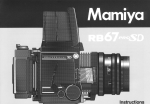
1
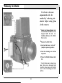
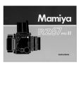
Building upon its long experience since the introduction in 1970 of the
revolutionary RB67 SLR with revolving back and the later refinements
incorporated into the RB67 Pro-S, Mamiya Camera Company has
utilized the latest electronic technology in order to fulfill its Commitment
to advanced amateurs and professional photographers by producing
the ultimate 6 x 7cm camera, the Mamiya RZ67.
The result is a camera with incredible versatility and handling ease.
ideally suited for commercial, industrial, scientific, news, portrait, scenic,
and fashion photography. In fact, the Mamiya RZ67 knows no bounds
in photographic application?.. However, in order to fully take advantage
of its capabilities, as well as avoid possible mishandling, be sure to carefully read this instruction manual before attempting to use your new
camera.
Contents
Special Features of the Mamiya RZ67 .................. .............................. ...
Outline of Names and Functions of Parts
s ..................................................
.
Inserting a Battery ...............................................................................
Attaching/Removing Lenses ......................................................................
Focusing Hood Operation .........................................................................
Releasing the Shutter .................................................................................
.....
Shutter Speed and Aperture ..............................................................
Focusing and Locking the Focusing Knob ...............................................
The Revolving Back ....................................................................... . . . .
. ...................
The Roll Film Holder ............................................................
Loading the Film Holder ......................................................... ........ .. ..
Taking Photographs ...................................................................................
Unloading the Film ......................................................................................
Distance Scale/Depth-of-Field ..................................... .............................
...............................
Close-up Photography ..............................................
Using a Tripod/Long Exposures...............................................................
Mirror-up Operation ....................................................................................
....................................
Multiple Exposures ..............................................
Flash Photography .....................................................................................
Close-up Photography with Auto Extension Tubes ...................................
How to Use fhe Carrying Strap ................................................................
Interchanging Magnifier/Focusing Hood/Focusing Screen ....................
Attaching a Lens with Shutter Released or Mirror Raised .........................
Camera Back Lock System ........................................................................
RB Series Lenses and Accessories ....................... ................................
Troubleshooting .........................................................................................
Care of the Camera ....................................................................................
Mamiya RZ67 Specifications ............................ ......................................
2
4
10
11
12
14
17
18
19
20
21
24
25
26
27
28
29
30
31
32
33
34
35
37
38
39
40
41
Special Features of the Mamiya RZ67
The following exemplify how the outstanding features of the
RB67 have been further refined in the Mamiya RZ67, resulting in unprecedented quality and performance.
The mirror-up mechanism is now automatically engaged as soon as a
cable release is attached to the Mirror-up Socket.
3. Improved Performance
1. Ultra Performance Lenses
Shutter speed accuracy and durability have been significantly enhanced by utilizing an electromagnetic release and Mamiya’s own Moving Coil system in conjunction with the Seiko #1 electronic shutter. Additionally, the longest fixed shutter speed has been increased to 8 seconds,
making the camera more flexible than ever.
When the camera is not prepared for use, the shutter release automatically locks and awaming lamp illuminates in the viewfinder, informing the
photographer precisely what needs to be done, a red lamp indicating that
the Dark Slide must be removed from the Film Holder, and an orange
lamp reminding the photographer to advance the Cocking Lever.
When using a Mamiyalite electronic flash, a green LED illuminates in
the viewfinder when the unit is fully charged and ready to fire.
For viewfinders with built-in exposure meters, the film speed, shutter
speed, and aperture information is electronically transmitted to the exposure meter.
With a Mamiyalite MZ36R or MZ18R attached to the RZ67, aperture
and film speed information is automatically and electronically_ relayed
_ to
the flash unit, controlling its light output. ’
By attaching Winder RZ and Receiver MZ to the RZ67, remote control
of the camera is possible with Transmitter MZ, thereby immensely increasing the applications of the camera.
Without changing the outer diameter of the lens mount on the camera
body, the inner diameter of the mount on the RZ67 has been increased by
7mm (from 54mm on the RB to 61mm on the RZ). Furthermore, the
flange back (distance of the lens mount to film plane) has been reduced
by the same amount (from 111 mm on the RB to 104mm on the RZ).
The increase in size of the diameter of the mount and decrease in the
distance of the flange back have made it possible to design a new series
of ultra performance lenses designed exclusively for the Mamiya RZ67,
offering performance previously believed unattainable. It is now also possible to design new, specialized optics, such as shift or high speed
lenses.
Moreover, any RB lenses already in the possession of the photographer can be used on the RZ67 without an adapter or loss in performance.
2. Improved Handling
It is now possible to advance the film and Exposure Counter, set the
mirrorand Light Baffle, and cock the lens with a single stroke of the Cocking Lever.
With Winder RZ attached to the camera body, a gentle touch of the
electromagnetic release makes it possible to effortlessly take consecutive photographs.
As the revolving back is rotated to change from horizontal to vertical format, or vice versa, the viewfinder masks also simultaneously change
automatically, preventing the photographer from seeing anything other
than the area actually being photographed.
While retaining the “T” (time) setting on the lens, a “B” (bulb) setting
has been incorporated into the Shutter Speed Dial of the camera body for
added versatility.
(Special Features Shared with the RB67)
The Ideal Format
The 6 x 7cm format not only offers an area approximately 4.5 x greater
than the 35mm negative size, but it enlarges to standard sizes, such as 8
x 1 0", with virtually no cropping, making it possible to utilize the full negative area. Ideally suited for publication and standard print sizes, the 6 x
7cm format makes the ideal choice for professional photographers.
2
Instant Change in Format
Lens Shutter Design
By revolving the back 90’, the photographer can instantly change from
horizontal to vertical format, or vice versa. In the RZ67. viewfinder masks
also change automatically, totally eliminating the chance of exposing the
film with the incorrect composition.
Use of a lens shutter makes it possible to synchronize electronic flash
at all shutter speeds, not only eliminating the problem of ghost images
(secondary images recorded by available light) occasionally encountered with focal plane shutters, but also enabling the photographer to
balance flash illumination with available light.
Peerless Film Flatness
After prolonged testing and research, Mamiya has developed Film
Holders which solve the problem of film curl by retaining the film perfectly
flat across the entire film plane. Thus, the full potential of Mamiya-Sekor
ultra performance lenses and the large negative size are realized.
In addition to unparalleled film flatness, the Roll Film Holders also incorporate a double exposure prevention mechanism. with multiple exposure provision as well.
Mirror-up Photography
Interchangeable Film Holders
Built-in Bellows
120, 220 and Polaroid holders are available which not only allow the
photographer to select a holder in accordance with the application, but
also make it possible to change film in mid-roll from color to black and
white, or color negative to color reversal.
Since the RB and RZ67 have a built-in bellows with a maximum extension of 46mm, close-up photography is possible without accessories,
Moreover. by adding an extension tube, a magnification ratio of greater
than 1 :11 (lifesize) is possible.
Viewing Ease
Additional Features
The standard Focusing Hood opens with a single touch. exposing a
large: bright image on the Focusing Screen. With another touch, the
Magnifier Instantly rises for critical focusing. The four sides of the Focusing Hood totally block the screen from extraneous light so that the image
always remains bright and clear, enabling the photographer to work
speedily and accurately. Both hood and screen are instantly interchangeable.
The Film Holder can not be removed from the camera back unless the
Dark Slide is first inserted into the holder, thereby protecting the film from
accidental exposure to light. Additionally, after the holder is removed, the
Dark Slide remains locked to the holder, again guarding the film from
light.
When using wide-angle lenses, the Focusing Knob of the camera can
be locked at the hyperfocal distance for focus-free photography. The
Focusing Knob Lock Lever also proves useful when engaged in close-up
photography, using telephoto lenses, or taking consecutive exposures of
a stationary subject.
Finally, multiple exposures become possible with a mere flickof the RM
Lever.
For occasions when the camera is mounted on a tripod, both the RB
and RZ67 allow the photographer to raise the mirror well before releasing
the shutter. Since "mirror shock” is thereby completely eliminated. razorsharp photographs are still possible when working at high magnifications
or long shutter speeds. This feature is especially useful for close-up work,
telephoto photography, and use of “slow” shutter speeds.
3
l
Outline of Names and Functions of Parts
(Detailed instructions follow.)
R-M Lever
For double exposure prevention and
normal operation. keep R-M Lever
aligned with central index mark.
R: The lever is set to this position
before revolving the back.
M: Set the lever to this position when
desiring to take multiple exposures.
The lever is also kept at this position
when releasing the shutter without
film in the camera.
Carrying Strap Lug
Focusing Hood Lock Button
To remove the hood, push in on both
(right and left) lock buttons and lift hood
off camera body.
Lens Alignment Dot
In a single operation this lever advances the films, cocks the shutter. and
sets the mirror. For proper operation.
be sure to push the lever completely
Mirror
Do not touch the mirror under any circumstances.
As a safety feature. the shutter can not
be released unless the Dark Slide is
first removed. Make it a habit to first remove the Dark Slide before attempting
Shutter Release Jack Cover
Sliding the cover upwards reveals electrical contacts (lack) for an auxiliary
shutter release.
to take a photograph.
Shutter Release Button
A single scale indicating distance in
meters and feet is used for all lenses.
Collar Stop Lever
Focal Length Scale
As a safely feature. the Release Button
Collar can not be rotated to the orange
dot position until the Collar Stop Lever
is first depressed.
Curved lines representing most focal
lengths appear on this scale. The point
at which the appropriate focal length
curve intersects the Distance Gradualion indicates the distance focused
upon by the lens.
Release Button Collar
For normal operation the white dot on the Release
Button Collar is kept aligned with the white dot on the
Collar Stop Lever. Aligning the white dot of the collar
with the red dot on the camera body Iocks the Shutter
Release Button. Aligning the collar with the orange dot
makes it possible to operate the shutter at approximately 1/400 sec. without batteries in the camera.
Focusing Knob
4
Magnifier Release
To raise the magnifier. push the Magnifier Release to the left.
Magnifier
Interchangeable with other magnifiers
in various diopter strengths.
CdS Prism Finder, for the finder
switches will not Operate without the
cover in place.
Focusing Hood Catch
Focusing Screen
Shutter Speed Dial
The visible field of the focusing screen
automatically changes from vertical to
horizontal format, or vice-versa, as the
revolving back is rotated. The screen itself is also interchangable.
Lock Release Button
Film Advance Knob
When the @ mark on the
Speed Dial is aligned with the index
mark on the camera body, the dial will
lock in place.To unlock it, rotate the dial
while pushing in on the Lock Release
Button.
Memo Clip
Holds the film box top, or memo, as a
film-type reminder.
/
Focusing Knob Lock Lever
L Dark Slide Slot
5
Film Advance Coupler
The central pin transmits a signal to the
film holder which disengages the film
advance-stop and activates the multiple exposure prevention mechanism.
The small circle appearing on the Revolving Ring should be aligned with
either the uppermost (“12 o’ clock”) or
right-hand side (“3 o’ clock”) index.
To avoid damaging the camera do not
“.::::B+
Camera Back Mount Pin
Battery Chamber Cover
The camera uses a 6 volt alkaline or
silver oxide battery.
The socket has standard U 1/4"
threads which can be removed, converting it to a 3/8" socket.
Winder Coupler Cover
6
Bayonet Ring
Flash Sync Terminal
The Bayonet Ring is a breech mount which secures the lens onto the camera body. As a safety
feature, the lens can not be removed from the
camera body unless the mirror is set (lowered),
thereby assisting the Light Baffle in shielding the
film from light.
(X-sync)
Depth-of-Field Scale
Lens Distance Scale Knob
Lens Distance Scale
Aperture Ring
Depth-of-Field Preview Lever
Time Exposure Lever
Shutter Lock Pin
When the lens is removed from the camera body.
the spring-loaded Shutter Lock Pin emerges.
locking the shutter and preventing accidental
shutter release. If desired. the shutter can be released by rotating the Shutter Cocking Pins
clockwise while depressing the Shutter Lock Pin.
Mirror-up Socket
Merely screwing a cable release into the Mirrorup Socket prepares the camera for mirror-up, or
vibration-free, photography. When this is done
and the Shutter Release Button is depressed. the
mirror and Light Baffle rise. After rising, and any
trace of vibration is eliminated, the shutter can be
released with the cable release.
Cocking Position Marks
Shutter Cocking Pins
When manually cocking the shutter, be sure to
rotate the Shutter Cocking Pins as far as they will
go (to the red dot).
7
Roll Film Holder RZ
When the Film Holder is removed from the camera back, the Dark Slide is
automatically locked in the holder, preventing accidental removal. Placing the
Film Holder onto the camera back automatically unlocks the Dark Slide, so that
it can easily be removed
Film Speed Dial (I-SO)
Back Cover Latch
Exposure Counter
After releasing the shutter, a red band appears next to the frame number in the Exposure Counter. Upon advancing the film, the
red band disappears, informing the photographer that tie film i s advanced and ready
to be exposed.
-.--2 Lock Release Lever
Spool Release Pins
Depress these pins to load or unload a film
spool.
Holder Lock Lever
Film Spool Stud
Should one inadvertently attempt to remove
the Film Holder without first inserting the
Dark Slide, the Holder Lock Lever will not
unlock, thereby preventing accidental exposure of the film to light.
A new roll of film is loaded on this stud with
the paper leader pulled over the roller in the
direction indicated by the dotted line and
arrow which appears around the stud.
Take-up Spool
Alter removing an exposed roll of film, place
the empty spool at this position.
the film holder is closed, and the film advanced until the numeral “1” appears in the
Exposer Counter.
8
Inserting a Battery
Even if battery power is depleted, aligning the Release Button Collar with the orange dot will make it
possible to release the shutter at approximately
1/400 sec.
l
Because the Mamiya RZ67 does not function properly without a battery, be sure to load
one into the Battery Chamber before attempting to use the camera.
The camera uses one of either of the following batteries:
4LR44
4 (6V alkaline manganese battery)
4SR44 (6V silver oxide battery)
1. Pull the Battery Chamber Cover in the direction of the arrowhead to open it.
2. Insert the battery into the chamber, taking
care to match the f poles of the battery with
those shown in the diagram found in the
chamber. Future replacement of the battery will
be simplified if the Battery Removal Ribbon (A)
is placed under and over the battery.
10
CAUTION:
1. Be sure to match the poles of the battery with those
shown in the diagram in the chamber.
2. Carefully wipe the contacts of the battery before inserting it into the chamber. Failure to do so could result
in poor electrical contact and consequent erratic functioning of the camera.
3. When not using the camera for a long period of
time, remove the battery and store it in a dry, cool
place.
4. Used batteries can be dangerous. Consequently,
when disposing of a battery. do not place it in a fire or
short circuit it.
5. Battery life varies considerably in accordance with
the following factors: battery, type, battery brand,
freshness of the battery when purchased, the conditions under which the battery was stored before
purchase and is stored after purchase, temperature at
the time of use, whether the battery receives frequent
or intermittent use.
6. Silver oxide batteries have longer battery life than
alkaline batteries.
Attaching/Removing Lenses
Attaching
Lenses
Before attaching a lens to the camera body,
the mirror of the body must be set and the shutter of the lens cocked.
(A) Setting the Mirror
1. Remove the Body Cap from the camera.
2. Make sure the mirror is set (lowered). If the
mirror is raised, lower it by pushing the Cocking
Lever as far as it will go toward the front of the
camera body.
(B) Cocking the Lens Shutter
(C) Attaching the Lens
1. Remove the Rear Lens Cap.
2. If the lens shutter is not cocked, firmly rotate
the Shutter Cocking Pins as far as they will go
(to the red dot). When releasing the pins, they
will return to the green dot and the shutter
blades will remain open.
1. With the front of the lens facing you, rotate
the Bayonet Ring counterclockwise as far as it
will go (the white dot on the Bayonet Ring will
be aligned with the central index of the lens).
2. Seat the lens on the camera body with the
central index of the lens lined up with the red
Alignment Dot of the camera body. Next, rotate
the Bayonet Ring of the lens firmly in a
clockwise direction, securing the lens to the
camera body.
l Moving the Shutter Cocking Pins only as far as the
green dot will result in incomplete shutter cocking.
Be sure to rotate them as far as the red dot.
l Whenever a lens i s removed from the camera body
it is already Cocked.
11
Focusing Hood Operation
Removing Lenses
Raising the Focusing Hood
1. Push the Cocking Lever of the camera body
completely down, setting the mirror and cocking the lens shutter.
2. Rotate the Bayonet Ring of the lens counterclockwise as far as it will go (white dot of
Bayonet Ring will align with central index of
lens) and remove lens.
l If you try to rotate the Bayonet Ring counterclockwise without first depressing the Cocking Lever of the camera body, the movement of
the ring will be interrupted, making it impossible
to remove the lens. This safety feature assures
that the mirror is always lowered whenever the
lens is removed, thereby assisting the Light
Baffle in shielding the film from light.
Merely lift the back of the hood until it opens
completely.
12
Raising the Magnifier
Lowering the Magnifier
. r
Folding the Focusing Hood
Slide the Magnifier Release slightly to the left
and the Magnifier will pop up into position.
Gently push the base plate of the Magnifier
all the way down until it locks in place.
Afler lowering the Magnifier, gently squeeze
the right and left panels of the hood together
while closing it.
13
r
Releasing the Shutter
It is best to become
acquainted with the
method of releasing the
shutter before using film
in the camera.
1. Rotate the Release Button Collar until the white dot on it is
aligned with the one immediately below (on the Collar
Stop Lever).
2. Remove the Dark Slide.
3. Set the R-M Lever to the “M”
(multiple exposure) position.
4. Push the Cocking Lever all the
way down.
5. Press the Shutter Release Button.
The first 4 steps can be done in any
order. After you are thoroughly familiar with the above steps, return the RM
Lever to its normal setting (the center
position).
/
\
14
Using the Release Button Collar I
1. For normal operation, align the white dot on
the Release Button Collar (A) with the white dot
on the lever below (B). When this is done, the
Shutter Release functions electromagnetically
and the various safety mechanisms operate
electrically.
The Normal Position
For normal operation of the camera, the R-M
Lever should be kept in the center position,
aligned with the index mark. Setting the lever to
this position activates the double exposure prevention mechanism so that photo after photo can
be taken without fear of accidental double exposures.
2. When the camera is not in use, lock the Shutter Release Button. This is done by aligning the
white dot of the Release Button Collar with the
red dot (C) on the camera body. By locking the
Shutter Release Button, you not only prevent unintentional exposure of film, but also prevent accidental battery drainage caused by pressure on
the Release Button. For this reason, be sure to
lock the Release Button when carrying the camera in a bag.
Multiple Exposure Position
When desiring to make deliberate double of
multiple exposures, set the R-M Lever to the "M"
position. When this is done, pushing down on the
Cocking Lever will cock the lens shutter, but will
not advance the film. Upon completion of the
multiple exposure, do not forget lo return the R-M
Lever to its normal (center) position. The lever is
also set to ‘M’ when testing the shutter without
film in the camera.
Emergency Shutter Operation
If you were to suddenly find yourself with a
dead battery in the midst of a photographic session, switch over to the emergency Shutter operation mode. In order to do so, push the Collar
Stop Lever (D) toward the camera body and
while holding it there align the white dot of the Release Button Collar with the orange dot (E) on the
camera body. The shutter will now operate (even
without a battery) at approximately 1/400 sec.,
regardless of the setting of the Shutter Speed
Dial.
Because electricity is not being used in the
emergency shutter operation mode, the Monitor
Lamps in the viewfinder will not illuminate.
Moreover, even if the Dark Slide is not withdrawn, the shutter can still be released, so exercise care.
l
Revolving Back Position
Before revolving the back, set the R-M Lever to
the "R
"R" position. After this is done, the lever will
automatically return to the normal position when
the Shutter Release Button or Cocking Lever is
next used.
15
I
[ Operating the Cocking Lever /
Under the following circumstances an orange, red, or green lamp will illuminate in the viewfinder when the Shutter Release Button is depressed.
1. Cocking Lever Not Set (Orange warning lamp)
If the Cocking Lever has not been depressed or has been only partially
depressed, an orange warning lamp will illuminate in the viewfinder when
the Shutter Release Button is pressed, warning the user that the film has
not been advanced, the mirror not been set, and the shutter not been
cocked.
2. Dark Slide in Holder (Red warning lamp)
When attempting to take a photograph without removing the Dark Slide
from the Film Holder, the Shutter Release Button will lock and a red warning lamp acts as a reminder to withdraw the Dark Slide.
When depressing the Cocking Lever, be sure to push it all the way forward (toward the Shutter Release Button).
If the Cocking Lever is not pressed forward as far as it will go, It will return to its original position when released, but the shutter will not be
cocked. At such a time, the shutter will not operate and an orange warning lamp will illuminate in the viewfinder when the Shutter Release Button
is depressed.
Depressing the Cocking Lever advances the film, sets the Light Baffle
and mirror, and cocks the shutter.
3. Mamiyalite Charged (Green signal lamp)
When a Mamiyalite ZE, MZ 18 R, or MZ 36 R is connected to the HotShoe and fully charged, a green lamp will illuminate upon pressing the
Shutter Release Button halfway, indicating that the flash unit is ready to
fire.
4. Battery Check
To check the condition of the battery, insert the Dark Slide into the Film
Holder and depress the Shutter Release Button; the red warning lamp
should illuminate with a steady glow. If the red lamp flickers, it indicates
that battery voltage is low and the battey should be replaced as soon as
possible.
16
,
Shutter Speed and Aperture
The Shutter Speed Dial
The Aperture Ring
When the Shutter Speed Dial is set to “B”
(bulb). the shutter will remain open as long as
pressure is applied to the Shutter Release Button and will close as soon as pressure is released.
The 0 mark which appears between “B”
and 400 on the Shutter Speed Dial is the setting
for the AE Finder (which will be available in the
future). When set at this position. the dial locks
in place. To unlock it, rotate the dial while depressing the Lock Release Button which appears in the center of the dial.
I
Select the shutter speed desired and rotate
the Shutter Speed Dial until the appropriate figure is aligned with the shutter speed index
mark.
The Shutter Speed Dial must be set to a
click-stop position and can not be used at in-between settings.
The numerals as they appear on the dial and
the shutter speeds they represent are shown in
the following table.
Numerals
Shutter peed
To set the diaphragm to a desired aperture,
rotate the Aperture Ring until the appropriate figure is aligned with the central index line. It is
perfectly acceptable to use the Aperture Ring at
in-between click-stop settings.
When the Shutter Release Button is depressed, the diaphragm will automatically stop
down to the preselected aperture before the
shuner opens for the exposure.
Fractions of a second
Wholeseconds
400 250 125 60 30 15 8 4 2
1 2 4 8
1/400 1/250 1/125 1/60 1/30 1/15 1/8 1/4 1/2
1 2 4 8
17
Focusing and Locking the Focusing Knob
Focusing
Locking the Focusing Knob
Depressing the Cocking Lever sets the mirror. projecting a bright image on the focusing
screen. Focus by rotating to-and-fro either of
the two Focusing Knobs until the image appears sharp.
After adjusting the focus, focusing deviation
can be prevented by locking the Focusing Knob
with the Focusing Knob Lock Lever, which is
found at the rear of the left-hand Focusing
Knob. Simply raise the lever and push it forward. clamping the Focusing Knob in place.
When working with wide-angle lenses, the
lens can be prefocused at the hyperfocal distance, and the knob locked with the Focusing
Knob Lock Lever so that snap-shots can freely
be taken without the need of focusing. Examples of other occasions on which the lock lever
will prove useful include when copying, engaging in macrophotography, or using telephoto
lenses.
18
The Revolving Back
The Vertical and Horizontal Formats
Change in Viewfinder Format
Before attempting to revolve the back, set
the R-M Lever to “R” To change from horizontal to vertical format, rotate the Film Holder
clockwise as far as it will go. Rotating it counterclockwise, changes the format from vertical
back to horizontal.
Be sure to rotate the Film Holder gently, as undue
use of force can result in damage to the camera.
The R-M Lever will automatically return from “R” to
its normal position upon depressing the Cocking
Lever or Shutter Release Button. However, as long as
the R-M Lever remains at the “R” setting, the Film Holder can inadvertently be moved of-center. Consequently, we recommend manually returning the
lever to its normal position (center index mark) immediately after revolving the back.
I
As the revolving back is rotated. the viewfinder format automatically changes
from horizontal to vertical, or vice versa. This is accomplished by viewfinder
masks which are coupled to the revolving back.
Additionally, when viewed from the top, a small rectangle appears at the upper
edge of the Film Holder. Visible at a glance, this rectangle acts as a reminder, indicating whether the holder has been set for the vertical or horizontal format.
19
The Roll Film Holder
Attaching the Holder
Remove the rear body cap by sliding it upwards.
CAUTION: Do not touch the Light Baffle or mirror.
Touching the Baffle could result in a light leak
or malfunction.
1. Slide the Holder Lock Lever of the Film Holder completely toward the Lock Release Lever
(A).
2. Align the orange circle (B) of the Revolving
Ring (found at the rear of the camera) with one
of the two white index marks on the camera
body.
Hold the Film Holder so that its orange circle
is at the same position as the one on the Revolving Ring (B) and fit the holder onto the camera back, taking care that the four Camera
Back Mount Pins fit into the four openings of the
holder
20
3. Lock the holder on the camera body by
moving the Slide Lock as far as it will go in the
direction of the arrow.
Loading the Film Holder
Removing the Holder
4. Insert the Dark Slide into the Roll Film Holder. For instant recognition, the Dark Slide Slot
is bordered by white reference lines.
The Film Holder can be removed after moving the Holder Lock Lever as far as it will go toward the Lock Release Lever (A). It is recommended that you remove the holder on a table
or similar support, or in your lap, to avoid the
possibility of dropping the holder or having it fall
off the camera.
If you attempt to remove the holder without replacing the Dark Slide, the Holder Lock Lever will automattically lock in place. preventing accidental removal of
the holder and exposure of the film.
However, if you must remove the holder without the
Dark Slide in place. the automatic lock can be overrid
den by pulling the Lock Release Lever toward the Holder Lock Lever, holding the lever there, and then moving the Lock Lever.
1. Pull out the upper and lower Back Cover
Latches and the back cover will open.
Because of the double safety lock, pulling out
just one of the two Back Cover Latches will not
open the back cover.
After opening the back cover of the Roll Film Holder,
remove the Film Insert. When loading film, it is not
necessary to remove the holder from the camera
back.
When loading film, avoid direct sunlight, either load-
ing the film in the shade or turning your body away
from the sun and loading it in the shade of your own
body.
21
2. While holding down the left-hand Spool Release Pin of the Film Insert, fit a roll of film between the upper and lower left-hand Film Spool
Studs.
Pull the backing paper in the direction of the
dotted line and arrow around the stud, over the
roller, across the back, over the right-hand roller, and feed it into the Take-up Spool. When
loaded correctly, the inside of the backing
paper (black side) w i l l appear outside of the insert back. If it does not, remove the roll of film,
turn it upside-down, and reload it.
Loading the Film Holder
3. After feeding the tip of the backing paper
into the slot of the Take-up Spool.
4. Gently wind the Film Advance Knob until the
arrow of the backing paper aligns with the insert
Start Mark.
As you gently advance the backing paper, make
sure it advances evenly between the spool flanges
and does not begin to slant. If it advances unevenly,
remove the backing paper from the Take-up Spool
and refeed, starting again. Heeding this point will
eliminate the possibility of crinkling the edge of the
film.
22
5. Set the correct film speed value on the Film
Speed Dial of the Roll Film Holder.
Advancing the Film
6. Place the Film Insert into the outer cassette,
making sure the film advance coupler of the insert fits into the appropriate opening of the cassette.
7. After correctly placing the insert into the cassette, close the back cover, and while gently
holding it in place, push both of the Back Cover
Latches as far as they will go.
The RZ Roll Film Holder outer cassette will accept
either 120 or 220 Film Inserts .
23
Before attempting to advance the film to the
first frame, make sure the R-M Lever is set to its
normal (center) position. If the lever is set to ‘M
(multiple exposure), it will not be possible to advance the film with the Cocking Lever.
Taking Photographs
When the film is advanced to the next frame,
the numeral in the Exposure Counter will automatically change and the red mark will disappear.
Operate the Cocking Lever gently. If if is
pressed very rapidly, the spacing between
frames may not be uniform.
After an exposure is made, the automatic double exposure prevention mechanism will make
it impossible to release the shutter until the film
is advanced.
After completing the last exposure, press the
Cocking Lever several times, until the film and
backing paper is completely wound onto the
Take-up Spool. Instead of using the Cocking
Lever, you can use the Film Advance Knob of
the Film Insert, if you prefer.
The film can be advanced in either of two
ways.
A) By winding the Film Advance Knob of the
Film Insert until it stops.
B) By pressing the Cocking Lever of the camera body several times, until it stops. (The lens
shutter will not be cocked unless the Cocking
Lever is consecutively pressed until it stops.)
When the film is completely advanced, the
numeral ‘1’ will appear in the Exposure Counter
and the red, film-unadvanced warning will disappear.
While advancing the film from S (start) to 1
with the Cocking Lever, the shutter releasing
mechanism is automatically locked until the film
is fully advanced to frame 1.
After removing the Dark Slide and releasing
the shutter, the red warning mark will reappear
in the Exposure Counter, indicating that the exposure has been made and the camera needs
to be set for the next exposure.
24
Unloading the Film
When desiring to turn in for processing a roll
of film that has been only partially exposed, first
remove the holder after inserting the Dark
Slide. Next, while holding in the pin in thecenter
of the coupler(A), completely wind the film onto
the Take-up Spool with the Film Advance
Knob. Instead of continuously holding in the
coupler pin, you can push it in once after each
frame, if preferred.
During exposures, the Dark Slide can be
stored in the Dark Slide Slot in the back of the
holder.
The Memo Clip on the back cover can be
used for holding the film box-top as a film reminder or for holding a piece of paper with special
1. Open the back cover of the Film Holder and
remove the Film Insert.
2. While holding down the right-hand Spool
Release Pin, remove the film, exercising care
that the backing paper does not unroll or become loose.
3. In preparation for the future, remove the
empty spool from the Film Insert, replacing it on
the right-hand side so that it will act as the new
Take-up Spool.
When the back cover of the holder is opened,
the Exposure Counter will automatically return
to "S" (Start).
If anything other than ‘s’ appears in the Exposure
Counter, it indicates that there is film in the holder. To
prevent accidental exposure of the film to light, always
check the Exposure Counter before opening the back
cover of the holder.
25
Distance Scale
The Distance Scale is used to determine the
film-plane-to-subject distance. The scale itself
is composed of two parts, the Distance Graduation and Focal Length Scale.
After focusing, the correct distance can be
determined by locating the point at which the
curved line for the focal length in use intersects
the Distance Graduation.
For example, tithe 110mm lens is mounted
on the camera and focused as shown in the illustration, the subject is 1.5m (5 ft) from the film
plane.
Depth-of-Field
Depth-of-Field Preview
Using the Depth-of-Field Scale
1. Set the Aperture Ring to the desired f-stop
and focus the lens.
2. Depress the Depth-of-Field Preview Lever
of the lens and you will be able to check the
depth-of-field directly on the focusing screen.
1. Check the camera-to-subject distance on
the Distance Scale.
2. Rotate the Lens Distance Scale Knob until
the previously noted camera-to-subject distance is aligned with the center index of the
Depth-of-Field Scale.
3. Locate the selected aperture on both sides
of the Depth-of-Field Scale.
4. The figures of the Lens Distance Scale, appearing above the selected aperture, indicate
the nearest and furthermost limits of sharpness
for that aperture.
For example, when the 110 mm lens is focused at 3m and stopped down to f/32, everything from approximately 2m to 10m will be in
focus.
When desiring to know the depth-of-field in
feet, rotate the Lens Distance Scale 180”,as
one side is in feet and the other in meters.
26
Close-up Photography
Exposure Compensation for Close-up Photography
When working very close to the subject, the
exposure must be increased. The actual exposure factor will vary in accordance with the distance that the lens is extended. This is simply
because the brightness of the image striking
the film grows increasingly dimmer as the lens
is progressively moved further from the film
plane.
Exposure compensation is easily determined by referring to the Exposure Compensation Scale.
1. After focusing the lens, read the exposure
compensation factor on the scale. The scale is
divided into three zones of light, medium, and
dark shades. As indicated by the table at the
base of the scale, the light zone represents an
exposure factor of zero (no compensation is
necessary), the medium shaded zone indicates +0.5 (a 1/2 stop increase in exposure is
required), and the dark zone denotes a factor of
Area Covered with Bellows fully Extended
+ 1 (a full stop increase in exposure is necessary).
To find the exposure factor, first locate the figure on the Focal Length Scale for the lens in
use. Next, move along the scale, in the same
column, until you reach the Distance Graduation. The shading of the zone (light, medium,
dark) which touches the Distance Graduation
indicates the correct exposure factor. For
example, when the 110mm lens is focused as
shown in the illustration, the correct exposure
factor is + 1.
2. Compensate the exposure by changing
either the shutter speed or aperture. When the
exposure factor is +1, either open the aperture
or lengthen the shutter speed by a full stop.
With a factor of +0.5, open the aperture by a
half-stop. For example, assume that a handheld exposure meter indicates a normal exposure reading of f/16 at 1/60 sec., for exposure
27
compensation of + 1, set the lens to either f/16
at 1/30 sec. or f/11 at 1/60 sec.
When using a finder with a built-in meter,
such as the PD Prism Finder, there is no need
to compensate for close-up photography.
l For optimum clarity at the corners when using the
50mm and 65mm wide-angle lenses at distances
closer than 1 meter, use as small an aperture as pos-
sible.
l The bellows extension in millimeters appears on
the top of the Focal Length Scale. These figures are
used to determine the required exposure compensation factor when using extension tubes.
Using a Tripod
Long Exposures
Bulb (B) Exposures
For optimum quality, use of a large, sturdy
tripod is recommended.
1. The Tripod Socket will accept standard size
(U 1/4" thread) tripod screws without modificalion. Simply attach the RZ 67 as you would any
other camera with standard threads.
2. When using a tripod with a 3/8” screw, first
remove the small screw in the base of the
Tripod Socket of the camera by rotating it counterclockwise with an appropriate screwdriver.
Next, use a coin to remove the 1/4” adapter (A)
from the Tripod Socket by rotating it counterclockwise. The camera can then be mounted
on a 3/8" screw tripod.
When the Shutter Speed Dial is set to B, the
shutter will remain open as long as the Shutter
Release Button remains depressed. Since bulb
exposure is also controlled electronically, the
shutter will automatically close after approximately one minute in order to prevent inadvertent battery depletion. When using bulb, if the
Shutter Release Button is depressed for approximately 50 seconds, a warning buzzer will
sound. If pressure on the Release Button is
maintained, the buzzer will continue for about
10 seconds longer, after which the electricity
will be automatically extinguished and the shutter will close. When desiring to take exposures
of longer than one minute, use time exposures.
28
When using bulb, if pressure is released from the
Shutter Release Button too quickly (before the mirror
completes its upward travel), the shutter may remain
open. To correct this situation, press the Shutter Release Button once again, upon releasing pressure the
shutter will close. If you do not correct the situation
yourself. the buzzer will sound after approximately 50
seconds, 10 seconds the buzzer will stop and the
shutter close.
Mirror-up Operation
Time Exposures
1. To make a time exposure, first slide the T
Lever of the lens until the letter "T" is exposed.
After doing so, the shutter will remain open
upon depressing the Shutter Release Button.
At this time, the setting of the Shutter Speed
Dial on the camera body is inconsequential.
2. To close the shutter, slide the T Lever in the
opposite direction, exposing the letter ‘N’ (normal). During time exposures, do not touch the
Cocking Lever until the shutter closes.
Since the shutter operates mechanically, not
electronically, during a time exposure, there is
virtually no expenditure of battery power, and
the length of time the shutter remains open is
insignificant.
With the RZ 67, it is possible to lock the mirror
in the up position beforehand, and at the desired instant release the shutter without the
usual accompanying mirror movement.
Referred to as, “mirror-up operation,” this
technique is extremely valuable when desiring
to eliminate even the slightest mirror shock. Because the mirror normally rises and causes vibrations the very instant before the shutter
opens, a loss of sharpness is possible when
working at high magnifications or with long
shutter speeds. Consequently, mirror-up operation is especially useful when engaging in
close-up photography, using telephoto lenses,
and making long (“slow") exposures. Yet
another application is when trying to catch the
peak of action. By raising the mirror beforehand, the shutter can instantly be released,
totally eliminating the time lag usually present
between the time the mirror completes its upward swing and the time the shutter opens.
29
1. After screwing a cable release firmly into
the Mirror-up Socket of the lens, the socket will
elevate slightly and the camera will be ready for
mirror-up operation.
2. Press the Cocking Lever as far as it will go.
Step 2 may either follow or precede step 1.
3. Depress the Shutter Release Button. The
mirror will rise, but the shutter will remain
closed.
4. Press the plunger of the cable release and
the shutter will operate.
5. When you no longer need mirror-up operation, remove the cable release.
Upon removing the cable release, the ,Mirror-up Socket will retract and the camera will
return to normal shutter operation.
Multiple Exposures
If you complete step 3 above, but remove the cable release without making an exposure (step 4), the shutter
will be released as soon as the cable release is removed.
Even when using mirror-up operation, everytime
the shutter is cocked, the mirror is relowered. Therefore, it is possible to check the viewfinder before each
frame is exposed.
A convenient double cable release is available as
an accesory. Since one end of the release screws into
the Shutter Release Button and the other end into the
Mirro-up Socket, if is possible to use the same release
to raise the mirror and later release the shutter.
. If you release the shutter with the cable release after
the buzzer stops, the shutter speed will be 1/400 sec.
If you wish to use a shutter speed other than 1/400
sec. after the buzzer stops, follow the procedure for
multiple exposure.
Using Bulb with Mirror-up Operation
1. Attach cable release to Mirror-up Socket.
2. Set the Shutter Speed Dial to B
3. Press the Shutter Release Button (mirror rises).
4. Press plunger of cable release (shutter opens).
5. Press Shutter Release Button (shutter closes).
CAUTION
l As long as a cable release remains attached to the
Mirror-up Socket, it is possible to use the same release to raise the mirror and later release the shutter.
Photograph by merely pressing the Shutter Release
Button.
l lf the red line around the Mirror-up Socket is still visible when the cable release i s removed, the camera is
still set for mirror-up operation. If such is the case,
reattach the cable release, making sure that the socket retracts as you remove it once again.
. The shutter should be released with the cable release within 50 seconds of pressing the Shutter Release Button. If this is not done, the buzzer will sound
after 50 seconds and continue for 10 seconds before
stopping.
1. Set the R-M Lever to ‘M’ (multiple exposure). The lever can be moved to ‘M’ either before or after releasing the shutter.
2. Press the Cocking Lever as far as it will go
in order to cock the shutter and set the mirror.
The film will not move at this time. The shutter
can now be released, creating a double exposure. This procedure can be repeated as often
as desired.
When photographing the same subject 2 or more
times exposure compensation is necessary. The
same is true with different subjects that are all evenly
illuminated. With subjects of different brightness, the
darker one is normally photographed first. However, it
is not within the scope of this operating manual to
teach multiple exposure technique, as many excellent
books dealing with this subject are already available.
After completing your multiple exposure, immediately replace the R-M Lever to its normal postion. If this is not done, the shutter may later be released mistakenly, not only ruining the multlple exposure, but also ruining the additional exposure.
30
Flash Photography
Attaching Flash Units
Compact, clip-on units can be attached directly to the Hot-Shoe of the camera.
When using large, grip-type units, attach the
sync cord to the flash to the Flash Sync Terminal (X-sync) of the lens.
When using the Mamiyalite ZE, MZ 18 R, or
MZ 36 R, and pressing the Shutter Release
Button halfway, the green monitor lamp in the
viewfinder will illuminate if the flash is fully
charged and ready to fire. When using Mamiya
flash units, two units can be fired simultaneously by connecting one unit to the Hot-Shoe
and the other to the Sync Terminal.
However, if the same procedure were followed with flash units of other makes, damage
may result to the camera or flash units. Therefore, if using flash units of other makes, be sure
to use only one at time (unless others are fired
by slave units).
Determining the Aperture
When using automatic flash units, refer to the
instructions of the flash unit for the correct apertures to use.
When using a manual electronic flash unit or
flash bulbs, the guide number divided by the
subject distance gives the correct aperture to
use.
G.N. (48)
= Correct aperture
setting (8)
Subject Distance (6)
Flash Synchronization Table
Flash Type
Electronic _
M-class bulb
Shutter Speed
1/60-1/400
8 sec.-1/30
Yes
Yes
No
Yes
31
-
Close-up Photography with Auto Extension Tubes
After attaching an auto extension tube to a
lens, treat the extension tube/lens combination
as a single unit, attaching and removing them
from the camera as any other lens. Moreover,
when using the auto extension tubes, diaphragm automation of the lens is fully maintained sot hat close-up photography is as convenient as standard operating procedure.
CAUTION
1. Because of the extraordinarily shallow depth-offield encountered in close-up photography, use as
small an aperture as possible.
2. Mirror-up operation is recommended for optimum
results.
3. When using a finder with built-in exposure meter,
exposure compensation is not necessary. However,
when working with a handheld meter, compensation
is required. Refer to the individual instructions that
come with the auto extension tubes.
Close-up Table
.I
Extension Tubs
Magnification
Subject
Distance (cm)
Area Covered (cm)
(ll.Zx13.9)-i5.5x6.9)
(6.1X7.6)-(3.9X4.9)
nmt12.8
’
/
nmfB.8
j
I
x0.1 +No.Z
1.41-1.92
8.5- 6 . 8
No. 1
0.41-0.82
31.9-18.1
Na2
0.74-1.15
19.6-14.2
Na 1 +No.2
1.15_~1.56
14.3Pl1.7
(4.0X4.9)-_!2.9X3.6)
~13.8x17.1~-!6.8x6.5~
(7.6X9.4)-(4.8X6.0)
(4.9X6.1)-(3.6X4.5)
No. 1
0.35-0.72
44.9-26.8
(15.6X19.6)-(7.8X9.7)
Na2
0.65-1.01
28.7-21.7
(8.7X10.8)-(5.6X6.9)
l.OO~-1.36
21.8-18.4
(5.6X7.0)-(4.1X5.1)
NnlfNo.2
32
l The subject distance appearing on the
Close-up Table refer to the distance from the
front rim of the lens to the subject.
l The two rows of figures appearing in the
“Magnification,” “Subject Distance,” and “Area
Covered” columns of the table apply to zero
and maximum (46mm) extension of the bellows. Figures to the left indicate no extension,
figures to the right, maximum extension.
How to Use the Carrying Strap
Attaching the Strap
Three Carrying Positions
Hold the metal clamp of the strap
so that the key-hole shaped opening faces the Carrying Strap Lug on
the camera body. Gently fit the
upper part of the key-hole opening
over the lug. Next, gently push the
bottom of the metal clamp upwards
and it will lock in place with a click.
Depending upon the way the
strap is attached to the camera.
there are three ways of carrying the
camera as shown in the accompanying illustrations. Since the Carrying Strap Lug is not rotary, the carrying strap will not become twisted.
If the clamp is attached to the HotShoe side of the camera upsidedown, it will be difficult to remove, so
be careful to attach the clamp rightside-up.
Removing the Strap
Reach behind the strap and while
gently squeezing the top of the protruding front plate (leaf spring), slide
the clamp downward and off the lug.
33
Interchanging Magnifier/ Focusing Hood/Focusing Screen
Magnifier
Focusing Hood
Focusing Screens
The Magnifier of the Focusing Hood is interchangeable. In addition to the standard (- 1.3
diopter) magnifier, the following diopter lenses
are also available: +1, 0, -1, -2, -3.
To remove the Magnifier, gently squeeze the
sides of the Focusing Hood, preventing the
Magnifier Base Plate from moving, rotate the
Magnifier counter-clockwise and remove.
Removing the Focusing Hood
There are seven instantly interchangeable
focusing screens to choose from, each designed for specific applications.
To remove the Focusing Hood, merely
squeeze both Focusing Hood Lock Buttons toward each other and lift the hood off the camera.
Attaching the Hood
To attach the hood, slide the Focusing Hood
Catches into the groove of the camera body,
and while holding in both Focusing Hood Lock
Buttons, seat the front of the hood on the camera body. The hood will lock in place after releasing pressure from the Lock Buttons.
34
Removing a Focusing Screen
After removing the focusing hood, lift up and
remove the screen by grasping the lug on the
right-hand side (as viewed from the back of the
camera). To replace a screen, gently lower the
left-hand side of the screen (as seen from the
camera back), followed by the right-hand side,
and lightly snap screen into place.
CAUTION
When removing screens, exercise care not to touch
the vertical and horizontal format viewfinder mask.
Attaching a Lens with Shutter Released or Mirror Raised
When a lens is removed from the camera
body, the mirror is set (lowered) and the lens
shutter cocked. Conversely, when attaching a
lens, the same conditions should prevail (mirror
set and shutter cocked). However, should a
lens be attached with either the mirror raised or
shutter released, or both, the camera can be
reset by following the procedures below.
Mirror condition
1. If the mirror is raised (regardless of whether
the lens shutter is cocked or released), simply
depress the Cocking Lever to reset the camera.
2. If mirror is set and lens shutter released
(closed), remove the Dark Slide from Film
Holder and depress the Shutter Release Button (film will not be exposed). Next, depress the
Cocking Lever to reset the camera.
Shutter blade condition
Overriding the Dark Slide Safety
Overriding the Shutter Lock Pin
When a Film Holder is removed from the
camera body, the Dark Slide automatically
locks in place to prevent possible exposure of
the film to light. Nevertheless, this safety lock
can be overriden if necessary. Simply depress
the Dark Slide Release Pin (A) with the tip of a
ball point pen or similar object and remove the
slide.
If a lens. is not to be used over a prolonged
period, it is desirable to store it with the shutter
released. In order to release the shutter of a
lens which has been removed from the camera
body, rotate the Shutter Cocking Pins (C)
clockwise while depressing the Shutter Lock
Pin(B).
36
Camera Back Lock System
120 Roll film holder RZ
220 Roll film holder RZ
Roll film holder for Mamiya RB
(and G-lock system holders)
Polaroid Land pack film holder RZ
The unique camera back lock system of the
Mamiya RZ67 is designed to allow it to accept a
large variety of Film Holders. All RZ series Film
Holders mount and lock directly on the back of
the RZ67.
i
j
G adapter RZ
/
I
All RB67 series holders (G-Lock System)
can be attached to the RZ67 via the G Adapter
RZ.
37
RB Series Lenses and Accessories
l
1.
Lenses
Focusing
l
Film Holders
Follow the procedure outlined below in order to use RB series (G-Lock
System) holders on the RZ67.
RB67 lenses mount directly onto the RZ67; however, the bellows must
be extended 7mm in order to focus the lens at infinity (m).
Therefore,
even when photographing distant subjects, be sure to use the Focusing
Screen.
1. Attach G Adapter RZ to the back of the RZ67.
2. Set the R-M Lever of the camera body to “M”. If the lever is set to its
normal position (the central index mark), the shutter will not release.
CAUTION: Because of the differences in flange back between the two
series of lenses, the Distance Scale of the RZ67 body does not apply
when using RB67 lenses.
3. Advance the film with the Film Advance Lever of the Film Holder.
4. After releasing the shutter, slide the Film Wind-Stop Release Lever of
the holder to the left, freeing the film, and advance the film to the next
frame.
2. Shutter Speed Selection
When a R B 6 7 lens is mounted on the RZ67 body, use the Shutter
Speed Ring of the lens for shutter speed selection. The setting of the
camera body Shutter Speed Dial is inconsequential.
The shutter is cocked and released in the same manner as RZ series
lenses.
CAUTION:
* The Film-Unadvanced Indicator (red bar appearing in the Exposure
Counter window) comes into view after the Film Wind-Stop Release
Lever is moved.
* The double exposure prevention mechanism does not operate when
a Pro-S Roll Film Holder is used on the RZ67 body, so do not forget to advance the film immediately after releasing the shutter.
l Even if a Dark Slide is not inserted into a Pro-S Roll Film Holder, it can
still be removed from an RZ67 camera body. Therefore, when desiring to
remove a holder containing a partially exposed roll of film, be sure to first
insert the Dark Slide.
* The Shutter Release Button of the RZ67 will not lock automatically,
nor will the viewfinder red warning lamp illuminate if a Dark Slide remains
in a Pro-S Roll Film Holder. Consequently, be sure to remove the Dark
Slide before beginning a picture-taking session.
38
Troubleshooting
NXK3 Finders
When using the RB series CdS Finder or CdS Prim Finder on a RZ67
body, be sure the Electrical Contact Cover is in place, for it is used to depress the switch at the base of the finder.
The Lens Speed Scale of either of the above finders does not have provision for a lens faster than f/3.8; therefore, when using the MamiyaSekor Z 110mm f/2.8 lens, follow the procedure indicated below.
Uniquely designed to prevent errors, the RZ67 incorporates
numerous safety features, so if you can not release the shutter,
or remove a lens or holder, it is most likely due to user error rather
than a camera malfunction. Should something appear to go
wrong, be sure to check the following points.
1. Set the Lens Speed Scale to 3.5.
2. Next, set the Film Speed Dial of the finder to 1/2 the actual film speed.
For example, when using 100 ASA (ISO) film, set the dial to 50.
When the shutter can not be released
1. Has the film been completely advanced to the first frame?
Have all the exposures already been made (10 with 120, 20 with
220)?
2. Has the Cocking Lever been advanced as far as it will go?
3. Has the Dark Slide been removed?
4. Have you locked the Shutter Release Button and forgotten?
5. Is there a battery in the Battery Chamber’? Is the battery still
good?
l In the case of examples 1-3, an orange lamp will illuminate in
the viewfinder if an error has been made.
When the lens can not be removed
Have you pressed the Cocking Lever completely forward?
When the Film Holder can not be removed
Have you inserted the Dark Slide into the holder?
39
Care of the Camera
When not used for a long period of time, remove the battery and any
film from the camera. Do not store the camera at temperatures exceeding
40°C or below -10°C. Also avoid storing the camera in a damp or salty
area.
As your camera is a precision instrument, avoid exposing it to severe
vibrations or shocks. When handholding your camera always use a neck
strap and exercise extreme caution when removing a lens or Film Holder.
Prolonged disuse does not lengthen camera life, but shortens it. Thus,
when storing a camera for a long time, periodically remove the camera
and release the shutter several times to keep the camera in good condition.
Cleaning
Do not touch the lens or mirror surfaces. If a lens needs cleaning, use a
blower or lens tissue to remove dust particles. Never use anything other
than a blower for the mirror, as its surface should never be touched.
Periodic Check
Periodically check the camera to make sure it is in working order. This
is especially important before beginning a photographic session or assignment. Check the battery, flash synchronization, mirror and shutter
operation, diaphragm automation, and film advance. Also check any accessories you plan to use.
For a general overhaul, cleaning, or minor repair, take the camera to
your nearest authorized Mamiya Service Center or see your camera
shop for advice.
40
Mamiya RZ67 Specifications
6 x 7cm roll film SLR with lens shutter.
Uses 120 (10 exposure) or 220 (20 exposure) roll film.
Actual negative size of 56 x 69.5mm.
Standard Lenses:
Mamiya-Sekor Z 90 mm f/3.5 (6 elements in 6 groups).
Mamiya-Sekor Z 110mm f/2.8 (6 elements in 5 groups).
Mamiya-Sekor Z 127mm f/3.8 (5 elements in 3 groups).
Large diameter (61 mm) bayonet (breech lock) mount with built-in safety
Lens Mount:
lock and 12 electrical contacts. Accepts RB lenses without an adapter.
Shutter:
Seiko #1 electronic shutter; B, T, 8-1/400 sec.; mechanical shutter speed of
1/400 sec. usable without a battery; built-in Shutter Release Button safety
lock and manual lock provided.
Focusing Hood:
Opens and closes with a single touch: equipped with 3.2 x Magnifier (interchangeable with 5 other diopter lenses): 95% of the field of view visible;
several interchangeable viewfinders available.
Focusing Screen:
All matter with Fresnel lens and instantly interchangeable.
Viewfinder Information: Orange warning lamp illuminates when Cocking Lever has not been set or
properly advanced. Red lamp illuminates when Dark Slide has not been
withdrawn; also doubles as battery check lamp. Green lamp illuminates
when Mamiyalite electronic flash unit is fully charged.
Revolving Back:
Back revolves 9O" to change from horizontal to vertical format, or vice versa.
Viewfinder format automatically changes as back revolves.
Focusing Method:
Rack and pinion focusing extends built-in bellows up to a maximum of
46mm. Focusing Knob provided with Lock Lever.
Film Transport:
A single 114” stroke of the Cocking Lever advances the film and Exposure
Counter, sets the mirror and Light Baffle, and cocks the shutter.
Film Holder:
Interchangeable holders are available for various film types.
Multiple Exposure:
The built-in automatic double exposure prevention mechanism can be
overridden with a single touch of a lever, providing multiple exposure provision.
Battery Type:
One 6V silver-oxide battery (4SR44) or 6V alkaline battery (4LR44).
Additional:
Camera has remote control capability and mirror-up
capability (for vibrationless photography).
Dimensions:
(with 110mm f/2.8 lens)
104mm (width) x 133.5mm (height) x 211.5mm (length).
Weight:
2.4 kg with 110mm f/2.8 lens.
Camera Type:
Film Type:
. Specifications and appearance are subject to change without notice.