1
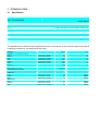
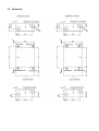
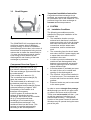
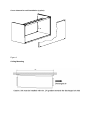
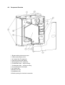
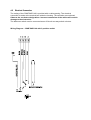
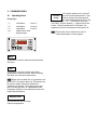
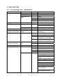
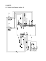
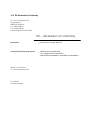
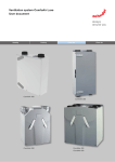
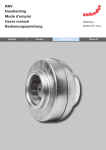
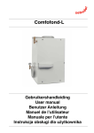
Comfoair 140
Manual
TABLE OF CONTENTS
1.
1.1
2.
2.1
2.2
2.3
3.
FOREWORD.................................................................................... 3
GENERAL ....................................................................................................... 3
SAFETY........................................................................................... 3
GENERAL SAFETY REGULATIONS .................................................................... 3
SAFETY PRECAUTIONS, SAFETY MEASURES .................................................... 4
INTENDED USE ............................................................................................... 4
TECHNICAL DATA ......................................................................... 5
3.1 SPECIFICATION ............................................................................................... 5
3.1.1 Technical Data ....................................................................................... 5
3.2 DIMENSIONS................................................................................................... 6
3.3 CIRCUIT DIAGRAM .......................................................................................... 7
4.
4.1
4.2
4.3
4.4
4.5
5.
5.1
5.2
5.3
6.
7.
7.1
7.2
8.
8.1
8.2
9.
10.
SYSTEM .......................................................................................... 7
INSTALLATION CONDITIONS ............................................................................. 7
TRANSPORT AND PACKAGING ......................................................................... 8
INSTALLATION................................................................................................. 8
COMPONENT OVERVIEW ............................................................................... 10
ELECTRICAL CONNECTION ............................................................................ 11
COMMISSIONING ......................................................................... 12
OPERATING PANEL ....................................................................................... 12
PROGRAMMING EXAMPLE ............................................................................. 14
SETTING PARAMETERS ................................................................................. 14
SETTING ....................................................................................... 17
MAINTENANCE / CARE ............................................................... 18
GENERAL ..................................................................................................... 18
FILTER CHANGING ........................................................................................ 18
MALFUNCTIONS .......................................................................... 19
TROUBLESHOOTING CHART – COMFOAIR 140 ............................................ 19
BYPASS INSPECTION INSTRUCTIONS ............................................................. 21
END OF LIFE PROVISIONS ......................................................... 21
ANNEXES .................................................................................. 22
10.1 ELECTRICAL CIRCUIT DIAGRAM – COMFOAIR 140 .......................................... 22
10.2 EC DECLARATION OF CONFORMITY .............................................................. 23
1. FOREWORD
This operating and installation manual contains
installation and operating instructions for the
COMFOAIR 140 heat recovery unit.
The warranty will be voided if:
• The unit is operated without filter,
• Proper filter maintenance is not carried out,
• Original spare parts were not used, or
unauthorised modifications were made to
the unit.
READ THIS MANUAL CAREFULLY BEFORE
PUTTING THE UNIT INTO OPERATION.
1.2
This manual contains all the information and
instructions necessary for optimum installation of
a heat recovery unit and the Comfoair 140. It
serves also as a manual for maintenance and
after-sales service work.
The Comfoair 140 ventilation unit was designed
for comfortable ventilation in residential buildings.
Use in any other way is considered as being an
unauthorised use that can result in damage to the
unit and/or injury to persons, for which the
manufacturer cannot be held responsible.
The unit is subject to ongoing improvement and
further development. It is therefore possible that
your unit differs slightly from the description here.
We wish you years of comfort and pleasure with
your Comfoair 140.
NOTE: This manual has been produced with the
greatest care and attention. However, no rights
can be derived from this. We reserve the right to
change the contents of this manual, in whole or in
part, at any time without prior notification.
The manufacturer assumes no liability for
damage or injury attributable to:
• Failure to observe the safety, operating and
maintenance instructions in this manual.
• The use of materials not supplied by the
manufacturer. The responsibility here lies
solely with the company installing the unit.
• Normal wear.
2. SAFETY
2.1
•
Comfoair 140 identification plate
•
•
The identification plate is located on the front
cover of the Comfoair 140.
1.1
General
Our “General Terms and Conditions” in their
latest wording apply to the CA 140.
The warranty period begins with commissioning,
but not later than one
month after delivery. This applies to material
replacement and does not include the labour. It
applies only on proof of maintenance having been
performed by a specialist company in accordance
with our instructions.
.
Liability
•
•
•
•
•
General Safety Regulations
Observe the safety regulations and warnings
contained in this manual at all times. Failure
to do so may result in damage to the unit or
personal injury.
The heat recovery unit and the Comfoair 140
must be installed in accordance with the
national building regulations, applicable
regulations of the local authorities and the
public utilities, the generally acknowledged
rules of engineering and the DIN standards in
their latest working.
Only an appropriately qualified company may
be employed to install and connect the unit
and to put it into operation.
Store this manual in the vicinity of the unit at
all times.
The instructions on periodic cleaning and/or
changing of the filters, the air inlet/outlet
valves and the air inlet/outlet grilles must be
strictly observed.
The proper response of the safety functions
and precautions must be checked at regular
intervals.
Modifications to the unit are not permitted.
The unit may only be connected to a 230 V
AC power supply!
2.2
•
•
2.3
Safety Precautions, Safety Measures
It must not be possible to touch the fan
wheels with your hand. The unit may
therefore only be operated with the duct
system connected. The unit cannot be
opened without the use of tools.
In conjunction with possible later warranty
claims and in order to ensure the proper
function of your system, we recommend that
you conclude a service contract with an
approved specialist company.
Intended Use
The Comfoair 140 is intended for the extraction of
polluted room air and the supply of warmed or
cooled fresh outside air. Use in any other way is
considered to be contrary to the intended use.
The manufacturer declines any responsibility for
damage, injury or other consequences resulting
from such use.
If used in the same building as open fires, the
relevant standards and regulations must be
observed by the installing company.
3. TECHNICAL DATA
3.1
Specification
3.1.1 Technical Data
COMFOAIR 140
Heat exchanger efficiency
approx. 92%
Fans
Constant volumetric flow with parallel flow technology
Voltage
230 V~, 50 Hz
Dimensions H x W X D
740 x 595 x 260 mm
Connection fittings
4x DN 125 mm
Weight
approx. 28 kg
Installation position
Wall or ceiling installation
Heat efficiency level
The standard unit is delivered as a right-hand version. A conversion of the unit from right to left, and as
a ceiling-mounted unit, is possible with little effort.
Display
Ventilation rate (default settings)
Low
Medium
High
Low
Medium
High
Maximum
Value
Unit
27
39
106
0.21
0.30
0.81
0.88
W
W
W
A
A
A
A
0.95-0.99
-
100 m³/h at 37 Pa
150 m³/h at 81 Pa
225 m³/h at 162 Pa
55
64
72
dB(A)
dB(A)
dB(A)
100 m³/h at 37 Pa
150 m³/h at 81 Pa
225 m³/h at 162 Pa
44
51
58
dB(A)
dB(A)
dB(A)
75 m³/h at
95 m³/h at
155 m³/h at
75 m³/h at
95 m³/h at
155 m³/h at
25 Pa
40 Pa
110 Pa
25 Pa
40 Pa
110 Pa
Power factor (cos phi)
Noise level (Lo=10-12W)
Intake air
Low
Medium
High
Exhaust air
Low
Medium
High
3.2
Dimensions
3.3
Circuit Diagram
*
*Important installation instruction
If a geothermal heat exchanger is not
provided, we recommend the installation
of a preheater unit for the outside air. This
prevents icing of the heat exchanger at
extreme ambient temperatures.
4. SYSTEM
4.1
Figure 1
The COMFOAIR 140 is equipped with an
anti-freeze system without additional
auxiliary energy. A sensor is installed in
the discharged air duct that, in the event of
the ambient air temperature being too low,
reduces the air intake fan electronically in
1% steps via the internal control system.
Less energy is thus drawn from the
discharged air and freezing of the heat
exchanger is prevented.
Component Overview Figure 1:
#
Exhausting
of polluted room air, e.g.
from kitchen, bathroom or toilet (A).
The heat exchanger (B) draws heat from
the exhausted air.
Fresh outside air is drawn in (C).
The counterflow heat exchanger (B)
heats the intaken air.
The fresh heated air is delivered i.a. to
the bedroom and living room (D).
The counterflow heat exchanger (B) has
a thermal efficiency of approx. 90%.
Post-heating of the intaken air is
therefore not necessary.
A 100% bypass (E) ensures that the
exhaust air bypasses the heat
exchanger. As a result, the cool outside
air (e.g. from geothermal heat
exchanger) is not heated by the
counterflow heat exchanger. Cool
outside air flows into the house. This
process is controlled automatically
according to the set temperature.
Installation Conditions
The following preconditions must be
satisfied for the proper installation of the
Comfoair 140:
• The installation location must be
selected such that there is sufficient
space around the unit for the air intake
and outlet connections, the electrical
connections and the waste water
connections, and for maintenance
work.
• The connecting lines for the air intake
and outlet, the 230 V power supply and
a waste water connection must be
available in the room.
• In order to prevent condensation, the
outside air and discharged air lines
between unit connection and outside
wall/roof opening must be insulated
vapour diffusion-tight.
• A double-walled or insulated part must
be used for the roof or outside wall
opening for the discharged air.
• The Comfoair 140 must be installed in
a frost-free room. The condensate line
must be laid frost-free and with a down
gradient.
• Extractor hoods may not be connected
to the same system.
In order to ensure draught-free passage
of air through your house, air gaps under
or grilles in the doors must be provided.
These must not be sealed, as then – just
as with the opening of windows (no or
reduced heat recovery) – the optimum
function of the system cannot be assured.
Windows may be opened during the warm
part of the year.
4.2
Transport and Packaging
Take the necessary care and attention when transporting and unpacking the unit. Damage to
the packaging must be recorded on the delivery note on receipt of the goods.
Dispose of the packaging materials in an environmentally safe manner.
4.3
Installation
Wall Mounting
Figure 2: Unit as “right-hand version”
Cover element for wall installation (option)
Figure 3
Ceiling Mounting
4.4
Component Overview
1 Bypass with synchronous motor
2 Intake and exhaust air fan
3 Air intake filter F6 (optional)
4 Operating panel with display
5 Discharged air PTC thermistor
6 Condensate drain – wall mounting
7 Condensate drain – ceiling mounting
8 Counterflow heat exchanger
9 Air intake filter
10 Exhaust air filter
11 Installation rails
12 Cable opening for electrical connection
4.5
Electrical Connection
The casing of the COMFOAIR 140 is provided with a cable opening. The electrical
connection is made at the terminal box inside the housing. The terminals are numbered.
Observe the conductor designations. Incorrect connection of the cables will result in
damage to the electronics.
The bathroom switch must be connected as an off-circuit two-way switch or button.
Wiring Diagram – COMFOAIR 140 with 3-position switch
5. COMMISSIONING
5.1
Operating Panel
Displays:
"1"
"2"
"3"
" xx "
"."
Ventilation
“Level 1”
Ventilation
“Level 2”
Ventilation
“Level 3”
Malfunction code
Bypass open
Menu
This button is used to activate and deactivate
the menu.
OK
This button is used to confirm set values /
parameters and menu points. When cleaning
the filters it is used as a reset button.
When the air intake fan is in operation, the
green LED “Air intake” lights up. This button can
be used to switch off the air intake fan if
windows are opened. The bypass opens and
has no further function. If a geothermal heat
exchanger (GHE) is used, always leave the air
intake fan switched on.
Summer time
No function with this unit type.
Comfort temperature
This button allows you to read off
the set comfort temperature. If you
wish to change this temperature,
the desired temperature can be set
with the buttons or . Press OK to store the
new value. If three dashes (---) appear when the
button “Comfort temperature” is pressed, the
bypass must first be activated in menu point 45.
Comfort
temp.
The device tries to achieve the set air
intake temperature via the bypass.
Menu structure
The following programmes can be selected using the buttons MENU,
,
and OK:
Display
Operating mode
User access
Service access
P1
No function
-
-
P2
Forced ventilation times
Yes
Yes
P3
Set fan speeds
No
Yes
P4
Set temperatures
No
Yes
P5
Display and change
status
No
Yes
P6
Display malfunctions
No
Yes
P7
Reset
No
Yes
Access to the menus P3 to P7 is possible only after entering the code 352. Changes to
the values are made at your own risk. The manufacturer accepts no warranty for
incorrectly entered values.
In the event of a malfunction, please contact your installer or Zehnder Service.
Access to the menus
Number
Button Display Description
1
2
3
4
5
6
7
8
9
10
11
12
13
Menu
▲
▲
▲
OK
▲
OK
▼
OK
▲
▲
▲
▲
P1
P2
" 1 -- -- "
" ? -- -- "
" -- ? -- "
" -- ? -- "
" -- -- ?."
" -- -- ? "
P3
P4
P5
P6
P7
No function
Time delays for forced ventilation
Access code necessary
First digit of code (3)
Second digit of code (5)
Third digit of code (2)
Ventilation levels
Temperatures
Status
Malfunction register
Reset
To quit the programme, press the MENU button several times until the current fan speed
level is displayed. If no further buttons are pressed, the programme stops after 5 minutes and
the current fan speed level is displayed again.
With menu P3, this procedure takes approx. 30 minutes.
5.2
Programming Example
Set the speed level “2” (normal ventilation) of the air intake fan to 40.
Number
1
2
3
4
5
6
7
8
9
10
11
12
13
14
15
16
5.3
Button
Display
Description
Menu
▲
▲
▲
OK
▲
OK
▼
OK
OK
▲
OK
▼
OK
MENU
MENU
P1
P2
" 1 -- -- "
" ? -- -- "
" -- ? -- "
" -- ? -- "
" -- -- ?."
" -- -- ? "
P3
P31
P35
50
40
P35
P3
1, 2 or 3
No function
Time delays for forced ventilation
Access code necessary (352)
First digit of code
Second digit of code
Third digit of code
Ventilation levels
Exhaust air fan “Low”
Select P35
Current setting
Select 40
Saves the value 40
Depending on the fan speed level
Setting Parameters
P1 No function
P2 Time delays
Number
Meaning
Min
Max
Default
Unit
21
Starting delay Level 3
(floating contact)
0
15
5
Min
22
Stopping delay Level 3
(floating contact)
0
120
30
Min
P3 Fan speed levels
Number
Meaning
Min
Max
Default
Unit
31
Exhaust air fan Level 1
15
98
30
%
32
Exhaust air fan Level 2
16
99
50
%
33
Exhaust air fan Level 3
17
100
90
%
34
Intake air fan Level 1
15
89
30
%
35
Intake air fan Level 2
16
99
50
%
Number
Meaning
Min
Max
Default
Unit
36
Intake air fan Level 3
17
100
90
%
37
Current level of exhaust air fan
current
value
%
38
Current level of intake air fan
current
value
%
P4 Temperatures
Number
Meaning
Min
Max
Default
Unit
41
42
Comfort temperature
28
40
18
18
°C
Post-heater enable temperature
15
5
43
GHE starting temperature low
0
15
7
°C
44
GHE starting temperature high
10
35
23
°C
45
Current value of T1 (outside air)
current
value
°C
46
Current value of T3 (exhaust air)
current
value
°C
47
Current value of T4 (discharged air)
current
value
°C
P5 Status – depends on type
Number
Meaning
0
1
Default
51
No function
-
-
0
52
No function
-
-
0
53
No function
-
-
0
54
Bypass installed
No
Yes
Yes
55
No function
-
-
0
With the COMFOAIR 140, parameters P51, P52, P53 and P55 must
always be set to “0” and P54 always set to “1”.
P6 Malfunction register
Number
Meaning
Display
61
Last malfunction
Code, see 8.1 “Alarm and malfunction displays”
62
Last malfunction
but one
Code, see 8.1 “Alarm and malfunction displays”
63
Last malfunction
but two
Code, see 8.1 “Alarm and malfunction displays”
°C
P7 Reset
Number
Meaning
0
1
Default
71
Acknowledge alarm / malfunction
status
No
acknowledg
ement
Acknowle
dgement
0
72
General acknowledgement: all
default values are automatically
reset
No
acknowledg
ement
Acknowle
dgement
0
With Reset P72, “P54” is set to “0”. This must therefore be set to “1” again.
For reading out malfunctions, see section 10.
P8 Auxiliary frost protection control
Number
Meaning
Min
Max
Default
81
Frost protection safety
1
4
2
0
240
60
Unit
1 = Very safe
2 = Safe
3 = Normal
82
4 = Low
Thawing time in minutes
Setting 0 = standard frost protection
control
Min
6. SETTING
Characteristic Diagram
Speed
20%
Qv
(m³/h)
65
30%
75
40%
85
50%
95
60%
110
70%
125
80%
140
90%
155
100%
170
Diagram 7.1
Constant volumetric flow fans:
The Comfoair 140 is equipped with parallel-flow fans with the latest constant volumetric
flow technology. This means that a precisely defined volume of air corresponds to every
percentage setting (see table above). Intermediate values have to be interpolated.
1.
2.
3.
4.
5.
6.
Close all doors and windows.
Close the room doors and check the through-flow openings (min. 12 cm² per l/s).
Check that both fans run at all speeds.
Check that the bypass is closed.
Switch the Comfoair 140 to level “2”.
A. Install the cup valves/grilles and set these according to the characteristics or the
reference dwelling.
OR
B. If no values are known, set the valves/grilles as far open as possible. Measure the
air flow rates. First the intake air, then the exhaust air. If the values differ by more
than +/- 10% from the nominal value and most of them are in the + range, then set
the valves/grilles so that they are all in the + range. If the values are in the – range,
then set the valves/grilles so that they are all in the – range. Leave one air intake
and one air outlet valve open.
The fan setting can then be changed at the display. In order to minimise energy
consumption, the values should be set as low as possible. Ensure that the
relationship between HIGH, MEDIUM and LOW remains constant. Use diagram 8-1
for this. Use menu P3 of the menu structure to change the speeds.
7. If the air flow rates now still differ too much, these can be set at the valves.
8. Check the complete system after having set all the valves.
9. Record all the measured and set values in the setting protocol.
10. Switch the Comfoair 140 to level LOW.
7. MAINTENANCE / CARE
7.1
General
Maintenance of the unit for the end user is limited to the periodic cleaning of the filters and
the intake / exhaust air valves and grilles. Twice a year, the texts “FIL” followed by “tEr”
appear alternately on the display as a reminder to clean the filters. Cleaning of the valves /
grilles is recommended at the same time as the cleaning of the filters. The system must not
be operated without filters. Switch off the unit at the three-position switch or mains power
switch before changing the filters.
7.2
Filter Changing
•
•
•
•
•
•
•
C
B
A
Fig. 9 - 1
Change the filters at least once a
year.
To change or clean the filter, loosen
the 6 screws (A). In the case of
ceiling-mounted units, the
condensate drain must also be
removed. Then remove the front
cover.
The unit is equipped as standard with
an outside air filter (A) and an
exhaust air filter (B) of Class G4.
Pull the filters out of the unit from the
front and clean using a vacuum
cleaner or replace.
Push the filter into the holder again
and check that it is seated correctly.
Fit the front cover again and secure it
with the screws. In the case of
ceiling-mounted units, fit the
condensate siphon again.
Switch on the unit again and cancel
the filter change display with the
button OK.
8. MALFUNCTIONS
8.1
Troubleshooting Chart – COMFOAIR 140
Fault/malfunction
None
All OFF
Symptom
Bypass rotates
Filter clogged
Bypass does not
rotate
Display
FiltEr/A1
A3
A4
E3
Voltage connected
No voltage
High air delivery
temperature in summer
Bypass remains
closed
A3
A4
A5
A7
Low air delivery
temperature in winter
Bypass remains
open
No or insufficient intake
air
Fan not running
E3
E2
E2
E3
Fan running
Check
Bypass
Filter
Bypass
Intake air PTC thermistor
Exhaust air PTC thermistor
Discharged air PTC thermistor
“Intake air” button
Fuse on pcb defective
Control pcb defective
Failure of mains voltage
3-position switch
Bypass Comfort
temperature
Intake air PTC thermistor
Exhaust air PTC thermistor
Malfunction in outside
temperature PTC thermistor
Malfunction in post-heater
temperature PTC thermistor
Bypass
Discharged air PTC thermistor
Comfort temperature
Fan defective
Fan power pack defective
Control pcb
PTC thermistor
Filter clogged
Valves clogged
Heat exchanger clogged by
soiling
Heat exchanger iced
- Deviation in PTC thermistor
- Control pcb
Fan soiled
Ducts clogged
Air intake fan speed reduced
due to frost risk
Air intake fan is switched off
due to extreme frost risk
Fault/malfunction
Symptom
Display
Check
No or insufficient
Fan not running
exhaust air; bathroom
or shower remains
damp for too long
Fan running
E1
E1
Loud noise
E1/E2
Fan defective
Fan pcb defective
Control pcb defective
Filter clogged
Valves/grilles clogged
Heat exchanger clogged
Fan soiled
Ducts clogged
Impeller binding or is
broken
Bearings defective
Fan running too fast. No
or insufficient intake /
exhaust air
Bypass flap jammed
Bypass motor defective
Siphon does not close
Air leaks at unit or duct
system
Valves/grilles not open
sufficiently
Valves/grilles not
correctly connected to
duct
Fan running too fast. No
or insufficient intake /
exhaust air
Siphon is empty
Drain clogged
Drain line leaking at the
collecting tray
Wiring fault
Switch defective
Control pcb
Fan
EMC filter
Air intake or air
exhaust fan
Bypass
Scraping noise
Whistling noise
Air flow noise
Condensation leak
3-position switch has
no function
E1/E2
Interference on TV/
stereo system
8.2
Bypass Inspection Instructions
If 230 V AC is measured between DO3H and N,
the flap must open / be open.
If 230 V AC is measured between DO4H and N,
the flap must close / be closed.
Check the connection between pcb and bypass.
Air intake and air exhaust fan
Check the fans for soiling or mechanical damage.
If the fault E1 and/or E2 is displayed, check the
wiring. If the wiring is OK, then the fan is defective.
The supply voltage to the fans is 230 V. The
control voltage of the fans lies between 0 and 10
V DC. This voltage can be measured at the
terminals AO1L and AO2L on the pcb.
Printed circuit boards
If the fans react to the 3-position switch and the
display shows no or wrong values, then the
display is defective. Check the connection
between display and pcb.
If the fans do not react and the display shows no
values, then the pcb or the operating panel is
defective.
If the pcb is replaced, the unit has to be set up
again. If a protocol of the last setting is available,
the set values can also be taken from the protocol.
PTC thermistor
Check the thermistor and the wiring. If they are
OK, the thermistor must be replaced. See table of
thermistor values.
Temp.°C -50 -40 -30 -20 -10
Ohm
Temp.°C
Ohm
0 10 20
25
515 567 624 684 747 815 886 961 1000
30
40
50
60
70
80
90 100
1040 1122 1209 1299 1392 1490 1591 1696
Heat exchanger
Inspect the heat exchanger for damage and
soiling. See also chapter “Maintenance / Care”.
Three-position switch
Check the function as follows:
Disconnect the cables at terminals L2 and L1 on
the pcb. The fans run at level “1”.
Connect terminals L3 and L2 on the pcb. The fans
run at level “2”.
Connect terminals L3 and L1 on the pcb. The fans
run at level “3”.
Filter
In the event of a filter malfunction, pull out the filters
and clean or replace. See also chapter 7
“Maintenance / Care”.
EMC
If the unit causes interference to the television or
stereo system, the EMC filter must be replaced.
9. END OF LIFE PROVISIONS
At the end of the unit’s service life, contact the
supplier for information on adequate disposal. The
statutory regulations in force at the time must be
observed.
10. ANNEXES
10.1 Electrical Circuit Diagram – Comfoair 140
10.2 EC Declaration of Conformity
J.E. Stork Ventilatoren B.V.
Lingenstraat 2
8028 PM Zwolle-NL
Tel.: 038-4296911
Fax: 038-4225694
Handelsregister Zwolle 22293
EC - declaration of conformity
Description
: Heat recovery unit type: G90-140
Conforms the following directives
: - Machine directive (98/37/EG)
- Low voltage directive (73/23/EEC)
- EMC directive (89/336/EEC, 92/31/EEC and 93/68/EEC)
Zwolle, 22 november
J.E. Stork Ventilatoren B.V.
E v Heuveln
General manager
Switzerland
Zehnder Comfosystems AG
Industriestraße 11
CH-8820 Wädenswil
Phone: +41 043 833 2020
Fax: +41 043 833 2021
e-mail: [email protected]
© zehnder comfosystems 849050528engels-1107
Germany
Zehnder GmbH
Comfosystems
Almweg 34
D-77933 LAHR
Phone: +49 07821 586 159
Fax: +49 07821 586 302
www.zehnder-online.de
info@comfosystems