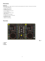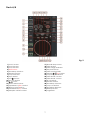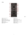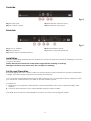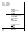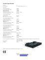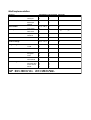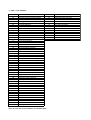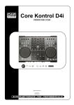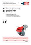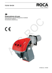
1
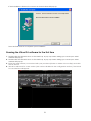
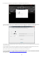
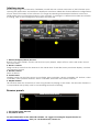
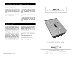
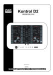
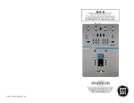
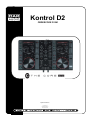
Kontrol D2 ORDERCODE D1261 Highlite International B.V. Vestastraat 2 6468 EX Kerkrade The Netherlands Congratulations! You have bought a great, innovative product from DAP Audio. The DAP Audio Kontrol D2 brings excitement to any venue. Whether you want simple plug-&-play action or a sophisticated show, this product provides the effect you need. You can rely on DAP Audio, for more excellent audio products. We design and manufacture professional audio equipment for the entertainment industry. New products are being launched regularly. We work hard to keep you, our customer, satisfied. For more information: [email protected] You can get some of the best quality, best priced products on the market from DAP Audio. So next time, turn to DAP Audio for more great audio equipment. Always get the best -- with DAP Audio ! Thank you! 1 DAP Audio DAP Audio Kontrol D2™ Product Guide Warning ....................................................................................................................................................................................3 Safety Instructions ...............................................................................................................................................................3 Operating Determinations ................................................................................................................................................4 Return Procedure ...............................................................................................................................................................5 Claims...................................................................................................................................................................................5 Description ...............................................................................................................................................................................6 Overview .............................................................................................................................................................................6 Deck A/B..............................................................................................................................................................................7 Mixer .....................................................................................................................................................................................8 Frontside ..............................................................................................................................................................................9 Backside ..............................................................................................................................................................................9 Installation ................................................................................................................................................................................9 Set Up and Operation .............................................................................................................................................................9 Names and Functions ...........................................................................................................................................................10 Deck Functions .................................................................................................................................................................10 Mixer Functions .................................................................................................................................................................11 Front Functions ..................................................................................................................................................................12 Back Functions ..................................................................................................................................................................12 Operations .............................................................................................................................................................................14 Selecting Folders...............................................................................................................................................................14 Selecting tracks using the track select encoder .........................................................................................................14 Starting Playback .............................................................................................................................................................14 Stop Playback ...................................................................................................................................................................14 Pausing...............................................................................................................................................................................14 Setting a Cue Point ..........................................................................................................................................................14 Setting a hot cue point in pause mode ........................................................................................................................14 Setting a hot cue point in play mode ...........................................................................................................................15 Deleting a hot cue point .................................................................................................................................................15 Cueing ...............................................................................................................................................................................15 Frame search ....................................................................................................................................................................15 Scanning (fast forward/fast backward) .......................................................................................................................15 Changing pitch of the song ...........................................................................................................................................15 Loop play...........................................................................................................................................................................16 Smart loop play ................................................................................................................................................................16 Reloop ................................................................................................................................................................................16 Recording a sample ........................................................................................................................................................16 Sample playback .............................................................................................................................................................16 Software Installation..............................................................................................................................................................17 Running the setup program. ...........................................................................................................................................18 Running the Virtual DJ-software for the first time ..............................................................................................................21 Interface zones .................................................................................................................................................................23 Browser panels ..................................................................................................................................................................23 Maintenance .........................................................................................................................................................................24 Troubleshooting .....................................................................................................................................................................24 Product Specification ...........................................................................................................................................................26 Appendix 1: Midi Implementation......................................................................................................................................27 2 Warning FOR YOUR OWN SAFETY, PLEASE READ THIS USER MANUAL CAREFULLY BEFORE YOUR INITIAL START-UP! Unpacking Instructions Immediately upon receiving this product, carefully unpack the carton and check the contents to ensure that all parts are present, and have been received in good condition. Notify the dealer immediately and retain packing material for inspection if any parts appear damaged from shipping or the carton itself shows signs of mishandling. Save the carton and all packing materials. In the event that a fixture must be returned to the factory, it is important that the fixture be returned in the original factory box and packing. Your shipment includes: • DAP Kontrol D2 • USB cable • CD with Virtual DJ LE software • User manual CAUTION! Keep this system away from rain and moisture! Safety Instructions Every person involved with the installation, operation and maintenance of this system has to: be qualified follow the instructions of this manual CAUTION! Be careful with your operations. With a dangerous voltage you can suffer a dangerous electric shock when touching the wires! Before you initial start-up, please make sure that there is no damage caused by transportation. Should there be any, consult your dealer and do not use the system. To maintain perfect condition and to ensure a safe operation, it is absolutely necessary for the user to follow the safety instructions and warning notes written in this manual. Please consider that damages caused by manual modifications to the system are not subject to warranty. This system contains no user-serviceable parts. Refer servicing to qualified technicians only. IMPORTANT: The manufacturer will not accept liability for any resulting damages caused by the nonobservance of this manual or any unauthorized modification to the system. Never remove warning or informative labels from the unit. Never leave any cables lying around. Do not connect this system to a dimmerpack. Do not switch the system on and off in short intervals, as this would reduce the system’s life. Do not open the device and do not modify the device. 3 Do not drive the inputs with a signal level bigger, than required to drive the equipment to full output. Only use system indoor, avoid contact with water or other liquids. Avoid flames and do not put close to flammable liquids or gases. Make sure you don’t use the wrong kind of cables or defective cables. When using a power adaptor, make sure that the available voltage is not higher than stated on the rear panel. Please turn off the power switch, when changing the power adaptor or signal cable. Extreme frequency boosts in connection with a high input signal level may lead to overdriving your equipment. Should this occur, it is necessary to reduce the input signal level by using the INPUT control. To emphasize a frequency range, you don’t necessarily have to move its respective control upward; try lowering surrounding frequency ranges instead. This way, you avoid causing the next piece of equipment in your sound path to overdrive. You also preserve valuable dynamic reserve (“headroom”) Avoid ground loops! Always be sure to connect the power amps and the mixing console to the same electrical circuit to ensure the same phase! If system is dropped or struck, disconnect the power supply or USB cable immediately. Have a qualified engineer inspect for safety before operating. If the system has been exposed to drastic temperature fluctuation (e.g. after transportation), do not switch it on immediately. The arising condensation water might damage your system. Leave the system switched off until it has reached room temperature. If your Dap Audio device fails to work properly, discontinue use immediately. Pack the unit securely (preferably in the original packing material), and return it to your Dap Audio dealer for service. Repairs, servicing and electric connection must be carried out by a qualified technician. For replacement use fuses of same type and rating only. Operating Determinations This system is not designed for permanent operation. Consistent operation breaks will ensure that the system will serve you for a long time without defects. If this system is operated in any other way, than the one described in this manual, the product may suffer damages and the warranty becomes void. Any other operation may lead to dangers like short-circuit, burns, electric shock, etc. You endanger your own safety and the safety of others! Improper installation can cause serious damage to people and property ! 4 Return Procedure Returned merchandise must be sent prepaid and in the original packing, call tags will not be issued. Package must be clearly labeled with a Return Authorization Number (RMA number). Products returned without an RMA number will be refused. Highlite will not accept the returned goods or any responsibility. Call Highlite 0031-455667723 or mail [email protected] and request an RMA prior to shipping the device. Be prepared to provide the model number, serial number and a brief description of the cause for the return. Be sure to properly pack the device, any shipping damage resulting from inadequate packaging is the customer’s responsibility. Highlite reserves the right to use its own discretion to repair or replace product(s). As a suggestion, proper UPS packing or double-boxing is always a safe method to use. Note: If you are given an RMA number, please include the following information on a piece of paper inside the box: 1) Your name 2) Your address 3) Your phone number 4) A brief description of the symptoms Claims The client has the obligation to check the delivered goods immediately upon delivery for any shortcomings and/or visible defects, or perform this check after our announcement that the goods are at their disposal. Damage incurred in shipping is the responsibility of the shipper; therefore the damage must be reported to the carrier upon receipt of merchandise. It is the customer's responsibility to notify and submit claims with the shipper in the event that a device is damaged due to shipping. Transportation damage has to be reported to us within one day after receipt of the delivery. Any return shipment has to be made post-paid at all times. Return shipments must be accompanied with a letter defining the reason for return shipment. Non-prepaid return shipments will be refused, unless otherwise agreed in writing. Complaints against us must be made known in writing or by fax within 10 working days after receipt of the invoice. After this period complaints will not be handled anymore. Complaints will only then be considered if the client has so far complied with all parts of the agreement, regardless of the agreement of which the obligation is resulting. 5 Description Features The Kontrol D2 is a DAP audio Core series Midi controller with a built-in 4 channel soundcard. • Pro quality jogwheel • Needle drop control • Seamless loop control • Smartloop buttons • Loop multiplier and divider • Hot cue buttons • 3 band EQ with kill function • USB interface • Plug & Play functionality • Including Virtual DJ LE software • Headphone output • Microphone input • 2 Built in soundcards Overview Fig. 1 1. Deck A 2. Mixer 3. Deck B 6 Deck A/B Fig. 2 1) Cue 1 button 2) Cue 2 button 3) Cue 3 button 4) Shift button 5) Smartloop 2 button 6) Reverse button 7) Loop in button 8) Sync button 9) Cue button 10) Set cue button 11) Button 12) Effect select button 13) Parameter 1/filter Control 14) Effects on/off button 15) Parameter 2/key control 16) Sampler volume control 17) Needle drop sensor 18) Pitch button 19) Pitch range indicator 20) Key lock button 21) Pitch control fader 22) Sample /rec button 23) Loop length indicator 24) Pitch bend + button 25) Pitch bend - button 26) x½/x2 switch 27) Scratch button 28) Smartloop 4 button 29) Loop out button 30) Smartloop 8 button 31) Reloop button 32) Jogwheel 7 Mixer Fig. 3 33) Track select encoder 34) Load A button 35) Channel 1 gain control 36) Channel 1 high control + kill LED 37) Channel 1 mid control + kill LED 38) Channel 1 low control + kill LED 39) Cue 1 button 40) Channel 1 fader 41) Crossfader slope switch 42) Crossfader 43) Load B button 44) Back button 45) Channel 2 gain control 46) Channel 2 high control + kill LED 47) Master control 48) Channel 2 Mid Control + kill LED 49) Cue mix control 50) Channel 2 Low Control + kill LED 51) Cue 2 button 52) Channel 2 Fader 8 Frontside Fig. 4 53) Mic input jack 54) Mic volume control 55) Headphone volume control 56) Headphone output jack Backside Fig. 5 57) DC In 5V 1000mA 58) USB connector 59) Master output unbalanced RCA 60) RCA/XLR select switch 61) Master output balanced XLR Installation Remove all packing materials from the Kontrol D2. Check that all foam and plastic padding is removed. Connect all cables. Always disconnect from electric mains power supply before cleaning or servicing. Damages caused by non-observance are not subject to warranty. Set Up and Operation Before plugging the unit in, always make sure that the power supply matches the product specification voltage. The power supply is printed on the back of the device. You can power the Kontrol D2 either by the USB connector or by an optional DC5V/1A adaptor in case your computer’s USB interface is not able to provide sufficient power. Connections 1 Make sure your computer’s USB interface can provide 500mA, else use the optional D1262 power adaptor. 2. Connect the Kontrol D2 to your mixer/amplifier using the proper cables. CAUTION: Be sure that the mixer/amplifier’s power is off, when connecting the cables. 9 Names and Functions Below is a description of the functions of the controls. Deck Functions 1. Cue 1 Button The Kontrol D2 allows you to store up to three hot cue points per deck. See page 14/15: ”7. Setting a hot cue point in pause mode” and “2. Setting a hot cue point in play mode”. 2. Cue 2 Button The Kontrol D2 allows you to store up to three hot cue points per deck. See page 14/15: “7. Setting a hot cue point in pause mode” and “2. Setting a hot cue point in play mode”. 3. Cue 3 Button The Kontrol D2 allows you to store up to three hot cue points per deck. See page 14/15: “7. Setting a hot cue point in pause mode” and “2. Setting a hot cue point in play mode”. 4. Shift button Pushing and holding this button gives you access to the secondary functions of the: parameter 1/filter (13) encoder, parameter 2/key (15) encoder, sample /rec (22) button and reverse/bleep (6) button 5. Smartloop 2 button Tapping this button starts a 2 beat loop. 6. Reverse button Use this button to toggle the reverse mode on or off. In reverse mode, the current track will be played backwards. 7. Loop in This button allows you to set the start point of the loop. 8. Sync button Automatically matches the corresponding deck’s tempo with the other deck’s tempo. 9. Cue button Push the cue button during playback to return to the position at which playback is started. 10. Set cue button This button will set the cue at the desired location. It will also return the audio to the last set cue position. Holding this button will also allow the user to preview the cue point until the button is released. 11. Play/pause button This button allows you to toggle between pause mode and playback mode. 12. Effects select button Tapping this button allows you to select between the available effects. The included Virtual DJ LE software gives you access to seven effects as shown below. Fig. 6 13. Parameter 1/filter control The Parameter 1 and 2 controls allow you to adjust effect parameters. Not all effects require two parameter controls. Push and hold the shift (4) button to adjust the filter frequency with this control. 14. Effect on/filter on button This button toggles the effect processor on or off. While pushing and holding the shift (4) button. The effect on button allows you to toggle the filter function on or off. 15. Parameter 2/key control The Parameter 1 and 2 controls allow you to adjust effect parameters. Note that not all effects require two parameter controls. While pushing and holding the shift (4) button. The control allows you change the key of the song while the tempo remains unchanged. 16. Sampler volume control/select button Allows you to adjust the sampler volume level. 10 17. Needle drop sensor The needle sensor gives you a graphic visualization of the playing time of the current song. Touching the sensor has the same effect as if you were lifting up the pickup arm of a conventional turntable and lower it somewhere else on the record. E.g. touching the needle drop sensor in the middle will continue playback in the mid of the song. 18. Pitch button This button allows you to select the maximum range for the pitch control fader. Fig. 7 19. Pitch range indicator Indicates the selected pitch range setup with the pitch (18) button. 20. Keylock button Allows you to toggle the Keylock mode on or off. In Keylock mode, the pitch fader allows you to Change the tempo of the song played back while the key of the song stays unchanged. 21. Pitch control fader Use this fader to adjust the pitch. Slide up to decrease the pitch, slide down to increase the pitch. 22. Sample /rec Button This button allows you to play/pause playback of the recorded sample. While pushing and holding the shift (4) button this button allows you to start/stop recording a sample. 23. Loop length indicator Indicates the length of the smartloop set up with the smartloop 2 (5), smartloop 4 (28), smartloop 8 (30) buttons and x½/x2 (26) switch. 24. Pitch bend + button The track speeds up while this button is pushed in. Release the button to return to the original BPM. 25. Pitch bend – button The track slows down while this button is pushed in. Release the button to return to the original BPM. 26. x½/x2 switch Allows you to divide or multiply the smartloop length by 2. 27. Scratch This button allows you to select or deselect scratch mode for the jogwheel. If the scratch mode is not selected, the jogwheel is in jog mode. 28. Smartloop 4 button Tapping this button starts a 4 beat loop. 29. Loop out This button allows you to set the endpoint of the loop. 30. Smartloop 8 button Tapping this button starts an 8 beat loop. 31. Reloop button This button allows you to either exit or call the Loop playback. 32. Jogwheel While not in scratch mode, the jogwheel allows you to speed up or slow down. In scratch mode the jog wheel can be used for scratch effects. Mixer Functions 33. Track select encoder Depending on the browser panel (see page 23) you’re in, you can use the encoder to select a certain track or folder. Confirm by pressing the encoder. 34. Load A button Pushing this button loads the selected track in deck A and activates the cue function for channel 1. The cue 1 (39) button will light up. 35. Channel 1 gain The gain control allows you to adjust the input-sensitivity for a channel. En thus optimally matching the incoming signals to the mixer’s internal operation level. 36/ 37/ 38. Channel 1 equalizer section (HI / MID / LOW) Use the 3 band equalizer to adjust the tone for each channel by using the Hi, Mid and Low controls. Push a control to kill (mute) the corresponding band. 11 39. Cue 1 button Tapping this button will allow the audio from that channel to be cued in the headphone. Selecting cue 1 will deselect cue 2. Please ensure that headphone volume (55) is not completely turned down. 40. Channel 1 fader The fader controls the volume of the corresponding channel. 41. X-Fader slope switch Allows you to select the response (cut/linear) of the crossfader. 42. Crossfader The crossfader allows you to mix smoothly from one source to another (only when both faders are up). 43. Load B button Pushing this button loads the selected track in deck B. 44. Back button This button in combination with the track select (33) encoder allows you to navigate the browser panels. See page 14: “1. Selecting folders” and “2. Selecting tracks” 45. Channel 2 gain The gain control allows you to adjust the input-sensitivity for a channel. En thus optimally matching the incoming signals to the mixer’s internal operation level. 46/ 48/ 50. Channel 2 equalizer section (HI / MID / LOW) Use the 3 band equalizer to adjust the tone for each channel by using the Hi, Mid and Low controls. Push a control to kill (mute) the corresponding band. 47. Master Level Use to adjust the volume level of the master RCA (60) or the master XLR (62) outputs. Note: This is an analog control and does not send MIDI commands. 49. Cue mix control Allows the user to hear mixed audio of the monitor (cue) audio and the program (master) audio in the headphones. When the knob is rotated to the left only the cue audio will be heard, when in the right position only the program audio will be heard. Note: This is an analog control and although it does send MIDI commands, this control is not represented in the Virtual DJ LE software GUI. 51. Cue 2 button This button when pressed will allow the audio from that channel to be cued in the headphone. Please ensure that headphone volume (55) control is not turned down completely. 52. Channel 2 fader The fader controls the volume of the corresponding channel. Front Functions 53. Microphone ¼” jack unbalanced microphone input. This input will only function with mono jacks. When using TRS jack, the input will not work. The microphone input is analog and can be used independent of the software used on your PC. 54. Microphone Volume Use to adjust the volume of the microphone channel. 55. Headphone Volume Is used to adjust your headphone volume level. 56. Headphone You can connect a pair of headphones with a minimum impedance of 32 Ohm to this stereo 1/4” jack. The jack should be wired as Tip=left, Ring=right and sleeve=ground. Back Functions 57. DC In 5V 1000mA In case your PC/ laptop/ Mac’s USB port can’t provide sufficient power for the Kontrol D2, we suggest powering the Kontrol D2 with the optional DAP audio D1262 power adaptor. 58. USB Connector To connect your Kontrol D2 to a PC / laptop/ Mac. 12 59. Audio RCA Out L/R Use these outputs to connect an amplifier/mixer with unbalanced inputs. 60. RCA/XLR select switch Allows you to route the master output to either the unbalanced RCA audio (59) outputs or the balanced master XLR (61) outputs. 64. Master XLR Out L/R Use these outputs to connect an amplifier with balanced inputs. 13 Operations Selecting Folders • Make sure you’re in the file system/ folder structure panel (see page 23). Push the back (44) button to return to the file system/ folder structure panel if you are in the file/ search results panel. Dial the track select (33) encoder to browse the folders. • Push the track select (33) encoder to open the desired folder. Now you’re in the file/ search results panel and are ready to select a track as described before. • Push the back (44) button to return to the file system/folder structure panel. Selecting tracks using the track select encoder • Make sure you have opened the desired folder as described in Selecting folders and that you are in the file/ search results panel (see page 23) • Dial the track select (33) encoder to browse the tracks. • Push the load A (34) button or the load B (43) button to load the track in respectively the A deck or the B deck. Starting Playback • Push the play/ pause (11) button during the pause or cue mode to start playback, the LED in the play/ pause (11) button lights up. • The point at which playback starts is automatically stored in the memory as the cue point. The CD player will return to the cue point when the cue (9) button is pressed. Stop Playback There are two ways to stop playback: • Push the play/ pause (11) button during playback to pause at that point. • Push the cue (9) button during playback to return to the cue point and enter pause condition. Pausing • Push the play/ pause (11) button to pause playback. • The play/ pause (11) button blinks when the pause mode is set. • Playback resumes when the play/ pause (11) button is pressed again. Setting a Cue Point • • • • Push the play/ pause (11) button to toggle between play mode and pause mode. The play/ pause indicator flashes as the deck is in pause mode. Dial the jogwheel (32) to go to the desired Cue point. Push the set cue (10) button and your cue point will be stored. The cue point will be indicated in the waveform display as shown in figure 8. • Push the play/ pause (11) button to continue playback. Setting a hot cue point in pause mode • • • • • • Push the play/ pause (11) button to stop playback. The play indicator flashes when the pause mode is set. Turn the jogwheel (32) to go to the desired Cue point. Push the desired hot cue (cue 1 (1)/ cue 2 (2)/ cue 3 (3)) button and your hot cue point will be stored. The stored hot cue point will be indicated in the Waveform display as shown in figure 8. Push the play/ pause (11) button to continue playback. 14 Setting a hot cue point in play mode • During play mode, push the desired hot cue (cue 1 (1)/ cue 2 (2)/ cue 3 (3)) button. • The hot cue point is stored while playback resumes. • The hot cue point will be indicated in the waveform display as shown in figure 8. Fig. 8 (Hot) Cue Points Deleting a hot cue point • Push and hold the shift (4) button while tapping the corresponding hot cue button (cue 1 (1), cue 2 (2) or cue 3 (3)) to delete a hotcue point. Cueing • "Cueing" is the action of preparing for playback. • Push the cue (9) button, the player will enter cue mode, the playback returns to the cue point and enter the deck will enter pause mode, the Cue (9) button lights up and the play/pause (11) button flashes. When the play/ pause (11) button is pushed, playback will start from the cue point. • If the cue (9) button is pushed after the search operation or the scanning operation, the playback returns to the cue point and the deck will enter pause mode. NOTE: While in cue mode, if the cue (9) button is pushed and hold, playback will start from the cue point, when the button is released, the player will return to the cue mode automatically, it allows you to check the cue point. Frame search • Frame search is a function for monitoring the sound at a certain section of the song and manually changing the position. Searching is used to set a start point with precision. • Dial the jogwheel (32) while in pause or cue mode to start searching. • While dialing the jogwheel (32), the point from which the sound output moves is a number of frames corresponding to the number of the milliseconds, and the time display in the waveform display also changes. • The search point moves in the forward direction when the jogwheel (32) is dialed clockwise. When the jogwheel (32) is dialed counterclockwise, the search point will move backward. Scanning (fast forward/fast backward) • The needle sensor (17) gives you a graphic visualization of the playing time of the current song. Touching the sensor has the same effect as if you were lifting up the pickup arm of a conventional turntable and lower it somewhere else on the record. E.g. touching the needle drop sensor in the middle will continue playback in the mid of the song. Changing pitch of the song There are three tools available for changing the BPM of the song: I. Use the pitch control fader to adjust the BPM. • Set the desired pitch bend range for the pitch control fader (21) by pushing the pitch (18) button. Make sure that the pitch control fader (21) is not deactivated (off LED lit). • Adjust the BPM by sliding the pitch control fader (21) up or down. 15 • Slide the pitch control fader (21) up to decrease BPM, or down to increase BPM. The adjustment range is +/- 8%, 16%, 50 or 100% depending on the range, set up with the pitch (18) button. II. Use the pitch bend buttons to change the BPM temporarily. • The BPM increases or decreases respectively while the pushing the pitch bend + (24) or pitch bend – (25) button. • The BPM increase depends on how long you hold the button. If you hold the button for about 5 seconds, the BPM will go to + 20% for pitch bend + (24) or - 20% for pitch bend – (25). If you tap the button, the BPM will only change a little so you can change the beat slightly without an audible change in the music. • The BPM will return to the BPM set with the pitch control fader (21) when you release the pitch bend + (24) and pitch bend – (25) buttons. III. Dial the jogwheel while in jog mode to change the BPM temporarily. • Dial the jogwheel (32) clockwise during play to increase the BPM and counterclockwise to decrease the BPM. The faster you turn the wheel, the more the BPM changes. The adjustment range is +/- 20%. • When you release the jogwheel (32), the track will return to the BPM set with the pitch control fader (21). Loop play • Push the loop in (7) button to set the loop start point the button will start blinking. • Push the loop out (29) button to set the loop end point. After the end point is set, the playback will enter the loop play from start point to end point repeatedly. Both the loop in (7) button and the loop out (29) button will blink. • Pushing the loop out (29) button while in loop play, allows you to change the endpoint by dialing the Jogwheel (32). The loop out (29) button will light up continuously. Confirm the new endpoint by pushing the loop out (29) button and both the loop in (7) button and the loop out (29) button will blink again, indicating loop play is active. • Push the reloop (31) button to cancel the loop play. The Loop indicator dims. • Using the loop adjustment (5/ 28/ 30) buttons and multiplier/divider (26) switch allows you to shorten or expand the length of the recorded loop while loop play is active. Smart loop play • Set the loop length using the smartloop 2 (5), smartloop 4 (28), smartloop 8 (30) buttons and the x½/x2 (26) switch. Smartloop play will start immediately. • Pushing the reloop (31) button will cancel smart loop play. Note: 1/1 equals one bar or 4 beats. When smart loop playback is active, the loop length is still editable by using the smartloop 2 (5), smartloop 4 (28), smartloop 8 (30) buttons and the x½/x2 (26) switch. Reloop • If you push the reloop (31) button, the song will return to the last selected loop. • Push the loop in (17) button over and over rapidly to start the loop again and again. • Push the reloop (31) button again, the loop play function is canceled. Recording a sample • Select a memory space in which you want to store your new sample by dialing the sample volume (16) control while at the same time pushing it in (push to select). • While pushing and holding the shift (4) button, push the sample /rec (22) button to start recording. • When finished recording, push the sample /rec (22) button again while pushing and holding the shift (4) button. Sample playback • Select a memory space which contains a sample by dialing the sample volume (16) control while at the same time pushing it in (push to select). • Push the sample /rec (22) button to toggle playback/pause of the sample. 16 Software Installation System requirements: PC Minimum system requirements: Intel® Pentium® 4 or AMD Athlon™ XP 1280x1024 resolution DirectX compatible soundcard 512MB RAM 50MB free on the hard drive Recommended system requirements: Intel® Core™ 2 or AMD Athlon™ X2 1280x1024 resolution Multi-channel DirectX compatible soundcard 1024MB RAM 200MB free on the hard drive Additional requirements for Video mixing: 2048MB (2GB) RAM ATI™ or NVIDIA® video card w/256MB of Dedicated DDR3 RAM Video card must support dual-screen output Supported Operating System: MINIMUM: Microsoft® Windows XP SP3 or newer RECOMMENDED: Microsoft® Windows 7 Professional 32-bit Microsoft® Windows 95, 98, ME, or older are not supported Mac Minimum system requirements: Intel® processor Mac OS X v10.5.x 1024x768 resolution CoreAudio compatible soundcard 1024MB RAM 50MB free on the hard drive Recommended system requirements: Intel® processor Mac OS X v10.6.x 1440x900 resolution Multi-channel Core Audio compatible soundcard 2048MB (2Gb) RAM 200MB free on the hard drive Additional requirements for video mixing: ATI™ or NVIDIA® video chipset w/256MB of Dedicated DDR3 RAM Video must support dual-screen output Supported Operating System and Processor Platforms: Minimum: Mac OS X v10.5 Leopard on Intel processor platform Recommended: Mac OS X v10.6.x Snow Leopard on Intel processor platform Apple® Mac OS X 10.4.x Tiger or older are not supported Motorola® (PowerBook® G4) processor platform or older are not supported 17 Installation procedure: Be sure to turn off the power supply to all equipment as well as the computer. Please connect the random USB cable to between Kontrol D2 and your computer. Set the power switch on the Kontrol D2 in USB position. Insert the CD-ROM into the computers CD-drive and follow the instructions. Running the setup program. Follow the steps below. 1. If the installation program on your CD doesn’t start up automatically, you have start by double clicking install_virtualdj_le_v7.0.5.rar on the CD. The screen shown below will pop up. Select the desired language and press next. 2. The welcome screen will pop up Press the next button when finished reading the screen. 18 3. Now the read me file as shown below will pop up. After reading, press the next button 19 4. The Start Installation screen will pop up. Press the next button. During installation, you will see the screen as shown below. 20 If the installation is finished, the screen as shown below will pop up. Press the finish button to complete your installation. Running the Virtual DJ-software for the first time 1. Double click the Virtual DJ icon on the desk top. A pop up screen asking you to enter your serial number will pop up. 2. Double click the Virtual DJ icon on the desk top. A pop up screen asking you to enter your serial number will pop up. 3. Enter the serial number you received with your purchase (sticker on inside CD-cover flap) and click the OK button. 4. Virtual DJ will check for a new version (this can be disabled in the configuration section). The Virtual DJ user interface will appear. 21 5. Click the Config button (upper right). The following screen will pop up. In the Sound Setup tab you can optimize the soundcard settings. We suggest the settings below which give you access to all outputs on your Kontrol D2. Other configurations can limit your outputs. To the right of the soundcard menu are two drop down menus to choose respectively the first and the second soundcard. In the example shown, the first two channels of the Kontrol D2’s internal soundcard are routed to the master outputs and second two channels are routed to the headphones output. When setup correctly, press the apply button and then press the OK button. For more possibilities, we suggest reading the Virtual DJ Quick guide. You can download the Virtual DJ Quick guide from: http://www.virtualdj.com/wiki/PDFManuals.html 22 Interface zones Before beginning to use Virtual DJ, familiarize yourself with the controls and zones of the Software. Upon opening the application, an interface is displayed. Interfaces called skins feature different configurations, layouts and functionality of the software. Let’s begin by selecting Internal Mixer interface to become familiar with the most important features of the software. To change to a different skin while the software is running, click on the Config menu and select the skins tab. 1. Browser/Sampler/ Effects/ Record Browse your music folders, create, edit and save your playlists, adjust effects, video and audio, record and save mixes. 2. Deck 1 Controls Drag and drop music from the browser to this virtual deck. Track title, beats per minute display, counters and transport control. 3. Deck 2 Controls Same as Deck 1. 4. Center Panel Multiple panels can provide access to crossfader, gain controllers, volume controllers, PFL buttons, video controllers, video preview windows, effect controllers, timecode and scratch interface. 5. Rhythm window This window tracks the waveform of each song loaded or playing on the decks. This area also features a Computer Beat Grid (CBG) used for visual mixing and beat matching. Browser panels 1. File System/Folder Structure 2. File/Search Results For more information on the Virtual DJ software, we suggest checking the Support Section on http://www.virtualdj.com/ . Here you can find manuals, forums etc. 23 Maintenance The DAP Audio Kontrol D2 requires almost no maintenance. However, you should keep the unit clean. Disconnect the mains power supply, and then wipe the cover with a damp cloth. Do not immerse in liquid. Do not use alcohol or solvents. Keep connections clean. Disconnect electric power, and then wipe the audio connections with a damp cloth. Make sure connections are thoroughly dry before linking equipment or supplying electric power. Troubleshooting Problem Controller is completely dead. Controller is not recognized in windows. Probable cause(s) No power. Remedy Check that power is switched on and the power adapter is plugged in. No driver installed. 1. Unplug all other USB cables and devices. 2. Plug in your controller’s USB cable. 3. Check if your driver (ME 800) is installed and running. Windows Vista & Windows 7: Start/Devices and Printers/. No sound from controller Incorrect soundcard settings. No sound from the controllers headphone output. Incorrect soundcard settings. No access to the controller’s built in soundcards during setup. Controller is not connected to your PC’s USB port or is switched off. Windows XP: Start/Control Panel/System/Device Manager/. Check the settings in the config menu. See page 21-22: Running the Virtual DJ-software for the first time of this manual. Check the settings in the config menu. See page 21-22: Running the Virtual DJ-software for the first time of this manual. 1. Check if your controller is switched in. 2. Check if the controller is connected to your PC 3. Check your USB cable. 24 After successful installation. The second time I start up the controller + software, the software does not react on the controller Windows memorizes the USB port the controller was connected to during installation. If you use another USB port, the windows will not recognize the controller. Use the USB port you used during installation. Virtual DJ pro does not react on the controller. No correct driver in folder devices. Window Vista & Windows 7: Make sure that c:\Users\{Username}\My Documents\VirtualDJ\Devices contains ME800.xml Window Windows XP: Make sure that c:\Documents and Settings\{Username}\ My Documents\VirtualDJ\Devices contains ME800.xml Mac OS X: Make sure that ./Users/{Username}/Documents/VirtualDJ/Devices contains ME800.xml File can be downloaded from http://www.highlite.nl Window Vista & Windows 7: Make sure that c:\Users\{Username}\My Documents\VirtualDJ\ Mappers\ contains Generic ME-800.xml Window Windows XP: Make sure that c:\Documents and Setttings\{Username}\ MyDocuments\VirtualDJ\Mappers\ contains Generic ME-800.xml Mac OS X: Make sure that ./Users/{Username}/Documents/VirtualDJ/Mappers/ contains Generic ME-800.xml File can be downloaded from http://www.highlite.nl Window Vista & Windows 7: Make sure that c:\Users\{Username}\My Documents\VirtualDJ\Skins\ contains ME800.zip Window Windows XP: Make sure that c:\Documents and Settings\{Username}\My Documents\VirtualDJ\Skins\ contains ME800.zip Mac OS X: Make sure that ./Users/{Username}/Documents/VirtualDJ/Skins/ contains ME800.zip File can be downloaded from http://www.highlite.nl Check the settings in the config menu. See page 21-22: Running the Virtual DJ-software for the first time of this manual. No correct mapping in folder mappers. No correct skin in folder skins. Sound from controller despite all faders are in minimum position. Incorrect soundcard settings. Install the driver again on the new USB port. 25 Product Specification Decks: Soundcard: 2 4.1, 24 bit, 96 kHz, 4 out, 1 in Mic input Input impedance: Full scale level @ 1 kHz: SNR (weighted): THD + N @ 1 kHz: Frequency response ± 1 dBu: Dynamic range codec: 600 Ω 50 mV -75 dB 0,75 % 100 Hz – 10 kHz 80 dBu Audio outputs (D/A) Sample rate: Bit resolution converter: 96 kHz 24 bit Line outputs (balanced XLR) Output impedance: Maximum output level: SNR (weighted): THD + N: Frequency response ± 1 dBu: Dynamic range codec: 10 kΩ 2,7 V -80 dBv 0,05 % 20 Hz – 20 kHz 90 dB Line outputs (balanced RCA) Output impedance: Maximum output level: SNR (weighted): THD + N: Frequency response ± 1 dBu: Dynamic range codec: 10 kΩ 2,7 V -80 dBv 0,05 % 20 Hz – 20 kHz 90 dB Headphone outputs (balanced XLR) Output impedance: Maximum output level: SNR (weighted): THD + N: Frequency response ± 1 dBu: Dynamic range codec: 16 Ω - 32 Ω 1,1 V -75 dBv 0,05 % 20 Hz – 20 kHz 90 dB Power rating and consumption: Dimension: Weight: 5Vdc 500mA (powered by either a USB port or optional power adapter D1262) 420 x 252 x 75mm 2,2kg Design and product specifications are subject to change without prior notice. Website: www.Dap-audio.info Email: [email protected] 26 Midi Implementation function basic channel Mode Transmitted Recognized Remarks X 1 X X Default Changed Default Messages Altered X X X X X X X X X *1 Pitch bend 01(16) -7D(16) X O X X X X Control change 00(16) - 21(16) X *2 True# X X X X X X Song pos Song Sel Tune Clock Commands Local ON/OFF All Notes OFF Active Sense Reset X X X X X X X X X X X X X X X X X X Note number Velocity After touch True voice Note ON Note OFF Key's Channel Prog Change SysEx Common System real time Aux Messages O:YES X:NO Mode 1: OMNI ON, POLY Mode 3: OMNI OFF, POLY Mode 2: OMNI ON, MONO Mode 4: OMNI OFF, MONO 00(16) = off, 7F(16) = on *1 table 1: note numbers note number 01 02 03 04 05 33 34 38 3B 3C 3F 40 43 44 47 49 4A 4B 4C 4D 4E 4F 50 51 52 53 54 55 56 57 58 59 5A 5B 5C 5D 5E 5F 60 61 62 63 64 65 66 67 68 69 6B 6C 6D function push mid encoder channel A (kill) push effect volume channel A (select) push effect volume channel B (select) touch jogwheel channel A touch jogwheel channel B cue buton channel A load B button key lock button channel A set cue button channel A cue buton channel B key lock button channel B sync button channel A play/pause button channel A set cue button channel B sync button channel B loop in buton channel A loop out button channel A load A button play/pause button channel B loop in buton channel B loop out button channel B push track select encoder push high encoder channel A (kill) push mid encoder channel B (kill) push high encoder channel B (kill) push low encoder channel A (kill) push low encoder channel B (kill) cue 1 button (mixer) cue 2 button (mixer) scratch button channel B crosfader curve switch "linear" crosfader curve switch "cutting" scratch button channel A back button smartloop 2 button channel B smartloop 4 button channel B smartloop 8 button channel B reloop button channel B x 2 channel B x 1/2 channel B cue 1 button channel B cue 2 button channel B cue 3 button channel B delete button channel B pitch button channel B pitch bend + button channel B pitch bend - button channel B reverse button channel B effect on/off button channel B rec sample button channel B smartloop 2 button channel A note number 6E 6F 72 73 74 75 76 77 78 79 7A 7B 7C 7D note: All note and control numbers are Hexadecimal! function smartloop 4 button channel A smartloop 8 button channel A x 1/2 channel A cue 1 button channel A cue 2 button channel A cue 3 button channel A delete button channel A pitch button channel A pitch bend + button channel A pitch bend - button channel A reverse button channel A effect select channel A effect on/off button channel A rec sample button channel A *2 table 2: control change numbers control change number 00 03 04 07 08 09 0A 0B 0C 0D 0E 0F 10 11 12 13 14 15 16 17 18 19 1A 20 21 function parameter 1 adjust channel A parameter 2 adjust channel A parameter 1 adjust channel B parameter 2 adjust channel B fader channel A fader channel B crossfader pitch fader channel A pitch fader channel B gain channel A gain channel B effect volume channel B hi level channel A hi level channel B mid level channel A mid level channel B low level channel A low level channel B needle drop channel B needle drop channel A jogwheel channel B jogwheel channel A track encoder cue/pgm mix effect volume channel A note: All note and control numbers are Hexadecimal! note 01/7F 01/7F 01/7F 01/7F 00-7F 00-7F 00-7F 00-7F 00-7F 00-7F 00-7F 00-7F 00-7F 00-7F 00-7F 00-7F 00-7F 00-7F 00-7F 00-7F 01/7F 01/7F 01/7F 00-7F 00-7F CW/CCW CW/CCW CW/CCW CW/CCW CW/CCW CW/CCW Forward/backwards