1
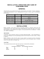
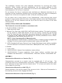
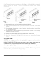
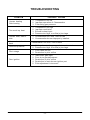
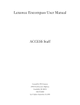
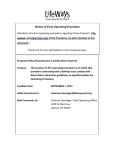
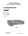
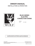
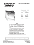
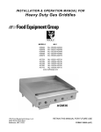
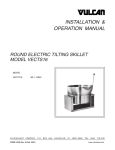
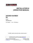
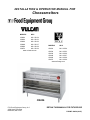
INSTALLATION & OPERATION MANUAL FOR
Cheesemelters
MODELS
MLS
VCM24
ML-135124
VCM34
ML-135123
VCM36
ML-135126
VCM48
ML-135127
VCM60
ML-135128
VCM72
ML-135129
www.vulcanhart.com
MODELS
MLS
CMJ24
ML-135124
CMJ34
ML-135123
CMJ36
ML-135126
CMJ48
ML-135127
CMJ60
ML-135128
CMJ72
ML-135129
www.wolfrange.com
CMJ36
ITW Food Equipment Group, LLC
3600 North Point Blvd.
Baltimore, MD 21222
RETAIN THIS MANUAL FOR FUTURE USE
FORM F-36954 (04-07)
IMPORTANT FOR YOUR SAFETY
THIS MANUAL HAS BEEN PREPARED FOR PERSONNEL QUALIFIED TO
INSTALL GAS EQUIPMENT, WHO SHOULD PERFORM THE INITIAL FIELD
START-UP AND ADJUSTMENTS OF THE EQUIPMENT COVERED BY THIS
MANUAL.
POST IN A PROMINENT LOCATION THE INSTRUCTIONS TO BE FOLLOWED IN
THE EVENT THE SMELL OF GAS IS DETECTED. THIS INFORMATION CAN BE
OBTAINED FROM THE LOCAL GAS SUPPLIER.
IMPORTANT
IN THE EVENT A GAS ODOR IS DETECTED, SHUT
DOWN UNITS AT MAIN SHUTOFF VALVE AND
CONTACT THE LOCAL GAS COMPANY OR GAS
SUPPLIER FOR SERVICE.
FOR YOUR SAFETY
DO NOT STORE OR USE GASOLINE OR OTHER
FLAMMABLE VAPORS OR LIQUIDS IN THE VICINITY OF
THIS OR ANY OTHER APPLIANCE.
WARNING: IMPROPER INSTALLATION, ADJUSTMENT,
ALTERATION, SERVICE OR MAINTENANCE CAN
CAUSE PROPERTY DAMAGE, INJURY OR DEATH.
READ
THE
INSTALLATION,
OPERATING
AND
MAINTENANCE INSTRUCTIONS THOROUGHLY BEFORE
INSTALLING OR SERVICING THIS EQUIPMENT.
IN THE EVENT OF A POWER FAILURE, DO NOT
ATTEMPT TO OPERATE THIS DEVICE.
-2-
INSTALLATION, OPERATION AND CARE OF
CHEESEMELTERS
GENERAL
Cheesemelters are produced with quality workmanship and material. Proper installation,
usage and maintenance of your Cheesemelter will result in many years of satisfactory
performance.
Model
# of Burners
BTU/hr Input Rating
VCM24 / CMJ24
1
18,000
VCM34 / CMJ34
1
24,000
VCM36 / CMJ36
1
24,000
VCM48 / CMJ48
2
36,000 (2 @ 18,000)
VCM60 / CMJ60
2
42,000 (1 @ 18,000 + 1 @ 24,000)
VCM72 / CMJ72
2
48,000 (2 @ 24,000)
INSTALLATION
Before installing, verify that the type of gas supply (natural or propane) agrees with the
specifications on the rating plate located underneath the grease drip pan. If the supply
and equipment requirements do not agree, do not proceed with the installation. Contact
your dealer immediately.
UNPACKING
Immediately after unpacking, check for possible shipping damage. If the cheesemelter is
found to be damaged, save the packaging material and contact the carrier within 15 days
of delivery.
Before installing, verify that the type of gas (natural or propane) and the clearance
dimensions (see page 4) agree with the specifications on the rating plate which is located
under the crumb tray on the right side.
LOCATION
The equipment area must be kept free and clear of combustible substances.
Back
Sides
Bottom
Minimum Clearances
Combustible Construction
Non-Combustible Construction
2"
0"
20"
0
10"
4"
-3-
The installation location must allow adequate clearances for servicing and proper
operation. While another gas-fired cheesemelter can be placed adjacent to this
Cheesemelter, there must be no obstruction to the front of the Cheesemelter. A minimum
front clearance of 36" (91 cm) is required.
Do not obstruct the flow of combustion and ventilation air. Adequate clearance for air
openings into the combustion chamber must be provided. Make sure there is an adequate
supply of air in the room to replace air taken out by the ventilating system.
Do not permit fans to blow directly at the Cheesemelter. Avoid wall-type fans which
create air cross currents within the room. Avoid open windows next to the Cheesemelter.
Maintain an 18" (46 cm) clearance from the top of the flue vent to the filters of the hood
venting system.
INSTALLATION CODES AND STANDARDS
The Charbroiler must be installed in accordance with:
In the United States of America:
1. State and local codes.
2. National Fuel Gas Code, ANSI-Z223.1/NFPA #54 (latest edition). This shall include but
not be limited to: NFPA #54 Section 10.3.5.2 for Venting. Copies may be obtained
from The American Gas Association Accredited Standards Committee Z223, @ 400
N. Capital St. NW, Washington, DC 20001 or the Secretary Standards Council, NFPA,
1 Batterymarch Park Quincy, MA 02169-7471
NOTE: In the Commonwealth of Massachusetts
All gas appliances vented through a ventilation hood or exhaust system equipped with
a damper or with a power means of exhaust shall comply with 248 CMR.
3. NFPA Standard # 96 Vapor Removal from Cooking Equipment, latest edition, available
from the National Fire Protection Association, Batterymarch Park, Quincy, MA 02269.
In Canada:
1. Local codes.
2. CAN/CSA-B149.1 Natural Gas Installation (latest edition)
3. CAN/CSA-B149.2 Propane Installation Code (latest edition), available from the
Canadian Gas Association, 178 Rexdale Blvd., Etobicoke, Ontario, Canada M9W 1R3
ASSEMBLY
Cheesemelters Mounted on a Counter (Fig. 1)
Cheesemelters mounted on a counter must be equipped with 4" (10 cm) legs. The
countertop must be of noncombustible construction. Place Cheesemelter in position, then
level. Unscrew the front legs from the chassis about 1 /4" (6 mm) and remove the lower
control panel for servicing.
Cheesemelters Mounted on a Wall (Fig. 2)
Secure brackets to the wall by means of lag screws or bolts. Make sure Cheesemelter is
level and lag screws or bolts engage wall studs.
Cheesemelter Mounted on Special Hi-Shelf (Fig. 3)
-4-
If the Cheesemelter is to be mounted over a Gas Range, a reinforced hi-shelf and special
mounting brackets are required. These are furnished when ordered as an elevated
Cheesemelter.
Fig. 1
Fig. 2
Fig. 3
1. Remove existing rear shelf and install the reinforced high shelf.
2. Install mounting brackets on both top corners of reinforced shelf, using the four bolts
provided.
3. Place and align Cheesemelter on top of brackets; place the back of the unit flush
with the rear of the shelf.
4. Using a #19 drill bit, drill from below through the four holes provided on the mounting
bracket into the base of the unit.
5. Drive four #10-24 self-tapping screws (provided) into the drilled holes.
6. Attach both Cheesemelter and high shelf to the common rear panel with self-tapping
screws.
GAS CONNECTIONS
CAUTION: Gas supply connections and any pipe joint compound must be resistant
to the action of propane gases.
Location of the gas inlet is at the top right rear corner of the top panel. Codes require that
a gas shutoff valve must be installed in the gas line ahead of the Cheesemelter.
Connect gas supply (1/2“pipe minimum recommended size). Make sure the pipes are
clean and free of obstructions.
Maximum line pressure for natural and propane gas is 14" W.C. Minimum line pressure is
7" W.C. for natural gas and 11" W.C. for propane gas.
-5-
GAS PRESSURE REGULATOR INSTALLATION
Gas regulator pressure is preset at 6” Water Column (W.C.) for natural gas, and 10” W.C.
for propane gas. Minor adjustments may be required based on site specific gas pressure.
Install the regulator as close to the cheesemelter on the gas supply line as possible.
Make sure that the arrow on the underside of the regulator is oriented in the direction of
gas flow to the cheesemelter (Fig. 2) and the regulator is positioned with the vent plug
and adjustment screw upright (Fig. 3).
Fig. 2
Fig. 3
The minimum supply pressure (upstream of the regulator) should be 7-9” W.C. for natural
gas and 11-12” W.C. for propane gas. At no time should the hotplate be connected to
supply pressure greater than ½ psig (3.45 kPa) or 14” W.C.
TESTING THE GAS SUPPLY SYSTEM
When gas supply pressure exceeds ½ psig (3.45 kPa), the Cheesemelter and its
individual shutoff valve must be disconnected from the gas supply piping system.
When gas supply pressure is ½ psig (3.45 kPa) or less, the Cheesemelter should be
isolated from the gas supply system by closing its individual manual shutoff valve.
FLUE CONNECTIONS
DO NOT obstruct flow of flue gases from the flue located on the rear of the Cheesemelter.
It is recommended that the flue gases be ventilated to the outside of the building through
a ventilation system installed by qualified personnel.
Information on the construction and installation of ventilating hoods may be obtained from
the standard for "Vapor Removal from Cooking Equipment," NFPA No. 96 (latest edition),
available from The National Fire Protection Association, Batterymarch Park, Quincy, MA
02269.
-6-
OPERATION
WARNING: THE CHEESEMELTER AND ITS PARTS ARE HOT. BE CAREFUL WHEN
OPERATING, CLEANING OR SERVICING THE CHEESEMELTER.
CONTROLS
Burner Valve
— the burner valve regulates the flow of gas throughout the
Cheesemelter. Gas flow is increased by turning the valve
counterclockwise. After preheating, the maximum output is not
required.
Turn the valve clockwise until the desired
performance is achieved.
Sliding Shelves (Rack) —
there are three rack positions. Place the shelf on the
rack needed for Cheesemelting. For deeper, longer heat, use
lower positions. For thinner foods, or faster cooking, use top
shelves.
Grease Pan (Drip Tray) —
the grease pan collects grease and waste. Do not allow
the grease pan to overflow. Empty the grease pan when threequarters full to reduce the possibility of spillage.
Pilot Adjustment Valve —
regulates the flow of gas to the pilot burner.
LIGHTING, RELIGHTING AND SHUTDOWN INSTRUCTIONS
1. Turn gas shutoff valve and burner valve to the OFF position and wait 5 minutes.
2. Turn gas shutoff valve ON. Light the pilot adjacent to the main burner. Adjust the pilot
valve screw until the pilot flame has a slight yellow tip.
3. After the pilot has been established, turn the burner valve to the ON position. The
burner flames may be adjusted, using the air shutters located behind the louvered
panel in the front of the broiler below the burner valve.
4. If the burners fail to light, turn off all valves, wait 5 minutes and repeat steps 1-3.
5. To shut down, turn the burner valves to the OFF position.
PREHEATING
Place the rack in its highest position.
Turn the burner valve knob completely
counterclockwise and preheat for 15 minutes.
RECIPE AND RACK ADJUSTMENT
Positioning the Cheesemelter rack is an important factor in the desired product end
results. Position the rack farther away from the burners for thick casseroles and for
melting cheese or butter to avoid drying the product. Position the rack closer to the
burners for bacon, toast and quick heating, but watch carefully to avoid burning.
-7-
LOADING AND UNLOADING
Place the rack in the desired position. Pull the rack out for loading. Load as quickly as
possible and avoid spillage. Push the rack into place and cook for the appropriate time.
Lower and pull the rack out for unloading.
CLEANING
Interior
When the Cheesemelter is cool, remove rack. Clean the rack and drip tray daily by
soaking in warm detergent water. Scrub with a stiff-bristled brush. Do not use harsh
abrasives.
After scrubbing, wash with soapy water, rinse and dry. Soap and water will normally do
the job. Heavy spattering or spillovers may require cleaning with mild cleaner or soapy
wet pads.
Exterior
When the Cheesemelter is cool, knobs and stainless steel surfaces may be cleaned with
mild soap and water applied with a damp cloth. Rinse the surface with clean water and
dry with a soft clean cloth. Do not use abrasive cleaners or strong liquid cleaners on
stainless steel surfaces as they may damage the finish.
Spray-On Cleaners
Be careful when using spray-on cleaners. Some cleaners may contain caustics. Please
follow cleaner manufacturer's instructions.
MAINTENANCE
WARNING: THE CHEESEMELTER AND ITS PARTS ARE HOT. BE CAREFUL WHEN
OPERATING, CLEANING OR SERVICING THE CHEESEMELTER.
LUBRICATION
All moving parts must be checked for wear and lubricated if necessary. Contact your local
Service Agency.
All valves and controls should be lubricated with a high-temperature grease by your local
Service Agency.
VENT
Annually, when the Cheesemelter is cool, check the flue and clear any obstructions.
SERVICE AND PARTS INFORMATION
Contact the Service Agency in your area to obtain service and parts information.
-8-
TROUBLESHOOTING
PROBLEM
POSSIBLE CAUSES
Uneven heating
Side burning
1. Temperature too low
2. Improper operation of Cheesemelter
3. Fluctuating gas pressure
Too much top heat
1.
2.
3.
4.
Uneven heat, side to
side
1. Cheesemelter not level, side to side
2. Cheesemelter burner improperly installed
Uneven heat, front to
back
Temperature too high
Improper ventilation
Excessive heat input
Pressure too high, or orifice(s) too large
Cheesemelter not level, front to back
Dried-out products
1. Melting time too long, or product too close to burners
2. Pressure too high, or orifice(s) too large
Pilot outage
1. Pilot flame too low
2. Restriction in pilot orifice
Poor ignition
1.
2.
3.
4.
5.
Insufficient gas input
Poor air-to-gas adjustment
Restriction in pilot orifice
Restriction in main burner ignition port
Pilot adjustment is incorrect
-9-