1
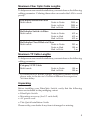
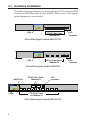
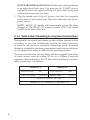
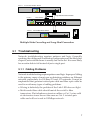
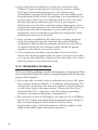
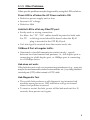
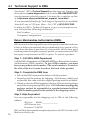
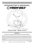
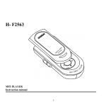
FiberOptic Switches
Quick Installation Guide
This quick installation guide provides instructions for installing a
FiberOptic Switch.
1-1 Introducing the FiberOptic Switches
SIIG's line of fiber optic switches are standard switches that meet all
IEEE 802.3u/802.3X standards. A Fast Ethernet Switch is a costeffective solution for easing your network congestion problems on
existing shared-hub network by breaking up the collision domain
and by multiplying the network performance. The overall network
transmission speed is increased and the network efficiency is improved
to accommodate high-bandwidth applications, such as imaging
multimedia, and CAD/CAM, etc.
The following models are available :
• FiberOptic Switch 4000-ST (4 ST fiber ports )
• FiberOptic Switch 4000-SC (4 SC fiber ports)
• FiberOptic Switch 4000-MT (4 MT-RJ fiber ports)
• FiberOptic Switch 8020-ST (8 TP & 2 ST fiber ports)
• FiberOptic Switch 8020-SC (8 TP & 2 SC fiber ports)
Features/Specifications
• Standards: IEEE 802.3u and 802.3x 100Base-FX
• Transmission Mode: Full or Half-duplex
• Transmission Speed: 10/100Mbps for TP ports
100Mbps for fiber ports
• Packet Forwarding/Filtering Rate: 148,000 packets/sec full
wire rate on 100Mbps forwarding and filtering. 14,880 packets/
sec full wire rate on 10Mbps forwarding & filtering
• MAC Address and Self-learning: up to 12K
• Buffer Memory: 1024KB
• Flow Control: IEEE 802.3x compliant for full-duplex;
Back pressure flow control for half-duplex
04-0184A
1
• Network Interface:
Models:
4000-ST :
Four 100Base-FX, ST (multi-mode)
4000-SC:
Four 100Base-FX, SC (multi-mode)
4000-MT:
Four 100Base-FX, MT-RJ (multi-mode)
8020-ST:
Eight 10/100Base-TX; RJ-45
Two 100Base-FX, ST (multi-mode)
8020-SC:
Eight 10/100Base-TX; RJ-45
Two 100Base-FX, SC (multi-mode)
• Fiber Optic Connector:
ST/SC/MT-RJ connector (multi-mode), Tx/Rx
• Fiber Optic Cable and Maximum Length:
50/125, 62.5/125 or 100/140 µm (multi-mode); up to 2000 m
• TP Connector: (For models 8020-ST and 8020-SC only)
• Selectable Duplex Mode Switch: Per fiber port FDX/HDX
DIP switch
• LED Indicators:
LED
Color
Link/Act Green
100Mbps Green
FDX/Col Amber
POWER
Green
Function
Lit when remote device connection is good
Blinks when any traffic is present
Lit when 100Mbps speed is active
Lit when full-duplex mode is active
Blinks when collision signal is present
Lit when AC power is ON and good
• Power Requirement:
AC Voltage: 100~240V
Frequency: 50~60Hz
Consumptions: Models 4000-ST/SC/MT: 25W Max.
Models 8020-ST/SC: 43W Max.
• Operating Temperature: 32° to 122° (0° to 50°C)
• Storage Temperature: -40° to 158°F (-40° to 70°C)
• Relative Humidity: 5% to 90%, non-condensing
• Dimensions:
Models 4000-ST/SC/MT: 45mm (H) x 330 (W) x 200mm (D)
Models 8020-ST/SC: 46mm (H) x 440 (W) x 220mm (D)
2
Maximum Fiber Optic Cable Lengths
To help ensure a successful installation, you must observe the following
cabling parameter. Violating these rules can render the LAN to work
poorly.
Full-duplex Switch via Fiber:
Multi-mode
Node to Node:
Node to Hub
Hub to Hub:
2000 m
2000 m
2000 m
Node to Node:
Node to Hub
Hub to Hub:
412 m
412 m
412 m
Half-duplex Class II Hub via Fiber:
Multi-mode
Node to Node:
Node to Hub
Hub to Hub:
205 m
100 m
5m
Half-duplex Switch via Fiber:
Multi-mode
Maximum TP Cable Lengths
To help ensure a successful installation, you must observe the following
cabling parameter.
Category 5 UTP Cable:
Multi-mode
Node to Node:
Hub to Hub:
100 m
100 m
* For connection to Router, Bridge, or regular 100Base-X Hub,
please refer to the device's Technical Manual for respective
bit-time delay.
Unpacking
Before installing your FiberOptic Switch, verify that the following
items are included in the packaging carton:
• FiberOptic Switch
• Mounting accessory (for 19" rack shelf)
• AC power cord
• This Quick Installation Guide
Please notify your dealer if any item is damaged or missing.
3
2-1 Hardware Installation
The following figures identify the front panel port, DIP switch and LED
locations for the FiberOptic Switch models. Please refer to the appropriate diagram for your model.
Fast Ether net Swit ching Hub
1
2
3
4
L i n k/ A ct
!
"
6 : 4:
6 : 4:
! "
1 0 0M b p s
.,:
0,:
F D X /C o l
PO W ER
6 : 4:
LEDs
6 : 4:
DIP
Switches
ST/SC Fiber Ports
100Base-FX
4-Port FiberOptic Switch 4000-ST/SC
Fast Ethernet Swit ching Hub
1
2
3
4
L i n k/ A c t
!
"
! "
1 0 0M b p s
.,:
F D X /C o l
0,:
PO W ER
LEDs
MT-RJ Fiber Ports
100Base-FX
4-Port FiberOptic Switch 4000-MT
ST/SC Fiber Ports
100Base-FX
1/MPR Port
10 /1 00 Swi tc hi ng
Hu b
A
Link/
B
A
DIP
Switches
B
FDX
100M
HDX
FD C
A
TX
RX
B
Link/
TX
RX
100M
FD C
X/
POW
1
LEDs
2
3
4
5
6
7
8
1/MPR
1/DT E
2
3
4
5
6
7
8
TP RJ-45 Ports
10/100Base-TX
8-Port FiberOptic Switch 8020-ST/SC
4
DIP
Switches
2-1.1 Fiber Port Full-/Half-duplex Mode Configuration
Each fiber port can be independently configured for either full-duplex
(FDX) or half-duplex (HDX) mode through DIP switches located on
the front panel. The default setting is Full-duplex.
• Verify that the duplex mode setting for each fiber port on
the Switch hub matches the connected remote device's mode
setting (full-duplex to full-duplex, half-duplex to half-duplex).
• The number on the DIP switch corresponds to the fiber port
number it sets.
To change a fiber port's mode setting , power down the Switch unit
and set the appropriate DIP switch. Then, power ON to set the new
configuration and status.
1 2
2
A1 B
3 4
FDX
FDX
HDX
HDX
Models 8020-ST/SC
Models 4000-ST/SC/MT
Default DIP Switch Settings
2-1.2 Network Device Connections
Proceed with the following steps to make the network connections:
1. Turn OFF the power to the server/host, workstation or any other
device to be connected.
2. Using Fiber Cable for 100Base-FX devices and Cat 5 TP Cable for
10/100Base-TX devices, connect each device to the appropriate fiber/RJ-45 ports on the Switch hub .
NOTE FOR FIBER CONNECTIONS: When connecting fiber
cable, you must make a paired connection to each fiber port.
Connect a cable between the selected Switch port's Tx (transmit)
port and the remote device's Rx (receive) port. Connect another
fiber cable between the Switch port's Rx (receive) port and the
device's Tx (transmit) port.
Tx Rx
Remote
Device
Switch Hub
Tx Rx
Tx Rx
Tx Rx
Tx/Rx Fiber Optic Cable Connections
5
NOTE FOR MODELS 8020-ST/SC: The fiber port can be up-linked
to an upper level hub's port. You may use the "1/MPR" port to
up-link the hub to an upper level hub's TP port. Only one up-link
is allowed between any two hubs.
3. Plug the female end of the AC power cord into the receptacle
on the back of the Switch unit. Plug the other end into an AC
power source.
NOTE: 4000-ST/SC models will automatically power ON when
plugged in. The 8020-ST/SC models provide a ON/OFF switch
control on the back of the unit.
2-1.3 Switch Hub Cascading & Long Haul Connections
Theoretically, the switch hub breaks up the collision domain in hub
cascading so you may unlimitedly up-link the hubs. However,
in practice, the network extension (cascading levels & overall
diameter) is limited by the timing requirement (time-out specification)
of your application software and network operating system.
The sum of all elements' bit-time delay and the overall bit-time delay
of wires/devices must be within 512 bit in a 100Base-X network
segment (collision domain). The TP, fiber cables and devices' bit-time
delay (round trip) is as follows:
100Base-TX
100Base-FX
DTE ↔ DTE:
100
DTE ↔ DTE:
100
Cat. 5 TP Wire:
1.112/m
Fiber Cable:
1.0/m
DTE FX to DTE TX: 100
100Base-TX to 100Base-FX Converter: 56
6
Level 1
4 Port Fiber ST/SC Switch
Fa s t E t he r n et S w it ch in g H ub
1
2
3
4
Li nk / Ac t
!
"
!
"
.,:
10 0M b ps
0, :
F DX /C ol
P O WE R
6 : 4 :
6 : 4 :
6 : 4 :
6 : 4 :
Long Haul Intra-hub connection
Level 22
Fiber Fiber
Switch
10/100 Swit ching
H b
A
Ln
i k/
1
2
3
Level 2
4
A
B
FDX
1 00 M
b
FD C
X/
l
L in k/
At
1 00 M
b
FD C
X/
POW
l
ER
B
5
HDX
6
A
B
7
8
TX
RX
1/MPR
1/DTE
TX
RX
2
3
4
5
6
7
8
4 Port Fiber ST/SC Switch
Fa s t E t he r n et S w it ch in g H ub
1
2
3
Li nk / Ac t
4
!
"
!
"
. ,:
10 0M b ps
0, :
F DX /C ol
P O WE R
6 : 4 :
6 : 4 :
6 : 4 :
6 : 4 :
File Server
Multiple Hubs Cascading and Long-Haul Connection
3-1 Troubleshooting
Network troubleshooting requires patience and logic. Generally
speaking, the cabling and workstation configurations are the likely first
suspects; network hardware is usually last on the list. It is more likely
for an entire hub to fail instead of just a single port.
3-1.1 Cabling Problems
Network troubleshooting requires patience and logic. Improper Cabling
is the primary cause of most non-workstation problems on Ethernet
network, particularly for 100 Base-TX and -FX networks. It must be
emphasized that genuine twisted-pair cable and fiber optic cable be
used to avoid many types of cabling problems.
• Wiring is definitely the problem if the Link LED does not light.
• Multi-mode fiber cable should match the switch’s fiber
transceiver. Flat telephone extension cables or Cat. 3 wires sold
at electronics stores are not the same as Cat. 5 twisted-pair
cable and will not work in 100Mbps network.
7
• If a workstation (workstation A) does not work and other
100Base-X ports on the hub are functioning, remove a fiber/
RJ-45 plug from a functioning port with a functioning
workstation (workstation B) and insert it into the suspect port.
If workstation B still works, the problem is in workstation A or
in the wiring. However, if workstation B does not work, then
the hub may have a defective port. Even if you suspect a
defective port on the hub, continue testing. Improperly wired
workstations may appear to be functional, especially if they are
located near the hub. Sometimes, a port connected to an
improperly wired workstation can function marginally while
another port may not work at all.
• Once you have established that the hub is working properly,
check all wiring between the hub and the malfunctioning
workstation. Ensure that the transmit and receive wires have
not been crossed; the two transmit wires should be paired
together as should the two receive wires.
• Use a continuity checker to ensure that wires do not have
breaks. By shorting together the two wires of a pair at one end,
you can use the continuity checker at the other end. Also, check
that there are no shorts between wires.
3-1.2 Workstation Problems
Most non-cabling problems result from improper configuration of the
network interface card (NIC) and its corresponding driver. The following
points will be helpful:
• Like other add-on cards in the workstation or server, NIC must
have unique memory address, I/O address, and interrupt. The
settings on a particular card must not conflict with the settings
on any other card in the same station. Please refer the User’s
manual of the NIC, computers, and Networking operating
systems to determine the proper configuration.
• The selection of half or full duplex, the speed of 10 or 100Mbps
for the NIC setting must match the mode and speed setting of
the corresponding port of the Hub. For NWay AutoNegotiation setting, both link partners will auto-adjust to the
highest allowable speed and mode operation.
8
3-1.3 Other Problems
Other specific problems may be diagnosed by using the LEDs, as below.
Power LED is off when the AC Power switch is ON:
• Defective power supply unit or fuse
• Incorrect AC voltage
• Defective Hub
Link/Act LED is off at any Fiber/TP port:
• Faulty node or wiring connection.
For fiber: the “TX”, “RX” cables should be paired at both ends
For TP: a clicking sound should be heard when the RJ-45
plug is inserted in the STP RJ-45 jack
• No Link signal is received from the remote node/site
100Base-X Port at irregular traffic:
• Abnormal or invalid transmission status (mode / speed)
between local and remote link partners, i.e., full-duplex port is
connecting to a half-duplex port, or 10Mbps port is connecting
to a 100Mbps device.
Hub does not work:
If the hub does not work or is experiencing interference (e.g., your site
may be located near radio station or transmitter, etc.), try using shielded
twisted-pair (STP) cable instead of UTP cable.
Hub Diagnostic Test
• The switch hub performs a self-diagnostic test at major hub
modules upon power on, LED indicators will go to normal
status if no problem occurred.
• To reset or restart the hub, power off the hub and wait for 10
seconds, then power on it again.
9
4-1 Technical Support & RMA
Questions? SIIG’s On-line Support has the answers! Simply visit
our web site at www.siig.com and click on the ON-LINE SUPPORT
icon for instant technical support. You may also e-mail us on-line
at: http:\www.siig.com/technical_support_form.html
If you need additional help, Tech Support Specialists are available
from 8:00 a.m. to 5:00 p.m. Mon. – Fri., PST at (510) 353-7542.
In order for SIIG’s Technical Support to give you prompt service,
you will need the following information.
Part Number: ______________________________________
Computer Configuration: ___________________________
Return Merchandise Authorization (RMA)
SIIG warrants to the original buyer of the product that the hardware
is free of defects in materials and workmanship for a period of five
years from the date of purchase. If your product fails to be in good
working order during the warranty period, you may return it to SIIG
for repair or replacement at SIIG's option. To return a product:
Step 1: Call SIIG's RMA Department
Call the RMA Department at (510) 413-5333for a Return Merchandise
Authorization (RMA) number. To get a RMA number, you must
have your product serial number. The serial number is located on
the side of the box it came in and on the back of the product.
Step 2: Complete the RMA form
• Fill out the RMA form and include it with the product.
• Properly pack the product for shipping. All software, cable(s) and
accessories that came with the original package must be included.
• Clearly write your RMA number on the top of the returned package
and on the accompanying RMA form. SIIG will refuse any shipping
package, and not be responsible for a product returned without
a RMA number posted on the outside of the shipping carton.
Step 3: Ship the product
You are responsible for the shipping cost to SIIG at the following
address:
SIIG, Inc. RMA#_______________
6078 Stewart Ave.
Fremont, CA 94538
SIIG will ship the repaired or replaced product via UPS Ground or US
Mail at no cost to you.
10