1
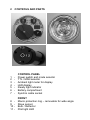
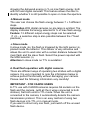
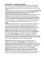
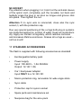
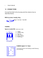
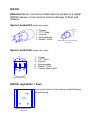
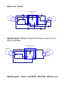
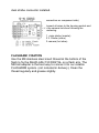
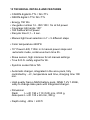
SEAFLASH 150DIGITAL
CANON
NIKON
USER MANUAL
CONTENT
1.
Warnings
2.
Controls and parts
3.
Compatible cameras
4.
General description
5.
Battery pack management
.a General
.b Battery recharge
.c Battery maintenance
6.
Shooting modes
.a E-TTL, I-TTL, Film-TTL
.b Manual
.c Slave
.d Dual flash operation
7.
Pilot light
8.
SOS safety mode
9.
Display error codes
10.
Maintenance
11.
Standard accessories
12.
Connections
13.
Technical details
14.
Warranty
15.
General
1 WARNINGS
• Never try to open the unit - the internal high voltage is
potentially lethal. The unit may be serviced only by
authorised service centres.
• Shooting a flash close to eyes can seriously injure them.
• Use only the original charging unit and TTL cable which are
delivered with the flash.
• Never connect two flashes together to a digital camera in a
different way than the one recommended in this manual. Not
strictly following the correct connections can result in a
damage of the strobes and the camera.
• Never connect the flash to a camera that is different from
the type listed in this manual. Before using the flash with a
camera not listed in this manual contact Seacam.
• Never connect a power adapter or battery charger to the
syncro connector.
• Never use this flash together with a different flash brand.
Enquire first about its compatibility and special connections.
Not following this can result a damage of the unit or the
camera.
• Never shoot the flash directly into the lens of a digital
camera. It can damage the camera picture sensor.
• Use the flash always following the directions of this user
manual.
• Not paying attention to the recommendations of this user
manual can cause damage to this unit or to the used
camera.
2
CONTROLS AND PARTS
1
2
3
4
5
6
7
-
CONTROL PANEL
Power switch and mode selector
TTL / MAN selector
Ambient light meter for display
LED display
Ready light indicator
Battery compartment
Synchro cable socket
8
9
10
11
-
FRONT
Macro protection ring – removable for wide angle
Slave sensor
Bulb / Reflector
Pilot light LED
12
13
14
15
16
-
BATTERY PACK
Power adapter socket
Recharger LED indicator
Data pin
minus (-) Battery pin
plus (+) Battery pin
3 COMPATIBLE CAMERAS
The SEAFLASH 150DIGITAL is suitable for CANON and NIKON
cameras. It is compatible with digital / film cameras in E-TTL,
I-TTL, film -TTL and in manual mode.
CANON
The SEAFLASH 150 DIGITAL is compatible with the following
CANON digital / film cameras listed in E-TTL, film-TTL and in
manual mode. By using digital cameras all the special functions
as, +/- flash compensation, automatic AF- light, pre exposure
lamps, automatic standby, etc. are supported.
CANON EOS1DS MKIII, EOS1D MKIII
CANON EOS1DS MKII, EOS1DNMKII, EOS1DMKII
CANON EOS1D, EOS1DS
CANON EOS5D
NIKON
The SEAFLASH 150 DIGITAL is compatible with the following
NIKON digital / film cameras listed in I-TTL, film-TTL and in
manual mode. By using digital cameras all the special functions
as, +/- flash compensation, automatic AF- light, pre exposure
lamps, automatic standby, etc. are supported.
NIKON D3X, D3
NIKON D2X, D2H, D2S
NIKON D700, D300, D200
NIKON D80, D70
4 GENERAL DESCRIPTION
The SEAFLASH 150 DIGITAL is fully controlled by a micro
processor. Some of the significant advantages of using a
micro controller are the possibility of managing digital
communication on a serial bus with a digital camera and the
possibility of easily updating the firmware in order to
guarantee compatibilities with future generation digital
picture cameras (if possible). An additional advantage offers
the digital display (4) which is the perfect interface between
the user and the flash.
Feature The display (4) and ready flash indicator (5) are
automatically dimmed by an ambient light photo diode (3).
With this feature the display retains its perfect visibility in
different light conditions.
In order to improve battery life and to make the battery
management very fast, easy and safe for the user a lot of
attention was given to the battery pack electronics.
This user manual contains important information. By reading it
carefully you will learn about the many advantageous features
of the flash which will help you take great pictures.
Firmware release number
When the unit is switched on the LED display (4) shows first the
firmware release number. A dot after the firmware release
number (.) indicates it is for CANON – no dot means it is for
NIKON.
5 BATTERY PACK MANAGEMENT
The SEACAM removable battery pack is located under the
battery container cap (6). Unscrew the cap by turning to the left
and close it by turning to the right.
Information You don’t need to tighten the cap very firmly.
Maintain / check the o-ring when opening and grease the
sealing surface regularly.
Attention Always prevent water or moisture from entering into
the battery container or into the batteries. Close the battery
container (6) before using the flash underwater. If no syncro
cable is connected, close also the syncro socket (7) with the
protection cap.
Feature The battery container is completely sealed. In case
water enters due to an incorrect battery cup positioning or an oring failure, the unit will not be floated. Only battery pack and
battery contacts can be damaged and have to be replaced.
The battery pack has to be inserted into the battery container
by aligning the 3 connecting pins. The battery fits only in one
position (with battery LED at 2h position). The battery pack has
to be removed by pulling up the metal ring to access the
battery charger socket.
The battery pack is made of special high current capable
Sanyo NiMH batteries. It is equipped with a built-in electronic
circuit to make battery management easy, fast and safe. By
switching on the flash the user can read the indication of the
battery status.
During normal use the micro processor checks the battery
status permanently and advises the user when it's close to
being completely discharged. The flash stops and automatically
switches off when the battery is fully discharged in order not to
damage it.
.a General
When the unit is switched on, the display shows first the
firmware release number. Shortly there-after it shows the
indication of available battery energy in 20% steps for two
seconds.
Information To have a more accurate reading, it is advised to
release the flash 2 or 3 times at full power, then switch the unit
off and on again. This second reading will give a more accurate
status of the battery energy level.
A 99% recharged battery pack can achieve ca.180 lamps at
max power.
With 40% power residual ca. 60 lamps at full power. This
should be enough capacity for one dive without recharging.
When the battery is down to 20% the display and the ready
flash indicator start to blink every minute for 4 seconds and an
audible alarm sounds once.
When the battery is completely discharged a continuous alarm
is emitted and two lines are shown on the display. After 30s the
unit automatically shuts off in order not to damage the battery.
If the flash is completely discharged and you try to switch it on
again, the flash can start a series of on/off cycles without
switching it on completely. Simply remove the battery pack and
recharge the battery.
Do not leave the battery inside the flash when flash is not in
use in order to avoid a slow and thorough battery discharge.
.b Battery recharge
Prior to the first use the battery must be fully charged before
disconnecting it from the power supply.
The battery can be recharged also if it is not fully discharged.
For charging the battery pack has to be removed from the
battery container and connected to the power supply.
After connecting the power adapter to the power adapter
socket (12), the charge process starts and the control LED (13)
starts to blink.
When the charging cycle ends the control LED (13) is
permanently lit and the battery enters into trickle charge. It can
now be disconnected from the power supply. (not necessary)
It takes approximately 100 minutes for the empty battery pack
to fully charge.
If an error is detected by the microprocessor, the charging
process is stopped immediately and the control LED (13) starts
to blink at a high frequency. In this case disconnect the power
adapter, wait for the battery to cool down. If the control LED (13)
recommences blinking at a high frequency the battery might be
defective and must be serviced or replaced.
For all new NiMH batteries or for battery packs stored for a
long time, a few full charge/discharge cycles (4-7) are
necessary to refresh the batteries for perfect conditions.
.c Battery maintenance
As for all NiMH battery it's advised to fully discharge the battery
when possible before charging it. To discharge the battery,
leave it inside the flash and switch it on in high pilot lamp (P1)
position. The flash will automatically shut off when the battery
is empty. The battery performance will increase after a few full
discharge/recharge cycles. If the battery pack is left inactive
for a short period of time it can be fully recharged and reach its
maximum energy level. After the recharge the display shows
99%.
Important To avoid batteries overcharge never try to recharge
a fully charged battery pack!
Attention Never perform a series of full power shoots to
discharge batteries. This will decrease flash lamp life and can
also result in a flash damage.
Never short circuit any battery terminals – it will damage the
battery pack!
6 SHOOTING MODES
Three different shooting modes are available.
Select with the TTL / MAN selector (2) TTL mode or any
manual setting - one aperture step up or down. With the power
and mode selector (1) switch between standard (ON,P1,P2) or
slave (SL) mode.
.a I-TTL , E-TTL, film-TTL
The energy delivered by the flash is calculated by the camera
to obtain the correct exposure. Set the TTL / MAN selector (2)
to TTL. The display shows the character A (TTL-mode). When
the flash delivers a full power lamp the user is advised of the
possible underexposure by an audible beep and EE blinking on
the LED display.
Feature After each shot the display blinks for 8 seconds,
showing the delivered energy in % on max flash energy, both
with film and digital cameras. This feature allows the user to
identify whether it is still possible to open or close the aperture.
.b Manual mode
The user can choose the flash energy between 7 + 5 different
steps.
Information With digital cameras no pre lamp is emitted. The
display indicates the energy selected in % of max flash energy.
Feature: 12 different output energy steps can be selected
(7 +5 – a sensitive stop is also possible between the 7 fixed
positions)
.c Slave mode
In slave mode (SL) the flash is triggered by the light sensor (9),
placed inside the reflector. This sensor is very sensitive and
allows the unit to work also with a certain distance between the
main flash and the slave flash. Select the power required with
the MAN selector (2).
Attention In slave mode no TTL is available!
d. Dual flash operation with digital cameras
There are different ways of operating two strobes with a digital
camera. It is very important to note the information below to
achieve perfect functionality without damaging your camera.
Please read the following information very carefully!
IMPORTANT - FOR CANON USERS
E-TTL use with CANON cameras requires S6 sockets on the
flash and the camera. (with all the 6 wires connected to both
strobes). Set both units to TTL mode. When the unit is
connected to the camera, it automatically detects the camera
transmission protocol. This is an easy method of using two
flash devices in E-TTL or in manual mode.
If you want to shoot only one flash, just switch off the unused
flash device.
IMPORTANT – FOR NIKON USERS
For I-TTL use with NIKON cameras S6 sockets on the flash
and the camera are recommended. Connect the main flash
(master) always to the left socket – the 2.flash (slave) to the right
socket.
If two strobes are used you have to use the dedicated SEACAM
- NIKON digital dual strobe connector (S-N DDSC). This
circuit has to be placed inside the housing.
When using 2 flash devices, the master controls the slave. The
master is directly connected to the camera (with all 6 wires
connected to the camera). It calculates the required energy for
the correct exposure and transmits the information by the TTL
cable to the slave. The master can operate in TTL(A) or MAN
mode, while the slave should always be left in the TTL(A)
mode.
If different energy levels are required from the two strobes, in
I-TTL mode, the user has to adjust the distance of the two
flashes from the subject to achieve the desired effect. In
manual mode the user can switch both flash devices to MAN
and then manually select the desired energy level steps.
Feature When setting the slave to TTL(A) the slave always
follows the main strobe in manual mode. If you need different
manual settings you have to adjust the devices separately.
By using the S-N DDSC circuit in your housing it is still
possible to connect an original Nikon SB flash to the left socket
on the camera housing. You will keep all features of the system
but the slave (SB) will work only in manual mode.
Important SEACAM suggests using two SEAFLASH
150DIGITAL only with the S-N DDSC circuit installed. This
system has been fully tested and has been proven to work well.
Using different flashes from the ones suggested can result in a
damage of the camera and flash devices. Before connecting
different flash brands enquire about their compatibility.
Attention On rare occasions during normal use the digital
camera can lose the communication with the flash. If this
happens, switch the camera and the flash off and on again in
order to reset the communication between the units. If the
problem occurs repeatedly check and clean the camera hot
shoe, the strobe connectors and wires.
Wires plugs and sockets must be absolutely dry to be working
flawlessly. Water inside the connectors can stop the data
transmission and TTL working mode.
7 PILOT LIGHT
A 3W power LED (11) generates a very bright pilot light. This
light beam of 10° allows an easy and perfect setting of the
flash. The Power LED has an output of about 180lm, equal to a
10W halogen bulb, and a life up to 100k hours. The LED will
never need to be replaced.
The pilot light is switched on with the power switch (1) and can
be set to 2 different light levels (P1,P2). P1 is the normal one
and P2 the reduced one.
Feature When the flash is connected to a digital camera the
automatic pilot light feature is available. The pilot light turns on
automatically when the camera auto focus system needs more
light to work. By setting set the power switch (1) to P1 or P2 you
change to permanent pilot light steps as selected.
With CANON digital camera you have to set the AF selector to
S and select the single shooting mode.
With NIKON digital camera you have to set the to AF selector
to – S or M. No automatic function in C.
Important The automatic auto focus assist light will work only
if the AF-illumination is activated in your camera menu. If you
don’t like this function deactivate it simply.
8 S.O.S. SAFETY MODE
For security reasons, to call attention your flash is equipped
with a true S.O.S. function. With the power switch (1) in the
SOS position a true S.O.S. light signal is generated. This
feature can also be used to test the flash.
Attention Use the S.O.S. signal only when really needed and
never use it to discharge the battery.
9 DISPLAY ERROR CODES
If an error is recognized by the micro processor, a code is
shown on the display, an audible alarm is emitted and all the
activities of the flash are stopped. This error information is used
to identify the cause and for security reason.
HI The temperature inside the flash is above 65°C. This
happens if the unit was left in the sun or in a hot place. Allow
the unit to cool down before switching it on again.
10 MAINTANANCE
Rinse your flash using fresh water after every dive in the sea
and dry it carefully. Clean with a mild cleaner and lubricate the
threads regularly.
S6 and N5 sockets require particular care and attention. Make
sure that the contacts are given regular inspection that the
plugs are clean and o-rings slightly lubricated.
S6 SOCKET
The S6 plug is a very safe and sturdy plug in system. Its
contact system is very precise and secure, combined with a 4
time o-ring sealing system which is easy to maintain. Plug in –
tighten the nut – ready to go!
N5 SOCKET
Pay attention when plugging it in; hold it at the anti-kink sleeve
of the spiral cord, completely pull the movable nut back and
tenderly press the plug in as soon as tongue and groove click
into place. Then tighten the nut.
Attention If no sync wire is connected, close also the sync
socket (7) with the protection cap.
Due very special positioning of the o-rings both plug in systems
are protected against re- suction of water. Keep all connections
dry. Apply our contact oil regularly, which reduces corrosion
and increases lifetime enormous. Grease all o-rings as usual –
not too much!
11 STANDARD ACCRESSORIES
The flash is supplied with following accessories as standard:
•
Exchangeable battery pack
•
Power supply
Input: 100-240V~ 1,5A 50/60Hz
Output: 12-14V 1.5A
•
Car / boat power adapter
Input ONLY to a 12-14V DC
•
Macro protection ring, removable for wide angle shots
•
Sync cable
•
Protection cap for syncro socket
•
Spare parts and maintenance set
•
Neoprene bag for the accu pack
•
User manual
12 CONNECTIONS
Connect the flash to the housing and the camera only as
described below.
Battery power supply plug
Input: 12-14V, 1.5A DC
CANON
Syncro socket S6 (wires rear view)
3
4
1 – Trigger
2 – Camera Data
3 – Ground
4 – TTL / Clock
5 – Ready / Clock
6 – Flash Data
6
5
2
1
Wires (rear) side
CANON digital 1/2 flash
3 GND
Connect all wires to the housing socket following
the numbering
1
4
6
2
5
Camera mounting foot, top wiew
NIKON
Attention Never connect two flash devices parallel to a digital
NIKON camera. It can result in serious damage of flash and
camera.
Syncro socket N5 (wires rear view)
1 – Trigger
2 – TTL / Data
3 – Ground
4 – Acknowledge
5 – Ready / Clock
5
1
4
2
3
Flash ca ble
1
5
2
4
3
Flash cable to the camera housing
Front view
Syncro socket S6 (wires rear view)
3
4
1 – Trigger
2 – TTL / Data
3 – Ground
4 – Acknowledge
5 – Ready / Clock
6 – II slave flash output
6
5
2
1
Wires (rear) side
NIKON digital/film 1 flash
Connect all wires to the housing socket following
the numbering.
4
3
1
5
2
Camera Mounting-foot
top view
Nikon film 2 flash
Camera Mounting-foot
top view
D1x
D2x
BAT46
5
1
BAT46
4
D1r
1
BAT46
2
3
5
1
4
4
2
3
5
3
2
D2r
D1
D2
BAT46
BAT46
BAT46
NIKON digital 2 flash no digital dual strobe connector (S-N
DDSC) installed.
Camera Mounting-foot
top view
Master flash
Slave flash
4
3
5
1
1
2
5
1
4
4
2
3
5
2
3
NIKON digital 2 flash S-N DDSC SEACAM - NIKON digital
dual strobe connector installed.
(connection on component side)
Connect all wires to the housing socket and
to the camera hot shoe following the
numbering
J1 main strobe (master)
J2 2. Strobe (slave)
J3 camera (hot shoe)
FLASHARM FIXATION
Use the M8 stainless steel insert thread at the bottom of the
flash to fix the SEAFLASH 150 DIGITAL on a flash arm. The
M8 ball adapter is the best way to connect it to our reliable
FLASHARM system. (not included in delivery). Clean the
thread regularly and grease slightly.
13 TECHNICAL DETAILS AND FEATURES
• CANON digital E-TTL / film-TTL
• NIKON digital I-TTL/ film-TTL
• Energy 150 Ws
• Uw-guide number 14 - ISO 100 / 1m at full power
• Coverage light angle 130°
• 180 flashes at full power
• Recycle time 0,1 – 2 sec.
• Manual light level selection in 7 + 5 different steps
• Color temperature 4400°K
• 10° Power LED, 110lm in 2 manual power steps and
automatic mode, continuous burn time 3h.
• Slave sensor, high intensive for all manual settings
• True S.O.S. safety signal for 6h.
• Synchro socket S6 or N5
• Automatic charger, integrated in the accu pack, fully
controlled by −ΔU, temperature and time, charging time 100
min.
• High quality Sanyo NiMH battery pack, NiMH 7.2V 1.85Ah,
easy to change akku pack with integrated charger.
• Dimension
Flash
L x Ø: 190 x 110 (120) mm, 2100 g,
Akku pack L x Ø: 135 x 40 mm, 300 g
• Depth rating -80m / 240 ft
14 WARRANTY
A 24 month warranty from the date of invoice for function and
tightness applies to the flash delivered. This warranty is valid
within the EU member countries – for non EU member
countries the warranty of the country to where the article is
delivered applies. Warranty repairs do not extend the warranty
time.
This warranty does not apply in the event of accidental
damage, negligence, improper handling, damage to cables,
water entering at improperly closed battery container cup or
connections, disregarding of operating conditions and
operating instructions, as well as unauthorized repairs or
changes by a third party.
Syncro cables, batteries, flash bulb and consumables parts are
not covered by warranty. If the warranty seal is broken the
warranty immediately expires.
SEACAM shall not be liable for direct or indirect damage to
persons and devices or (build in) cameras and reserves the
right to make technical changes or replacements.
15 GENERAL
If you have any question regarding this unit please contact us.
SEACAM service
C.v.Hoetzendorfstrasse 40
8570 Voitsberg
Austria
phone +43 / 3142 / 228850
telefax +43 /3142 / 228854
e-mail [email protected]
www.seacam.com
Revision: C-N- 08/08