1
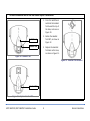
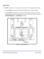
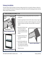
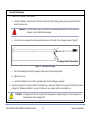
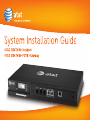
System Installation Guide AT&T SB67030 Deskset AT&T SB67010 PSTN Gateway Contents Contents..................................................................................................................................................................................................................................2 Parts List .................................................................................................................................................................................................................................3 System Installation Overview .......................................................................................................................................................................................4 Deskset Installation ...........................................................................................................................................................................................................5 Deskset Reset . . . . . . . . . . . . . . . . . . . . . . . . . . . . . . . . . . . . . . . . . . . . . . . . . . . . . . . . . . . . . . . . . . . . . . . . . . . . . 9 Gateway Installation ...................................................................................................................................................................................................... 10 Gateway Indicators. . . . . . . . . . . . . . . . . . . . . . . . . . . . . . . . . . . . . . . . . . . . . . . . . . . . . . . . . . . . . . . . . . . . . . . . 14 Configuration . . . . . . . . . . . . . . . . . . . . . . . . . . . . . . . . . . . . . . . . . . . . . . . . . . . . . . . . . . . . . . . . . . . . . . . . . . . . 14 Gateway Reset . . . . . . . . . . . . . . . . . . . . . . . . . . . . . . . . . . . . . . . . . . . . . . . . . . . . . . . . . . . . . . . . . . . . . . . . . . . 15 Web User Interface (WEBUI) Overview................................................................................................................................................................. 16 System Basic Settings . . . . . . . . . . . . . . . . . . . . . . . . . . . . . . . . . . . . . . . . . . . . . . . . . . . . . . . . . . . . . . . . . . . . . 17 Ring Groups . . . . . . . . . . . . . . . . . . . . . . . . . . . . . . . . . . . . . . . . . . . . . . . . . . . . . . . . . . . . . . . . . . . . . . . . . . . . . 18 Auto Attendant Overview . . . . . . . . . . . . . . . . . . . . . . . . . . . . . . . . . . . . . . . . . . . . . . . . . . . . . . . . . . . . . . . . . . 19 Recording User Name . . . . . . . . . . . . . . . . . . . . . . . . . . . . . . . . . . . . . . . . . . . . . . . . . . . . . . . . . . . . . . . . . . 19 Auto Attendant Configuration. . . . . . . . . . . . . . . . . . . . . . . . . . . . . . . . . . . . . . . . . . . . . . . . . . . . . . . . . . . . 20 Opening Menu Selection . . . . . . . . . . . . . . . . . . . . . . . . . . . . . . . . . . . . . . . . . . . . . . . . . . . . . . . . . . . . . . . . 21 Creating Auto Attendant Menus . . . . . . . . . . . . . . . . . . . . . . . . . . . . . . . . . . . . . . . . . . . . . . . . . . . . . . . . . . 22 Auto Attendant Voice Prompts . . . . . . . . . . . . . . . . . . . . . . . . . . . . . . . . . . . . . . . . . . . . . . . . . . . . . . . . . . . 24 System Directory . . . . . . . . . . . . . . . . . . . . . . . . . . . . . . . . . . . . . . . . . . . . . . . . . . . . . . . . . . . . . . . . . . . . . . . . . 25 Extension Basic Settings . . . . . . . . . . . . . . . . . . . . . . . . . . . . . . . . . . . . . . . . . . . . . . . . . . . . . . . . . . . . . . . . . . . 26 Product Registration ...................................................................................................................................................................................................... 27 AT&T SB67010/AT&T SB67030 Installation Guide 2 Contents Parts List Figure 1 illustrates the AT&T SB67010 PSTN Gateway parts. LINE 1 LINE 1 LINE 2 LINE 3 LINE 2 LINE 3 UP LINE 4 BYPASS DC 5.1V LAN RESET LINE 4 POWER DOWN SELECT - + CANCEL Gateway Grounding Cable Power Adapter Four Phone Cords RJ-45 Ethernet Cable Mounting brackets and screws Figure 1. Gateway Parts List Figure 2 illustrates the AT&T SB67030 Deskset parts. Deskset Base Deskset Stand Handset Power Adapter RJ-45 Ethernet Cable Handset Cord Figure 2. Deskset Parts List AT&T SB67010/AT&T SB67030 Installation Guide 3 Parts List System Installation Overview The instructions in this guide assume that you install one Deskset before installing the Gateway. The Gateway designates that Deskset as Extension 200. Figure 3 illustrates the minimum components needed to make the system work. NOTE: The system uses a Local Area Network (LAN) for system communication. It uses Public Switched Telephone Network (PSTN) phone lines for outside calls. Deskset Local Area Network (LAN) Gateway PSTN Plug Figure 3. Simplified System NOTE: You can register AT&T TL7600 Cordless Headsets and AT&T SB67040 Cordless Accessory Handsets to up to five Desksets. To integrate the Headset into the system, use the “AT&T TL7600 Cordless Headset User’s Guide” on the CD that came with this product, rather than the manual that is packaged with the Headset. AT&T SB67010/AT&T SB67030 Installation Guide 4 System Installation Overview Deskset Installation Option 1 Option 2 Install the SB67030 Deskset on a desktop or mount it on a wall. The desktop setup requires the Deskset Stand and provides two positions, Option 1 at 45° and Option 2 at 60°. If you use Option 2, rotate the Handset tab as explained in “To rotate the Handset tab for wall and Deskset Option 2 installation:” on page 8. To attach the Deskset stand: Insert Flexible Tabs Here Insert Solid Tabs Here 1. Place the Deskset on a flat surface with the power and network jacks facing you, as illustrated in Figure 4. 2. Locate the flexible tab side, illustrated in Figure 5. Rotate the stand so that the flexible tabs are away from you. Option 1 Option 2 3. Jacks 4. Flexible Tabs Figure 5. Deskset Stand Tabs Insert the solid tabs into the Option 1 or Option 2 slots on the base shown in Figure 4. Rotate the stand away from you until it rests against the base and you hear a click as it locks into place. Figure 4. Deskset Stand Installation AT&T SB67010/AT&T SB67030 Installation Guide 5 Deskset Installation To connect the RJ-45 Ethernet cable to the Deskset: With a PC connected to the network 1. Unplug the RJ-45 Ethernet cable from your computer. 2. Plug that RJ-45 Ethernet cable into the Network jack on the back of the Deskset indicated in Figure 6. 3. Plug another RJ-45 Ethernet cable into the PC jack on the Deskset indicated in Figure 6. 4. Plug the other end of that RJ-45 Ethernet cable into your computer. Without a PC connected to the network: Network PC Plug an RJ-45 Ethernet network cable into the Network jack on the back of the Deskset, indicated in Figure 6, and plug the other end into the Ethernet wall jack. Figure 6. Network Connections To connect power: 1. Plug the power adapter into the DC Power jack on the back of the Deskset, as indicated in Figure 7. 2. Plug the power adapter into an outlet not controlled by a wall switch. The display screen illuminates within about a minute. Power Jack CAUTION: To help prevent the loss of system data during power outages, plug the AC power plug into an Uninterruptible Power Supply (UPS). Figure 7. Power Connector AT&T SB67010/AT&T SB67030 Installation Guide 6 Deskset Installation To connect the corded Handset and an optional corded headset: Connect a corded handset: Handset Jack Handset Cord 1. Plug the coiled end of the handset cord into the handset jack on the left side of the telephone, as shown in Figure 8. 2. Plug the 5-inch straight end of the handset cord into the handset, then hang up. Connect an optional corded headset: 1. Plug an optional corded headset into the RJ9 connector indicated in Figure 9. 2. Press HEADSET to use the corded headset. Figure 8. Handset Plug The corded headset takes precedence over the cordless headset. Optional Corded Headset Jack Figure 9. Optional Headset Install CAUTION: Do not plug the corded headset into the jack for the corded handset. AT&T SB67010/AT&T SB67030 Installation Guide 7 Deskset Installation To rotate the Handset tab for wall and Deskset Option 2 installation: 1. Press the Switchhook and slide the Handset Tab toward the top of the base, as shown in Figure 10. 2. Rotate the Handset Tab 180°, as shown in Figure 12. 3. Replace the Handset Tab back on the base, as shown in Figure 11. Switchhook Handset Tab Figure 10. Handset Tab Figure 12. Handset Tab Rotation Handset Tab Figure 11. Replace Handset Tab AT&T SB67010/AT&T SB67030 Installation Guide 8 Deskset Installation Deskset Reset Press the RESET button shown in Figure 13 by inserting a pen or paper clip into the hole and applying pressure to the button. Pressing the RESET button for less than five seconds reboots the Deskset (your user settings are unaffected). Pressing the RESET button for more than five seconds resets the Deskset to factory defaults and clears the system configuration (your user settings, Personal directory list, and the extension number). This is a complete reset, unlike the Restore Default Settings option in Admin Settings on the Deskset. Reset Button Figure 13. AT&T SB67010/AT&T SB67030 Installation Guide Deskset Reset Button 9 Deskset Installation Gateway Installation The system requires at least one Gateway for receiving or making external calls. You can place the Gateway on a table top or mount it into a standard 19” metal rack. The Gateway must be installed within three feet of the building ground point. Install each Gateway using the following instructions. To mount the Gateway into a standard 19” rack: Mounting Screws Locating Indent 1. Remove the two Gateway mounting brackets and six screws from the packing tissue. 2. Position the right bracket at the front of the chassis, as shown in Figure 14. 3. Place the bracket on the chassis so that the locating indent on the bracket matches the indent on the chassis. This ensures that the screw holes are aligned. 4. Insert each of the three screws into the holes indicated in Figure 16 and tighten securely. Repeat the process for the left bracket. 5. Position the Gateway into the 19” metal rack, as shown in Figure 15. 6. Insert the top mounting screw (not included) in one side and turn it several turns to establish support. Repeat for the other side. Mounting Bracket Figure 14. Rack-mount Bracket 7. Figure 16. Bracket Installed Tighten the screws. Figure 15. Rack Installation AT&T SB67010/AT&T SB67030 Installation Guide 10 Gateway Installation To install the Gateway: 1. Connect the Gateway to Earth ground: a. Locate the Gateway within three feet (91.44 centimeters) of the building ground point, usually located at the electrical breaker box. WARNING: If you are unsure about the location of the building ground point or how to ground the Gateway, contact the facilities manager. b. Loosen the screw retaining the silver grounding terminal on the back of the Gateway shown in Figure 17. Grounding Terminal (Back Panel) Figure 17. Gateway Grounding 2. c. Insert the spade/fork end of the grounding cable under the grounding terminal. d. Tighten the screw. e. Connect the alligator clip end of the grounding cable to the building ground point. Plug the AC plug into an electrical outlet not controlled by a wall switch and the DC plug into the DC5.1V jack, shown in Figure 18 "Gateway Installation " on page 12. Wait up to one minute until the screen lights up. CAUTION: To help prevent the loss of system data during power outages, plug the AC power plug into an Uninterruptible Power Supply (UPS). AT&T SB67010/AT&T SB67030 Installation Guide 11 Gateway Installation To install the Gateway: (Continued) 3. Plug an RJ-45 Ethernet cable into the RJ-45 Ethernet port marked LAN. Plug the other end of the RJ-45 Ethernet cable into your office LAN. CAUTION: Some DHCP servers have default settings that limit the number of IP addresses. Each Deskset, Gateway, and personal computer needs an IP address. Confirm that the IP range of your DHCP server is sufficient to accommodate all of your devices. Consult the IT department or the person that installed this system if you need help checking the DHCP server. AC Plug Screen LINE 1 through LINE 4 BYPASS LAN DC 5.1V DC Plug Figure 18. Gateway Installation The Gateway Power-up Initialization sequence follows: z About 20 seconds after turning on power to the Gateway, the POWER LED turns on, and the Initializing message displays on the screen a few seconds later. z When the Gateway connects to the network, the message screen displays the Synchronizing screen to indicate that the Gateway is in the process of detecting and synchronizing with other devices on the network. z Once the Gateway has successfully finished synchronizing with the rest of the system, the Idle screen updates with the time, date and the IP Address. NOTE: The time and date may not be correct. See “System Basic Settings” on page 17 for information on setting the time and day. AT&T SB67010/AT&T SB67030 Installation Guide 12 Gateway Installation To install the Gateway: (Continued) 4. Remove the plastic covers from the PSTN (telephone) ports that will be used, marked LINE 1 through LINE 4, and the BYPASS jack. CAUTION: If you subscribe to Digital Subscriber Line (DSL) high-speed Internet service through your telephone line, you must plug each DSL telephone line into a DSL filter. Then plug the DSL filter into the telephone wall jack, as shown in Figure 19. 5. Plug up to four telephone lines from the wall jacks into the Gateway. The line LEDs will blink for up to 15 seconds during initialization. Figure 19. DSL Connection NOTE: For communication during power outages, plug an analog telephone into the BYPASS jack and a PSTN line into Line 4. NOTE: When your installation is complete, back up the Deskset settings. . See “Backup and Restore Settings” in the “SB67010 PSTN Gateway, SB67030 Deskset System Administrator’s Guide”. NOTE: For customer service or product information, contact the installer at the number on the cover of this guide. If your installer is unavailable, visit our website at www.telephones.att.com or call 1 (888) 916-2007. In Canada dial 1 (888) 883-2474. AT&T SB67010/AT&T SB67030 Installation Guide 13 Gateway Installation Gateway Indicators Figure 20 provides an illustration of the Gateway display and indicators. Line LEDs indicate the following status for each PSTN line: Red Disconnected Off Connected Green steady In use Line LEDs Power LED Menu Navigation Figure 20. Gateway Indicators and Controls Green flashing quickly Ringing Configuration The Gateway searches for a Dynamic Host Configuration Protocol (DHCP) server and automatically assigns the IP address and configures the system. You can use either the Gateway menu or the WEBUI for configuration. This document describes using the WEBUI starting on page 16, which is more convenient. Refer to the “SB67010 PSTN Gateway, SB67030 Deskset System Administrator’s Guide” for information on configuration using the Gateway menu. CAUTION: AT&T does not recommend using a Static IP. Contact the installer at the number on the cover of this guide if static IP editing is required. AT&T SB67010/AT&T SB67030 Installation Guide 14 Gateway Installation Gateway Reset Press the RESET button shown in Figure 21 by inserting a pen or paper clip into the hole and applying pressure to the button. Pressing the RESET button for less than five seconds reboots the Gateway (your system settings are unaffected). Pressing the RESET button for more than five seconds resets the Gateway to factory defaults and clears the system configuration (Auto Attendant settings, Ring Groups, Hold message, and System Directory). LINE 1 LINE 1 LINE 2 LINE 3 LINE 4 BYPASS LINE 2 LINE 3 UP RESET LINE 4 POWER DOWN SELECT DC 5.1V LAN - + CANCEL Reset Button Figure 21. AT&T SB67010/AT&T SB67030 Installation Guide Gateway Reset Button 15 Gateway Installation Web User Interface (WEBUI) Overview Once a Gateway and at least one Deskset are connected to the LAN, you can use the Web User Interface (WEBUI) to administer the system. Only one person should log in as System Administrator at a time to prevent accidentally overwriting and losing intended changes. To access the Browser Interface: IP Address 1. On your Deskset, click MENU. 2. To display the Deskset Information screen shown in Figure 22, press 4 on the dial pad. 3. Find your IP Address on the Deskset Information screen. 4. Open a browser on a PC on the same network as the Deskset. AT&T recommends Internet Explorer 6 or higher for best performance. Figure 22. Deskset Information Screen 5. IP Address 6. Figure 23. Browser Entry AT&T SB67010/AT&T SB67030 Installation Guide Figure 24. Login Type the Deskset IP address in the address bar, as show in Figure 23, and press ENTER. The Browser displays a login screen, as shown in Figure 24. Enter admin in the Login Name: field and 12345 in the Password field, then click . You may change your User ID and password once you are logged in. 16 Web User Interface (WEBUI) Overview System Basic Settings To view or modify the system basic settings: 1. To access the System Basic Settings menu as shown in Figure 25, click Basic Settings in the left navigation menu. Optional: Change the Administrator User ID and/or Administrator Password. z Optional: Any Deskset can be designated as the operator station. Incoming calls are forwarded to the operator station if the caller presses 0 (zero) while in the Auto Attendant. z Optional: The Telephone Line To Telephone Line Call Timer allows you to limit the duration of calls forwarded to outside lines, which occupy two phone lines. The administrator controls whether calls are allowed to be forwarded to outside lines. See the “SB67010 PSTN Gateway, SB67030 Deskset System Administrator’s Guide” for more information on these settings. 2. Click the Set Time by NTP Server button: AT&T recommends that the Desksets get the time and date they display from the online NTP server, although there are other choices on this screen: Figure 25. System Basic Settings Menu AT&T SB67010/AT&T SB67030 Installation Guide 3. a. The system defaults to Set Time by NTP Server. b. Select your time zone from the Time Zone drop-down menu. c. Click the Yes or No button for Daylight Savings Time:. Click 17 . Web User Interface (WEBUI) Overview Ring Groups Extensions can be grouped together to form up to 10 ring groups. For example, all extensions in the sales department could be defined as a ring group. You cannot call a ring group internally. To forward incoming calls to a particular ring group, use the Auto Attendant (see “Creating Auto Attendant Menus” on page 22). When the call is forwarded, all extensions assigned to the group ring. Designate one extension in the Ring Group to record a voicemail message when no phones in the ring group answer a call. To change the Ring Group settings: 1. Click System Settings in the left navigation menu and then click Ring Groups. 2. To name a new ring group and add extensions to the group, click to display the screen shown in Figure 26. Fill in the desired fields on that screen. 3. To add extensions to the group, highlight the extensions in the Available Extensions box and click . 4. When you are done, click . The new ring group appears on the Ring Groups Summary page. Figure 26. Ring Group Settings AT&T SB67010/AT&T SB67030 Installation Guide 18 Web User Interface (WEBUI) Overview Auto Attendant Overview Use the Auto Attendant to automatically answer incoming calls. Depending on your system setup, your callers hear an opening menu providing instructions that allow them to use a touch-tone® telephone to reach the appropriate person, ring group, Company Directory, or operator. This menu can be different at different times of the day (day, night, and lunch). If you disable the Auto Attendant, all incoming calls ring only at the operator extension, which defaults to Extension 200. Here is an example of what callers might hear when they call during the day: “This is the Widget Company. If you know your party's extension, dial it now. For a list of salespeople, press 1. For customer service, press 3. To hear a recording of our hours, press 9. To hear our company directory, press 0." Recording User Name To have the system announce a user’s name to callers accessing the Company Directory, each user's name must be recorded for every Deskset in the system. If no name is recorded, the system announces the extension number. To record the name at each Deskset: 1. Press MENU. 2. Press 2 (User Settings). 3. Press 4 (Name Recording). 4. Press 2 (Play/Rec Personal Name). 5. Press 6. Press . 7. Press . and speak the user's name into the telephone microphone and then press . Callers can use the dial pad to “spell” the users' names as they have been entered in the Display Name fields on “Extension Basic Settings” on page 26. AT&T SB67010/AT&T SB67030 Installation Guide 19 Web User Interface (WEBUI) Overview Auto Attendant Configuration To set up the Auto Attendant Timing: 1. Click Auto Attendant in the left navigation menu. 2. To set whether the system or the operator answers the phone and to set the times for different opening messages to callers, locate Enable Auto Attendant: shown in Figure 27 and click one of the following buttons: z Figure 27. Auto Attendant Menu Figure 28. Set Schedule AT&T SB67010/AT&T SB67030 Installation Guide 20 To automatically change the message with the time of day, select the Scheduled button. You cannot automatically set or schedule Lunch mode. a. Set the start times for day and night modes for each day of the week, or accept the default times at the bottom portion of the screen shown in Figure 28. Click on the drop-down boxes to adjust the time. Minutes are set in five-minute increments. Selecting the three dots shown in the hour drop-down box (...) extends the previous mode. b. Select the menu you created for that time from the appropriate Opening Menu Selection. See “Creating Auto Attendant Menus” on page 22. Web User Interface (WEBUI) Overview To set up the Auto Attendant Timing: (Continued) z 3. To immediately change to a different time mode, click the Manual button. a. To choose a mode, click on the drop-down list beside this option and select Day Menu, Night Menu or Lunch Menu. The default is Day Menu. b. Select the menu you created for that time from the appropriate Opening Menu Selection:. c. Select the Off button to direct calls to the operator station instead of the Auto Attendant. To save the settings, click . Opening Menu Selection When the Auto Attendant answers an incoming call, the callers hear the opening menu. If you have not created custom opening menus (see “Creating Auto Attendant Menus” on page 22), the opening menu for each mode is set to the default menu, as shown in Figure 29. The default prompt is: “Enter the extension number or enter 0 for the operator”. 1. Once an opening menu has been created, go to Opening Menu Selection and choose the menu for that time from the drop-down box. 2. A custom menu can be selected, regardless of the intended mode (day, lunch, or night). You can also create other menus that callers can choose by pressing dial keys on their phone. For instance, callers might choose to access a menu announcing your hours of operation. AT&T SB67010/AT&T SB67030 Installation Guide 21 Figure 29. Opening Menu Selection Web User Interface (WEBUI) Overview Creating Auto Attendant Menus Menus consist of a combination of recordings that callers hear and lists of actions they can take. To create the menus, plan what you want callers to be able to do. Write down the first announcement you want your callers to hear during daytime calls. Use the Auto Attendant Menu Editor to provide your callers with choices by creating menus. Access the Auto Attendant Menu Editor from Auto Attendant/Menus in the navigation menu on the left. To create a menu: 1. Click Menus under Auto Attendant in the left navigation menu to access the Auto Attendant Menu Editor shown in Figure 30. 2. Create a Menu Name. For the announcement for the Opening menu that callers hear during the day, you could use “day” as the menu name. 3. To create a recording, click 4. Follow the procedure on the Auto Attendant Voice Prompts screen shown in “Auto Attendant Voice Prompts” on page 24. . Figure 30. Auto Attendant Menu Editor - Part 1 AT&T SB67010/AT&T SB67030 Installation Guide 22 Web User Interface (WEBUI) Overview You can create actions using the Menus selection under Auto Attendant in the navigation menu on the left. To add actions to menus: Allow callers to dial users’ extensions directly by selecting the Enable Direct Dial On button shown in Figure 30 "Auto Attendant Menu Editor - Part 1 " on page 22. Callers will not be able to press 2 for other actions. Allow callers to press 0 (zero) to reach the operator, (defaulting to Extension 200) by selecting the Enable Operator On button. Callers will not be able to press 0 for other actions. Choose from the drop-down menus next to the Press # boxes shown in Figure 31 to define the result of a caller’s dial pad selection. z Choose Directory for the Company Directory. Users can create name recordings at their Desksets. See “Recording User Name” on page 19. z Choose to replay a menu, or go to the previous or opening menu. z Choose another menu you have created. z Choose to call a ring group. Figure 31. Auto Attendant Menu Editor - Part 2 Example: For our example on page 19, the menu name could be “day”. At the Press 1 drop-down menu, choose “sales team” from the menus that you have created. At the Press 3 drop-down menu, choose a ring group that you have created. From the menus that you created, choose “hours” from the drop-down menu next to Press 9, and make sure that Direct Dial and Operator are enabled. AT&T SB67010/AT&T SB67030 Installation Guide 23 Create as many actions as you wish. Be sure to click when done. To choose your opening menu and to set the timing for your Auto Attendant, click Auto Attendant and then General Settings. Web User Interface (WEBUI) Overview Auto Attendant Voice Prompts Figure 32 shows the Auto Attendant Voice Prompts menu. This menu provides instructions for recording voice prompts and a Script Editor for writing your prompts. Identify an extension from which to record the announcement so you can use the telephone microphone for recording. When the extension rings, lift the corded handset, and follow the recorded instructions. When you are done recording, press 5, hang up, and click to save the recording. You will return to the Auto Attendant Menu Editor so that you can add actions to the menu. Here is an example of an opening daytime announcement: “This is the Widget Company. If you know your party's extension, dial it now. For a list of salespeople, press 1. For customer service, press 3. To hear a recording of our hours, press 9. To hear our directory, press 0." That would be the “day” announcement which could be part of the Opening Day Menu. Then if the caller presses 1, they may hear, “For North America Press 1, For Asia, Press 3." When you record this menu, you might want to call it the “sales team” menu, which would be used in the Opening Day Menu. Figure 32. Auto Attendant Voice Prompts Menu AT&T SB67010/AT&T SB67030 Installation Guide 24 Web User Interface (WEBUI) Overview System Directory Create a list of phone numbers (referred to as System list on the Deskset) that people at your business frequently call. These numbers are available to all of the extensions. See the “AT&T SB67030 Deskset User’s Guide” for more information on entering and using System Directory numbers. To set up the System Directory: 1. Click System Directory in the left navigation menu to display the menu shown in Figure 33. 2. Click 3. Complete the form shown in Figure 34 with the information indicated. For outside phone numbers enter a 9 first. 4. Click to save the entry. The System Directory menu appears with the entry added. . Figure 33. System Directory Figure 34. Edit System Directory AT&T SB67010/AT&T SB67030 Installation Guide 25 Web User Interface (WEBUI) Overview Extension Basic Settings The Extension Basic Settings menu displays the settings for an individual extension. For information about the items on the screens that are not described here, see “Extension Basic Settings” in the “SB67010 PSTN Gateway, SB67030 Deskset System Administrator’s Guide”. To set the Phone Settings - Basic Settings: 1. Click Phone Settings in the left navigation menu. 2. Select an extension from the Select Extension drop-down menu to display the menu shown in Figure 35. 3. Display Name: displays the name for the current extension. z 4. Figure 35. Basic Phone Settings AT&T SB67010/AT&T SB67030 Installation Guide Enter a new name into the First Name: and Last Name: fields and select . To change the Call Forward No Answer Settings:. a. Select On or Off from the Call Forward: buttons. b. Select either Voicemail, Extension, or Telephone Line (outside number) as the Target Type:. c. Enter the outside phone number if Telephone Line has been selected as the Target Type:. d. Enter a delay in seconds. 5. Optional: Enter 4 to 6 digits to create a voicemail pass code for this extension. 6. Click 26 . Web User Interface (WEBUI) Overview Product Registration In order to keep your system up to date with the latest upgrades and ensure timely warranty support, it is extremely important to register your system. You can register you system online at http://telephones.att.com/sb67030. To obtain the MAC address and register your product: 1. Perform “To access the Browser Interface:” on page 16. 2. Click to display the MAC address table shown in Figure 36. 3. Open a new tab in the browser and navigate to the http://telephones.att.com/sb67030 website. 4. Complete the form. To enter the MAC address, copy the information from the System Information screen and paste it into the System Registration form. 5. When the form is complete, click . Figure 36. Site Information NOTE: When your installation is complete, back up the Deskset settings. . See “Backup and Restore Settings” in the “SB67010 PSTN Gateway, SB67030 Deskset System Administrator’s Guide”. AT&T SB67010/AT&T SB67030 Installation Guide 27 Product Registration www.telephones.att.com © 2009 Advanced American Telephones. All Rights Reserved. AT&T, the AT&T logo and the slogan “Your world. Delivered.” are trademarks of AT&T Intellectual Property licensed to Advanced American Telephones, San Antonio, TX 78219. Printed in China Issue 4.0 11/09