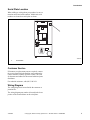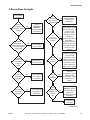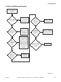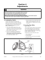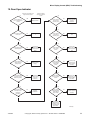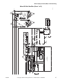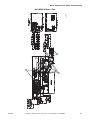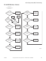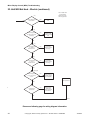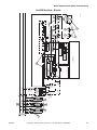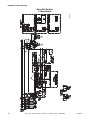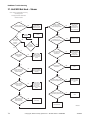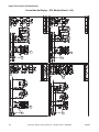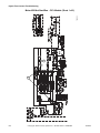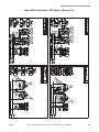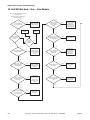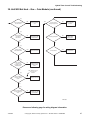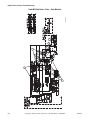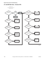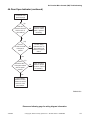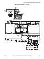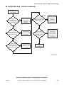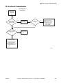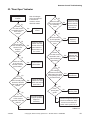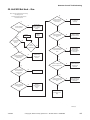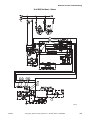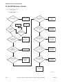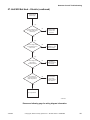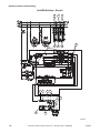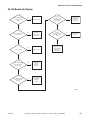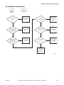
1
Troubleshooting
Drying Tumblers
25 Pound Capacity
30 Pound Capacity
35 Pound Capacity
55 Pound Capacity
Starting Serial No. 0602004144
Refer to Page 7 for Model Numbers
1
SELEC
TEMP T
2
INSER
COIN T
3
PUSH
START
HIGH
TEMP
MED
TEMP
25 C
STAR
T
LOW
TEMP
NO
HEAT
www.comlaundry.com
Part No. 70380601R3
September 2009
Table of
Contents
Section 1 – Safety Information ..........................................................
Locating an Authorized Service Person ...............................................
Safety Warnings and Decals.................................................................
Safety Precautions for Servicing Tumblers ..........................................
4
6
6
6
Section 2 – Introduction ..................................................................... 7
Model Identification ............................................................................. 7
Serial Plate Location............................................................................. 9
Customer Service.................................................................................. 9
Wiring Diagram .................................................................................... 9
How a Tumbler Works ......................................................................... 10
Section 3 – Troubleshooting............................................................... 11
1. Tumbler Does Not Start ........................................................... 12
2. Motor Does Not Start............................................................... 13
3. Motor Overload Protector Cycles Repeatedly ......................... 14
4. Motor Runs But Cylinder Does Not Turn................................ 15
5. Motor Does Not Stop ............................................................... 16
6. Burner Does Not Ignite ............................................................ 17
7. Burner Ignites and Goes Out Repeatedly................................. 20
8. Burner Does Not Shut Off ....................................................... 21
9. Clothes Do Not Dry ................................................................. 22
10. Tumbler Overheating ............................................................... 24
11. Burner Not Burning Properly................................................... 25
12. Loading Door Opens During Operation................................... 26
13. Cylinder Continues to Spin with Door Open ........................... 27
14. Coin Does Not Fall into Coin Vault or Coin Drop Sensor Does Not
Register that Coin Has Been Entered28
Section 4 – Adjustments ..................................................................... 29
15. Loading Door Switch ............................................................... 29
16. Loading Door Strike................................................................. 29
Section 5 – Micro Display Control (MDC) Troubleshooting.......... 30
Models with BC, BL, BX and BY Control Suffixes
17. Coins Ignored When Entered................................................... 30
18. Control Has No Display........................................................... 31
19. Door Open Indicator ................................................................ 33
20. Motor Will Not Start/Run ........................................................ 35
21. Unit Will Not Heat – Gas......................................................... 39
22. Unit Will Not Heat – Steam..................................................... 42
23. Unit Will Not Heat – Electric .................................................. 45
24. Error Codes .............................................................................. 48
Gas and Steam Models
Control Circuit Schematic.................................................................49
Control Circuit Connection ...............................................................50
Gas and Steam Models
Control Box Schematic .....................................................................51
Control Box Connection ...................................................................52
© Copyright 2009, Alliance Laundry Systems LLC
All rights reserved. No part of the contents of this book may be reproduced or transmitted in any form or by any means without
the expressed written consent of the publisher.
70380601
© Copyright, Alliance Laundry Systems LLC – DO NOT COPY or TRANSMIT
1
Gas and Steam Models
Control Circuit Schematic.................................................................53
Gas and Steam Models
Control Circuit Schematic.................................................................54
Gas and Steam Models
Control Box Schematic .....................................................................55
Control Box Connection ...................................................................56
Electric Models
Control Circuit Schematic.................................................................57
Control Circuit Connection ...............................................................58
Electric Models
Control Box Connection ...................................................................59
Control Box Schematic .....................................................................60
Section 6 – NetMaster Troubleshooting ...........................................
Models with NC, NR, NX, NY, ZC, ZR, ZX and ZY
Control Suffixes
25. No Infra-red (IR) Communication ...........................................
26. Coins Ignored When Entered...................................................
27. Control Has No Display...........................................................
28. Door Open Indicator ................................................................
29. Motor Will Not Start/Run ........................................................
30. Unit Will Not Heat – Gas.........................................................
31. Unit Will Not Heat – Steam.....................................................
61
61
62
63
65
67
71
74
Section 7 – Hybrid Timer Control Troubleshooting ....................... 76
Models with QT, SD and SX Control Suffixes
32. Coins Ignored When Entered................................................... 76
33. Control Has No Display – OPL Models .................................. 77
34. Display Flashes “dr” With Door Closed – OPL Models ......... 80
35. Vend Satisfied, No In Use LED – Coin Models ...................... 83
36. In Use LED Lit, No Motor Run – Coin Models ...................... 87
37. Motor Will Not Start/Run – Coin Models ............................... 90
38. Motor Will Not Start/Run – OPL Models................................ 93
39. Unit Will Not Heat – Gas – Coin Models................................ 96
40. Unit Will Not Heat – Gas – OPL Models ................................ 99
41. Unit Will Not Heat – Electric OPL.......................................... 102
42. Error Codes .............................................................................. 106
Section 8 – On Premise Micro Control Troubleshooting................ 107
Models with OM Control Suffix
43. Control Has No Display........................................................... 108
44. Door Open Indicator ................................................................ 110
45. Motor Will Not Start/Run ........................................................ 113
46. Unit Will Not Heat – Gas......................................................... 116
47. Unit Will Not Heat – Steam..................................................... 119
48. Unit Will Not Heat – Electric .................................................. 122
49. Error Codes .............................................................................. 125
2
© Copyright, Alliance Laundry Systems LLC – DO NOT COPY or TRANSMIT
70380601
Section 9 – Quantum Control Troubleshooting............................... 126
Models with LC, LX, LY, WC, WX and WY Control Suffixes
50. No Infrared Communication .................................................... 127
51. Coins Ignored When Entered................................................... 128
52. No Display ............................................................................... 129
53. “Door Open” Indicator............................................................. 131
54. No Start/Run ............................................................................ 133
55. Unit Will Not Heat – Gas......................................................... 135
56. Unit Will Not Heat – Steam..................................................... 138
57. Unit Will Not Heat – Electric .................................................. 140
58. CE Models No Display ............................................................ 143
59. CE Models “Door Open” Indicator.......................................... 145
60. CE Models No Start/Run ......................................................... 147
61. CE Models Will Not Heat – Gas/Steam................................... 149
62. CE Models Will Not Heat – Electric ....................................... 152
70380601
© Copyright, Alliance Laundry Systems LLC – DO NOT COPY or TRANSMIT
3
Section 1
Safety Information
Throughout this manual and on machine decals, you
will find precautionary statements (“CAUTION”,
“WARNING”, and “DANGER”) followed by specific
instructions. These precautions are intended for the
personal safety of the operator, user, servicer, and those
maintaining the machine.
DANGER
Danger indicates an imminently hazardous
situation that, if not avoided, will cause
severe personal injury or death.
WARNING
Warning indicates a hazardous situation
that, if not avoided, could cause severe
personal injury or death.
WARNING
• Failure to install, maintain and/or operate
this product according to the
manufacturer’s instructions may result in
conditions which can produce serious
injury, death and/or property damage.
• Do not repair or replace any part of the
product or attempt any servicing unless
specifically recommended or published
in this Service Manual and unless you
understand and have the skills to carry
out the servicing.
• Whenever ground wires are removed
during servicing, these ground wires
must be reconnected to ensure that the
product is properly grounded and to
reduce the risk of fire, electric shock,
serious injury or death.
W006R2
CAUTION
Caution indicates a hazardous situation
that, if not avoided, may cause minor or
moderate personal injury or property
damage.
Additional precautionary statements (“IMPORTANT”
and “NOTE”) are followed by specific instructions.
IMPORTANT: The word “IMPORTANT” is used
to inform the reader of specific procedures where
minor machine damage will occur if the procedure
is not followed.
NOTE: The word “NOTE” is used to communicate
installation, operation, maintenance or servicing
information that is important but not hazard
related.
In the interest of safety, some general precautions
relating to the operation of this machine follow.
4
© Copyright, Alliance Laundry Systems LLC – DO NOT COPY or TRANSMIT
70380601
Safety Information
IMPORTANT INFORMATION: During the
lifetime of a tumbler, it may require service. The
information contained in this manual was written
and is intended for use by qualified service
technicians who are familiar with the safety
procedures required in the repair of a tumbler, and
who are equipped with the proper tools and testing
equipment.
NOTE: The WARNING and IMPORTANT
instructions appearing in this manual are not meant
to cover all possible conditions and situations that
may occur. It must be understood that common
sense, caution and carefulness are factors which
CANNOT be built into this tumbler. These factors
MUST BE supplied by the person(s) installing,
maintaining or operating the tumbler.
Always contact your dealer, distributor, service agent
or the manufacturer on any problems or conditions you
do not understand.
WARNING
To reduce the risk of electric shock, fire,
explosion, serious injury or death:
• Disconnect electric power to the tumbler
before servicing.
• Never start the tumbler with any guards/
panels removed.
• Whenever ground wires are removed
during servicing, these ground wires
must be reconnected to ensure that the
tumbler is properly grounded.
W240
WARNING
Repairs that are made to your products by
unqualified persons can result in hazards
due to improper assembly or adjustments
subjecting you, or the inexperienced
person making such repairs, to the risk of
serious injury, electrical shock, or death.
W007
CAUTION
If you or an unqualified person perform
service on your product, you must assume
the responsibility for any personal injury or
property damage which may result. The
manufacturer will not be responsible for
any injury or property damage arising from
improper service and/or service
procedures.
W008
70380601
© Copyright, Alliance Laundry Systems LLC – DO NOT COPY or TRANSMIT
5
Safety Information
Locating an Authorized Service
Person
Alliance Laundry Systems is not responsible for
personal injury or property damage resulting from
improper service. Review all service information
before beginning repairs.
Warranty service must be performed by an
authorized technician, using authorized factory
parts. If service is required after the warranty
expires, Alliance Laundry Systems also
recommends contacting an authorized technician
and using authorized factory parts.
Safety Warnings and Decals
SAFETY WARNINGS and decals have been provided
in key locations to remind you of important precautions
for the safe operation and maintenance of your tumbler.
Please take the time to review these warnings before
proceeding with service work.
All decals have been designed and applied to withstand
washing and cleaning. Decals should be checked
periodically to be sure they have not been damaged,
removed, or painted.
6
Safety Precautions for Servicing
Tumblers
Prior to servicing tumbler:
•
Disconnect electrical service and “lockout” to
prevent unintentional connection.
•
Shut off supply gas valve.
•
Allow machine to cool prior to servicing.
After servicing tumbler:
•
Control/access panels must be reinstalled.
•
Motor/drive/belt guards must be reinstalled.
•
Contactor/junction/accessory box covers must
be reinstalled.
•
Use a non-corrosive leak detection solution to
check all pipe connections for gas leaks. DO
NOT USE AN OPEN FLAME TO CHECK
FOR GAS LEAKS!
•
The loading door switch, lint door switch and
airflow switch must be operating properly.
© Copyright, Alliance Laundry Systems LLC – DO NOT COPY or TRANSMIT
70380601
Section 2
Introduction
Model Identification
Information in this manual is applicable to these models:
Gas
Steam
Electric
25
Pound
CHD25G2-CA025L
CHD25G2-CA025N
CHD25G2-CT025L
CHD25G2-CT025N
CHD25G2-CU025L
CHD25G2-CU025N
DR25G2-BA025L
DR25G2-BA025N
DR25G2-BT025L
DR25G2-BT025N
DR25G2-BU025L
DR25G2-BU025N
GA025L
GA025N
GT025L
GT025N
GU025L
GU025N
HA025L
HA025N
HT025L
HT025N
HU025L
HU025N
IPD25G2-IT025L
IPD25G2-IT025N
KA025L
KA025N
KT025L
KT025N
KU025L
KU025N
LA025L
LA025N
LT025L
LT025N
LU025L
LU025N
PA025L
PA025N
PT025L
PT025N
PU025L
PU025N
SA025L
SA025N
ST025L
ST025N
SU025L
SU025N
UA025L
UA025N
UT025L
UT025N
UU025L
UU025N
YT025L
YT025N
CHD25S2-CT025S
CHD25S2-CU025S
DR25S2-BT025S
DR25S2-BU025S
GT025S
GU025S
HT025S
HU025S
IPD25S2-IT025S
KT025S
KU025S
LT025S
LU025S
PT025S
PU025S
ST025S
SU025S
UT025S
UU025S
YT025S
CHD25E2-CT025E
CHD25E2-CU025E
DR25E2-BT025E
DR25E2-BU025E
GT025E
GU025E
HT025E
HU025E
IPD25E2-IT025E
KT025E
KU025E
LT025E
LU025E
PT025E
PU025E
ST025E
SU025E
UT025E
UU025E
YT025E
30
Pound
CHD30G2-CA030L
CHD30G2-CA030N
CHD30G2-CT030L
CHD30G2-CT030N
CHD30G2-CU030L
CHD30G2-CU030N
DR30G2-BA030L
DR30G2-BA030N
DR30G2-BT030D
DR30G2-BT030L
DR30G2-BT030N
DR30G2-BU030L
DR30G2-BU030N
GA030L
GA030N
GT030L
GT030N
GU030L
GU030N
HA030L
HA030N
HT030D
HT030L
HT030N
HU030L
HU030N
IPD30G2-IT030L
IPD30G2-IT030N
KT030L
KT030N
LA030L
LA030N
LT030L
LT030N
LU030L
LU030N
PA030L
PA030N
PT030L
PT030N
PU030L
PU030N
SA030L
SA030N
ST030D
ST030L
ST030N
SU030L
SU030N
UA030L
UA030N
UT030L
UT030N
UU030L
UU030N
YT030L
YT030N
CHD30S2-CT030S
CHD30S2-CU030S
DR30S2-BT030S
DR30S2-BU030S
GT030S
GU030S
HT030S
HU030S
IPD30S2-IT030S
KT030S
LT030S
LU030S
PT030S
PU030S
ST030S
SU030S
UT030S
UU030S
YT030S
CHD30E2-CT030E
CHD30E2-CU030E
DR30E2-BT030E
DR30E2-BU030E
GT030E
GU030E
HT030E
HU030E
IPD30E2-IT030E
KT030E
LT030E
LU030E
PT030E
PU030E
ST030E
SU030E
UT030E
UU030E
YT030E
Models continued on next page.
70380601
© Copyright, Alliance Laundry Systems LLC – DO NOT COPY or TRANSMIT
7
Introduction
Gas
35
Pound
55
Pound
Steam
AT035L
AT035N
CHD35G2-CA035L
CHD35G2-CA035N
CHD35G2-CT035L
CHD35G2-CT035N
CHD35G2-CU035L
CHD35G2-CU035N
DR35G2-BA035L
DR35G2-BA035N
DR35G2-BT035L
DR35G2-BT035N
DR35G2-BU035L
DR35G2-BU035N
GA035L
GA035N
GT035L
GT035N
GU035L
GU035N
HA035L
HA035N
HT035L
HT035N
HU035L
HU035N
IPD35G2-IT035L
IPD35G2-IT035N
KA035L
KA035N
KT035L
KT035N
KU035L
KU035N
LA035L
LA035N
LT035L
LT035N
LU035L
LU035N
PA035L
PA035N
PT035L
PT035N
PU035L
PU035N
SA035L
SA035N
ST035L
ST035N
SU035L
SU035N
UA035L
UA035N
UT035L
UT035N
UU035L
UU035N
YT035L
YT035N
CA055L
CA055N
CT055L
CT055N
CU055L
CU055N
GT055L
GT055N
HA055L
HA055N
HT055D
HT055L
HT055N
HU055L
HU055N
IPD55G2-IT055L
IPD55G2-IT055N
KT055L
KT055N
SA055L
SA055N
ST055D
ST055L
ST055N
SU055L
SU055N
UA055L
UA055N
UT055L
UT055N
UU055L
UU055N
AT035S
CHD35S2-CT035S
CHD35S2-CU035S
DR35S2-BT035S
DR35S2-BU035S
GT035S
GU035S
HT035S
HU035S
IPD35S2-IT035S
KT035S
KU035S
LT035S
LU035S
PT035S
PU035S
ST035S
SU035S
UT035S
UU035S
YT035S
YU035S
Not
Applicable
Electric
AT035E
CHD35E2-CT035E
CHD35E2-CU035E
DR35E2-BT035E
DR35E2-BU035E
GT035E
GU035E
HT035E
HU035E
IPD35E2-IT035E
KT035E
KU035E
LT035E
LU035E
PT035E
PU035E
ST035E
SU035E
UT035E
UU035E
YT035E
YU035E
CT055E
CU055E
GT055E
HT055E
HU055E
IPD55E2-IT055E
KT055E
ST055E
SU055E
UT055E
UU055E
Includes models with the following control suffixes:
3O – DX4 OPL
3V – DX4 vended
3X – DX4 prep for coin
BC – basic electronic, coin
BL – basic electronic, central pay
BX – basic electronic, prep for coin
BY – basic electronic, prep for card
DO – DMP OPL
DV – DMP vended
DX – DMP prep for coin
8
LC – network adaptable coin
LX – network adaptable, prep for coin
LY – network adaptable, prep for card
NC – NetMaster coin
NR – NetMaster card
NX – NetMaster, prep for coin
NY – NetMaster, prep for card
OM – OPL micro
QT – dual digital timer
SD – single drop
SX – single drop, prep for coin
WC – network ready coin
WX – network ready, prep for coin
WY – network ready, prep for card
ZC – NetMaster network coin
ZR – NetMaster network card
ZX – NetMaster network, prep for coin
ZY – NetMaster network, prep for card
© Copyright, Alliance Laundry Systems LLC – DO NOT COPY or TRANSMIT
70380601
Introduction
Serial Plate Location
When calling or writing about your product, be sure to
mention model and serial numbers. Model and serial
numbers are located on serial plate as shown.
1
TMB2098N
1
Serial Plate
Customer Service
If literature or replacement parts are required, contact
the source from which the machine was purchased or
contact Alliance Laundry Systems at (920) 748-3950
for the name and address of the nearest authorized parts
distributor.
For technical assistance, call (920) 748-3121.
Wiring Diagram
The wiring diagram is located inside the contactor or
junction box.
The wiring diagram part number is located in the lower
portion of the electrical data on the serial plate.
70380601
© Copyright, Alliance Laundry Systems LLC – DO NOT COPY or TRANSMIT
9
Introduction
How a Tumbler Works
A tumbler uses heated air to dry loads of laundry.
1
When the motor is started, the exhaust fan pulls
room temperature air in through the air intake at
the rear of the tumbler and over the heat source
(burner flame for gas, heating element for
electric, and coil for steam).
2
The heated air moves into the cylinder, where it is
circulated through the wet load by the tumbling
action of the cylinder.
3
The air then passes through the lint filter, exhaust
fan, and is vented to the outdoors.
1
2
3
T001CE3A
10
© Copyright, Alliance Laundry Systems LLC – DO NOT COPY or TRANSMIT
70380601
Section 3
Troubleshooting
WARNING
To reduce the risk of electric shock, fire, explosion, serious injury or death:
• Disconnect electric power to the tumbler before servicing.
• Close gas shut-off valve to gas tumbler before servicing.
• Close steam valve to steam tumbler before servicing.
• Never start the tumbler with any guards/panels removed.
• Whenever ground wires are removed during servicing, these ground wires must be
reconnected to ensure that the tumbler is properly grounded.
W002
IMPORTANT: Refer to wiring diagram for aid in
testing tumbler components.
70380601
© Copyright, Alliance Laundry Systems LLC – DO NOT COPY or TRANSMIT
11
Troubleshooting
1. Tumbler Does Not Start
Tumbler Does
Not Start
Is motor
relay
inoperative?
Yes
Test relay and
replace if
necessary.
No
Is
loading door
open?
Close loading
door
completely.
Yes
No
Is
drying timer in
an off position
(Hybrid Timer
Models)?
Yes
Turn drying
timer on.
Check that
proper amount
of coins are
inserted.
Is coin drop
inoperative?
Yes
Check power
supply, or
replace fuses.
Yes
Close and
lock lint
panel.
No
Is there a
blown fuse
on tumbler?
No
Yes
No
Is the lint
panel
open?
Yes
Yes
Press and
hold
START button
for three
seconds.
No
Is the
electrical power
off or circuit
breaker or fuse
blown?
No
Is there an
incorrect
amount of coins
inserted into
coin drop?
Is the
START button
not properly
activated
(Hybrid Timer
Models)?
Yes
Check fuse
(in junction box)
and replace if
necessary.
Test coin drop
and replace if
inoperative.
No
TMB2036S
12
© Copyright, Alliance Laundry Systems LLC – DO NOT COPY or TRANSMIT
70380601
Troubleshooting
2. Motor Does Not Start
Motor Does
Not Start
Is the
electrical power
off or circuit
breaker fuse
blown?
Is there
broken, loose,
or incorrect
wiring?
Yes
Refer to wiring
diagram.
No
Yes
Check power
supply, or replace
fuses.
Is
the fan or fan
motor
binding?
Yes
Replace fan or
motor assembly.
No
No
Is the
loading door
switch or lint
panel switch not
closed or switch
inoperative?
Yes
Close door, panel
or test switch and
replace if
inoperative.
No
Is the
door switch
improperly
adjusted?
Replace cylinder,
bearing, rollers, or
motor assembly.
Yes
No
Yes
Refer to
Adjustments
Section for door
switch adjustment.
Is the
transformer
inoperative?
Yes
Test and replace
if necessary.
Yes
Test relay and replace
if inoperative.
No
No
Is the start
circuit not
complete?
Is the
cylinder or
cylinder motor
binding?
Yes
Press and hold
START button for
three seconds.
Is the
motor relay
inoperative?
No
No
Is the motor
inoperative?
Yes
Have motor tested
and replace if
inoperative.
Is the
airflow switch
inoperative
(Hyrid Timer
Models)?
Yes
Test switch,
replace or adjust
as required.
No
TMB2037S
70380601
© Copyright, Alliance Laundry Systems LLC – DO NOT COPY or TRANSMIT
13
Troubleshooting
3. Motor Overload Protector Cycles Repeatedly
Motor Overload
Protector
Cycles
Repeatedly
Yes
Is voltage
correct?
No
Is clothes
load too
large?
Yes
Refer to
Installation
Manual for
electrical
requirements.
Remove part of
load.
No
Is clothes
cylinder
binding?
Yes
Check cylinder
for binding.
No
Check with
local power
company to
ensure that
wiring is
adequate.
Yes
Is wiring
adequate?
No
Yes
Is make-up
air adequate?
Refer to
Installation
Manual for
make-up air
requirements.
No
Is there lint
buildup around
tumbler or poor
maintenance?
No
Clean lint
accumulation
on and around
the motors.
Yes
Is there
broken, loose
or incorrect
wiring?
Yes
Refer to wiring
diagram.
TMB1904S
14
© Copyright, Alliance Laundry Systems LLC – DO NOT COPY or TRANSMIT
70380601
Troubleshooting
4. Motor Runs But Cylinder Does Not Turn
Motor Runs
But Cylinder
Does Not Turn
Is cylinder
belt
broken?
Yes
Replace
cylinder belt.
Yes
Check cylinder
for binding.
No
Is cylinder
binding?
TMB1905S
70380601
© Copyright, Alliance Laundry Systems LLC – DO NOT COPY or TRANSMIT
15
Troubleshooting
5. Motor Does Not Stop
Motor Does
Not Stop
Is the door
switch or lint
panel switch
not working
properly?
Yes
Test switches
and replace if
inoperative.
No
Is coin drop
not working
properly?
Yes
Test coin drop
and replace if
inoperative.
No
Is wiring
incorrect?
Yes
Refer to wiring
diagram.
No
Is electronic
control
inoperative?
Yes
Replace
electronic
control.
Yes
Test relay and
replace if
inoperative.
No
Is motor
relay
inoperative?
TMB2038S
16
© Copyright, Alliance Laundry Systems LLC – DO NOT COPY or TRANSMIT
70380601
Troubleshooting
6. Burner Does Not Ignite
Burner Does
Not Ignite
Is there
an improper or
inadequate exhaust
system?
Is
stove limit
thermostat 2
inoperative?
Yes
Refer to
Installation
Manual for
exhaust system
requirements.
Is
there an
insufficient gas
supply?
No
Are there
blown fuses or
Yes
tripped circuit breakers
in external electric
supply line?
No
Check fuses or
circuit breaker.
No
No
Is
drying
selector in the
“Cool Down”
portion of
cycle?
Yes
Reset switch on
microprocessor.
Are the
orifices
incorrect?
No
Yes
Test thermostat 2
and replace if
inoperative.
Open partially closed
gas shut-off valve, or
correct low gas
pressure. Check
manifold pressure
and adjust to
Yes
pressure specified on
serial plate. If
pressure cannot be
obtained, have your
local gas company
check main gas
pressure.
Tumbler is equipped
for type of gas
specified on serial
Yes
plate. If orifices are
different from that
specified on serial
plate, obtain and
install correct orifices.
No
Is
the cabinet
thermostat
inoperative?
Yes
Test thermostat
and replace if
inoperative.
Is there
lint
buildup?
Yes
No
Clean lint
compartment. Check
damper for lint
accumulation. Check
ductwork for lint
buildup.
No
Is
stove limit
thermostat 1
inoperative?
Yes
Test thermostat 1
and replace if
inoperative.
Is there
inadequate
ductwork and
make-up
air?
Yes
Refer to Installation
Manual to ensure
that ductwork and
make-up air
openings are sized
accurately.
No
No
Continued on
next page
TMB2187S-a
70380601
© Copyright, Alliance Laundry Systems LLC – DO NOT COPY or TRANSMIT
17
Troubleshooting
6. Burner Does Not Ignite (continued)
Continued from
previous page
Is the
airflow switch
inoperative?
Is
there a blown
fuse on
tumbler?
Yes
Test switch
and replace
if inoperative.
No
Is the lint
panel not
closed
properly?
Yes
Unlock and open
lint panel. Close
panel ensuring a
tight fit, then lock.
No
Is
there broken,
loose or incorrect
wiring?
Yes
Refer
to wiring
diagram.
Check fuse
(located in
control box)
and replace if
necessary.
Yes
No
Is
gas shut-off
valve in the
closed
position?
Yes
Open shutoff valve.
No
Is the
ground wire
from Instant
Electronic Ignition
(IEI) board not
connected to
ground
terminal?
Yes
Connect
ground wire
to ground
terminal.
No
No
Is
there an
improper igniter
to burner
clearance?
Yes
Clearance
should be
0.110 - 0.140
inch (2.79 - 3.55
mm).
No
Yes
Check valve
coils and
replace if
necessary.
Yes
Replace IEI
control.
No
Is
motor switch
inoperative?
No
Are valve coils
inoperative?
Is the
IEI control
inoperative?
Yes
Replace motor.
No
Continued on
next page
TMB2187S-b
18
© Copyright, Alliance Laundry Systems LLC – DO NOT COPY or TRANSMIT
70380601
Troubleshooting
6. Burner Does Not Ignite (continued)
Continued from
previous page
Is there
an inoperative
microprocessor or
hybrid timer?
Yes
Test and replace
as needed.
No
Is
wrong
transformer
configuration
harness
installed?
Yes
Check incoming
voltage and install
correct
configuration
harness.
No
Is Instant
Electronic
Ignition (IEI)
control in safety
lockout?
Yes
Reset IEI control by
opening and closing
loading door. (NonCE models only)
Reset IEI by
pressing reset
button on back of
unit. (CE models
only)
TMB2187S-c
70380601
© Copyright, Alliance Laundry Systems LLC – DO NOT COPY or TRANSMIT
19
Troubleshooting
7. Burner Ignites and Goes Out Repeatedly
Burner Ignites
and Goes Out
Repeatedly
Is
Yes
there excessive
igniter to burner
clearance?
Is there
insufficient
gas
pressure?
Yes
Check gas
supply and
pressure.
Is the
cabinet
thermostat
inoperative?
Yes
Test thermostat
and replace if
inoperative.
No
Is the
exhaust system
improper or
inadequate?
No
Does
tumbler have
improper
orifices?
No
Is there
broken, loose
or incorrect
wiring?
No
Is
there inadequate
make-up air?
No
Yes
Refer to
Installation
Manual for
exhaust
system
requirements.
Tumbler is equipped
for type of gas
specified on serial
Yes plate. If orifices are
different from that
specified on serial
plate, obtain and
install correct
orifices.
Yes
Refer to wiring
diagram.
Refer to
Paragraph 43.
Refer to
Installation
Manual for
make-up air
requirements.
Yes
No
Is the
thermistor
inoperative?
Yes
Replace
thermistor.
No
Is the control
heater relay
malfunctioning?
Yes
Replace control.
No
Are the back
draft dampers
locked in close
position?
Yes
Repair damper to
working order.
No
20
TMB1908S
© Copyright, Alliance Laundry Systems LLC – DO NOT COPY or TRANSMIT
70380601
Troubleshooting
8. Burner Does Not Shut Off
Burner Does
Not Shut Off
Are there
impurities on gas
valve seat,
preventing valve
from closing?
Yes
Replace gas
valve.
No
Is wiring
correct?
Yes
Refer to wiring
diagram.
No
Is control heater
relay
malfunctioning?
Yes
Replace
control.
TMB1909S
70380601
© Copyright, Alliance Laundry Systems LLC – DO NOT COPY or TRANSMIT
21
Troubleshooting
9. Clothes Do Not Dry
Clothes Do Not
Dry
Is there
enough heating
time allocated for
the load?
Yes
Start cycle again
with enough time to
dry load.
Does
the burner ignite
and go out
repeatedly?
Refer to
Paragraph 7.
Yes
No
No
Is the burner not
igniting?
Yes
Refer to
Paragraph 6.
Is
the drying
selector
improperly
set?
Set selector
for higher
setting.
Yes
No
No
Is there
too much water in
articles being
dried?
Is
the voltage
incorrect?
Yes
Remove excess
water.
No
Is
the clothes
load too
large?
Yes
Remove part of
load. Maximum
load is 25 pound
dry weight (cotton
load) for 25 pound
Tumbler, etc.
No
Is the
exhaust system
improper or
inadequate?
Yes
Refer to Installation
Manual for exhaust
system
requirements.
Yes
Refer to Installation
Manual for electrical
requirements.
No
Is there
inadequate
make-up
air?
Yes
Refer to Installation
Manual for make-up
air requirements.
No
Is the
exhaust duct to
the outside
blocked?
Yes
Clean duct to
remove blockage.
No
Continued on
next page
No
TMB1910S-a
22
© Copyright, Alliance Laundry Systems LLC – DO NOT COPY or TRANSMIT
70380601
Troubleshooting
9. Clothes Do Not Dry (continued)
Continued from
previous page
Is the lint screen
clogged?
Yes
Clean lint screen.
Yes
Adjust damper so it
turns freely.
No
No
Is the thermistor
inoperative?
Is the
exhaust
damper
binding?
Yes
Replace thermistor.
Is the
cylinder speed
too fast?
Yes
Check belt is not
riding on outer
diameter of motor
pulley.
No
No
Is airflow switch
bracket mounted
properly?
Yes
Check for proper
alignment: make
sure locator pins
are securely in
place and tighten
mounting screws.
TMB1910S-b
70380601
© Copyright, Alliance Laundry Systems LLC – DO NOT COPY or TRANSMIT
23
Troubleshooting
10. Tumbler Overheating
Tumbler
Overheating
Does
tumbler
have incorrect
main burner
orifices?
Is the
thermistor
sensor
inoperative?
Yes
Obtain and install
correct orifices.
No
Is the
exhaust
damper
binding?
No
Is gas
Yes
pressure too high or
low?
Adjust gas pressure
as specified on
serial plate.
Yes
Refer to Installation
Manual for make-up
air requirements.
No
Is there
lint buildup?
Yes
Clean lint
compartment. Check
damper for lint
accumulation. Check
ductwork for lint
buildup.
No
Is the
exhaust system
restricted or
inadequate?
No
Yes
Remove obstruction
or lint build up from
exhaust ductwork.
Refer to Installation
Manual for exhaust
system
requirements.
Yes
Adjust damper
so it turns
freely.
No
Is the
control heater
relay
malfunctioning?
No
Is the
make-up air
inadequate?
Yes
Check wiring to
ensure thermistor
is connected.
Replace
thermistor if
necessary.
Remove lint buildup on thermistor.
Yes
Replace control.
No
Are
the safety covers
missing, allowing
cool air to enter
tumbler?
Yes
Replace covers.
No
Is the
lint screen
clogged with
fabric
softener?
Yes
Replace lint
screen.
No
Are there
holes in cabinets
due to foreign
objects?
Yes
Repair/replace
cabinet
components.
TMB1911S
24
© Copyright, Alliance Laundry Systems LLC – DO NOT COPY or TRANSMIT
70380601
Troubleshooting
11. Burner Not Burning Properly
Burner Not Burning
Properly
Is there lint/dirt in
burner tube?
Yes
Disassemble
burner and
blow out the dirt.
No
No
Yes
No
Is the
exhaust duct
restricted or
blocked?
Yes
Replace airflow
switch.
No
Is the gas
Yes
pressure too high
or low?
Does
the tumbler have
incorrect
orifices?
Is
the airflow
switch not
functioning
properly?
Yes
Check serial
plate on back of
tumbler for
correct gas
pressure.
Tumbler is equipped
for the type of gas
specified on serial
plate. If orifices are
different from that
specified on serial
plate, obtain and
install correct
orifices.
Is there
inadequate
make-up
air?
Yes
Refer to Installation
Manual for make-up
air requirements.
No
Is there lint buildup
around gas valve
spud?
Yes
Clean off lint.
Disassemble
and clean
exhaust system.
No
TMB1912S
70380601
© Copyright, Alliance Laundry Systems LLC – DO NOT COPY or TRANSMIT
25
Troubleshooting
12. Loading Door Opens During Operation
Loading Door
Opens During
Operation
Is tumbler
improperly
leveled?
Yes
Refer to Installation
Manual for leveling
leg adjustment.
Yes
Remove part of load
and restart tumbler.
No
Is clothes
load too
large?
No
Is loading
door strike
adjusted
incorrectly?
Yes
Refer to
Adjustments
Section for strike
adjustment.
TMB1913S
26
© Copyright, Alliance Laundry Systems LLC – DO NOT COPY or TRANSMIT
70380601
Troubleshooting
13. Cylinder Continues to Spin with Door Open
Cylinder
Continues To
Spin With Door
Open
Is relay
inoperative?
Yes
Replace relay
in control box.
TMB1914S
NOTE: All tumbler panels must be in place and on the machine for
proper operation.
70380601
© Copyright, Alliance Laundry Systems LLC – DO NOT COPY or TRANSMIT
27
Troubleshooting
14. Coin Does Not Fall into Coin Vault or Coin Drop Sensor Does Not Register
that Coin Has Been Entered
Coin Does Not Fall
Into Coin Vault or Coin
Drop Sensor Does Not
Register That Coin
Has Been Entered
Is proper
electrical
power
supplied to
coin drop?
No
Yes
Is
machine
level?
No
Incorrect electrical
connection may
prevent coins from
registering in coin drop.
Refer to wiring
diagram.
Machines that are not
level may prevent coins
from following through
required check stages
of drop. Refer to
Installation Manual
for instructions on
leveling machine.
Yes
Is coin
drop
clean?
No
Residue or lint build-up
may prevent coins from
following through
required check stages
of drop. Clean coin
drop.
Yes
Is sensor
operative?
No
Replace coin drop
sensor.
TMB1915S
IMPORTANT: Never use oil to correct coin drop problem. Oil residue will prevent coins from rolling
properly.
IMPORTANT: Do not bend or damage mechanical parts within coin drop.
28
© Copyright, Alliance Laundry Systems LLC – DO NOT COPY or TRANSMIT
70380601
Section 4
Adjustments
WARNING
To reduce the risk of electric shock, fire, explosion, serious injury or death:
• Disconnect electric power to the tumbler before servicing.
• Close gas shut-off valve to gas tumbler before servicing.
• Close steam valve to steam tumbler before servicing.
• Never start the tumbler with any guards/panels removed.
• Whenever ground wires are removed during servicing, these ground wires must be
reconnected to ensure that the tumbler is properly grounded.
W002
15. Loading Door Switch
The door switch should be adjusted so the
cylinder stops when door is opened 2 inches (51
mm), plus or minus 1/4 inch (6 mm). The switch
is normally open and is closed when the door is
closed. If adjustment is needed, proceed as
follows: Refer to Figure 1.
c. If switch actuator does not depress the switch
plunger enough to operate the switch, bend
switch actuator OUTWARD and repeat steps
“a” and “b.”.
16. Loading Door Strike
a. Close door and start tumbler. Slowly open
loading door. Cylinder and heat system should
shut off when door is open 2 inches (51 mm),
plus or minus 1/4 inch (6 mm).
b. Slowly close loading door. When door is 2
inches or less from being fully closed, the
switch actuator on the door should contact the
switch plunger and depress it enough to close
the switch with an audible “click”.
Refer to Figure 1.
The door strike must be adjusted so that sufficient
tension holds loading door closed against the
force of a load tumbling against it. The door is
properly adjusted when 8-15 lbs. (3.60-6.75 kg)
of pull is required to open door.
If adjustment is needed, follow these steps:
a.
b.
c.
d.
Open loading door.
Loosen jamnut.
Turn door strike screw in or out as required.
Retighten jamnut.
Loading
Door
Switch
Actuator
Jamnut
Door Strike
Screw
T280SE3C
Figure 1
70380601
© Copyright, Alliance Laundry Systems LLC – DO NOT COPY or TRANSMIT
29
Section 5
Micro Display Control (MDC)
Troubleshooting
Models with BC, BL, BX and BY Control Suffixes
WARNING
To reduce the risk of electric shock, fire, explosion, serious injury or death:
• Disconnect electric power to the tumbler before servicing.
• Close gas shut-off valve to gas tumbler before servicing.
• Close steam valve to steam tumbler before servicing.
• Never start the tumbler with any guards/panels removed.
• Whenever ground wires are removed during servicing, these ground wires must be
reconnected to ensure that the tumbler is properly grounded.
W002
17. Coins Ignored When Entered
Gas and electric heat.
Single and three phase
power supply.
Start coin drop
diagnostic tests.
Does the display on the
electronic control
increment properly?
YES
Exit diagnostic
testing and reset
control. (Prompting
for vend price)
NO
Reconnect and run
diagnostic test
again.
NO
Reconnect and run
diagnostic test
again.
NO
Is connector H2 on the
control firmly seated in
its receptacle?
YES
Is the 3 pin connector
between coin drop and
control connected
correctly?
YES
Are wires exiting coin
drop optical sensor
cracked or broken?
YES
Replace coin drop
or optic switch.
NO
Replace coin drop.
If problem still exists
then replace the
electronic control.
30
TMB1978S
© Copyright, Alliance Laundry Systems LLC – DO NOT COPY or TRANSMIT
70380601
Micro Display Control (MDC) Troubleshooting
18. Control Has No Display
Control has no display
(1)
Is there voltage across
H1-1 & H1-3 on
the control?
Gas, steam and electric heat.
Single and three phase power supply.
(6)
YES
Replace electronic
control.
NO
Is there voltage at
the input of the
secondary fuse?
NO
Correct wiring
between secondary
fuse and
transformer.
YES
(7)
Is there power supplied
to the unit?
NO
Plug unit in and run
it.
YES
Is there voltage at
output side of
secondary fuse?
NO
Replace secondary
fuse.
YES
(2)
Is there voltage at input
of primary fuses?
NO
Correct wiring
between primary
fuse and power
supply.
Correct wiring
between control and
secondary fuse.
YES
(3)
Is there voltage at
output side of the
primary fuses?
NO
Replace primary
fuse(s).
YES
(4)
Is there voltage across
terminals 1 & 2 of
transformer primary?
NO
Correct wiring
between primary
fuse and
transformer.
YES
(5)
Is there voltage across
terminals 1 &
4 of transformer
secondary?
NO
Replace
transformer.
YES
TMB1979S
70380601
© Copyright, Alliance Laundry Systems LLC – DO NOT COPY or TRANSMIT
31
L2
4
7
SECONDARY
FUSE
MDL-3.5A
250V
6
2
BLK
BLK
RED
RED
RED/WHT
120V
1
N.O.
COM
LT. BLU
4
2
3
RED/WHT
RED/BLU
5
N.O.
COM
LINT
PANEL
SWITCH
SECONDARY
FUSE
1.25 T
250V
WHT
24V
1.5A
DOOR
SWITCH
3
24V
3.5A
1
250V
AGC-2A
FUSE
PRIMARY
2
RED
RED
N
RED/BLK
RED/BLK
RED/BLK
FS-2
H2-1
H2-2
H2-5
3
MDC CONTROL
2
1
5
H5
6 8
7
9
10 11 12
HEAT RELAY
MOTOR RELAY
COIN DROPS
4
RED
WHT/BLU
DOOR SENSING CIRCUIT ALLOWS
CONTROL TO TURN ON MOTOR
RELAY ONLY WHEN DOOR IS
CLOSED & SWITCH IS PRESSED
VOLTAGE CONFIGURATION INPUT
JUMPER H2-2 TO H2-5 AS FOLLOWS:
24Vac - WIRE JUMPER
120Vac - 6.8K ohm 5 watt
240Vac - 13.6K ohm 10 watt
24Vac
H1-2
© Copyright, Alliance Laundry Systems LLC – DO NOT COPY or TRANSMIT
2
H6
3 4
5
6
SEE VEND
APPLICATION DETAIL
1
24VAC
H4
10 9
7
6
H3
5
4
7
6
5
4
3
3
2
2
100 OHM
1/4 watt
1
Door Sense Ret
TEMP. REGULATING
CIRCUIT CONTROLS
HEAT RELAY
8
WHT
FS-1
H2-4
H2-3
H2-6
1
WHT
H4
10 9
COM
AIR FLOW
SWITCH
ORG/BRN
WHT
8
CABINET
LIMIT
THERMOSTAT
N.O.
N.C.
7
WHT
6
5
WHT
4
3
2
1
WHT
TMB2213S
BLK
THERMISTOR
035 & 055 MODELS
BRN/RED
CHASSIS GROUND
GRN/YEL
BLK
THERMISTOR
025 & 030 MODELS
START PULSE INPUT
H3-1 & H3-2
Iin= 3-30ma
TIME 20msec MIN.
AVAILABLE OUTPUT
H3-3 & H3-4
OPTO OFF WHEN
MACHINE RUNNING
Vmax=28Vdc
Imax=5ma
CONTROL
POWER
SUPPLY
1
H1-1
CONNECTION
24Vac Ret
H1-4
H1-3
24Vac Ret
SERVICE
4N25
L1
H11L1
32
WHT/VLT
TB1
Micro Display Control (MDC) Troubleshooting
Control Has No Display
70380601
Micro Display Control (MDC) Troubleshooting
19. Door Open Indicator
Gas, steam and electric heat.
Single and three phase
(1)
Is there voltage at
H2-1 on the Electronic
control?
Reference voltage
checks to transformer
neutral.
YES
Replace Control.
NO
(6)
Is there voltage at
the input of the
secondary fuse?
NO
Correct wiring
between secondary
fuse and
transformer.
YES
(7)
Is there power supplied
to the unit?
NO
Plug unit in and run
it.
YES
NO
Correct wiring
between primary
fuses and power
supply.
NO
Replace primary
fuse(s).
Correct wiring
between N.O. and
output of secondary
fuse.
With door closed is
there voltage to
COM of door
switch?
NO
Check for proper
function of door
switch replace if
necessary.
NO
Correct wiring
between N.O. on lint
panel and COM on
door switch.
NO
Check for proper
operation replace if
necessary.
YES
(4)
(10)
NO
Correct wiring
between primary
fuses and
transformer.
YES
Is there voltage at
N.O. of lint panel
switch?
YES
(5)
YES
NO
(9)
YES
Is there voltage across
terminals 2 & 3 of
transformer
secondary?
Is there voltage at
N.O. of door
switch?
YES
(3)
Is there voltage across
terminals 1 & 2 of
transformer primary?
Replace secondary
fuse.
(8)
YES
Is there voltage at
output side of the
primary fuses?
NO
YES
(2)
Is there voltage at input
of primary fuses?
Is there voltage at
output side of
secondary fuse?
(11)
NO
Replace
transformer.
Is there voltage at
COM of lint panel
switch with lint
panel closed?
YES
Correct wiring
between H2-1 of
electronic control
and COM of lint
panel switch.
TMB2039S
70380601
© Copyright, Alliance Laundry Systems LLC – DO NOT COPY or TRANSMIT
33
7
L2
SECONDARY
FUSE
MDL-3.5A
250V
6
2
BLK
BLK
RED
RED
RED/WHT
FUSE
9
1
N.O.
COM
LT. BLU
4
2
4
RED/WHT
N.O.
COM
LINT
PANEL
SWITCH
11
RED/BLU
10
SECONDARY
FUSE
1.25 T
250V
WHT
24V
1.5A
DOOR
SWITCH
8
3
120V
250V
AGC-2A
24V
3.5A
1
3
PRIMARY
2
RED
RED
N
RED/BLK
RED/BLK
RED/BLK
5
FS-2
H2-1
H2-2
H2-5
3
2
1
5
H5
6 8
7
9
10 11 12
HEAT RELAY
MOTOR RELAY
COIN DROPS
4
RED
WHT/BLU
DOOR SENSING CIRCUIT ALLOWS
CONTROL TO TURN ON MOTOR
RELAY ONLY WHEN DOOR IS
CLOSED & SWITCH IS PRESSED
VOLTAGE CONFIGURATION INPUT
JUMPER H2-2 TO H2-5 AS FOLLOWS:
24Vac - WIRE JUMPER
120Vac - 6.8K ohm 5 watt
240Vac - 13.6K ohm 10 watt
MDC CONTROL
24Vac
H1-2
© Copyright, Alliance Laundry Systems LLC – DO NOT COPY or TRANSMIT
2
H6
3 4
5
6
SEE VEND
APPLICATION DETAIL
1
24VAC
H4
10 9
7
6
H3
5
4
7
6
5
4
3
3
2
2
100 OHM
1/4 watt
1
Door Sense Ret
TEMP. REGULATING
CIRCUIT CONTROLS
HEAT RELAY
8
WHT
FS-1
H2-4
H2-3
H2-6
1
WHT
H4
10 9
COM
AIR FLOW
SWITCH
ORG/BRN
WHT
CABINET
LIMIT
THERMOSTAT
N.O.
N.C.
BRN/RED
8
7
WHT
6
5
WHT
4
3
035 & 055 MODELS
CHASSIS GROUND
GRN/YEL
BLK
THERMISTOR
025 & 030 MODELS
START PULSE INPUT
H3-1 & H3-2
Iin= 3-30ma
TIME 20msec MIN.
AVAILABLE OUTPUT
H3-3 & H3-4
OPTO OFF WHEN
MACHINE RUNNING
Vmax=28Vdc
Imax=5ma
CONTROL
POWER
SUPPLY
1
H1-1
CONNECTION
24Vac Ret
H1-4
H1-3
24Vac Ret
L1
4N25
SERVICE
H11L1
34
WHT/VLT
TB1
2
1
TMB2214S
BLK
THERMISTOR
WHT
Micro Display Control (MDC) Troubleshooting
Door Open Indicator
70380601
Micro Display Control (MDC) Troubleshooting
20. Motor Will Not Start/Run
Note: test conducted with vend
(1) price satisfied and start button
pressed.
NO
Is there voltage across
H2-1 and H2-6 on
the electronic control ?
Gas, electric and steam heat.
Single and three phase power supply.
Refer to Door
Open Indicator
flowchart.
Replace MDC
control.
(6)
Is there voltage across
terminals 1 & 4 of
the fan motor?
YES
(2)
Is there voltage
across H2-4 and H2-6
on the electronic control?
NO
Replace
control.
Does the fan motor
run?
NO
Correct wiring
between fan motor
and motor control
relay.
YES
YES
(3)
Is there voltage
across the coil of
the motor control
relay?
NO
Correct wiring to coil
of motor relay .
3 phase. Also
see Note on
next page
Replace fan motor.
YES
Is unit equipped with
single phase or three
phase power supply?
YES
NO
Single phase
Three phase. Also
see Note on next
page.
(12)
Is the unit equipped
with single phase or
three phase power?
Is there supply voltage
between L2 & L3 of
motor control relay?
Single phase
(4)
NO
Is there voltage at
terminal 5 of the
motor control relay?
Correct wiring
between terminal 5
and power supply.
NO
Is there voltage at
terminal 8 of motor
control relay?
Replace motor
control relay.
Correct wiring
between L2, L3 and
supply.
YES
(13)
Is there voltage across
terminals L2 & T2 and
L3 & T3?
YES
(5)
NO
YES
Replace motor
control relay.
NO
(7)
YES
Is there voltage at
terminal 6 of motor
control relay?
(10)
Is there supply voltage
to L1 and L2 of the
motor control relay?
NO
Correct wiring
between L1, L2 and
power supply.
YES
(11)
Is there votlage across
L1 & T1 and L2 & T2?
Replace motor
control relay.
Correct wiring
between terminal 6
of motor control
relay and supply.
YES
(8)
Is there voltage at
terminal 9 of motor
control relay?
YES
NO
NO
Replace motor
control relay.
YES
NO
TMB1982S
70380601
© Copyright, Alliance Laundry Systems LLC – DO NOT COPY or TRANSMIT
35
Micro Display Control (MDC) Troubleshooting
20. Motor Will Not Start/Run (continued)
(9)
Is there voltage across
terminals 1 & 4 of
cylinder motor?
NO
Correct wiring
between cylinder
motor and motor
control relay.
YES
Does the cylinder
motor run?
NO
Replace cylinder
motor.
YES
Motors are
operational.
Note: For high voltage three phase supply (380 volts
or higher), the cylinder and fan motors are supplied
by L1, L2, L3 through the motor relay terminals T1,
T2, T3. Make the appropriate adjustments when
doing voltage checks.
TMB1982S
TMB1982S
Please see following 2 pages for wiring diagram information.
36
© Copyright, Alliance Laundry Systems LLC – DO NOT COPY or TRANSMIT
70380601
RED/BLK
RED/BLK
RED/BLK
FS-2
3
H2-1
2
1
5
4
H5
6 8
7
COIN DROPS
9
10 11 12
HEAT RELAY
MOTOR RELAY
24Vac
H1-2
H2-2
DOOR SENSING CIRCUIT ALLOWS
CONTROL TO TURN ON MOTOR
RELAY ONLY WHEN DOOR IS
CLOSED & SWITCH IS PRESSED
VOLTAGE CONFIGURATION INPUT
JUMPER H2-2 TO H2-5 AS FOLLOWS:
24Vac - WIRE JUMPER
120Vac - 6.8K ohm 5 watt
240Vac - 13.6K ohm 10 watt
24Vac Ret
© Copyright, Alliance Laundry Systems LLC – DO NOT COPY or TRANSMIT
1
2
24VAC
H6
3 4
5
6
H4
10 9
7
6
H3
5
4
7
6
WHT
5
4
3
3
2
1
2
100 OHM
1/4 watt
1
FS-1
H2-4
H2-3
H4
10 9
COM
AIR FLOW
SWITCH
ORG/BRN
WHT
8
7
CABINET
LIMIT
THERMOSTAT
N.O.
M
3
4
BRN
5
A
3
7
2
M
1
GRN/YEL
TH
4
GND
2
WHT/
BRN
3
ICM
1
VALV
GND
3
GND
3
FAN MOTOR
CENTRIFUGAL
SWITCH
IGN
ORG/
WHT
VLT/WHT
4
WHT
WHT
BLK
THERMISTOR
WHT
STOVE
LIMIT
THERMOSTAT
BRN/WHT
B
6
WHT
VLT
WHT
035 & 055 MODELS
N.C.
ORG
BRN/RED
2
CHASSIS GROUND
GRN/YEL
BLK
THERMISTOR
WHT
H2-6
Door Sense Ret
TEMP. REGULATING
CIRCUIT CONTROLS
HEAT RELAY
8
START PULSE INPUT
H3-1 & H3-2
Iin= 3-30ma
TIME 20msec MIN.
AVAILABLE OUTPUT
H3-3 & H3-4
OPTO OFF WHEN
MACHINE RUNNING
Vmax=28Vdc
Imax=5ma
CONTROL
POWER
SUPPLY
H1-1
SEE VEND
APPLICATION DETAIL
H1-4
H2-5
MDC CONTROL
RED
WHT/BLU
4N25
H1-3
24Vac Ret
025 & 030 MODELS
H11L1
1
WHT/VLT
5
1
WHT
BLK
WHT/
8
5
BLK
GRY/BLK
70380601
M
3
MAIN 1
THERM
PROT.
AUX
5
6
MAIN 2
SECOND COIL
FIRST COIL
GAS VALVE
RUN
FAN
MOTOR
5
4
9
6
BLK/RED
BLU/BLK
4
1
RUN
MAIN 1
THERM
PROT.
8
TB1-L1
9
MAIN 2
AUX
CYLINDER
MOTOR
M
BLK/RED
208-240V
SERVICE
TB1-L2
120V
SERVICE
7
4
TMB2215S
TB1-N
Micro Display Control (MDC) Troubleshooting
Motor Will Not Start/Run (Sheet 1 of 2)
37
LT. BLU
WHT
T3
T2
H5
H3
2
SECONDARY
FUSE
MDL-3.5A
250V
HC1
BLK
1
250V
AGC-2A
FUSES
PRIMARY
BLK/
WHT
2
BLK/
WHT
1
3
3
4
1
N.O.
COM
6
4
RED/WHT
RED/BLU
N.O.
COM
LINT
PANEL
SWITCH
SECONDARY
FUSE
1.25 T
250V
WHT
24V
1.5A
5
DOOR
SWITCH
24V
4.0A
2
SEE
TRANSFORMER
CONFIGURATION
JUMPER
BLK
RED
RED
RED/WHT
RED
RED
HC2
RED/BLK
RED/BLK
RED/BLK
FS-2
H2-1
H2-2
H2-5
3
2
1
5
H5
6 8
7
9
10 11 12
HEAT RELAY
MOTOR RELAY
COIN DROPS
4
RED
WHT/BLU
1
DOOR SENSING CIRCUIT ALLOWS
CONTROL TO TURN ON MOTOR
RELAY ONLY WHEN DOOR IS
CLOSED & SWITCH IS PRESSED
VOLTAGE CONFIGURATION INPUT
JUMPER H2-2 TO H2-5 AS FOLLOWS:
24Vac - WIRE JUMPER
120Vac - 6.8K ohm 5 watt
240Vac - 13.6K ohm 10 watt
MDC CONTROL
24Vac
H1-2
L3
24Vac Ret
1
2
24VAC
H6
3 4
5
6
H4
8
7
6
H3
5
4
7
6
5
4
3
3
2
2
100 OHM
1/4 watt
1
Door Sense Ret
TEMP. REGULATING
CIRCUIT CONTROLS
HEAT RELAY
10 9
WHT
FS-1
H2-4
H2-3
H2-6
1
WHT
H4
10 9
COM
AIR FLOW
SWITCH
ORG/BRN
WHT
8
7
CABINET
LIMIT
THERMOSTAT
N.O.
VLT
6
M
4
3
14
2
M
3
1
13
ORG/
WHT
WHT
WHT
BLK
WHT/
BRN
3
11
10
HC2
HC1
FAN MOTOR
CENTRIFUGAL
SWITCH
THERMISTOR
WHT
VLT/WHT
STOVE
LIMIT
THERMOSTAT
BRN/WHT
BRN
5
WHT
2
WHT
035 & 055 MODELS
N.C.
ORG
BRN/RED
CHASSIS GROUND
GRN/YEL
BLK
THERMISTOR
025 & 030 MODELS
START PULSE INPUT
H3-1 & H3-2
Iin= 3-30ma
TIME 20msec MIN.
AVAILABLE OUTPUT
H3-3 & H3-4
OPTO OFF WHEN
MACHINE RUNNING
Vmax=28Vdc
Imax=5ma
CONTROL
POWER
SUPPLY
H1-1
SEE VEND
APPLICATION DETAIL
H1-4
H1-3
24Vac Ret
L2
4N25
TB1-L3
H11L1
TB1-L2
WHT/VLT
5
T1
L1
BLK
GRY/BLK
38
1
M
3
BLK/WHT
4
1
13
RUN
MAIN 1
THERM
PROT.
AUX
MAIN 2
TMB2216S
9
MAIN 2
AUX
5
M
12
6
T3
BLK/RED
CYLINDER
MOTOR
MAIN 1
THERM
PROT.
M
L3
LT. BLU
FAN
MOTOR
RUN
T2
L2
TB1-L3
TB1-L2
TB1-L1
BLU/BLK
TB1-L1
4
Micro Display Control (MDC) Troubleshooting
Motor Will Not Start (Sheet 2 of 2)
© Copyright, Alliance Laundry Systems LLC – DO NOT COPY or TRANSMIT
70380601
LT. BLU
WHT
Micro Display Control (MDC) Troubleshooting
21. Unit Will Not Heat – Gas
Note: Tests are conducted with unit running
and calling for heat.
All voltage checks are referenced to
transformer neutral.
(1)
(7)
NO
Is there voltage at
FS-2 of MDC control?
Correct wiring
between FS-2 and
COM of lint drawer.
YES
Is there voltage at
terminal 3 of fan
motor centrifugal
switch?
NO
Correct wiring
between terminal 3
of fan motor
centrifugal switch
and terminal 4 of
motor control relay.
YES
Replace MDC
control.
Replace
thermistor.
(8)
(2)
NO
NO
Is there voltage
at FS-1 of MDC
control?
Is the
thermistor
operational?
YES
Is there voltage across
terminals 3 & 5 of fan motor
centrifugal switch?
NO
(9)
NO
Correct wiring
between COM of
airflow switch and
FS-1 of MDC
control.
Is there voltage to the
input side of the
cabinet limit?
NO
Correct wiring
between cabinet
limit and terminal 5
of fan motor
centrifugal switch.
YES
YES
(10)
(4)
Is there voltage across
COM & N.C. terminal
of airflow switch?
Replace fan motor.
YES
(3)
Is there voltage at COM
of airflow switch?
YES
YES
Check for proper
function of airflow
switch and replace if
necessary.
YES
Is there voltage across
cabinet limit?
Replace cabinet
limit.
NO
NO
(5)
Is there voltage at
terminal 7 of motor
control relay?
(11)
NO
Correct wiring
between terminal 7
on motor control
relay and N.C.
terminal on airflow
switch.
YES
Is there voltage to the
input side of the stove
limit?
NO
Correct wiring
between stove limit 1
and cabinet limit.
YES
(6)
Is there voltage across
terminals 7 & 4 of
motor control relay?
YES
Replace motor
control relay.
NO
TMB1985S
70380601
© Copyright, Alliance Laundry Systems LLC – DO NOT COPY or TRANSMIT
39
Micro Display Control (MDC) Troubleshooting
21. Unit Will Not Heat – Gas (continued)
(12)
Is there voltage across
the stove limit 1?
YES
YES
Replace the stove
limit.
NO
Is there gas flow
through the gas valve?
NO
Replace gas valve
coils or complete
gas valve.
NO
Replace high
voltage ignition
cable or igniter.
YES
(13)
Is there voltage to
input side of
stove limit 2?
NO
Correct wiring
between stove limit 1
and stove limit 2.
YES
Does the igniter spark?
YES
(14)
Is there voltage
across stove limit 2?
YES
YES
Replace stove limit 2.
Is there a flame?
Unit operational.
NO
NO
(15)
Is there voltage to
terminal 2 of
the Ignition Control
Module (ICM)?
NO
Correct wiring
between terminal 2
of ICM and stove
limit 2.
YES
Note: Make sure unit is
not in a lock out
condition.
(16)
Is there voltage at
terminal 1 of ICM
board?
NO
Replace ICM board.
YES
(17)
Is there voltage across
the coils of the gas
valve?
NO
Correct wiring
between gas valve
and ICM board.
YES
TMB1985S
Please see following page for wiring diagram information.
40
© Copyright, Alliance Laundry Systems LLC – DO NOT COPY or TRANSMIT
70380601
Micro Display Control (MDC) Troubleshooting
17
9
15
10
11
2
12
13
3
1
4
5
14
6
8
7
16
TMB2217S
Unit Will Not Heat – Gas
70380601
© Copyright, Alliance Laundry Systems LLC – DO NOT COPY or TRANSMIT
41
Micro Display Control (MDC) Troubleshooting
22. Unit Will Not Heat – Steam
Note: Tests are conducted with unit running
and calling for heat.
All voltage checks are referenced to
transformer neutral.
(1)
Is there voltage on
FS-2 of MDC control?
(7)
NO
Correct wiring
between FS-2 and
COM of lint panel.
YES
Replace MDC
control.
Replace
thermistor.
(2)
(9)
NO
Correct wiring
between COM of
airflow switch and
FS-1 of MDC
control.
NO
Is there voltage to the
input side of the
cabinet limit?
Correct wiring
between cabinet
limit and terminal 5
of fan motor
centrifugal switch.
YES
(10)
(4)
YES
Check for proper
function of airflow
switch and replace if
necessary.
NO
Is there voltage across
cabinet limit?
YES
Replace cabinet
limit.
NO
(5)
Is there voltage on
terminal 7 of motor
control relay?
Replace fan motor.
NO
YES
Is there voltage across
COM & N.C. terminal
of airflow switch?
YES
YES
(3)
Is there voltage on
COM of airflow
switch?
Correct wiring
between terminal 3
of fan motor
centrifugal switch
and terminal 4 of
motor control relay.
YES
Is there voltage across
terminals 3 & 5 of
fan motor centrifugal switch?
NO
Is the
thermistor
operational?
YES
NO
(8)
NO
Is there voltage
on FS-1 of
MDC control?
Is there voltage on
terminal 3 of fan
motor centrifugal switch?
(11)
NO
Correct wiring
between terminal 7
on motor control
relay and N.C.
terminal on airflow
switch.
YES
Is there voltage to the
input side of the stove
limit?
NO
Correct wiring
between stove limit
and cabinet limit.
YES
(6)
Is there voltage across
terminals 7 & 4 of
motor control relay?
YES
Replace motor
control relay.
NO
42
TMB2040S
© Copyright, Alliance Laundry Systems LLC – DO NOT COPY or TRANSMIT
70380601
Micro Display Control (MDC) Troubleshooting
22. Unit Will Not Heat – Steam (continued)
(12)
Correct wiring
between terminal 3
of fan motor
centrifugal switch
and terminal 4 of
motor control relay.
Is there voltage across
the stove limit?
YES
Replace the stove
limit.
NO
(13)
Is there voltage across
the coil of the steam valve?
NO
Replace fan motor.
Correct wiring
between steam
valve and stove
limit.
YES
Correct wiring
between cabinet
limit and terminal 5
of fan motor
centrifugal switch.
Does the steam valve
open allowing steam to flow?
No
Replace or rebuild
steam valve.
Unit operational.
Replace cabinet
limit.
Correct wiring
between stove limit
and cabinet limit.
TMB2040S
Please see following page for wiring diagram information.
70380601
© Copyright, Alliance Laundry Systems LLC – DO NOT COPY or TRANSMIT
43
RED/BLK
RED/BLK
RED/BLK
FS-2
H2-1
H2-2
3
2
1
5
4
H5
6 8
7
COIN DROPS
9
10 11 12
HEAT RELAY
MOTOR RELAY
DOOR SENSING CIRCUIT ALLOWS
CONTROL TO TURN ON MOTOR
RELAY ONLY WHEN DOOR IS
CLOSED & SWITCH IS PRESSED
VOLTAGE CONFIGURATION INPUT
JUMPER H2-2 TO H2-5 AS FOLLOWS:
24Vac - WIRE JUMPER
120Vac - 6.8K ohm 5 watt
240Vac - 13.6K ohm 10 watt
24Vac
H1-2
H2-5
MDC CONTROL
RED
WHT/BLU
24Vac Ret
© Copyright, Alliance Laundry Systems LLC – DO NOT COPY or TRANSMIT
1
2
24VAC
H6
3 4
5
6
H4
8
7
6
H3
5
4
7
6
5
4
3
2
3
2
2
100 OHM
1/4 watt
1
Door Sense Ret
TEMP. REGULATING
CIRCUIT CONTROLS
HEAT RELAY
10 9
START PULSE INPUT
H3-1 & H3-2
Iin= 3-30ma
TIME 20msec MIN.
AVAILABLE OUTPUT
H3-3 & H3-4
OPTO OFF WHEN
MACHINE RUNNING
Vmax=28Vdc
Imax=5ma
CONTROL
POWER
SUPPLY
H1-1
SEE VEND
APPLICATION DETAIL
H1-4
WHT
4N25
H1-3
24Vac Ret
FS-1
H2-4
H2-3
H2-6
1
WHT
H4
10 9
COM
8
N.O.
9
CABINET
LIMIT
THERMOSTAT
10
7
VLT
M
5
4
BRN
5
A
12
BRN/WHT
B
6
WHT
3
7
11
M
6
1
4
7
WHT/
BRN
3
8
STEAM
VALVE
13
FAN MOTOR
CENTRIFUGAL
SWITCH
WHT/BLK
ORG/
WHT
WHT
WHT
BLK
THERMISTOR
WHT
VLT/WHT
2
STOVE
LIMIT
THERMOSTAT
WHT
035 & 055 MODELS
N.C.
ORG
BRN/RED
4
AIR FLOW
SWITCH
ORG/BRN
3
WHT
CHASSIS GROUND
GRN/YEL
BLK
THERMISTOR
025 & 030 MODELS
H11L1
44
WHT/VLT
1
WHT
TMB2218S
5
Micro Display Control (MDC) Troubleshooting
Unit Will Not Heat – Steam
70380601
Micro Display Control (MDC) Troubleshooting
23. Unit Will Not Heat – Electric
Note: Tests are conducted with unit running
and calling for heat.
All voltage checks are referenced to
transformer neutral.
(1)
Is there voltage at
FS-2 of MDC control?
(7)
NO
Correct wiring
between FS-2 and
COM of lint panel
switch.
YES
Is there voltage at
terminal 3 of fan
motor centrifugal
switch?
NO
Correct wiring
between terminal 3
of fan motor
centrifugal switch
and terminal 13 of
motor control relay.
YES
Replace MDC
control.
Replace
thermistor.
(2)
(8)
NO
Is there voltage
on FS-1 of
MDC control?
Is the
thermistor
operational?
YES
Is there voltage across
terminals 3 & 5 of
fan motor centrifugal switch?
NO
NO
(9)
NO
Correct wiring
between COM of
airflow switch and
FS-1 of MDC
control.
YES
Is there voltage to the
input side of the
cabinet limit?
NO
Correct wiring
between cabinet
limit and terminal 5
of fan motor
centrifugal switch.
YES
(10)
(4)
Is there voltage across
COM & N.C. terminal
of airflow switch?
Replace fan motor.
YES
(3)
Is there voltage at COM
of airflow switch?
YES
YES
Check for proper
function of airflow
switch and replace if
necessary.
NO
Is there voltage across
cabinet limit?
YES
Replace cabinet
limit.
NO
(5)
Is there voltage at
terminal 14 of motor
control relay?
(11)
NO
Correct wiring
between terminal 7
on motor control
relay and N.C.
terminal on airflow
switch.
YES
Is there voltage to the
input side of the stove
limit?
NO
Correct wiring
between stove limit
and cabinet limit.
YES
(6)
Is there voltage across
terminals 13 & 14 of
motor control relay?
YES
Replace motor
control relay.
TMB2041S
NO
70380601
© Copyright, Alliance Laundry Systems LLC – DO NOT COPY or TRANSMIT
45
Micro Display Control (MDC) Troubleshooting
23. Unit Will Not Heat – Electric (continued)
Note: Please make
the oppropriate
adjustments if your
unit is single phase.
(12)
Is there voltage across
the stove limit?
YES
Replace the stove
limit.
NO
(13)
Is there voltage across
the coil(s) of the heater
contactor(s)?
NO
Correct wiring
between heater
contactor and stove
limit.
NO
Correct wiring
between HC1 and
line voltage.
NO
Correct wiring
between HC2 and
line voltage.
NO
Check for
proper operation of
contactors, replace
them if necessary.
YES
(14)
Is there voltage to the
L1, L2 and L3
terminals of HC1?
YES
(15)
Is there voltage to the
L1, L2 and L3
terminals of HC2?
YES
(16)(17)(18)
Is there voltage across
T1 & T2, T2 & T3 and
T3 & T1?
Unit is operational
YES
Do all elements
produce heat?
NO
Check elements for
shorts or opens.
Check wires
between contactors
and elements.
YES
TMB2041S
Please see following page for wiring diagram information.
46
© Copyright, Alliance Laundry Systems LLC – DO NOT COPY or TRANSMIT
70380601
16
L3
CONNECTION
H6
H1
T1
HC2
L1
T2
HC1
L2
H4
H2
T2
HC2
L2
17
15
18
HEATING ELEMENTS
T1
T3
L1
HC1
HC2
L3
H5
H3
2
SECONDARY
FUSE
MDL-3.5A
250V
T3
HC1
L3
TB1-L3
TB1-L2
250V
2
1
3
3
4
1
N.O.
COM
6
4
RED/WHT
RED/BLU
N.O.
COM
LINT
PANEL
SWITCH
SECONDARY
FUSE
1.25 T
250V
WHT
24V
1.5A
5
DOOR
SWITCH
24V
4.0A
2
SEE
TRANSFORMER
CONFIGURATION
JUMPER
1
AGC-2A
FUSES
PRIMARY
BLK/
WHT
BLK/
WHT
L2
BLK
BLK
RED
RED
RED/WHT
RED
RED
SERVICE
RED/BLK
RED/BLK
RED/BLK
FS-2
H2-1
H2-2
H2-5
3
2
1
5
H5
6 8
7
9
10 11 12
HEAT RELAY
MOTOR RELAY
COIN DROPS
4
RED
WHT/BLU
1
DOOR SENSING CIRCUIT ALLOWS
CONTROL TO TURN ON MOTOR
RELAY ONLY WHEN DOOR IS
CLOSED & SWITCH IS PRESSED
VOLTAGE CONFIGURATION INPUT
JUMPER H2-2 TO H2-5 AS FOLLOWS:
24Vac - WIRE JUMPER
120Vac - 6.8K ohm 5 watt
240Vac - 13.6K ohm 10 watt
MDC CONTROL
24Vac
H1-2
TB1-L1
24Vac Ret
© Copyright, Alliance Laundry Systems LLC – DO NOT COPY or TRANSMIT
1
2
24VAC
H6
3 4
5
6
H4
8
7
6
H3
5
4
7
6
5
4
3
2
3
2
2
100 OHM
1/4 watt
1
Door Sense Ret
TEMP. REGULATING
CIRCUIT CONTROLS
HEAT RELAY
10 9
WHT
FS-1
H2-4
H2-3
H2-6
1
WHT
H4
10 9
COM
8
N.O.
9
CABINET
LIMIT
THERMOSTAT
10
7
VLT
4
BRN
M
5
5
12
BRN/WHT
6
WHT
3
14
2
11
M
6
1
13
7
ORG/
WHT
WHT
WHT
BLK
WHT/
BRN
3
8
HC2
HC1
13
5
WHT
TMB2219S
FAN MOTOR
CENTRIFUGAL
SWITCH
THERMISTOR
WHT
VLT/WHT
STOVE
LIMIT
THERMOSTAT
WHT
035 & 055 MODELS
N.C.
ORG
BRN/RED
4
AIR FLOW
SWITCH
ORG/BRN
3
WHT
CHASSIS GROUND
GRN/YEL
BLK
THERMISTOR
025 & 030 MODELS
START PULSE INPUT
H3-1 & H3-2
Iin= 3-30ma
TIME 20msec MIN.
AVAILABLE OUTPUT
H3-3 & H3-4
OPTO OFF WHEN
MACHINE RUNNING
Vmax=28Vdc
Imax=5ma
CONTROL
POWER
SUPPLY
H1-1
SEE VEND
APPLICATION DETAIL
H1-4
H1-3
24Vac Ret
L1
4N25
14
H11L1
70380601
WHT/VLT
TB3
Micro Display Control (MDC) Troubleshooting
Unit Will Not Heat – Electric
47
Micro Display Control (MDC) Troubleshooting
WARNING
To reduce the risk of electric shock, fire, explosion, serious injury or death:
• Disconnect electric power to the dryer(s) before servicing.
• Close gas shut-off valve to gas dryer(s) before servicing.
• Never start the dryer(s) with any guards/panels removed.
• Whenever ground wires are removed during servicing, these ground wires must be
reconnected to ensure that the dryer is properly grounded.
W001R1
24. Error Codes
OP - Indicates physical “open” in the thermistor
circuit. Possible causes are: 1) thermistor, 2)
wiring between control and thermistor, 3) control.
SH - Indicates a “short” in the thermistor circuit.
Possible causes are: 1) shorted thermistor, 2) a
short in the wiring between control and
thermistor, 3) control.
Display
EC:19 - Indicates no card reader communication.
The control and the reader cannot communicate.
Check reader, control and harness.
NOTE: For all other card reader errors, consult
the card reader manual provided by the
manufacturer.
Definition
Corrective Action
OP
Indicates an open circuit in the thermistor. • Check thermistor. Replace if inoperative.
• Check wiring between control and
thermistor. Refer to wiring diagram for
proper wiring.
• Check control. Replace if inoperative.
SH
Indicates a short circuit in the thermistor.
•
•
Indicates no communication between
control and card reader.
•
•
EC:19
*Card Reader
models only
48
Card Reader Machines: (In addition to the
above errors)
Check thermistor. Replace if inoperative.
Check wiring between control and
thermistor. Refer to wiring diagram for
proper wiring.
• Check control. Replace if inoperative.
Check card reader. Replace if inoperative.
Check wire harness connecting card reader
and control. Replace if inoperative.
• Check control. Replace if inoperative.
© Copyright, Alliance Laundry Systems LLC – DO NOT COPY or TRANSMIT
70380601
TMB2241S
Micro Display Control (MDC) Troubleshooting
Gas and Steam Models
Control Circuit Schematic
70380601
© Copyright, Alliance Laundry Systems LLC – DO NOT COPY or TRANSMIT
49
TMB2221S
Micro Display Control (MDC) Troubleshooting
Gas and Steam Models
Control Circuit Connection
50
© Copyright, Alliance Laundry Systems LLC – DO NOT COPY or TRANSMIT
70380601
TMB2027S
Micro Display Control (MDC) Troubleshooting
Gas and Steam Models
Control Box Schematic
70380601
© Copyright, Alliance Laundry Systems LLC – DO NOT COPY or TRANSMIT
51
TMB2026S
Micro Display Control (MDC) Troubleshooting
Gas and Steam Models
Control Box Connection
52
© Copyright, Alliance Laundry Systems LLC – DO NOT COPY or TRANSMIT
70380601
TMB2222S
Micro Display Control (MDC) Troubleshooting
Gas and Steam Models
Control Circuit Schematic
70380601
© Copyright, Alliance Laundry Systems LLC – DO NOT COPY or TRANSMIT
53
TMB2223S
Micro Display Control (MDC) Troubleshooting
Gas and Steam Models
Control Circuit Schematic
54
© Copyright, Alliance Laundry Systems LLC – DO NOT COPY or TRANSMIT
70380601
TMB2027S
Micro Display Control (MDC) Troubleshooting
Gas and Steam Models
Control Box Schematic
70380601
© Copyright, Alliance Laundry Systems LLC – DO NOT COPY or TRANSMIT
55
TMB2026S
Micro Display Control (MDC) Troubleshooting
Gas and Steam Models
Control Box Connection
56
© Copyright, Alliance Laundry Systems LLC – DO NOT COPY or TRANSMIT
70380601
TMB2220S
Micro Display Control (MDC) Troubleshooting
Electric Models
Control Circuit Schematic
70380601
© Copyright, Alliance Laundry Systems LLC – DO NOT COPY or TRANSMIT
57
TMB2224S
Micro Display Control (MDC) Troubleshooting
Electric Models
Control Circuit Connection
58
© Copyright, Alliance Laundry Systems LLC – DO NOT COPY or TRANSMIT
70380601
TMB2030S
Micro Display Control (MDC) Troubleshooting
Electric Models
Control Box Connection
70380601
© Copyright, Alliance Laundry Systems LLC – DO NOT COPY or TRANSMIT
59
TMB2031S
Micro Display Control (MDC) Troubleshooting
Electric Models
Control Box Schematic
60
© Copyright, Alliance Laundry Systems LLC – DO NOT COPY or TRANSMIT
70380601
Section 6
NetMaster Troubleshooting
Models with NC, NR, NX, NY, ZC, ZR, ZX and ZY
Control Suffixes
WARNING
To reduce the risk of electric shock, fire, explosion, serious injury or death:
• Disconnect electric power to the tumbler before servicing.
• Close gas shut-off valve to gas tumbler before servicing.
• Close steam valve to steam tumbler before servicing.
• Never start the tumbler with any guards/panels removed.
• Whenever ground wires are removed during servicing, these ground wires must be
reconnected to ensure that the tumbler is properly grounded.
W002
25. No Infra-red (IR) Communication
Gas and electric heat.
Single and three phase
power supply.
Attempt to
communicate with
the electronic
control from
the handheld
communication
device
Check the following:
NO
Is there a response of
any kind from the
electronic control?
Aim handheld
communication
device closer and
try again.
YES
Does the control
respond?
YES
NO
- low battery in handheld
communication device.
- low battery in the Symbol SPT 1800
infra-red box.
- poor connection between IR cup and
Micro-Wand.
- poor connection between IR box and
Symbol SPT 1800.
- is the IR window covered or blurred
on the control.
NO
-C-
Does the electronic
control display E:OF
or -C-?
Communication
sequence checks
out.
Replace the
electronic control.
"E:OF"
Check the following:
- IR communication disabled by
manual programming.
- Is the IR window on the control
covered or blocked.
- if needed, change control
board.
TMB1991S
70380601
© Copyright, Alliance Laundry Systems LLC – DO NOT COPY or TRANSMIT
61
NetMaster Troubleshooting
26. Coins Ignored When Entered
Gas and electric heat.
Single and three phase
power supply.
Start coin drop
diagnostic tests.
Does the display on the
electronic control
increment properly?
YES
Exit diagnostic
testing and reset
control. (Prompting
for vend price)
NO
Reconnect and run
diagnostic test
again.
NO
Reconnect and run
diagnostic test
again.
NO
Is connector H5 on the
control firmly seated in
its receptacle?
YES
Is the 3 pin connector
between coin drop and
control connected
correctly?
YES
Are wires exiting coin
drop optical sensor
cracked or broken?
YES
Replace coin drop
or optic switch.
NO
Replace coin drop.
If problem still exists
then replace the
electronic control.
62
© Copyright, Alliance Laundry Systems LLC – DO NOT COPY or TRANSMIT
TMB1992S
70380601
NetMaster Troubleshooting
27. Control Has No Display
(1)
Gas, steam and electric heat.
Single and three phase
power supply.
Is there voltage across
H1-1 & H1-3 on
the control?
YES
Replace electronic
control.
NO
(6)
Is there voltage at
the input of the
secondary fuse?
NO
Correct wiring
between secondary
fuse and
transformer.
YES
(7)
Is there power supplied
to the unit?
NO
Plug unit in and run
it.
YES
Is there voltage at
output side of
secondary fuse?
NO
Replace secondary
fuse.
YES
(2)
Is there voltage at input
of primary fuses?
NO
Correct wiring
between primary
fuse and power
supply.
Correct wiring
between control and
secondary fuse.
YES
(3)
Is there voltage at
output side of the
primary fuses?
NO
Replace primary
fuse(s).
YES
(4)
Is there voltage across
terminals 1 & 2 of
transformer primary?
NO
Correct wiring
between primary
fuse and
transformer.
YES
(5)
Is there voltage across
terminals 1 &
4 of transformer
secondary?
NO
Replace
transformer.
YES
TMB1993S
70380601
© Copyright, Alliance Laundry Systems LLC – DO NOT COPY or TRANSMIT
63
NetMaster Troubleshooting
5
4
6
7
2
3
1
TMB2225S
Control Has No Display
64
© Copyright, Alliance Laundry Systems LLC – DO NOT COPY or TRANSMIT
70380601
NetMaster Troubleshooting
28. Door Open Indicator
Gas, steam and electric heat.
Single and three phase supply.
(1)
Is there voltage at
H2-1 on the electronic
control?
Reference voltage
checks to transformer
neutral.
YES
Replace control.
NO
(6)
Is there voltage at
the input of the
secondary fuse?
NO
Correct wiring
between secondary
fuse and
transformer.
YES
(7)
Is there power supplied
to the unit?
NO
Plug unit in and run
it.
YES
NO
Correct wiring
between primary
fuses and power
supply.
NO
Replace primary
fuse(s).
Correct wiring
between N.O. and
output of secondary
fuse.
With door closed is
there voltage to
COM of door
switch?
NO
Check for proper
function of door
switch replace if
necessary.
NO
Correct wiring
between N.O. on lint
panel and COM on
door switch.
NO
Check for proper
operation replace if
necessary.
YES
(10)
(4)
NO
Correct wiring
between primary
fuses and
transformer.
YES
Is there voltage at
N.O. of lint panel
switch?
YES
(5)
YES
NO
(9)
YES
Is there voltage across
terminals 2 & 3 of
transformer
secondary?
Is there voltage at
N.O. of door
switch?
YES
(3)
Is there voltage across
terminals 1 & 2 of
transformer primary?
Replace secondary
fuse.
(8)
YES
Is there voltage at
output side of the
primary fuses?
NO
YES
(2)
Is there voltage at input
of primary fuses?
Is there voltage at
output side of
secondary fuse?
(11)
NO
Replace
transformer.
Is there voltage at
COM of lint panel
switch with lint
panel closed?
YES
Correct wiring
between H2-1 of
electronic control
and COM of lint
panel switch.
TMB2042S
70380601
© Copyright, Alliance Laundry Systems LLC – DO NOT COPY or TRANSMIT
65
NetMaster Troubleshooting
5
7
6
8
2
9
10
3
4
11
1
TMB2226S
Door Open Indicator
66
© Copyright, Alliance Laundry Systems LLC – DO NOT COPY or TRANSMIT
70380601
NetMaster Troubleshooting
29. Motor Will Not Start/Run
(1)
Note: test conducted with vend
price satisfied and start button
pressed.
Is there voltage across
H2-1 and H2-6 on
the electronic control ?
NO
Gas, electric and steam heat.
Single and three phase supply.
Refer to Door
Open Indicator
flowchart.
(2)
NO
Replace
control.
Does the fan motor
run?
NO
Correct wiring to coil
of motor relay .
3 phase. Also
see note on
next page
NO
Replace fan motor.
Single phase
Three phase. Also
see Note on next
page.
(12)
Is the unit equipped
with single phase or
three phase power?
Is there supply voltage
between L2 & L3 of
motor control relay?
Single phase
(4)
NO
Correct wiring
between terminal 5
and power supply.
NO
Replace motor
control relay.
NO
Correct wiring
between L2, L3 and
supply.
YES
(13)
Is there voltage across
terminals L2 & T2 and
L3 & T3?
YES
(5)
Is there voltage at
terminal 8 of motor
control relay?
Correct wiring
between fan motor
and motor control
relay.
YES
Is unit equipped with
single phase or three
phase power supply?
YES
Is there voltage at
terminal 5 of the
motor control relay?
NO
YES
YES
(3)
Is there voltage
across the coil of
the motor control
relay?
(6)
Is there voltage across
terminals 1 & 4 of
the fan motor?
YES
Is there voltage
across H2-4 and H2-6
on the electronic control?
Replace electronic
control.
YES
Replace motor
control relay.
NO
(7)
YES
Is there voltage at
terminal 6 of motor
control relay?
(10)
Is there supply voltage
to L1 and L2 of the
motor control relay?
NO
Correct wiring
between L1, L2 and
power supply.
YES
(11)
Is there votlage across
L1 & T1 and L2 & T2?
Replace motor
control relay.
Correct wiring
between terminal 6
of motor control
relay and supply.
YES
(8)
Is there voltage at
terminal 9 of motor
control relay?
YES
NO
NO
Replace motor
control relay.
YES
NO
Note: tests conducted with vend
price satisfied and start button
pressed.
70380601
© Copyright, Alliance Laundry Systems LLC – DO NOT COPY or TRANSMIT
TMB2043S
67
NetMaster Troubleshooting
29. Motor Will Not Start/Run (continued)
(9)
Is there voltage across
terminals 1 & 4 of
cylinder motor?
NO
Correct wiring
between cylinder
motor and motor
control relay.
YES
Does the cylinder
motor run?
NO
Replace cylinder
motor.
YES
Motors are
operational.
Note: For high voltage three phase supply (380 volts
or higher), the cylinder and fan motors are supplied
by L1, L2, L3 through the motor relay terminals T1,
T2, T3. Make the appropriate adjustments when
doing voltage checks.
TMB2043S
TMB2043S
Please see following 2 pages for wiring diagram information.
68
© Copyright, Alliance Laundry Systems LLC – DO NOT COPY or TRANSMIT
70380601
1
2
3
4
5
6
8
7
9
TMB2227S
Motor Will Not Start/Run
1 Phase Models
70380601
© Copyright, Alliance Laundry Systems LLC – DO NOT COPY or TRANSMIT
69
NetMaster Troubleshooting
1
2
3
11
10
6
13
12
9
TMB2228S
Motor Will Not Start
3 Phase Models
70
© Copyright, Alliance Laundry Systems LLC – DO NOT COPY or TRANSMIT
70380601
NetMaster Troubleshooting
30. Unit Will Not Heat – Gas
Note: Tests are conducted with unit running
and calling for heat.
All voltage checks are referenced to
transformer neutral.
(1)
(7)
NO
Is there voltage at
FS-2 of the control?
Correct wiring
between FS-2 and
COM of lint panel.
YES
Is there voltage at
terminal 3 of fan
motor centrifugal
switch?
NO
Correct wiring
between terminal 3
of fan motor
centrifugal switch
and terminal 4 of
motor control relay.
YES
Replace the
control.
Replace
thermistor.
(2)
(8)
NO
Is there voltage
at FS-1 of the
control?
Is there voltage across
terminals 3 & 5 of fan motor
centrifugal switch?
NO
Is the
thermistor
operational?
YES
YES
Replace fan motor.
YES
NO
(3)
(9)
Is there voltage at COM
of airflow switch?
NO
Correct wiring
between COM of
airflow switch and
FS-1 of the
control.
Is there voltage to the
input side of the
cabinet limit?
NO
Correct wiring
between cabinet
limit and terminal 5
of fan motor
centrifugal switch.
YES
YES
(10)
(4)
Is there voltage across
COM & N.O. terminal
of airflow switch?
YES
Check for proper
function of airflow
switch and replace if
necessary.
NO
Is there voltage across
cabinet limit?
YES
Replace cabinet
limit.
NO
(5)
(11)
NO
Is there voltage at
terminal 7 of motor
control relay?
Correct wiring
between terminal 7
on motor control
relay and N.O.
terminal on airflow
switch.
YES
Is there voltage to
the input side of
stove limit 1?
NO
Correct wiring
between stove limit 1
and cabinet limit.
YES
(6)
Is there voltage across
terminals 7 & 4 of
motor control relay?
YES
Replace motor
control relay.
TMB2231S
NO
70380601
© Copyright, Alliance Laundry Systems LLC – DO NOT COPY or TRANSMIT
71
NetMaster Troubleshooting
30. Unit Will Not Heat – Gas (continued)
(12)
Is there voltage across
stove limit 1?
YES
Replace
stove limit 1.
NO
Is there gas flow
through the gas valve?
NO
Replace gas valve
coils or complete
gas valve.
NO
Replace high
voltage ignition
cable or igniter.
YES
(13)
Is there voltage to the
input side of the
stove limit 2?
NO
Correct wiring to
input side of
stove limit 2 and
stove limit 1.
YES
Does the igniter spark?
YES
(14)
Is there
voltage across
stove limit 2?
NO
Replace
stove limit 2.
YES
YES
Is there a flame?
Unit operational.
NO
(15)
Is there voltage to
terminal 2 of
the Ignition Control
Module (ICM)?
NO
Correct wiring
between terminal 2
of ICM and stove
limit.
YES
Note: Make sure unit is
not in a lock out
condition.
(16)
Is there voltage at
terminal 1 of ICM
board?
NO
Replace ICM board.
YES
(17)
Is there voltage across
the coils of the gas
valve?
NO
Correct wiring
between gas valve
and ICM board.
YES
TMB2231S
TMB2231S
Please see following page for wiring diagram information.
72
© Copyright, Alliance Laundry Systems LLC – DO NOT COPY or TRANSMIT
70380601
NetMaster Troubleshooting
13
or
1
11
or
2
3
12
4
10
5
14
6
9
15
7
8
16
17
TMB2229S
Unit Will Not Heat – Gas
70380601
© Copyright, Alliance Laundry Systems LLC – DO NOT COPY or TRANSMIT
73
NetMaster Troubleshooting
31. Unit Will Not Heat – Steam
Note: Tests are conducted with unit running
and calling for heat.
All voltage checks are referenced to
transformer neutral.
(1)
(7)
Is there voltage on
FS-2 of electronic control?
NO
Correct wiring
between FS-2 and
COM of lint panel.
NO
Correct wiring
between terminal 3
of fan motor
centrifugal switch
and terminal 4 of
motor control relay.
YES
YES
Replace electronic
control.
Replace
thermistor.
(2)
NO
Is there voltage
on FS-1 of
electronic
control?
Is there voltage on
terminal 3 of fan
motor centrifugal switch?
Is there voltage across
terminals 3 & 5 of
fan motor centrifugal switch?
NO
Is the
thermistor
operational?
YES
(8)
YES
YES
Replace fan motor.
NO
(9)
(3)
Is there voltage on
COM of airflow
switch?
NO
Correct wiring
between COM of
airflow switch and
FS-1 of electronic
control.
Is there voltage to the
input side of the
cabinet limit?
NO
Correct wiring
between cabinet
limit and terminal "5"
of fan motor
centrifugal switch.
YES
(10)
YES
(4)
Is there voltage across
cabinet limit?
Is there voltage across
COM & N.C. terminal
of airflow switch?
YES
Check for proper
function of airflow
switch and replace if
necessary.
YES
Replace cabinet
limit.
NO
(11)
NO
Is there voltage across
the coil of the steam valve?
(5)
Is there voltage on
terminal 7 of motor
control relay?
NO
Correct wiring
between terminal 7
on motor control
relay and N.C.
terminal on airflow
switch.
NO
Correct wiring
between steam
valve and stove
limit.
YES
YES
Does the steam valve
open allowing steam to flow?
(6)
Is there voltage across
terminals 7 & 4 of
motor control relay?
YES
No
Replace steam
valve.
Replace motor
control relay.
Unit operational.
NO
74
TMB2044S
© Copyright, Alliance Laundry Systems LLC – DO NOT COPY or TRANSMIT
70380601
NetMaster Troubleshooting
1
9
2
10
3
4
5
6
7
8
11
TMB2230S
Unit Will Not Heat – Steam
70380601
© Copyright, Alliance Laundry Systems LLC – DO NOT COPY or TRANSMIT
75
Section 7
Hybrid Timer Control Troubleshooting
Models with QT, SD and SX Control Suffixes
WARNING
To reduce the risk of electric shock, fire, explosion, serious injury or death:
• Disconnect electric power to the tumbler before servicing.
• Close gas shut-off valve to gas tumbler before servicing.
• Close steam valve to steam tumbler before servicing.
• Never start the tumbler with any guards/panels removed.
• Whenever ground wires are removed during servicing, these ground wires must be
reconnected to ensure that the tumbler is properly grounded.
W002
32. Coins Ignored When Entered
Gas and electric heat.
Single and three phase
power supply.
Start coin drop
diagnostic tests.
Does the light
on the control
increment properly?
YES
Exit diagnostic
testing and reset
control. (Prompting
for vend price)
NO
Reconnect and run
diagnostic test
again.
NO
Reconnect and run
diagnostic test
again.
NO
Is connector H2 on the
control firmly seated in
its receptacle?
YES
Is the 3 pin connector
between coin drop and
control connected
correctly?
YES
Are wires exiting coin
drop optical sensor
cracked or broken?
YES
Replace coin drop
or optic switch.
NO
Replace coin drop.
If problem still exists
then replace the
electronic control.
76
TMB2051S
TMB2051S
© Copyright, Alliance Laundry Systems LLC – DO NOT COPY or TRANSMIT
70380601
Hybrid Timer Control Troubleshooting
33. Control Has No Display – OPL Models
Gas, steam and electric heat.
Single and three phase supply.
Is there voltage
supplied to the unit?
NO
Connect supply
voltage and run unit.
(6)
Check H6-1 (+) and
H6-2 (-) for +5 VDC.
NO
Replace hybrid
control assembly.
YES
YES
Note : Reference voltage to
supply neutral.
(1)
Is there voltage to the
input side of the
primary fuse(s)?
NO
Correct wiring
between primary
fuse and supply.
Replace display
assembly.
YES
(2)
Is there voltage to the
output side of the
primary fuse(s)?
NO
Replace primary
fuse.
YES
(3)
Is there voltage
across the primary side
of the transformer?
NO
Correct wiring
between transformer
and primary fuse.
YES
(4)
Is there voltage across
2 & 3 of transformer
secondary?
NO
Replace transformer
YES
(5)
Is there volt age across
terminals H1-3 &
H1-1 on hybrid timer?
NO
Correct wiring
between hybrid timer
and transformer
secondary.
YES
TMB2000S
70380601
© Copyright, Alliance Laundry Systems LLC – DO NOT COPY or TRANSMIT
77
Hybrid Timer Control Troubleshooting
78
1
2
2
4
1
4
3
3
2
4
1
2
4
1
3
3
TMB2106S
Control Has No Display – OPL Models (Sheet 1 of 2)
© Copyright, Alliance Laundry Systems LLC – DO NOT COPY or TRANSMIT
70380601
Hybrid Timer Control Troubleshooting
5
6
TMB2222S
Control Has No Display – OPL Models (Sheet 2 of 2)
70380601
© Copyright, Alliance Laundry Systems LLC – DO NOT COPY or TRANSMIT
79
Hybrid Timer Control Troubleshooting
34. Display Flashes “dr” With Door Closed – OPL Models
(1)
Is there voltage between
H1-1 & H1-3 on
the control?
Gas, steam and electric heat.
Single and three phase power supply.
(6)
YES
Replace hybrid
control.
NO
Is there voltage at
the input of the
secondary fuse?
NO
Correct wiring
between secondary
fuse and
transformer.
YES
(7)
Is there power supplied
to the unit?
NO
Plug unit in and run
it.
Is there voltage at
output side of
secondary fuse?
NO
Replace secondary
fuse.
YES
YES
(8)
(2)
Is there voltage at input
of primary fuses?
NO
Correct wiring
between primary
fuse and power
supply.
Is there voltage
at COM of
door switch?
NO
Connect wiring
between COM and
output of secondary
fuse.
YES
YES
(9)
(3)
Is there voltage at
output side of the
primary fuses?
NO
Replace primary
fuse(s).
With door closed,
is there voltage
to NO of door
switch?
NO
Replace
door switch.
YES
(10)
YES
(4)
Is there voltage
across the
transformer primary?
NO
Correct wiring
between primary
fuse and
transformer.
Is there voltage
at COM of the
lint panel
switch?
NO
Connect wiring
between door switch
and COM of lint
panel switch.
YES
(11)
YES
With lint panel
closed, is there
power at NO
connection?
(5)
Is there voltage across
terminals 2 &
3 of transformer
secondary?
YES
80
NO
NO
Replace
lint panel switch.
Replace
transformer.
YES
Correct wiring between
lint panel switch
and hybrid control.
© Copyright, Alliance Laundry Systems LLC – DO NOT COPY or TRANSMIT
TMB2052S
70380601
Hybrid Timer Control Troubleshooting
11
6
7
8
9
1
10
TMB2222S
Display Flashes “dr” With Door Closed – OPL Models (Sheet 1 of 2)
70380601
© Copyright, Alliance Laundry Systems LLC – DO NOT COPY or TRANSMIT
81
Hybrid Timer Control Troubleshooting
82
2
3
3
5
2
5
4
4
3
5
2
3
5
2
4
4
TMB2108S
Display Flashes “dr” With Door Closed – OPL Models (Sheet 2 of 2)
© Copyright, Alliance Laundry Systems LLC – DO NOT COPY or TRANSMIT
70380601
Hybrid Timer Control Troubleshooting
35. Vend Satisfied, No In Use LED – Coin Models
Vend Satisfied,
No In Use LED –
Coin Models
(5)
(1)
Is
there voltage
at the input
side of the
primary fuse?
No
Correct wiring
between the
primary fuse
and the
terminal block.
Is
there voltage
at the input
side of the
secondary
fuse?
No
Correct wiring
between the
transformer
and the
secondary
fuse.
Yes
(6)
Yes
(2)
Is
there voltage
at the output
side of the
primary fuse?
No
Replace the
primary fuse.
Replace
secondary
fuse.
No
Yes
(7)
Yes
(3)
Is
there voltage
at the input
side of the
transformer?
Is
there voltage
at the output
side of the
secondary
fuse?
No
Correct wiring
between the
primary fuse
and the
transformer.
Is there
power to the
conrol of H1-1
and H1-3?
No
Correct wiring
between
fuse and
control.
Yes
(8)
Yes
(4)
Is
there voltage
at the output
side of the
transformer?
No
Replace
transformer.
Is
there voltage
at COM of the
door switch?
No
Correct wiring
between the
secondary
fuse and COM
of the door
switch.
Yes
Yes
continued on
next page
TMB2022S-a
70380601
© Copyright, Alliance Laundry Systems LLC – DO NOT COPY or TRANSMIT
83
Hybrid Timer Control Troubleshooting
35. Vend Satisfied, No In Use LED – Coin Models (continued)
continued from
previous page
(13)
(9)
Is
there voltage
at NO of the
door switch?
No
Replace the
door switch.
Is
the H6
connection
plugged in
securely on the
control?
No
Re-seat the
H6 connection
to the control.
Yes
Yes
(10)
Is
there voltage
at COM of the
lint drawer
switch?
No
Correct wiring
between the
door switch
and lint drawer
switch.
Yes
(11)
Is
there voltage
at NO of the
lint drawer
switch?
No
Re-seat the
optic-coupler
harness to the
control.
Yes
No
Replace the
lint drawer
switch.
Yes
(12)
Is
there power at
H3-1 and H3-3
on the control?
Is the
optic-coupler
harness
connected
securely into the
control
harness?
Replace the
opto-coupler on
the coin drop.
No
Replace the
control.
Yes
No
Correct wiring
between the
lint drawer
switch and H3
on the control.
Unit is
operational.
Yes
TMB2022S-b
84
© Copyright, Alliance Laundry Systems LLC – DO NOT COPY or TRANSMIT
70380601
Hybrid Timer Control Troubleshooting
70380601
1
2
2
4
1
4
3
3
2
4
1
2
4
1
3
3
TMB2106S
Vend Satisfied, No In Use LED – Coin Models (Sheet 1 of 2)
© Copyright, Alliance Laundry Systems LLC – DO NOT COPY or TRANSMIT
85
Hybrid Timer Control Troubleshooting
10
6
5
7
8
9
11
12
TMB2232S
Vend Satisfied, No In Use LED – Coin Models (Sheet 2 of 2)
86
© Copyright, Alliance Laundry Systems LLC – DO NOT COPY or TRANSMIT
70380601
Hybrid Timer Control Troubleshooting
36. In Use LED Lit, No Motor Run – Coin Models
In Use LED Lit,
No Motor Run –
Coin Models
(5)
(1)
Is
there continuity
through the
start switch
circuit?
No
Correct or
replace the
start switch or
start switch
wiring.
Is
there voltage
at the input
side of the
motor relay?
No
Correct wiring
between the
motor relay
and terminal
block.
Yes
(6)
Yes
(2)
Is
there voltage
at H3-6 on the
control?
No
Replace the
control.
Is
there voltage
at the output
side of the
motor relay?
No
Replace the
motor relay.
Yes
(7)
Yes
(3)
Is
there voltage
at A1 on the
motor relay?
No
Correct wiring
between the
control and
the motor
relay A1.
Is
there voltage
across the
lines of the
motor?
No
Correct wiring
between the
motor and
motor relay.
Yes
Yes
Replace the
motor.
(4)
Is
there voltage
across A1 and
A2 on the
motor relay?
No
Correct wiring
between the
control and
the motor
relay A2.
Yes
70380601
TMB2023S
© Copyright, Alliance Laundry Systems LLC – DO NOT COPY or TRANSMIT
87
Hybrid Timer Control Troubleshooting
1
2
3
4
TMB2232S
In Use LED Lit, No Motor Run – Coin Models (Sheet 1 of 2)
88
© Copyright, Alliance Laundry Systems LLC – DO NOT COPY or TRANSMIT
70380601
Hybrid Timer Control Troubleshooting
7
6
5
5
6
6
6
7
7
6
5
6
5
6
5
5
7
7
7
7
5
7
7
7
6
5
7
7
7
7
TMB2106S
In Use LED Lit, No Motor Run – Coin Models (Sheet 2 of 2)
70380601
© Copyright, Alliance Laundry Systems LLC – DO NOT COPY or TRANSMIT
89
Hybrid Timer Control Troubleshooting
37. Motor Will Not Start/Run – Coin Models
Note: test conducted with vend
(1) price satisfied and start button
pressed.
Is there voltage across
H3-1 and H3-6 on
the electronic control ?
NO
Gas, electric and steam heat.
Single and three phase power supply.
Refer to Vend Satisfied,
No In Use LED - Coin Models
flowchart.
Is there voltage
across the lines of
the fan motor?
YES
(2)
Is there voltage
across H3-4 and H3-6
on the electronic control?
NO
Replace
control.
Is there voltage at
the input side of motor
control relay?
NO
Correct wiring to coil
of motor relay .
Correct wiring
between fan motor
and motor control
relay.
NO
Correct wiring
between terminal 6
of motor control
relay and supply.
YES
(8)
Is there voltage at
the output side of motor
control relay?
YES
NOTE: Please use the
appropriate wiring diagram
from the following pages.
NO
Is there voltage
across the lines of
cylinder motor?
NO
Correct wiring
between control relay
and power supply.
Does the cylinder
motor run?
NO
NO
Correct wiring
between cylinder
motor and motor
control relay.
YES
YES
(5)
Is there voltage at
the output side of motor
control relay?
Replace motor
control relay.
YES
(9)
(4)
Is there voltage at
the input side of the
motor control relay?
NO
YES
(7)
YES
(3)
Is there voltage
across the coil of
the motor control
relay?
(6)
NO
Replace cylinder
motor.
Replace motor
control relay.
YES
YES
Motors are
operational.
TMB2047S
Please see following 2 pages for wiring diagram information.
90
© Copyright, Alliance Laundry Systems LLC – DO NOT COPY or TRANSMIT
70380601
Hybrid Timer Control Troubleshooting
1
2
3
TMB2232S
Motor Will Not Start/Run – Coin Models (Sheet 1 of 2)
70380601
© Copyright, Alliance Laundry Systems LLC – DO NOT COPY or TRANSMIT
91
Hybrid Timer Control Troubleshooting
7
6
5
5
6
9
6
6
5
4
5
4
8
9
8
7
7
6
6
6
5
5
7
7
7
7
5
7
7
7
6
5
7
7
7
7
TMB2106S
Motor Will Not Start/Run – Coin Models (Sheet 2 of 2)
92
© Copyright, Alliance Laundry Systems LLC – DO NOT COPY or TRANSMIT
70380601
Hybrid Timer Control Troubleshooting
38. Motor Will Not Start/Run – OPL Models
Note: test conducted with vend
(1) price satisfied and start button
pressed.
NO
Is there voltage across
H4-7 and H4-4 on
the electronic control ?
Gas, electric and steam heat.
Single and three phase power supply.
Refer to Control Has No
Display - OPL Models
flowchart.
Is there voltage
across the lines of
the fan motor?
YES
(2)
Is there voltage
across H4-3 and H4-4
on the electronic control?
NO
Replace
control.
Is there voltage at
the input side of motor
control relay?
Is there voltage
across the coil of
the motor control
relay?
NO
Correct wiring to coil
of motor relay .
NOTE: Please use the
appropriate wiring diagram
from the following pages.
NO
Correct wiring
between terminal 6
of motor control
relay and supply.
NO
Replace motor
control relay.
YES
(9)
Is there voltage
across the lines of
cylinder motor?
(4)
NO
Correct wiring
between control relay
and power supply.
NO
Replace motor
control relay.
NO
Correct wiring
between cylinder
motor and motor
control relay.
YES
Does the cylinder
motor run?
YES
(5)
YES
Correct wiring
between fan motor
and motor control
relay.
YES
(8)
Is there voltage at
the output side of motor
control relay?
YES
Is there voltage at
the output side of motor
control relay?
NO
YES
(7)
YES
(3)
Is there voltage at
the input side of the
motor control relay?
(6)
NO
Replace cylinder
motor.
YES
Motors are
operational.
TMB2046S
Please see following 2 pages for wiring diagram information.
70380601
© Copyright, Alliance Laundry Systems LLC – DO NOT COPY or TRANSMIT
93
Hybrid Timer Control Troubleshooting
1
2
3
TMB2233S
Motor Will Not Start/Run – OPL Models (Sheet 1 of 2)
94
© Copyright, Alliance Laundry Systems LLC – DO NOT COPY or TRANSMIT
70380601
Hybrid Timer Control Troubleshooting
7
6
5
5
6
6
6
5
4
5
4
9
9
8
8
7
7
6
6
6
5
5
7
7
7
7
5
7
7
7
6
5
7
7
7
7
TMB2106S
Motor Will Not Start/Run – OPL Models (Sheet 2 of 2)
70380601
© Copyright, Alliance Laundry Systems LLC – DO NOT COPY or TRANSMIT
95
Hybrid Timer Control Troubleshooting
39. Unit Will Not Heat – Gas – Coin Models
Note: Tests are conducted with unit running
and calling for heat.
All voltage checks are referenced to
transformer neutral.
(1)
(7)
Is there voltage at
FS-2 of hybrid control?
NO
Correct wiring
between FS-2 and
NO of lint panel.
YES
Is there voltage at
terminal 3 of fan
motor centrifugal
switch?
NO
Correct wiring
between terminal 3
of fan motor
centrifugal switch
and terminal 4 of
motor control relay.
YES
Replace hybrid
control.
Replace
thermistor.
(2)
(8)
NO
Is there voltage
at FS-1 of hybrid
control?
NO
Is the
thermistor
operational?
YES
Is there voltage across
terminals 3 & 5 of fan motor
centrifugal switch?
NO
(9)
NO
Correct wiring
between COM of
airflow switch and
FS-1 of hybrid
control.
Is there voltage to the
input side of the
cabinet limit?
NO
Correct wiring
between cabinet
limit and terminal 5
of fan motor
centrifugal switch.
YES
YES
(10)
(4)
Is there voltage across
COM & NO terminal
of airflow switch?
Replace fan motor.
YES
(3)
Is there voltage at COM
of airflow switch?
YES
YES
Check for proper
function of airflow
switch and replace if
necessary.
NO
YES
Is there voltage across
cabinet limit?
Replace cabinet
limit.
NO
(5)
Is there voltage at
terminal 13 of motor
control relay?
(11)
NO
Correct wiring
between terminal 7
on motor control
relay and NO
terminal on airflow
switch.
YES
Is there voltage to the
input side of the stove
limit 1?
NO
Correct wiring
between stove limit 1
and cabinet limit.
YES
(6)
Is there voltage across
terminals 13 & 14 of
motor control relay?
YES
Replace motor
control relay.
NO
96
© Copyright, Alliance Laundry Systems LLC – DO NOT COPY or TRANSMIT
70380601
Hybrid Timer Control Troubleshooting
39. Unit Will Not Heat – Gas – Coin Models (continued)
(12)
Is there voltage across
the stove limit 1?
YES
YES
Replace the stove
limit.
NO
Is there gas flow
through the gas valve?
NO
Replace gas valve
coils or complete
gas valve.
NO
Replace high
voltage ignition
cable or igniter.
YES
(13)
Is there voltage to
input side of
stove limit 2?
NO
Correct wiring
between stove limit 1
and stove limit 2.
YES
Does the igniter spark?
YES
(14)
Is there voltage
across stove limit 2?
YES
YES
Replace stove limit 2.
Is there a flame?
Unit operational.
NO
NO
(15)
Is there voltage to
terminal 2 of
the Ignition Control
Module (ICM)?
NO
Correct wiring
between terminal 2
of ICM and stove
limit 2.
YES
Note: Make sure unit is
not in a lock out
condition.
(16)
Is there voltage at
terminal 1 of ICM
board?
NO
Replace ICM board.
YES
(17)
Is there voltage across
the coils of the gas
valve?
NO
Correct wiring
between gas valve
and ICM board.
YES
TMB2048S
Please see following page for wiring diagram information.
70380601
© Copyright, Alliance Laundry Systems LLC – DO NOT COPY or TRANSMIT
97
Hybrid Timer Control Troubleshooting
13
11
9
1
10
2
12
3
4
14
5
8
6
7
15
16
17
TMB2232S
Unit Will Not Heat – Gas – Coin Models
98
© Copyright, Alliance Laundry Systems LLC – DO NOT COPY or TRANSMIT
70380601
Hybrid Timer Control Troubleshooting
40. Unit Will Not Heat – Gas – OPL Models
Note: Tests are conducted with unit running
and calling for heat.
All voltage checks are referenced to
transformer neutral.
(7)
(1)
Is there
voltage at H4-1
of hybrid control?
NO
Is the
thermistor
operational?
NO
Replace
thermistor
YES
Is there voltage across
cabinet limit?
Replace cabinet
limit.
YES
YES
NO
Replace hybrid
control.
(2)
Is there voltage at
terminal 13 of motor
control relay?
(8)
NO
Correct wiring
between terminal 13
on motor control
and H4-1 on
hybrid control.
YES
Is there voltage to the
input side of the stove
limit 1?
NO
Correct wiring
between stove limit 1
and cabinet limit.
YES
(3)
Is there voltage across
terminals 13 & 14 of
motor control relay?
(9)
YES
Replace motor
control relay.
NO
Is there voltage across
the stove limit 1?
YES
Replace the stove
limit.
NO
(10)
(4)
Is there voltage at
terminal 3 of fan
motor centrifugal
switch?
NO
Correct wiring
between terminal 3
of fan motor
centrifugal switch
and terminal 4 of
motor control relay.
YES
NO
Correct wiring
between stove limit 1
and stove limit 2.
YES
(5)
Is there voltage across
terminals 3 & 5 of fan motor
centrifugal switch?
Is there voltage to
input side of
stove limit 2?
(11)
YES
Replace fan motor.
Is there voltage
across stove limit 2?
YES
Replace stove limit 2.
NO
NO
(6)
Is there voltage to the
input side of the
cabinet limit?
YES
(12)
NO
Correct wiring
between cabinet
limit and terminal 5
of fan motor
centrifugal switch.
Is there voltage to
terminal 2 of
the Ignition Control
Module (ICM)?
NO
Correct wiring
between terminal 2
of ICM and stove
limit 2.
YES
TMB2006S
70380601
© Copyright, Alliance Laundry Systems LLC – DO NOT COPY or TRANSMIT
99
Hybrid Timer Control Troubleshooting
40. Unit Will Not Heat – Gas – OPL Models (continued)
Note: Make sure unit is
not in a lock out
condition.
(13)
Is there voltage at
terminal 1 of ICM
board?
NO
Replace ICM board.
YES
(14)
Is there voltage across
the coils of the gas
valve?
NO
Correct wiring
between gas valve
and ICM board.
YES
(15)
Is the airflow switch
working properly?
NO
Replace airflow
switch
YES
Is there gas flow
through the gas valve?
NO
Replace gas valve
coils or complete
gas valve.
NO
Replace high
voltage ignition
cable or igniter.
YES
Does the igniter spark?
YES
YES
Is there a flame?
Unit operational.
NO
TMB2006S
TMB2006S
Please see following page for wiring diagram information.
100
© Copyright, Alliance Laundry Systems LLC – DO NOT COPY or TRANSMIT
70380601
Hybrid Timer Control Troubleshooting
15
10
8
6
1
9
2
3
11
4
7
5
12
13
14
TMB2233S
Unit Will Not Heat – Gas – OPL Models
70380601
© Copyright, Alliance Laundry Systems LLC – DO NOT COPY or TRANSMIT
101
Hybrid Timer Control Troubleshooting
41. Unit Will Not Heat – Electric OPL
Note: Tests are conducted with unit running
and calling for heat.
All voltage checks are referenced to
transformer neutral.
(6)
(1)
Is there
voltage at H4-1
of hybrid control?
NO
Is the
thermistor
operational?
NO
Replace
thermistor
NO
Is there voltage to the
input side of the
cabinet limit?
Correct wiring
between cabinet
limit and terminal 5
of fan motor
centrifugal switch.
YES
YES
YES
Replace hybrid
control.
(7)
(2)
Is there voltage at
terminal 13 of motor
control relay?
NO
Correct wiring
between terminal 13
on motor control
relay and hybrid
control.
Is there voltage across
cabinet limit?
YES
Replace cabinet
limit.
NO
YES
(8)
(3)
Is there voltage across
terminals 13 & 14 of
motor control relay?
YES
Replace motor
control relay.
NO
Is there voltage to the
input side of the stove
limit?
Correct wiring
between stove limit
and cabinet limit.
YES
NO
(9)
(4)
Is there voltage at
terminal 3 of fan
motor centrifugal
switch?
NO
Correct wiring
between terminal 3
of fan motor
centrifugal switch
and terminal 14 of
motor control relay.
Is there voltage across
the stove limit?
YES
Replace the stove
limit.
NO
YES
(10)
(5)
Is there voltage across
terminals 3 & 5 of
fan motor centrifugal switch?
Is there voltage across
the coil(s) of the heater
contactor(s)?
YES
Replace fan motor.
NO
Correct wiring
between heater
contactor and stove
limit.
YES
NO
TMB2006S
102
© Copyright, Alliance Laundry Systems LLC – DO NOT COPY or TRANSMIT
70380601
Hybrid Timer Control Troubleshooting
41. Unit Will Not Heat – Electric OPL (continued)
Note: Please make
the oppropriate
adjustments if your
unit is single phase.
(11)
Is there voltage to the
L1, L2 and L3
terminals of HC1?
NO
Correct wiring
between HC1 and
line voltage.
NO
Correct wiring
between HC2 and
line voltage.
NO
Check for
proper operation of
contactors, replace
them if necessary.
YES
(12)
Is there voltage to the
L1, L2 and L3
terminals of HC2?
YES
(13)(14)(15)
Is there voltage across
L3 & L1, L1 & L2 and
L2 & L3?
YES
(15)
Is the airflow switch
working properly?
NO
Replace airflow
switch
Unit is operational
YES
(16)
Do all elements
produce heat?
NO
Check elements for
shorts or opens.
Check wires
between contactors
and elements.
YES
TMB2053S
Please see following 2 pages for wiring diagram information.
70380601
© Copyright, Alliance Laundry Systems LLC – DO NOT COPY or TRANSMIT
103
Hybrid Timer Control Troubleshooting
8
1
2
3
9
4
7
5
6
10
TMB2234S
Unit Will Not Heat – Electric OPL (Sheet 1 of 2)
104
© Copyright, Alliance Laundry Systems LLC – DO NOT COPY or TRANSMIT
70380601
Hybrid Timer Control Troubleshooting
Unit Will Not Heat – Electric OPL (Sheet 2 of 2)
12
11
13
14
15
TMB2050S
70380601
© Copyright, Alliance Laundry Systems LLC – DO NOT COPY or TRANSMIT
105
Hybrid Timer Control Troubleshooting
WARNING
To reduce the risk of electric shock, fire, explosion, serious injury or death:
• Disconnect electric power to the tumbler before servicing.
• Close gas shut-off valve to gas tumbler before servicing.
• Close steam valve to steam tumbler before servicing.
• Never start the tumbler with any guards/panels removed.
• Whenever ground wires are removed during servicing, these ground wires must be
reconnected to ensure that the tumbler is properly grounded.
W002
42. Error Codes
Display
Corrective Action
OP
Open thermistor error.
•
•
SH
Shorted thermistor error.
•
•
Check thermistor. Replace if inoperative.
Check wiring between control and
thermistor. Refer to wiring diagram for
proper wiring.
• Check control. Replace if inoperative.
Check thermistor. Replace if inoperative.
Check wiring between control and
thermistor. Refer to wiring diagram for
proper wiring.
• Check control. Replace if inoperative.
AF-1
Airflow switch closed when cycle started. • Check airflow switch. Replace if
inoperative.
AF-2
Airflow switch failed to closed after cycle • Check airflow switch. Replace if
started.
inoperative.
AF (flashing)
106
Definition
Airflow switch opened/closed 5 or more
times in a running cycle.
•
Check airflow switch. Replace if
inoperative.
© Copyright, Alliance Laundry Systems LLC – DO NOT COPY or TRANSMIT
70380601
Section 8
On Premise Micro Control Troubleshooting
Models with OM Control Suffix
WARNING
To reduce the risk of electric shock, fire, explosion, serious injury or death:
• Disconnect electric power to the tumbler before servicing.
• Close gas shut-off valve to gas tumbler before servicing.
• Close steam valve to steam tumbler before servicing.
• Never start the tumbler with any guards/panels removed.
• Whenever ground wires are removed during servicing, these ground wires must be
reconnected to ensure that the tumbler is properly grounded.
W002
70380601
© Copyright, Alliance Laundry Systems LLC – DO NOT COPY or TRANSMIT
107
On Premise Micro Control (OM) Troubleshooting
43. Control Has No Display
Control Has No
Display
Gas, steam and electric heat.
Single and three phase power supply.
(1)
Is there
power supplied
to the unit?
No
Plug unit in
and start cycle.
(5)
Is there
24 VAC across
terminals 1 &
4 of transformer
secondary?
Yes
(2)
Is there
120 VAC
at input of
primary fuses?
No
Correct wiring
between primary
fuse and power
supply.
Yes
No
(6)
Is there
24 VAC across
H3-3 and H3-4 on
the control?
Yes
Replace
transformer.
No
Correct wiring
between
transformer and
control.
(3)
Is there
120 VAC at
output side of the
primary fuses?
Yes
No
Replace primary
fuse(s).
Is the
control fuse
functional?
No
Replace
control fuse.
Yes
(4)
Is there
120 VAC across
terminals 1 & 2 of
transformer
primary?
Yes
Correct wiring
No between primary
fuse and
transformer.
Replace
control.
Yes
TMB2251S
108
© Copyright, Alliance Laundry Systems LLC – DO NOT COPY or TRANSMIT
70380601
On Premise Micro Control (OM) Troubleshooting
Control Has No Display
3
2
1
4
5
6
TMB2280S
70380601
© Copyright, Alliance Laundry Systems LLC – DO NOT COPY or TRANSMIT
109
On Premise Micro Control (OM) Troubleshooting
44. Door Open Indicator
Door Open
Indicator
Gas, steam and electric heat.
Single and three phase power supply.
(1)
Is there
24 VAC between
H2-8 and
H2-9?
Yes
Is there
24 VAC across
terminals 2 &
3 of transformer
secondary?
No
Plug unit in and
start cycle.
(2)
Yes
No
Correct wiring
between primary
fuses and power
supply.
Is there
120 VAC at
output side of the
primary fuses?
No Replace primary
fuse(s).
Replace
transformer.
(6)
No
Correct wiring
between
secondary
fuse and
transformer.
Yes
(7)
Is there
24 VAC at output
side of secondary
fuse?
(3)
No
Yes
Is there
24 VAC at the
input of the
secondary
fuse?
Yes
Is there
120 VAC at input
of primary fuses?
(5)
Replace control.
No
Is there
power supplied
to the unit?
Reference voltage
checks to transformer
neutral.
No
Replace
secondary fuse.
Yes
(8)
Is there
24 VAC at COM
of door switch?
Yes
(4)
Is there
120 VAC across
terminals 1 & 2 of
transformer
primary?
Yes
110
No
Correct wiring
between primary
fuses and
transformer.
No
Correct wiring
between COM
and output of
secondary fuse.
Yes
Continued on
next page
© Copyright, Alliance Laundry Systems LLC – DO NOT COPY or TRANSMIT
TMB2252S-a
70380601
On Premise Micro Control (OM) Troubleshooting
44. Door Open Indicator (continued)
Continued from
previous page
(9)
With door
closed is there 24
VAC to N.O. of
door switch?
No
Check for proper
function of door
switch, replace if
necessary.
Yes
(10)
Is there
24 VAC at COM
of lint panel
switch?
No
Correct wiring
between N.O. on
door switch and
COM on lint panel
switch.
Yes
(11)
Is there
24 VAC at N.O.
of lint panel switch
with lint panel
closed?
No
Check lint panel
switch for proper
operation, replace
if necessary.
Yes
Correct wiring
between H2-8 of
electronic control
and N.O. of lint
panel switch.
TMB2252S-b
Please see following page for wiring diagram information.
70380601
© Copyright, Alliance Laundry Systems LLC – DO NOT COPY or TRANSMIT
111
On Premise Micro Control (OM) Troubleshooting
Door Open Indicator
2
3
4
5
6
7
8
9 10 11
1
TMB2280S
112
© Copyright, Alliance Laundry Systems LLC – DO NOT COPY or TRANSMIT
70380601
On Premise Micro Control (OM) Troubleshooting
45. Motor Will Not Start/Run
Note: Test conducted with vend
price satisfied and start button
pressed.
Motor Will Not
Start/Run
(1)
Is there
voltage between
H2-7 and H2-9?
No
Replace
control.
Gas, steam and electric heat.
Single and three phase power supply.
(3)
Is there
supply voltage at
black wire on the
motor control
relay?
No
Correct wiring
between black
wire and power
supply.
Yes
Yes
(4)
(2)
Is there
24 VAC across
the coil of the motor
control relay?
No
Correct wiring
to coil of
motor relay .
Is there
supply voltage at
black wire on the
motor control
relay?
No
Replace motor
control relay.
Yes
Yes
Note: For high voltage three
Single
phase supply (200 volts or
phase
Is
the
unit
higher), the motor is
equipped
with
single
supplied by L1, L2,
phase or three phase
L3 through the motor
power?
contactor terminals T1,
T2, T3. Make the appropriate
adjustments when doing
voltage checks.
3 phase
Is there
supply voltage
at terminals 5, 3 and 1
at the motor
contactor?
Correct wiring
No between L1, L2,
L3 and power
supply.
No
Correct wiring
between motor
and motor
control relay.
Yes
Is there
supply voltage
at terminals 6, 4 and 2
on the motor
contactor?
(8)
Is there
supply voltage
between L1-L2, L2-L3
and L1-L3 and T1-T2,
T2-T3 and T1-T3
of motors?
Yes
(7)
70380601
Is there supply
voltage across
terminals 1 & 4 of
the motor?
Replace
motor.
(6)
No
(5)
Yes
No
Correct wiring
between motor
and motor
contactor.
Replace motor
control relay.
Yes
Replace
motor.
© Copyright, Alliance Laundry Systems LLC – DO NOT COPY or TRANSMIT
TMB2282S
113
On Premise Micro Control (OM) Troubleshooting
Motor Will Not Start/Run – Single Phase
3
4
5
1
2
TMB2280S
114
© Copyright, Alliance Laundry Systems LLC – DO NOT COPY or TRANSMIT
70380601
On Premise Micro Control (OM) Troubleshooting
Motor Will Not Start/Run – 3 Phase
6
7
8
2
1
TMB2281S
70380601
© Copyright, Alliance Laundry Systems LLC – DO NOT COPY or TRANSMIT
115
On Premise Micro Control (OM) Troubleshooting
46. Unit Will Not Heat – Gas
Note: Tests are conducted with
unit running and calling for heat.
Unit Will Not
Heat – Gas
(6)
(1)
Is there
voltage at H2-5
of control?
All voltage checks are referenced
to transformer neutral.
Is the
thermistor
operational?
No
Yes
Is there
voltage to terminal 3
of the motor
contactor?
No
Correct wiring
between motor
terminal 3 and
motor contactor.
No
Yes
Yes
(7)
Replace
thermistor.
Replace
control.
(2)
Is there
voltage to the
common of the
airflow
switch?
No
Correct wiring
between airflow
switch and
cabinet limit.
Yes
(3)
Is there
voltage to the
N.O. terminal
of the airflow
switch?
No
Check for proper
operation of
airflow switch.
Replace if
necessary.
Yes
(4)
Is there
voltage on BRN
wire on motor
contactor?
No
Correct wiring
between H2-5 and
motor contactor.
Is there
voltage at terminal
5 of the fan
motor?
(8)
Is
there
voltage to the
input of the
cabinet
limit?
No
No
Check motor for
proper operation.
Replace if
necessary.
Correct wiring
between cabinet
limit and terminal
5 of fan motor.
Yes
(9)
Is
there
voltage to the
output of the
cabinet
limit?
No
Check cabinet
limit for proper
operation.
Replace
if necessary.
Yes
(10)
Yes
Is there
voltage to the
input of the
stove limit 1?
(5)
Is
there
voltage at ORG/WHT
wire on motor
contactor?
Yes
116
No
No
Replace motor
contactor.
Correct wiring
between stove
limit 1 and normally
open terminal of
the airflow switch.
Yes
Continued on
next page
© Copyright, Alliance Laundry Systems LLC – DO NOT COPY or TRANSMIT
TMB2283S-a
70380601
On Premise Micro Control (OM) Troubleshooting
46. Unit Will Not Heat – Gas (continued)
Continued from
previous page
Yes
(11)
Is there
voltage to the
output side of the
stove limit 1?
(16)
No
Check operation
of stove limit 1.
Replace if
necessary.
Is there
voltage across
the coils of the
gas valve?
No
Correct wiring
between gas
valve and
ICM board.
Yes
Yes
(12)
Is there
voltage to the
input side of the
stove limit 2?
No
Correct wiring
between stove
limit 2 and
stove limit 1.
Is there gas flow
through the gas
valve?
No
Replace gas
valve coils or
complete
gas valve.
Yes
Yes
(13)
Is there
voltage to the
output side of the
stove limit 2?
No
Check operation
of stove limit 2.
Replace if
necessary.
Does the igniter
spark?
No
Replace high
voltage ignition
cable, igniter or
ICM board.
Yes
Yes
(14)
Is there
voltage to
terminal 2 of the
Ignition Control
Module
(ICM)?
Yes
(15)
Is there
voltage at
terminal 1 of
ICM board?
No
Correct wiring
between terminal 2
of ICM and stove
limit.
Is there a
flame?
Yes
Unit
operational.
No
Note: Make sure unit is
not in a lockout condition.
No
Replace
ICM board.
TMB2283S-b
Yes
Please see following page for wiring diagram information.
70380601
© Copyright, Alliance Laundry Systems LLC – DO NOT COPY or TRANSMIT
117
On Premise Micro Control (OM) Troubleshooting
Unit Will Not Heat – Gas
1
4
5
6
7
8
9
10
11
12 13
14
2
16
3
15
TMB2280S
118
© Copyright, Alliance Laundry Systems LLC – DO NOT COPY or TRANSMIT
70380601
On Premise Micro Control (OM) Troubleshooting
47. Unit Will Not Heat – Steam
Note: Tests are conducted with
unit running and calling for heat.
Unit Will Not
Heat – Steam
All voltage checks are referenced
to transformer neutral.
Yes
(6)
(1)
Is there
voltage at H2-5
of control?
Is the
thermistor
operational?
No
Yes
Is there
voltage to terminal 3
of the motor
contactor?
No
Correct wiring
between motor
terminal 3 and
motor contactor.
No
Yes
Yes
Replace
thermistor.
Replace
control.
(2)
Is there
voltage to the
common of the
airflow
switch?
No
Correct wiring
between airflow
switch and
cabinet limit.
Yes
(3)
Is there
voltage to the
N.O. terminal
of the airflow
switch?
No
Check for proper
operation of
airflow switch.
Replace if
necessary.
Yes
(4)
Is there
voltage on BRN
wire on motor
contactor?
No
Correct wiring
between H2-5 and
motor contactor.
(7)
Is there
voltage at terminal
5 of the fan
motor?
No
Check motor for
proper operation.
Replace if
necessary.
Yes
(8)
Is
there
voltage to the
input of the
cabinet
limit?
No
Correct wiring
between cabinet
limit and terminal
5 of fan motor.
Yes
(9)
Is
there
voltage to the
output of the
cabinet
limit?
No
Check cabinet
limit for proper
operation.
Replace
if necessary.
Continued on
next page
Yes
(5)
Is
there
voltage at ORG/WHT
wire on motor
contactor?
No
Replace motor
contactor.
Yes
70380601
TMB2284S-a
© Copyright, Alliance Laundry Systems LLC – DO NOT COPY or TRANSMIT
119
On Premise Micro Control (OM) Troubleshooting
47. Unit Will Not Heat – Steam (continued)
Continued from
previous page
(10)
Is there
24 VAC across
the coil of the
steam valve?
No
Correct wiring
between steam
valve coil and
motor.
Yes
Does the
steam valve
coil have
continuity?
No
Replace the
steam valve
coil.
No
Connect the
steam supply.
Yes
Is the steam
supply
functional?
Yes
Replace or
rebuild the
steam valve.
TMB2284S-b
Please see following page for wiring diagram information.
120
© Copyright, Alliance Laundry Systems LLC – DO NOT COPY or TRANSMIT
70380601
On Premise Micro Control (OM) Troubleshooting
Unit Will Not Heat – Steam
1
4
2
5
6
7
8
9
3
10
TMB2280S
70380601
© Copyright, Alliance Laundry Systems LLC – DO NOT COPY or TRANSMIT
121
On Premise Micro Control (OM) Troubleshooting
48. Unit Will Not Heat – Electric
Note: Tests are conducted with
unit running and calling for heat.
Unit Will Not
Heat – Electric
(6)
(1)
Is there
voltage at H2-5
of control?
All voltage checks are referenced
to transformer neutral.
Is the
thermistor
operational?
No
Yes
Is there
voltage to terminal 3
of the motor
contactor?
No
Correct wiring
between motor
terminal 3 and
motor contactor.
No
Yes
Yes
(7)
Replace
thermistor.
Replace
control.
(2)
Is there
voltage to the
common of the
airflow
switch?
No
Correct wiring
between airflow
switch and
cabinet limit.
Yes
(3)
Is there
voltage to the
N.O. terminal
of the airflow
switch?
No
Check for proper
operation of
airflow switch.
Replace if
necessary.
Yes
(4)
Is there
voltage on BRN
wire on motor
contactor?
No
Correct wiring
between H2-5 and
motor contactor.
Is there
voltage at terminal
5 of the fan
motor?
(8)
Is
there
voltage to the
input of the
cabinet
limit?
No
No
Check motor for
proper operation.
Replace if
necessary.
Correct wiring
between cabinet
limit and terminal
5 of fan motor.
Yes
(9)
Is
there
voltage to the
output of the
cabinet
limit?
No
Check cabinet
limit for proper
operation.
Replace
if necessary.
Yes
(10)
Yes
Is there
voltage to the
input of the
stove limit ?
(5)
Is
there
voltage at ORG/WHT
wire on motor
contactor?
Yes
122
No
No
Replace motor
contactor.
Correct wiring
between stove
limit and normally
open terminal of
the airflow switch.
Yes
Continued on
next page
© Copyright, Alliance Laundry Systems LLC – DO NOT COPY or TRANSMIT
TMB2286S-a
70380601
On Premise Micro Control (OM) Troubleshooting
48. Unit Will Not Heat – Electric (continued)
Continued from
previous page
(14)(15)
(11)
Is there
voltage to the
output side of the
stove limit?
No
Check operation
of stove limit.
Replace if
necessary.
Is there supply
voltage across T1-T2,
T2-T3 and T1-T3 ?
No
Check for proper
operation of
contactors,
replace them if
necessary.
Yes
Yes
(12)
Is there supply
voltage to the L3-L1,
L1-L2 and L3-L2
terminals of HC2?
No
Correct wiring
between HC2 and
line voltage.
Do all elements
produce heat (glow
a slight orange
color)?
No
Check elements
for shorts or
opens. Check
wires between
contactors and
elements.
Yes
Yes
(13)
Is there supply
voltage to the L1-L2,
L2-L3 and L1-L3
terminals of HC1?
No
Correct wiring
between HC1 and
line voltage.
Unit
operational.
Yes
TMB2286S-b
Please see following page for wiring diagram information.
70380601
© Copyright, Alliance Laundry Systems LLC – DO NOT COPY or TRANSMIT
123
On Premise Micro Control (OM) Troubleshooting
Unit Will Not Heat – Electric
13
12
15
14
1
6
2
3
4
7
8
9
10
11
5
TMB2285S
124
© Copyright, Alliance Laundry Systems LLC – DO NOT COPY or TRANSMIT
70380601
On Premise Micro Control (OM) Troubleshooting
WARNING
To reduce the risk of electric shock, fire, explosion, serious injury or death:
• Disconnect electric power to the dryer(s) before servicing.
• Close gas shut-off valve to gas dryer(s) before servicing.
• Never start the dryer(s) with any guards/panels removed.
• Whenever ground wires are removed during servicing, these ground wires must be
reconnected to ensure that the dryer is properly grounded.
W001R1
49. Error Codes
OP - Indicates physical “open” in the thermistor circuit. Possible causes are: 1) thermistor, 2) wiring between
control and thermistor, 3) control.
SH - Indicates a “short” in the thermistor circuit. Possible causes are: 1) shorted thermistor, 2) a short in the wiring
between control and thermistor, 3) control.
Display
70380601
Definition
Corrective Action
OP
Indicates an open circuit in the thermistor. • Check thermistor. Replace if inoperative.
• Check wiring between control and
thermistor. Refer to wiring diagram for
proper wiring.
• Check control. Replace if inoperative.
SH
Indicates a short circuit in the thermistor.
•
•
Check thermistor. Replace if inoperative.
Check wiring between control and
thermistor. Refer to wiring diagram for
proper wiring.
• Check control. Replace if inoperative.
© Copyright, Alliance Laundry Systems LLC – DO NOT COPY or TRANSMIT
125
Section 9
Quantum Control Troubleshooting
Models with LC, LX, LY, WC, WX and WY Control Suffixes
WARNING
To reduce the risk of electric shock, fire, explosion, serious injury or death:
• Disconnect electric power to the tumbler before servicing.
• Close gas shut-off valve to gas tumbler before servicing.
• Close steam valve to steam tumbler before servicing.
• Never start the tumbler with any guards/panels removed.
• Whenever ground wires are removed during servicing, these ground wires must be
reconnected to ensure that the tumbler is properly grounded.
W002
126
© Copyright, Alliance Laundry Systems LLC – DO NOT COPY or TRANSMIT
70380601
Quantum Control Troubleshooting
50. No Infrared Communication
Gas and electric heat.
Single and three phase
power supply.
Attempt to
communicate with
the electronic
control from the
PDA.
Check the following:
Is there a response of
any kind from the
electronic control?
No
Aim PDA
closer and try again.
Yes
Does the electronic
control display E:OF
or -C-?
Does the control
respond?
No
- ls the battery low on the
PDA?
- Is the IR window covered or
blocked on the control?
- If needed, replace the
electronic control.
Yes
-C-
Communication
sequence checks
out.
E:OF
Check the following:
- Is IR communication disabled
by manual programming?
- Is the IR window on the control
covered or blocked?
- If needed, change control
board.
TMB2269S
70380601
© Copyright, Alliance Laundry Systems LLC – DO NOT COPY or TRANSMIT
127
Quantum Control Troubleshooting
51. Coins Ignored When Entered
Gas and electric heat.
Single and three phase
power voltage.
Start coin drop
diagnostic tests.
Does the display on the
electronic control
increment properly?
NOTE: Refer to Programming Manual
for test procedures.
Yes
Exit diagnostic
testing and reset
control. (Prompting
for vend price)
No
Reconnect and run
diagnostic test
again.
No
Reconnect and run
diagnostic test
again.
No
Is connector H5 on the
control firmly seated in
its receptacle?
Yes
Is the 3 pin connector
between coin drop and
control connected
correctly?
Yes
Are wires exiting coin
drop optical sensor
cracked or broken?
Yes
Replace coin drop.
No
Replace coin drop.
If problem still exists,
then replace the
electronic control.
TMB1794S
128
© Copyright, Alliance Laundry Systems LLC – DO NOT COPY or TRANSMIT
70380601
Quantum Control Troubleshooting
52. No Display
(1)
Is there 24 volts AC
across terminals H1-1
and H1-3 on control?
Yes
Replace the
electronic control.
No
(2)
Is the secondary fuse
good?
No
Replace the fuse.
Yes
(3)
Is there 24 volts AC
across the red/blue and wht/blue
wires on the secondary side of
the transformer?
Yes
Correct the wiring
between the
transformer
secondary and the
electronic control.
No
(4)
Is line voltage present
across the black and lt blue wires
on the primary side of
the transformer?
Yes
Replace the
transformer.
No
(5)
Is the primary fuse
good?
No
Replace the primary
fuse.
Yes
Correct wiring from
terminal block to
transformer. Verify
that the unit is
connected to power
and the power is on.
TMB2299S
70380601
© Copyright, Alliance Laundry Systems LLC – DO NOT COPY or TRANSMIT
129
Quantum Control Troubleshooting
No Display
5
2
1
4
3
TMB2295S
130
© Copyright, Alliance Laundry Systems LLC – DO NOT COPY or TRANSMIT
70380601
Quantum Control Troubleshooting
53. “Door Open” Indicator
Note: All voltages
are to be measured
to transformer
common, unless
otherwise stated.
“Door Open”
Indicator
(1)
Is there
24 volts across
terminals H5-7 and
H5-4 on the
control?
Yes
Replace
control.
No
(2)
Is
there 24 volts
to the normally open
contact on the
lint panel
switch?
Yes
Correct the wiring
between the N.O.
terminal on the lint
panel switch to
terminal H2-1 on
the control.
(3)
Yes
Replace the lint
panel switch.
(4)
Is
there 24 volts
at the normally open
terminal of the door
switch with the door
closed?
Yes
Correct the wiring
between the door
switch and the lint
panel switch.
Yes
(8)
Yes
Correct wiring
between the
transformer and
the fuse.
No
Yes
Replace
transformer.
No
(10)
(5)
Check door switch
Yes for proper operation.
Replace if
necessary.
Yes
No
Replace the
primary fuse.
Correct wiring from terminal
block to transformer. Verify
that unit is connected to
power and the power is on.
No
70380601
Check fuse.
Replace if
necessary.
No
Is the
primary fuse
good?
No
Is
there 24 volts
to the common
terminal of the door
switch?
(7)
Is
there 24 volts
to the input side
of the secondary
fuse?
(9)
Is
line voltage
present across the
black and lt blue wires
on the primary side of
the transformer?
No
Yes
Correct the wiring
between the fuse
and the common
terminal of the
door switch.
No
Is there
24 volts across
terminals 2 and 3
of the transformer
secondary?
No
Is there 24 volts
to the common
terminal of the lint
panel switch?
(6)
Is
there 24 volts
to the output side of
the secondary
fuse?
TMB2271S
© Copyright, Alliance Laundry Systems LLC – DO NOT COPY or TRANSMIT
131
Quantum Control Troubleshooting
“Door Open” Indicator
10
1
9
2
3
4
8
7
6
5
TMB2295S
T
132
© Copyright, Alliance Laundry Systems LLC – DO NOT COPY or TRANSMIT
70380601
Quantum Control Troubleshooting
54. No Start/Run
*Note: For steps 2 and 3. For 208/240 1 phase, both lines to the motor
are controlled by contacts. Please check second set of contacts.
For 3 phase units, the three legs supplied to the moter will be
controlled by N.O. contacts. Please check all three legs.
(1)
Is there line voltage
across terminals 1 and
4 of the motor?
Yes
Check motor for
proper operation.
Replace if
necessary.
No
(2)
Is there voltage on the
output of the motor
relay?*
(5)
Yes
Correct wiring
between the motor
relay and the motor.
No
Is there 24 volts at
terminal H5-3 on the
control? Measured to
transformer neutral.
Yes
Correct wiring
between control and
motor relay coil.
No
(3)
Is there voltage to the
input side of the motor
relay?*
(6)
No
Correct wiring
supplying voltage to
the contacts of the
motor relay.
Yes
Is there 24 volts to
terminal H5-7 on the
control?
Yes
Press the start
button. If machine
does not start,
replace control.
No
(4)
Is there 24 Volts across
the coil of the relay?
Yes
Check relay for
proper operation.
Replace if
necessary.
Correct wiring to the
control. Refer to
“ ‘Door Open’
Indicator.”
No
TMB2272S
70380601
© Copyright, Alliance Laundry Systems LLC – DO NOT COPY or TRANSMIT
133
Quantum Control Troubleshooting
No Start/Run
3
3
2
2
1
4
1
5
6
TMB2295S
134
© Copyright, Alliance Laundry Systems LLC – DO NOT COPY or TRANSMIT
70380601
Quantum Control Troubleshooting
55. Unit Will Not Heat – Gas
Note: Tests are conducted with unit running
and calling for heat.
(6)
All voltage checks are referenced to
transformer neutral.
Is there voltage at
terminal 5 of the fan
motor relay?
(1)
Is there voltage at
H5-13 of control?
Correct wiring
between H5-13 and
N.O. of airflow
switch.
No
No
Check motor
or replace if
necessary.
No
Correct wiring
between cabinet
limit and terminal 5
of fan motor.
No
Check cabinet
limit for proper
operation. Replace
if necessary.
Yes
(7)
Yes
Replace
control.
Replace
thermistor.
(2)
No
Is there voltage
at H5-1 of
control?
No
Is the
thermistor
operational?
Yes
Yes
Yes
(8)
Is there voltage to the
output of the cabinet
limit?
(3)
Is there voltage at input
terminal of the motor
control relay?
Is there voltage to the
input of the cabinet
limit?
No
Correct wiring
between input
and H5-1.
Yes
(9)
Yes
Is there voltage to the
input of the stove limit?
(4)
Is there voltage at
the output terminal
of the fan motor
relay?
No
Correct wiring
between cabinet limit
and stove limit
thermostat.
No
Replace relay.
Yes
(10)
Yes
Is there voltage to the
output side of the stove
limit?
(5)
Is there voltage at
terminal 3 of the fan
motor?
Yes
No
Check wiring
between
motor terminal 3
and motor
relay.
No
Check operation of
stove limit. Replace
if necessary.
Yes
Continued on next
page
TMB2275S-a
70380601
© Copyright, Alliance Laundry Systems LLC – DO NOT COPY or TRANSMIT
135
Quantum Control Troubleshooting
55. Unit Will Not Heat – Gas (continued)
Yes
Is there a flame?
Continued from
previous page
Unit operational.
No
(11)
Is there voltage to
terminal 2 of the
Ignition Control Module
(ICM)?
No
Correct wiring
between terminal 2
of ICM and stove
limit.
Yes
Note: Make sure unit is
not in a lockout
condition.
(12)
No
Is there voltage at
terminal 1 of ICM
board?
Replace ICM board.
Yes
(13)
Is there voltage across
the coils of the gas
valve?
No
Correct wiring
between gas valve
and ICM board.
No
Replace gas valve
coils or complete
gas valve.
No
Replace high
voltage ignition
cable or igniter.
Yes
Is there gas flow
through the gas valve?
Yes
Does the igniter spark?
Yes
TMB2275S-b
Please see following page for wiring diagram information.
136
© Copyright, Alliance Laundry Systems LLC – DO NOT COPY or TRANSMIT
70380601
Quantum Control Troubleshooting
Unit Will Not Heat – Gas
1
2
5
4
3
6
8
10
9
11
70380601
7
12
13
© Copyright, Alliance Laundry Systems LLC – DO NOT COPY or TRANSMIT
TMB2295S
137
Quantum Control Troubleshooting
56. Unit Will Not Heat – Steam
Note: Tests are conducted with unit running
and calling for heat.
All voltage checks are referenced to
transformer neutral.
(6)
(1)
Correct wiring
between H5-13 and
N.O. of airflow
switch.
No
Is there voltage at
H5-13 of control?
No
Check motor
or replace if
necessary.
No
Correct wiring
between cabinet
limit and terminal 5
of fan motor.
No
Check cabinet
limit for proper
operation. Replace
if necessary.
No
Check steam
valve for proper
operation. Replace
if necessary.
Yes
Yes
Replace
control.
Replace
thermistor.
(2)
(7)
No
Is there voltage
at H5-1 of
control?
Is there voltage at
terminal 5 of fan motor
relay?
Is there voltage to the
input of the cabinet
limit?
No
Is the
thermistor
operational?
Yes
Yes
Yes
(8)
(3)
Is there voltage at input
terminal of the motor
control relay?
No
Correct wiring
between input
terminal and H5-1.
Yes
Yes
(9)
(4)
Is there
voltage at the
output terminal of the fan
motor relay?
Is there voltage to the
output of the cabinet
limit?
No
Replace relay.
Does the
steam valve
open?
Yes
Yes
(5)
Is there voltage at
terminal 3 of the fan
motor?
No
Check wiring
between motor
terminal 3 and
motor relay.
Verify that the correct
steam is supplied to the
unit. Verify that the steam
valve and other items were
installed according to the
Installation Manual.
Yes
TMB2276S
138
© Copyright, Alliance Laundry Systems LLC – DO NOT COPY or TRANSMIT
70380601
Quantum Control Troubleshooting
Unit Will Not Heat – Steam
1
2
3
4
5
6
8
7
9
TMB2295S
70380601
© Copyright, Alliance Laundry Systems LLC – DO NOT COPY or TRANSMIT
139
Quantum Control Troubleshooting
57. Unit Will Not Heat – Electric
Note: Tests are conducted with unit running
and calling for heat.
All voltage checks are referenced to
transformer neutral.
(6)
(1)
Correct wiring
between H5-13 and
N.O. of airflow
switch.
No
Is there voltage at
H5-13 of control?
Check motor
or replace if
necessary.
No
Correct wiring
between cabinet
limit and terminal 5
of fan motor.
No
Check cabinet
limit for proper
operation. Replace
if necessary.
Replace
control.
Replace
thermistor.
(2)
(7)
No
Is there voltage to the
input of the cabinet
limit?
No
Is the
thermistor
operational?
Yes
Yes
Yes
(8)
(3)
Is there voltage at input
terminal of the motor
control relay?
No
Correct wiring
between input
terminal and H5-1.
(9)
(4)
Is there
voltage at the
output terminal of the fan
motor relay?
No
Replace relay.
Is there voltage to the
input of the stove limit?
No
Correct wiring
between stove limit
and normally open
terminal of the
airflow switch.
Yes
Yes
(10)
(5)
Is there voltage at
terminal 3 of the fan
motor?
Is there voltage to the
output of the cabinet
limit?
Yes
Yes
Yes
No
Yes
Yes
Is there voltage
at H5-1 of
control?
Is there voltage at
terminal 5 of fan motor
relay?
No
Check motor for
proper operation.
Replace if
necessary
Is there voltage to the
output side of the stove
limit?
No
Check operation of
stove limit. Replace
if necessary.
Yes
Continued on next
page
TMB2277S-a
140
© Copyright, Alliance Laundry Systems LLC – DO NOT COPY or TRANSMIT
70380601
Quantum Control Troubleshooting
57. Unit Will Not Heat – Electric (continued)
Continued from
previous page
(11)
Is there voltage across
the coil(s) of the heater
contactor(s)?
No
Correct wiring
between heater
contactor and
stove limit.
No
Correct wiring
between HC1, HC2
and line voltage.
No
Check for proper
operation of
contactors. Replace
if necessary.
Yes
(12)
Is there voltage to the
input terminals of HC1
and/or HC2?
Yes
(13)
Is there voltage to the
output side of
HC1/HC2 contacts?
Yes
Do all elements
produce heat (glow a
slight orange color)?
No
Check elements for
shorts or opens.
Check wires
between contactors
and elements.
Yes
Unit is operational.
TMB2277S-b
Please see following page for wiring diagram information.
70380601
© Copyright, Alliance Laundry Systems LLC – DO NOT COPY or TRANSMIT
141
Quantum Control Troubleshooting
Unit Will Not Heat – Electric
12
12
13
13
12
2
1
3
5
4
13
6
8
7
11
10
9
TMB2296S
142
© Copyright, Alliance Laundry Systems LLC – DO NOT COPY or TRANSMIT
70380601
Quantum Control Troubleshooting
58. CE Models No Display
(1)
Is there voltage across
H1-1 and H1-3 on the
control?
(5)
Yes
Replace the control.
Is there
line voltage on the
output side of the
primary fuse?
Yes
Correct wiring
between primary
fuse and
transformer.
No
No
(2)
Is there voltage coming
out of fuse F4?
(6)
Yes
Correct wiring
between fuse F4
and control.
No
Is there
line voltage on the
input side of primary
fuse?
Yes
Replace primary
fuse.
No
(2)
No
Is fuse F4 good?
Replace fuse.
Verify that unit is
plugged in. Correct
wiring between
supply terminals
and fuse F1.
Yes
(3)
Is there voltage across
terminals 1 and 4 of
the transformer?
Yes
Correct wiring
between
transformer
and fuse.
No
(4)
Is line voltage supplied
to the transformer
primary?
Yes
Check transformer
for operation.
Replace if
necessary.
No
TMB2288S
70380601
© Copyright, Alliance Laundry Systems LLC – DO NOT COPY or TRANSMIT
143
Quantum Control Troubleshooting
CE Models No Display
6
5
4
2
3
1
TMB2297S
144
© Copyright, Alliance Laundry Systems LLC – DO NOT COPY or TRANSMIT
70380601
Quantum Control Troubleshooting
59. CE Models “Door Open” Indicator
Note: All voltage checks
are referenced to the
transformer common
unless otherwise
stated.
(6)
(1)
Is there voltage across
terminals H5-7 and
H5-3 on the control?
Yes
Replace control.
No
Is there
voltage on
output side
of F3?
Yes
Correct wiring
between F3 and DS.
No
(7)
(2)
Is there
voltage at
COM terminal of lint
door switch
(LDS)?
Yes
Correct wiring
between loading
door and control.
Is
there voltage to
input side
of F3?
Yes
Replace fuse.
No
No
(8)
(3)
Is there voltage at
N.C. terminal
of LDS?
Yes
Make sure lint
door is closed.
Check function
of LDS.
Replace if
necessary.
Is
there voltage on
the secondary side
of transformer?
Yes
Correct wiring
between fuse
and transformer.
Yes
Replace
transformer.
No
No
(9)
(4)
Is
there voltage
at COM terminal
of door switch
(DS)?
Yes
Correct wiring
between DS
and LDS.
Is there
voltage supplied to the
primary of the
transformer?
No
No
(5)
Is there
voltage at N.C. terminal
of DS?
(10)
Yes
Make sure door
is closed.
Check function
of DS. Replace if
necessary.
Verify primary fuses are good. Replace
if necessary. Check and correct wiring
between power terminal block and
transformer. Verify machine has
supply voltage.
No
TMB2289S
70380601
© Copyright, Alliance Laundry Systems LLC – DO NOT COPY or TRANSMIT
145
Quantum Control Troubleshooting
CE Models “Door Open” Indicator
10
8
9
7
6
1
5
4
3
2
TMB2297S
146
© Copyright, Alliance Laundry Systems LLC – DO NOT COPY or TRANSMIT
70380601
Quantum Control Troubleshooting
60. CE Models No Start/Run
Note: Voltage checks
referenced to
transformer
neutral unless
otherwise stated.
Note: Common can be
neutral or live wire
depending on voltage
and phase.
(1)
Is
there line voltage
supplied to the
motor?
(4)
Yes
Check operation of
motor. Replace if
necessary.
No
Is
there voltage across
the coil of the motor
relay?
Check for proper
operation of relay.
Replace if
necessary.
Yes
Correct wiring
between control and
motor relay.
Yes
Press start button.
If machine doesn’t
start, replace
control.
No
(2)
Is
there voltage on the
output side of the
motor relay terminals?
Check to common
line.
(5)
Yes
Correct wiring
between motor relay
and motor.
No
Is
there voltage across
H5-3 and H5-4 of the
control?
No
(3)
Is
there voltage on the
input side of the motor
relay terminals?
Check to common
line.
Yes
Yes
(6)
No
Correct wiring from
line supply voltage
to motor relay.
Is
there voltage to
H5-7 on the
control?
No
Correct wiring to
control. Refer to
“CE Models Door
Open Indicator.”
TMB2291S
70380601
© Copyright, Alliance Laundry Systems LLC – DO NOT COPY or TRANSMIT
147
Quantum Control Troubleshooting
CE Models No Start/Run
3
3
2
2
1
1
6
5
4
TMB2297S
148
© Copyright, Alliance Laundry Systems LLC – DO NOT COPY or TRANSMIT
70380601
Quantum Control Troubleshooting
61. CE Models Will Not Heat – Gas/Steam
Note: Test conducted
with unit running and
calling for heat.
Note: Voltage checks
referenced to neutral
unless otherwise
stated.
(1)
Is there voltage on
H5-13 on the control?
(7)
No
Check airflow
switch (AFS) for
proper operation.
If needed correct
wiring between
AFS and H5-13.
Is there voltage to input
side of the cabinet limit
(CT)?
No
Correct wiring
between stove limit
and MCS.
No
Check CT for
proper operation.
Replace if
necessary.
Yes
Yes
(2)
Is there voltage at H5-1
of the control?
(8)
No
Check thermistor for
proper operation.
Replace if
necessary. Replace
control if thermistor
is good.
Is there voltage to the
output side of the CT?
Yes
Yes
Steam
See next
page
Gas
(3)
Is there voltage at
terminal 14 of the
K2 relay?
(9)
No
Correct wiring
between H5-1 on
the control and
terminal 14 of
K2.
No
Correct wiring
between ST-1
and CT.
No
Check function
of ST-1.
Replace if
necessary.
Yes
Yes
(4)
Is there voltage at
N.O. terminal of the
K2 relay?
(10)
No
Check for proper
operation of the
K2 relay.
Replace if
necessary.
Is there voltage on
output side of ST-1?
Yes
Yes
(5)
Is
there voltage to
the COM terminal of
motor centrifical switch
(MCS)?
(11)
No
Correct wiring
between K2 relay
and MCS.
Is there voltage on
terminal 4 of ignition
control module?
No
(6)
Is there voltage to the
output side of the MCS?
(12)
No
Check MCS
for proper operation.
Replace motor if
necessary.
Is there voltage on
terminal 2 of ignition
module?
No
Correct wiring
between terminal
2 and fuse F3.
Yes
Continued on next
page
70380601
Correct wiring
between
terminal 4
and ST-1.
Yes
Yes
Yes
Is there voltage to
input of ST-1?
© Copyright, Alliance Laundry Systems LLC – DO NOT COPY or TRANSMIT
TMB2292S-a
149
Quantum Control Troubleshooting
61. CE Models Will Not Heat – Gas/Steam (continued)
Continued from
previous page
(GAS)
(13)
Is there voltage
supplied to gas valve?
Yes
Check valve for proper operation.
Replace if necessary. Verify correct
pressure and gas supplied to machine.
Yes
Check SV for proper operation.
Replace if necessary. Verify steam is
properly supplied to machine.
No
Verify control is
NOT going into lock-out.
Correct wiring between
valve and ICM. Replace
ICM if necessary.
Continued from
previous page
(Steam)
(14)
Is there voltage
across steam valve (SV)?
No
Correct wiring between
SV and CT.
TMB2292S-b
Please see following page for wiring diagram information.
150
© Copyright, Alliance Laundry Systems LLC – DO NOT COPY or TRANSMIT
70380601
Quantum Control Troubleshooting
CE Models Will Not Heat – Gas/Steam
1
7
2
3
4
5
6
8
11
10
12
9
13
14
70380601
© Copyright, Alliance Laundry Systems LLC – DO NOT COPY or TRANSMIT
TMB2297S
151
Quantum Control Troubleshooting
62. CE Models Will Not Heat – Electric
Note: Test conducted
with unit running and
calling for heat.
Note: Voltage checks
referenced to neutral
unless otherwise
stated.
(1)
Is there voltage on
H5-13 on the control?
(7)
No
Check airflow
switch (AFS) for
proper operation.
If needed correct
wiring between
AFS and H5-13.
Is there voltage to input
side of the cabinet limit
(CT)?
No
Correct wiring
between stove limit
and MCS.
No
Check CT for
proper operation.
Replace if
necessary.
No
Correct wiring
between ST and
CT.
No
Check function
of ST. Replace
if necessary.
Yes
Yes
(2)
Is there voltage at H5-1
of the control?
(8)
No
Check thermistor for
proper operation.
Replace if
necessary. Replace
control if thermistor
is good.
Is there voltage to the
output side of the
CT?
Yes
Yes
(3)
Is there voltage at
terminal 14 of the
K2 relay?
(9)
No
Correct wiring
between H5-1 on
the control and
terminal 14 of K2.
Is
there voltage to
input of ST?
Yes
Yes
(4)
Is there voltage at
N.O. terminal of the
K2 relay?
(10)
No
Check for proper
operation of the
K2 relay.
Replace if
necessary.
Is
there voltage on
output side
of ST?
Yes
Yes
(5)
Is there voltage to the
COM terminal of
motor centrifical
switch (MCS)?
No
Correct wiring
between K2
relay and
MCS.
No
Check MCS
for proper operation.
Replace motor
if necessary.
Continued on next
page
Yes
(6)
Is there voltage to the
output side of the
MCS?
Yes
TMB2294S-a
152
© Copyright, Alliance Laundry Systems LLC – DO NOT COPY or TRANSMIT
70380601
Quantum Control Troubleshooting
62. CE Models Will Not Heat – Electric (continued)
Continued from
previous page
(11)
Is there line voltage
across element contactor
coils?
No
Correct wiring to
contact coils.
No
Replace
contactors.
Yes
Do the
contactors
pull in?
Yes
Is there voltage
on the output side
of the contactor?
No
Check for voltage to input side.
Correct wiring if necessary. Replace
contactor if voltage supplied to
input side.
Yes
Is there voltage
supplied to
elements?
No
Correct wiring between
elements and contactors.
Yes
No
Is heat produced?
Check element for open CK1.
Replace if necessary.
Yes
Unit operational.
TMB2294S-b
70380601
© Copyright, Alliance Laundry Systems LLC – DO NOT COPY or TRANSMIT
153
Quantum Control Troubleshooting
CE Models Will Not Heat – Electric
1
2
3
4
5
6
11
8
7
10
9
TMB2298S
154
© Copyright, Alliance Laundry Systems LLC – DO NOT COPY or TRANSMIT
70380601