1
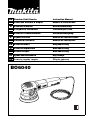
GB Random Orbit Sander
Instruction Manual
F
Ponceuse orbitale à disque
Manuel d’instructions
D
Exzenterschleifer
Betriebsanleitung
I
Levigatrice rotorbitale
Istruzioni per l’uso
NL Excenter schuurmachine
Gebruiksaanwijzing
E
Lijadora orbital
Manual de instrucciones
P
Lixadeira rotorbital
Manual de instruções
DK Excentersliber
Brugsanvisning
S
Excenterslipmaskin
Bruksanvisning
N
Eksentersliper
Bruksanvisning
SF Epäkeskohiomakone
Käyttöohje
GR Λειαvτής τυχαίας τροχιάς
Οδηγίες χρήσεως
BO6040
1
2
1
2
3
5
6
4
3
4
8
9
7
5
6
13
12
11
8
10
7
2
8
14
9
10
16
15
11
12
17
13
3
ENGLISH
Explanation of general view
1
2
3
4
5
6
Abrasive disc
Side grip
Screw
Pad
Hex wrench
Switch lever
7
8
9
10
11
12
Speed adjusting dial
Change knob
Roto-orbit mode
Random orbit mode
Dust outlet
Cuff
13
14
15
16
17
Hose
Joint
Sponge pad
Felt pad
Wool pad
SPECIFICATIONS
9.
Model
BO6040
Pad diameter ...................................................... 150 mm
Abrasive disc diameter ....................................... 150 mm
Orbits per minute ........................................ 1,600 – 5,800
Overall length ..................................................... 316 mm
Net weight ............................................................. 2.7 kg
SAVE THESE INSTRUCTIONS.
• Due to our continuing program of research and development, the specifications herein are subject to change
without notice.
• Note: Specifications may differ from country to country.
Power supply
The tool should be connected only to a power supply of
the same voltage as indicated on the nameplate, and can
only be operated on single-phase AC supply. They are
double-insulated in accordance with European Standard
and can, therefore, also be used from sockets without
earth wire.
Safety hints
For your own safety, please refer to the enclosed safety
instructions.
SPECIFIC SAFETY RULES
GEB021-1
DO NOT let comfort or familiarity with product
(gained from repeated use) replace strict adherence
to sander safety rules. If you use this tool unsafely or
incorrectly, you can suffer serious personal injury.
1. Hold power tools by insulated gripping surfaces
when performing an operation where the cutting
tool may contact hidden wiring or its own cord.
Contact with a "live" wire will make exposed metal
parts of the tool "live" and shock the operator.
2. Always use safety glasses or goggles. Ordinary
eye or sun glasses are NOT safety glasses.
3. Hold the tool firmly.
4. Do not leave the tool running. Operate the tool
only when hand-held.
5. This tool has not been waterproofed, so do not
use water on the workpiece surface.
6. Ventilate your work area adequately when you
perform sanding operations.
7. Some material contains chemicals which may be
toxic. Take caution to prevent working dust inhalation and skin contact. Follow material supplier
safety data.
8. Use of this tool to sand some products, paints
and wood could expose user to dust containing
hazardous substances. Use appropriate respiratory protection.
4
Be sure that there are no cracks or breakage on
the pad before use. Cracks or breakage may
cause a personal injury.
WARNING:
MISUSE or failure to follow the safety rules stated in
this instruction manual may cause serious personal
injury.
OPERATING INSTRUCTIONS
Installing or removing abrasive disc (Fig. 1)
Important:
• Always be sure that the tool is switched off and
unplugged before installing or removing the abrasive
disc.
• Always use hook-and-loop system abrasive discs.
Never use pressure-sensitive abrasive discs.
To install the abrasive disc, first remove all dirt or foreign
matter from the pad. Then attach the abrasive disc to the
pad, using the hook-and-loop system of the abrasive disc
and the pad. Be careful to align the holes in the abrasive
disc with those in the pad.
To remove the disc from the pad, just pull up from its edge.
Installing side grip (optional accessory) (Fig. 2)
Remove one of the screws which secure the head cover.
Screw the side grip on the tool securely. The side grip
can be installed on either side of the tool.
Changing pad (Fig. 3)
Makita offers an extensive range of optional super soft,
soft and hard pads. Remove the screw counterclockwise
from the center of the base with a hex wrench. After
changing the pad, tighten the screw clockwise securely.
Switch action (Fig. 4)
CAUTION:
Before plugging in the tool, always check to see that the
switch lever actuates properly and returns to the “OFF”
position when the side of the switch lever is depressed.
To start the tool, slide the switch lever to the “I” position.
For continuous operation, depress the front of the switch
lever and then slide to the “I” position as above.The
switch is used in this locked-on position for continuous
operation.
To stop the tool from this locked-on position, slide the
switch lever to the “O” position by depressing the rear of
the switch lever.
Speed adjusting dial (Fig. 5)
The rotating speed can be changed by turning the speed adjusting dial to a given number setting from 1 to 5. Higher
speed is obtained when the dial is turned in the direction of number 5. And lower speed is obtained when it is turned in
the direction of number 1.
Refer to the table below for the relationship between the number settings on the dial, orbits per minute and the pad
rotating speed.
Number
Orbits per min.
Roto-orbit pad rotating speed per min.
1
1,600
180
2
2,100
240
3
3,600
420
4
5,100
590
5
5,800
670
CAUTION:
• If the tool is operated continuously at low speeds for a long time, the motor will get overloaded and heated up.
• The speed adjusting dial can be turned only as far as 5 and back to 1. Do not force it past 5 or 1, or the speed adjusting function may no longer work.
Selecting action mode (Fig. 6 & 7)
Use the change knob to change the rotation mode. Roto-orbit mode is orbital action plus rotation action of pad for
rough sanding and polishing. Random orbit mode is orbital action of pad for fine sanding. Rotate the change knob
counterclockwise for roto-orbit mode and clockwise for random orbit mode.
CAUTION:
• Do not rotate the change lever when the tool is running under load. The tool will be damaged.
Typical applications for sanding and polishing
Sanding
Use / Material
Mode selection
Speed
control
setting
Pad
Paintwork:
Sanding
Repairs (scratches, rust spots)
Rough paint stripping
Random
Roto-orbit/Random
Roto-orbit
1–3
2–3
4–5
Soft
Hard
Soft
Plastics:
Soft plastics (PVC/ABS)
Hard plastics (FRP)
Roto-orbit/Random
Roto-orbit
1–3
1–3
Super soft/Soft
Soft/Hard
Woods:
Softwood
Hardwood
Veneers
Random
Roto-orbit/Random
Random
1–3
3–5
1–2
Super soft/Soft
Soft
Super Soft
Metals:
Non-ferrous metal (aluminum, copper)
Steel
Steel, rust removal
Hard metal (stainless steel)
Roto-orbit/Random
Roto-orbit
Roto-orbit
Roto-orbit
1–3
3–5
4–5
4–5
Soft
Soft/Hard
Super soft
Soft
5
Polishing
Use / Material
Speed
control
setting
Mode selection
Pad
Applying wax
Roto-orbit
2–4
Removing wax
Roto-orbit
4–5
Sponge pad
Felt pad
Polishing
Roto-orbit
4–5
Wool pad
The above information is intended only as a guide. In each case, the most appropriate sanding disc grain should be
determined by preliminary trials.
The tool equipped with electronic function is easy to operate because of the following features.
• Constant speed control
Electronic speed control for obtaining constant speed.
Possible to get fine finish, because the rotating speed is kept constant even under load condition.
• Soft start feature
Safety and soft start because of suppressed starting shock.
Dust collection (optional accessory)
(Fig. 8 & 9)
If a Makita hose is used, you can connect the cuff to the
dust outlet directly. If other hose with an inner diameter of
24 mm, attach the joint between the dust outlet and the
cuff.
Sanding operation (Fig. 10)
CAUTION:
• Never switch on the tool when it is in contact with the
workpiece, it may cause an injury to operator.
• Never run the tool without the abrasive disc. You may
seriously damage the pad.
• Never force the tool. Excessive pressure may decrease
the sanding efficiency, damage the abrasive disc or
shorten tool life.
Turn the tool on and wait until it attains full speed. Then
gently place the tool on the workpiece surface. Keep the
pad flush with the workpiece and apply slight pressure on
the tool.
Polishing operation
CAUTION:
• Use only a Makita genuine sponge pad, felt pad or wool
pad (optional accessories).
• Always operate the tool at low speed to prevent work
surfaces from heating abnormally.
• Never force the tool. Excessive pressure may decrease
the polishing efficiency and cause motor overload,
resulting in tool malfunction.
1. Applying wax (Fig. 11)
Use an optional sponge pad. Apply wax to the
sponge pad or work surface. Run the tool to smooth
out the wax.
NOTE:
First, wax a less conspicuous portion of the work
surface to make sure that the tool will not scratch the
surface or result in uneven waxing.
2. Removing wax (Fig. 12)
Use an optional felt pad. Run the tool to remove
wax.
3. Polishing (Fig. 13)
Use an optional wool pad. Run the tool and apply
the wool pad gently to the work surface.
6
MAINTENANCE
CAUTION:
Always be sure that the tool is switched off and
unplugged before carrying out any work on the tool.
To maintain product safety and reliability, repairs, maintenance or adjustment should be carried out by a Makita
Authorized Service Center.
ACCESSORIES
CAUTION:
These accessories or attachments are recommended for
use with your Makita tool specified in this manual. The
use of any other accessories or attachments might
present a risk of injury to persons. Only use accessory or
attachment for its stated purpose.
If you need any assistance for more details regarding
these accessories, ask your local Makita service center.
• Hook-and-loop system abrasive disc
(with pre-punched holes)
Grit
Use
•
•
•
•
•
•
•
•
40
60
Coarse
80
120
Medium
180
240
400
Fine
Hook-and-loop system sponge pad
Hook-and-loop system felt pad
Hook-and-loop system wool pad
Sanding cloth 150 – #100, #200, #800 for fine sanding
Pad 150 (Super Soft, Soft, Hard)
Side grip
Joint
Hex wrench
NEDERLANDS
Verklaring van algemene gegevens
1
2
3
4
5
6
Schuurschijf
Zijhandgreep
Schroef
Steunschijf
Zeskantsleutel
Schakelaar
7
8
9
10
11
12
Snelheidsregelknop
Omschakelknop
Roterend-uitslaand modus
Willekeurige modus
Stofuitlaat
Manchet
TECHNISCHE GEGEVENS
7.
Model
BO6040
Diameter steunschijf ........................................... 150 mm
Diameter schuurschijf ......................................... 150 mm
Omwentelingen per minuut ........................ 1 600 – 5 800
Totale lengte ....................................................... 316 mm
Netto gewicht ......................................................... 2,7 kg
8.
• In verband met ononderbroken research en ontwikkeling behouden wij ons het recht voor bovenstaande
technische gegevens te wijzigen zonder voorafgaande
kennisgeving.
• Opmerking: De technische gegevens kunnen van land
tot land verschillen.
Stroomvoorziening
Het gereedschap mag alleen worden aangesloten op
een stroombron van hetzelfde voltage als aangegeven op
de naamplaat, en kan alleen op enkel-fase wisselstroom
worden gebruikt. Het gereedschap is dubbel-geïsoleerd
volgens de Europese standaard en kan derhalve ook op
een niet-geaard stopkontakt worden aangesloten.
Veiligheidswenken
Voor uw veiligheid dient u de bijgevoegde Veiligheidsvoorschriften nauwkeurig op te volgen.
AANVULLENDE
VEILIGHEIDSVOORSCHRIFTEN
Laat u NIET misleiden door een vals gevoel van comfort en bekendheid met het gereedschap (na veelvuldig gebruik) en neem alle veiligheidsvoorschriften
van de schuurmachine altijd strikt in acht. Bij onveilig of verkeerd gebruik van het elektrisch gereedschap, bestaat de kans op ernstig persoonlijk letsel.
1. Houd elektrisch gereedschap vast aan het geïsoleerde oppervlak van de handgrepen wanneer u
werkt op plaatsen waar het zaaggereedschap
met verborgen bedrading of zijn eigen snoer in
aanraking kan komen. Door contact met onder
spanning staande draden, zullen de niet-geïsoleerde metalen delen van het gereedschap onder
spanning komen te staan zodat de gebruiker een
elektrische schok kan krijgen.
2. Draag altijd een veiligheidsbril. Een gewone bril
of een zonnebril is GEEN veiligheidsbril.
3. Houd het gereedschap stevig vast.
4. Schakel het gereedschap altijd uit als u weg
moet. Schakel het gereedschap alleen in wanneer u het vasthoudt.
5. Dit gereedschap is niet waterdicht. Besprenkel
derhalve het oppervlak van het werkstuk niet
met water.
6. Zorg dat uw werkplaats goed geventileerd is
wanneer u gaat schuren.
16
9.
13
14
15
16
17
Slang
Verbindingsstuk
Sponsrubberen schijf
Vilten schijf
Wollen schijf
Sommige materialen bevatten chemicaliën die
giftig kunnen zijn. Pas op dat u het werkstof van
dergelijke materialen niet inademt en vermijd
contact met de huid.Volg de veiligheidsvoorschriften van de leverancier van het materiaal
op.
Als dit gereedschap wordt gebruikt voor het
schuren van bepaalde producten, verflagen en
hout, kan de gebruiker worden blootgesteld aan
stof waarin gevaarlijke bestanddelen zitten.
Gebruik geschikte ademhalingbeschermingsapparatuur.
Controleer voor het gebruik of de schuurschijf
niet gescheurd of gebroken is. Een gescheurde
of gebroken schijf kan persoonlijk letsel veroorzaken.
BEWAAR DEZE VOORSCHRIFTEN.
WAARSCHUWING:
VERKEERD GEBRUIK of het niet naleven van de veiligheidsvoorschriften in deze gebruiksaanwijzing
kan leiden tot ernstige verwondingen.
BEDIENINGSVOORSCHRIFTEN
Installeren of verwijderen van de schuurschijf (Fig. 1)
Belangrijk:
• Kontroleer altijd of het gereedschap is uitgeschakeld en
de stekker van het netsnoer uit het stopkontakt is verwijderd alvorens de schuurschijf te installeren of te verwijderen.
• Gebruik altijd schuurschijven van het klittenband-type.
Gebruik nooit drukgevoelige schuurschijven.
Voor het installeren van de schuurschijf dient u eerst alle
vuil en stof van de steunschijf te verwijderen. Bevestig
vervolgens de schuurschijf op de steunschijf door middel
van het klittenband op de schuurschijf en steunschijf.
Zorg ervoor dat de gaten in de schuurschijf overeenkomen met de gaten in de steunschijf.
Bevestigen van de zijhandgreep
(los verkrijgbaar accessoire) (Fig. 2)
Verwijder een van de schroeven waarmee het kopdeksel
is vastgezet. Schroef de zijhandgreep stevig vast op het
gereedschap. De zijhandgreep kan aan beide zijden van
het gereedschap worden bevestigd.
Verwisselen van de steunschijf (Fig. 3)
Makita biedt een uitgebreide keuze optionele superzachte, zachte en harde steunschijven. Draai de schroef
in het midden van de gereedschapsvoet linksom los met
de zeskantsleutel en verwijder deze. Nadat de steunschijf is verwisseld, draait u de schroef goed vast naar
rechts.
Werking van de schakelaar (Fig. 4)
LET OP:
Voordat u het gereedschap op een stopcontact aansluit,
moet u altijd controleren of de schakelaar naar behoren
werkt en naar de “OFF” positie terugkeert wanneer de
zijkant van de schakelaar wordt ingedrukt.
Schuif de schakelaar naar de “I” positie om het gereedschap te starten. Voor doorlopende werking drukt u het
voorste gedeelte van de schakelaar in en dan schuift u
hem naar de “I” positie zoals hierboven. Gebruik de
schakelaar in deze vergrendelde stand om het gereedschap continu te gebruiken.
Om het gereedschap vanuit deze vergrendelde stand te
gebruiken, drukt u het achterste gedeelte van de schakelaar in en schuift u hem naar de “O” positie.
Snelheidsregelknop (Fig. 5)
U kunt de draaisnelheid veranderen door de snelheidsregelknop naar een van de cijfers 1 tot 5 te draaien. De snelheid
verhoogt wanneer u de knop in de richting van het cijfer 5 draait. De snelheid verlaagt wanneer u deze in de richting
van het cijfer 1 draait.
De onderstaande tabel toont de verhouding tussen de cijfers op de regelknop, het aantal omwentelingen per minuut
en de draaisnelheid van de steunschijf.
Cijfer
Omwentelingen per minuut
Draaisnelheid van steunschijf per minuut
in de roterend-uitslaand modus
1
1,600
180
2
2,100
240
3
3,600
420
4
5,100
590
5
5,800
670
LET OP:
• Wanneer u het gereedschap lange tijd achtereen bij een lage snelheid gebruikt, kan de motor overbelast en oververhit worden.
• De snelheidregelknop kan niet verder dan 5 en niet verder terug dan 1 worden gedraaid. Forceer de knop niet voorbij 5 en 1, aangezien de snelheidsregeling dan ontregeld kan raken.
Kiezen van de gewenste werking (Fig. 6 en 7)
Gebruik de omschakelknop om de rotatiemodus te veranderen. De roterend-uitslaand modus is uitslaande beweging
plus roterende beweging van de steunschijf voor ruw schuren en polijsten. De willekeurige modus is uitslaande beweging van de steunschijf voor fijn schuren. Draai de omschakelknop naar links voor de roterend-uitslaand modus, en
naar rechts voor de willekeurige modus.
LET OP:
• Verdraai de keuzedraaiknop niet terwijl het gereedschap nog belast draait, aangezien het gereedschap daardoor
beschadigd zal raken.
Typische toepassingen voor schuren en polijsten
Schuren
Gebruik / Materiaal
Schilderwerk:
Schuren
Herstellen (krassen, roestvlekken)
Afkrabben van ruwe verf
Rotatiemodus
Willekeurig
Roterend-uitslaand/willekeurig
Roterend-uitslaand
Kunststoffen:
Zachte kunststoffen
Roterend-uitslaand/willekeurig
(PVC Polyvinylchloride, ABS kunststoffen)
Harde kunststoffen
Roterend-uitslaand
(FRB Met vezel versterkte kunststoffen)
Instelling
snelheidsreelknop
Steunschijf
1–3
2–3
4–5
Zacht
Hard
Zacht
1–3
Superzacht/Zacht
1–3
Zacht/Hard
Hout:
Zacht hout
Hard hout
Fineerhout
Willekeurig
Roterend-uitslaand/willekeurig
Willekeurig
1–3
3–5
1–2
Superzacht/Zacht
Zacht
Superzacht
Metaal:
Nonferrometaal (aluminium, koper)
Staal
Staal, roestverwijdering
Hard metaal (roestvrij staal)
Roterend-uitslaand/willekeurig
Roterend-uitslaand
Roterend-uitslaand
Roterend-uitslaand
1–3
3–5
4–5
4–5
Zacht
Zacht/Hard
Superzacht
Zacht
17
Polijsten
Gebruik / Materiaal
Was aanbrengen
Was verwijderen
Polijsten
Rotatiemodus
Instelling
snelheidsregelknop
Steunschijf
2–4
4–5
4–5
Sponsrubberen schijf
Vilten schijf
Wollen schijf
Roterend-uitslaand
Roterend-uitslaand
Roterend-uitslaand
De bovenstaande informatie is alleen als een algemene leidraad bedoeld. De korrel van de schuurschijf die het best
geschikt is voor het te bewerken materiaal moet in elk geval afzonderlijk worden bepaald aan de hand van voorafgaande proefnemingen.
Het gereedschap dat voorzien is van de elektronische functie is gemakkelijk te bedienen omwille van de volgende kenmerken.
• Constante snelheidsregeling
Elektronische snelheidsregeling verzekert een constant toerental.
U kunt fijn afwerken, aangezien de draaisnelheid zelfs bij zware belasting constant wordt gehouden.
• Zachte start
De schok bij het starten wordt onderdrukt zodat u veiliger kunt werken en zachter kunt starten.
Stofafzuiging (los verkrijgbaar accessoire)
(Fig. 8 en 9)
Wanneer u een Makita slang gebruikt, kunt u de manchet
direct verbinden met de stofuitlaat. Bij gebruik van een
andere slang met een binnendiameter van 24 mm, moet
u het verbindingsstuk bevestigen tussen de stofuitlaat en
de manchet.
Schuren (Fig. 10)
LET OP:
• Schakel het gereedschap nooit in terwijl het in aanraking komt met het werkstukoppervlak, aangezien de
gebruiker daardoor verwonding kan oplopen.
• Schuur nooit met het gereedschap zonder dat de
schuurschijf is aangebracht. Als u dit doet, kan de
steunschijf ernstig beschadigd raken.
• Forceer nooit het gereedschap. Overmatige druk kan
leiden tot slechtere schuurprestaties, beschadiging van
de schuurschijf en een kortere levensduur van het
gereedschap.
Schakel het gereedschap in en wacht totdat het met volle
snelheid draait. Plaats daarna het gereedschap langzaam op het werkstukoppervlak. Houd de steunschijf
vlak met het werkstuk en oefen lichte druk uit op het
gereedschap.
Polijsten
LET OP:
• Gebruik uitsluitend een originele Makita sponsrubberen, vilten of wollen schijf (los verkrijgbare accessoires).
• Gebruik het gereedschap altijd met lage snelheid om
oververhitting van het werkoppervlak te voorkomen.
• Forceer nooit het gereedschap. Overmatige druk kan
leiden tot slechtere polijstprestaties, overbelasting van
de motor en eventueel defect van het gereedschap.
1. Was aanbrengen (Fig. 11)
Gebruik een los verkrijgbare sponsrubberen schijf.
Breng was aan op de sponsrubberen schijf of op het
werkoppervlak. Laat het gereedschap draaien om
de was glad te strijken.
OPMERKING:
Was eerst een onopvallend gedeelte van het werkoppervlak om er zeker van te zijn dat het gereedschap geen krassen maakt in het oppervlak en dat
de was niet ongelijkmatig wordt uitgestreken.
18
2.
3.
Was verwijderen (Fig. 12)
Gebruik een los verkrijgbare vilten schijf. Laat het
gereedschap draaien om de was te verwijderen.
Polijsten (Fig. 13)
Gebruik een los verkrijgbare wollen schijf. Laat het
gereedschap draaien en breng de wollen schijf
zachtjes aan op het werkoppervlak.
ONDERHOUD
LET OP:
Zorg er altijd voor dat het gereedschap is uitgeschakeld
en de stekker uit het stopcontact is verwijderd alvorens
onderhoud aan het gereedschap uit te voeren.
Opdat het gereedschap veilig en betrouwbaar blijft, dienen alle reparaties, onderhoud of afstellingen te worden
uitgevoerd bij een erkend Makita service centrum.
ACCESSOIRES
LET OP:
• Deze accessoires of hulpstukken worden aanbevolen
voor gebruik met het Makita gereedschap dat in deze
gebruiksaanwijzing wordt beschreven. Het gebruik van
andere accessoires of hulpstukken kan gevaar voor
persoonlijke verwonding opleveren. Gebruik de accessoires of hulpstukken uitsluitend voor het gespecificeerde doel.
Wenst u meer informatie over deze accessoires, neem
dan contact op met het dichtstbijzijnde Makita servicecentrum.
• Klittenband-type schuurschijf (voorzien van gaten)
Korrel
Gebruik
•
•
•
•
•
•
•
•
40
60
Grof
80
120
Middel
180
240
400
Fijn
Klittenbandsysteem schuimrubber polijstschijf
Klittenbandsysteem vilten polijstschijf
Klittenbandsysteem wollen polijstschijf
Schuurdoek 150 – #100, #200, #800 voor fijnschuren
Steunschijf 150 (superzacht, zacht, hard)
Zijhandgreep
Verbindingsstuk
Inbussleutel
ENH101-5
ENGLISH
ITALIANO
EC-DECLARATION OF CONFORMITY
DICHIARAZIONE DI CONFORMITÀ
CON LE NORME DELLA COMUNITÀ EUROPEA
We declare under our sole responsibility that this product
is in compliance with the following standards of standardized documents,
EN60745, EN55014, EN61000
in accordance with Council Directives, 89/336/EEC and
98/37/EC.
Dichiariamo sotto la nostra sola responsabilità che
questo prodotto è conforme agli standard di documenti
standardizzati seguenti:
EN60745, EN55014, EN61000
secondo le direttive del Consiglio 89/336/CEE e 98/37/CE.
FRANÇAISE
NEDERLANDS
DÉCLARATION DE CONFORMITÉ CE
EG-VERKLARING VAN CONFORMITEIT
Nous déclarons sous notre entière responsabilité que ce
produit est conforme aux normes des documents standardisés suivants,
EN60745, EN55014, EN61000
conformément aux Directives du Conseil, 89/336/CEE et
98/37/EG.
Wij verklaren hierbij uitsluitend op eigen verantwoordelijkheid dat dit produkt voldoet aan de volgende
normen van genormaliseerde documenten,
EN60745, EN55014, EN61000
in overeenstemming met de richtlijnen van de Raad
89/336/EEC en 98/37/EC.
DEUTSCH
ESPAÑOL
CE-KONFORMITÄTSERKLÄRUNG
DECLARACIÓN DE CONFORMIDAD DE LA CE
Hiermit erklärt wir unter unserer alleinigen Verantwortung, daß dieses Produkt gemäß den Ratsdirektiven
89/336/EWG und 98/37/EG mit den folgenden Normen
von Normendokumenten übereinstimmen:
EN60745, EN55014, EN61000.
Declaramos bajo nuestra sola responsabilidad que este
producto cumple con las siguientes normas de documentos normalizados,
EN60745, EN55014, EN61000
de acuerdo con las directivas comunitarias,
89/336/EEC y 98/37/CE.
Yasuhiko Kanzaki CE 2005
Director
Directeur
Direktor
Amministratore
Directeur
Director
MAKITA INTERNATIONAL EUROPE LTD.
Michigan Drive, Tongwell, Milton Keynes,
Bucks MK15 8JD, ENGLAND
Responsible manufacturer:
Fabricant responsable :
Verantwortlicher Hersteller:
Produttore responsabile:
Verantwoordelijke fabrikant:
Fabricante responsable:
Makita Corporation Anjo Aichi Japan
41
ENH101-5
PORTUGUÊS
NORSK
DECLARAÇÃO DE CONFORMIDADE DA CE
EUs SAMSVARS-ERKLÆRING
Declaramos sob inteira responsabilidade que este
produto obedece às seguintes normas de documentos
normalizados,
EN60745, EN55014, EN61000
de acordo com as directivas 89/336/CEE e 98/37/CE do
Conselho.
Vi erklærer på eget ansvar at dette produktet er i overensstemmelse med følgende standard i de standardiserte dokumenter:
EN60745, EN55014, EN61000,
i samsvar med Råds-direktivene, 89/336/EEC og 98/37/
EC.
DANSK
SUOMI
EU-DEKLARATION OM KONFORMITET
VAKUUTUS EC-VASTAAVUUDESTA
Vi erklærer hermed på eget ansvar, at dette produkt er i
overensstemmelse med de følgende standarder i de normsættende dokumenter,
EN60745, EN55014, EN61000
i overensstemmelse med Rådets Direktiver 89/336/EEC
og 98/37/EC.
Yksinomaisesti vastuullisina ilmoitamme, että tämä tuote
on seuraavien standardoitujen dokumenttien standardien mukainen,
EN60745, EN55014, EN61000
neuvoston direktiivien 89/336/EEC ja 98/37/EC mukaisesti.
SVENSKA
ΕΛΛΗΝΙΚΑ
EG-DEKLARATION OM ÖVERENSSTÄMMELSE
∆ΗΛΩΣΗ ΣΥΜΜΟΡΦΩΣΗΣ ΕΚ
Under eget ansvar deklarerar vi härmed att denna
produkt överensstämmer med följande standardiseringar
för standardiserade dokument,
EN60745, EN55014, EN61000
i enlighet med EG-direktiven 89/336/EEC och 98/37/EC.
∆ηλώνουµε υπ την µοναδική µας ευθύνη τι αυτ
το προιν βρίσκεται σε Συµφωνία µε τα ακλουθα
πρτυπα τυποποιηµένων εγγράφων,
EN60745, EN55014, EN61000
σύµφωνα µε τις Οδηγίες του Συµβουλίου,
89/336/EEC και 98/37/ΚE.
Yasuhiko Kanzaki CE 2005
Director
Direktør
Direktör
Direktor
Johtaja
∆ιευθυντής
MAKITA INTERNATIONAL EUROPE LTD.
Michigan Drive, Tongwell, Milton Keynes,
Bucks MK15 8JD, ENGLAND
Fabricante responsável:
Ansvarlig fabrikant:
Ansvarig tillverkare:
Ansvarlig produsent:
Vastaava valmistaja:
Υπεύθυνος κατασκευαστής:
Makita Corporation Anjo Aichi Japan
42
ENG004-2-V3
ENGLISH
ITALIANO
For European countries only
Modello per l’Europa soltanto
Noise and Vibration
The typical A-weighted sound pressure level is 78 dB (A).
Uncertainty is 3 dB (A).
The noise level under working may exceed 85 dB (A).
– Wear ear protection. –
The typical weighted root mean square acceleration
2
value is 7 m/s .
These values have been obtained according to
EN60745.
Rumore e vibrazione
Il livello di pressione sonora pesata secondo la curva A è
di 78 dB (A).
L’incertezza è di 3 dB (A).
Il livello di rumore durante il lavoro potrebbe superare gli
85 dB (A).
– Indossare i paraorecchi. –
Il valore quadratico medio di accellerazione è di 7 m/s2.
Questi valori sono stati ottenuti in conformità EN60745.
FRANÇAISE
NEDERLANDS
Pour les pays d’Europe uniquement
Alleen voor Europese landen
Bruit et vibrations
Le niveau de pression sonore pondere type A est de
78 dB (A).
L’incertitude de mesure est de 3 dB (A).
Le niveau de bruit en fonctionnement peut dépasser
85 dB (A).
– Porter des protecteurs anti-bruit. –
L’accélération pondérée est de 7 m/s2.
Ces valeurs ont été obtenues selon EN60745.
Geluidsniveau en trilling
Het typische A-gewogen geluidsdrukniveau is 78 dB (A).
Onzekerheid is 3 dB (A).
Tijdens het werken kan het geluidsniveau 85 dB (A) overschrijden.
– Draag oorbeschermers. –
De typische gewogen effectieve versnellingswaarde is
2
7 m/s .
Deze waarden werden verkregen in overeenstemming
met EN60745.
DEUTSCH
ESPAÑOL
Nur für europäische Länder
Para países europeos solamente
Geräusch- und Vibrationsentwicklung
Der typische A-bewertete Schalldruckpegel beträgt
78 dB (A).
Die Abweichung beträgt 3 dB (A).
Der Lärmpegel kann während des Betriebs 85 dB (A)
überschreiten.
– Gehörschutz tragen. –
Der gewichtete Effektivwert der Beschleunigung beträgt
2
7 m/s .
Diese Werte wurden gemäß EN60745 erhalten.
Ruido y vibración
El nivel de presión sonora ponderada A es de 78 dB (A).
Incerteza 3 dB (A).
El nivel de ruido en condiciones de trabajo puede que
sobrepase los 85 dB (A).
– Póngase protectores en los oídos. –
El valor ponderado de la aceleración es de 7 m/s2.
Estos valores han sido obtenidos de acuerdo con
EN60745.
43
ENG004-2-V3
PORTUGUÊS
NORSK
Só para países Europeus
Gjelder bare land i Europa
Ruído e vibração
O nível normal de pressão sonora A é 78 dB (A).
A incerteza é de 3 dB (A).
O nível de ruído durante o trabalho pode exceder
85 dB (A).
– Utilize protectores para os ouvidos –
O valor médio da aceleração é 7 m/s2.
Estes valores foram obtidos de acordo com EN60745.
Støy og vibrasjon
Det vanlige A-verktet lydtrykksnivå er 78 dB (A).
Usikkerheten er på 3 dB (A).
Under bruk kan støynivået overskride 85 dB (A).
– Benytt hørselvern. –
Den vanlig belastede effektiv-verdi for akselerasjon er
2
7 m/s .
Disse verdiene er beregnet eller målt i samsvar med
EN60745.
DANSK
SUOMI
Kun for lande i Europa
Vain Euroopan maat
Lyd og vibration
Det typiske A-vægtede lydtryksniveau er 78 dB (A).
Der er en usikkerhed på 3 dB (A).
Støjniveauet under arbejde kan overstige 85 dB (A).
– Bær høreværn. –
Den vægtede effektive accelerationsværdi er 7 m/s2.
Disse værdier er beregnet i overensstemmelse med
EN60745.
Melutaso ja tärinä
Tyypillinen A-painotettu äänenpainetaso on 78 dB (A).
Epävarmuus on 3 dB (A).
Melutaso työpaikalla saattaa ylittää 85 dB (A).
– Käytä kuulosuojaimia. –
Tyypillinen kiihtyvyyden painotettu tehollisarvo on
2
7 m/s .
Nämä arvot on mitattu normin EN60745 mukaisesti.
SVENSKA
ΕΛΛΗΝΙΚΑ
Endast för Europa
Μ/νο για χώρες της Ευρώπης
Buller och vibration
Den typiska-A-vägda ljudtrycksnivån är 78 dB (A).
Osäkerheten är 3 dB (A).
Bullernivån under pågående arbete kan överstiga
85 dB (A).
– Använd hörselskydd –
Det typiskt vägda effektivvärdet för acceleration är
2
7 m/s .
Dessa värden har erhållits i enlighet med EN60745.
Θ/ρυβος και κραδασµ/ς
Η τυπική Α-µετρούµενη ηχητική πίεση είναι
78 dB (A).
Η Αβεβαιτητα είναι 3 dB (A).
Η ένταση ήχου υπο συνθήκες εργασίας µπορεί να
µπερβεί τα 85 dB (A).
– Φοράτε ωτοασπίδες. –
Η τυπική αξία της µετρούµενης ρίζας του µέσου
τετραγώνου της επιτάχυνσης είναι 7 m/s2.
Αυτές οι τιµές έχουν σηµειωθεί σύµφωνα µε το
ΕΝ60745.
Makita Corporation
Anjo, Aichi, Japan
884338B996