1
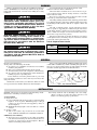
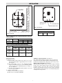
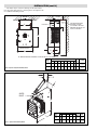
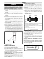
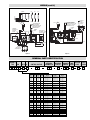
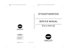
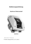
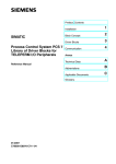
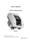
Chromalox
®
SERVICE REFERENCE
Installation, Operation
4
DIVISION
and
SALES
REFERENCE
MAINTENANCE
SECTION
HVH
PF203-4
(Supersedes PF203-3)
161-305679-001
DATE
OCTOBER, 2008
Type HVH Horizontal/Vertical Unit Heater
Specifications — Table A
Electrical Data (60 Hz)
Dimensions (In.)
BTU
A
Height
B
Width
C
Depth
Standard
Contactor
Rating (Qty.)
Wiring
Diagram
Figure
8,850
16-1/8
13
10
——
10
——
30A (1)
——
30A (1)
——
30A (1)
——
30A (1)
——
30A (1)
——
30A (1)
50A (1)
30A (1)
30A (1)
30A (1)
30A (1)
30A (1)
50A (1)
30A (1)
30A (1)
30A (1)
30A (1)
50A (1)
50A (1)
30A (1)
50A (1)
50A (1)
30A (1)
10
12
10
12
10
11
10
12
10
12
10
13
Model
HVH-02-81
HVH-02-21
HVH-02-71
HVH-04-81†
HVH-04-83†
HVH-04-21†
HVH-04-23†
HVH-04-71
HVH-04-43
HVH-05-81†
HVH-05-83†
HVH-05-21†
HVH-05-23†
HVH-05-71
HVH-05-43
HVH-07-81†
HVH-07-83
HVH-07-21†
HVH-07-23
HVH-07-71
HVH-07-43
HVH-10-81†
HVH-10-83
HVH-10-21†
HVH-10-23
HVH-10-43
HVH-12-83
HVH-12-23
HVH-12-43
HVH-15-83
HVH-15-23
HVH-15-43
Volts
Watts
Phase
Amps
208
208/240
277
2,667
2000/2,667
2,667
208
4,000
208/240
3,000/4,000
277
480
4,000
4,000
208
5,000
208/240
3,750/5,000
277
480
5,000
5,000
208
7,500
208/240
5,625/7,500
277
480
7,500
7,500
208
10,000
208/240
7,500/10,000
480
208
208/240
480
208
208/240
480
10,000
12,500
9,375/12,500
12,500
15,000
11,250/13,000
15,000
1
1
1
1
3
1
3
1
3
1
3
1
3
1
3
1
3
1
3
1
3
1
3
1
3
3
3
3
3
3
3
3
12.8
11.1*
9.6
19.2
11.2
16.7*
9.6*
14.5
4.8
24.0
13.8
20.8*
12.1*
18.2
6.0
36.1
20.9
31.1*
18.1*
27.2
9.0
48.0
27.8
41.7*
24.0*
12.0
34.8
30.1*
15.1
41.8
36.2*
18.1
13,661
16-1/8
13
10
17,076
16-1/8
13
10
25,598
20-5/8
17-1/8
12-3/4
34,130
42,663
51,195
20-5/8
20-5/8
20-5/8
17-1/8
17-1/8
17-1/8
* Note: 208V amperage is 86% of 240V value.
† These models can be field changed from single phase to three phase or three phase to single phase.
© 2010 Chromalox®, Inc.
12-3/4
12-3/4
12-3/4
12
13
12
13
12
13
12
13
WARNING
Do not mount mercury type thermostat directly on unit.
Vibration could cause heater to malfunction.
The heater must be mounted at least 7' above the floor to prevent accidental contact with the heating elements or fan blade
which could cause injury.
Keep at least 5' clearance in front of the heater. Refer to Table
D for side, top and back clearance requirements.
The ceiling mounting structure and the anchoring provisions must
be of sufficient strength to support the combined weight of the heater
and mounting bracket. (Refer to Table B for weights of heater and
bracket.)
The wall or mounting surface, and the anchoring provisions
must be capable of supporting the combined weight of the heater
and mounting brackets cantilevered from the mounting surface.
(Refer to Table B for weights of heater and brackets and for cantilevered force expressed in foot-pounds.)
Fan blade rotation must be checked. If airflow is not moving
out through the louvers, interchange any two of the three customer
power leads on three-phase units only.
Failure to understand and follow these installation instructions
and the “WARNING” notes therein may result in serious personal
injury from electrical shock, or from the heater falling due to faulty
installation.
This heater is not intended for use in hazardous
atmospheres where flammable vapors, gases, liquids or other combustible atmospheres are present
as defined in the National Electric Code. Failure to
comply can result in explosion or fire. For these
applications see PDS CXH-A-EP (PF490).
ELECTRIC SHOCK HAZARD. Disconnect all power
before installing or servicing heater. Failure to do
so could result in personal injury or property damage. Heater must be installed or serviced by a qualified person in accordance with the National
Electrical Code, NFPA 70.
Table B – Weights of Heater & Bracket
ELECTRIC SHOCK HAZARD. Any installation involving electric heaters must be performed by a qualified person and must be effectivley grounded in
accordance with the National Electrical Code to
eliminate shock hazard.
Model
Ceiling
Weight
HVH-02 to HVH-O5
HVH-07 to HVH-15
27
55
WEIGHT (Lbs.) Heater and Brackets
Wall
Weight
Ft.-Lbs.
25-1/2
67-1/4
48
112
GENERAL
Large rooms require multi-unit installation. Number and capacity
of units will be determined by volume of building and square feet of
floor area to be heated. Arrange units to provide perimeter air circulation where each unit supports the air stream from another.
Heater Location Instructions:
Arrange units so their discharge air streams:
A. Are subjected to a minimum of interference from columns,
machinery and partitions.
B. Wipe exposed walls without blowing directly at them.
C. Are directed away from room occupants in comfort heating.
D. Are directed along the windward side when installed in a
building exposed to a prevailing wind.
Locate thermostat on interior partition walls or posts away
from cold drafts, internal heat sources and away from heater discharge air streams.
Small rooms can be heated by one unit heater. Where two walls
are exposed, the heater should be mounted as shown in Figure 1.
Exposed
d
Expose
Ex
po
se
d
po
Ex
d
po
se
Ex
d
se
Exposed
Figure 1 - Single and Multi Unit Mounting
INSTALLATION
NOTICE – These heaters are designed for wall and ceiling mount.
Other modes of mounting void factory warranty.
B. Securely attach the four (4) mounting rods to the ceiling.
(Refer to Table D for wall and ceiling clearances, and
Figure 2 for mounting spacing specifications.)
Vertical Air Flow
1. Height above floor
A. It is recommended that the heater only be used with ceiling
heights of 12 feet or greater. Minimum spacing to ceiling is
6 inches, use 3/8-18” thread stock (supplied by others) as
shown in Figure 3.
B. Mimimum mounting height is 10 feet from floor to bottom
of heater.
2. Spacing to walls.
A. Side of case to wall 6”. Top or bottom of case to back wall is
10-1/4” (HVH-02 to HVH-05) and 13” (HVH-07 to HVH-15).
CEILING (Vertical Airflow):
A. The heater can be rod mounted to the ceiling by installing
four (4) threaded mounting rods in the threaded holes located on the top of the heater as shown in Figure 3. (Refer to
Table C for mounting rod thread size.)
Figure 2 - Wall and Ceiling Clearance
2
INSTALLATION
3/8-18 THREADED
MOUNTING HOLES
X
X
Side Wall
L2
CL
CL
TERMINAL BOX
ACCESS DOOR
L1
KO FOR POWER WIRING
KO FOR CONTROL WIRING
TERMINAL BOX
ACCESS DOOR
Figure 4 - Heater Back View
Back Wall
Knockout Sizes
HVH-02 - 05
HVH-07 - 15
Figure 3 - Rod Spacing
1/2”
1/2”
3/4” (1)
1” (1)
Table C — Rod Thread Type and Spacing Dimensions (inches) for
Vertical Discharge.
Unit
2-5 kW
7-1/2 - 15 kW
Rod
Thread Type
3/8 - 16
3/8 - 16
L1
2-7/8
4-5/16
Dimensions – (In.)
L2
7-1/8
9-3/8
X
3-3/4
5-1/2
Table D — Clearance Requirements (Vertical Discharge)
Model
HVH-02
Thru
HVH-05
HVH-07
Thru
HVH-15
Back
to Wall
Mounting Limitations (In.)
Side
to Wall
Top to
Ceiling
10-1/4
6
6
13
6
6
CEILING – Horizontal Airflow (See Figure 5):
The ceiling mounting bracket is fastened to the top of the heater
using the four (4) bolts supplied with the mounting bracket. The
bracket is then mounted to the ceiling using a 5/8" bolt (by others).
Horizontal Air Flow
1. Height above floor
A. In areas where ceiling height is more that 12 feet, recommended mounting height is approximately 10 feet to underside of heater.
B. For ceiling heights of 12 feet or less, maximum mounting
height is detemined by the use of the mounting bracket
offered for these heaters. Minimum spacing to ceiling is 73/4”. (See Figure 5)
C. In either case, the mimimum mounting height is 7 feet from
floor to bottom of heater.
2. Spacing to adjacent walls.
A. Rear of case to back wall 2 minimum.
B. Side of case to side wall 6” minimum.
WALL – Horizontal Airflow (See Figure 6):
Wall mounting necessitates the use of both an adaptor mounting
bracket and a wall mounting bracket. First, attach the ceiling
mounting bracket to the heater. Then, attach the wall mounting
bracket to the wall using four 5/16" bolts (by others). Attach the
ceiling mounting bracket on the heater to the wall mounting bracket using the 5/8" bolt provided.
3
INSTALLATION (cont’d.)
The heater may be rotated to discharge in the desired direction. Open and adjust louvers to desired position. See Figure 5 and
6 for additional mounting details.
CEILING
CEILING
M
FOR SWIVEL MOUNTING
TO CEILING, USE ONE
5/8" LAG BOLT. FOR FIXED
MOUNTING TO CEILING, USE
FOUR 3/8" LAG BOLTS
U
CL OF BOLT
V
WALL
A
BACK OF HEATER
N
B
C
W
W= MINIMUM DISTANCE FROM WALL TO ALLOW FOR FULL 180˚ SWIVEL
Bracket
Model
No.
Figure 5 - Optional Ceiling Swivel Mounting Bracket
Dimensions (In.)
A
B
C
M
N
HVC-1
16-1/8
13
10
8-3/8
5-3/4
HVC-2
20-5/8 17-1/8 12-3/4 10-3/4 6-3/4
W
Wt.
(Lbs.)
Use With
7-3/4 9-3/4
12
4
HVH-02,
04, 05
7-3/4
12
8
HVH-07, 10
12, 15
U
V
13
R
S
P
ADAPTOR
BRACKET
Q
T
Figure 6 - Optional Swivel Mounting Bracket
4
Bracket
Model
No.
Dimensions (In.)
P
Q
R
S
T
Bracket
Weight
(Lbs.)
Use
With
HVW1
6-1/16 18-7/8
7
5
17-5/8
3-3/4
HVH-02,
04, 05
HVW2
6-1/16
7
5
18-5/8
6-1/2
HVH-07,
10, 12, 15
23-1/4
WIRING
ELECTRIC SHOCK HAZARD. Be sure electricity is
turned off at main switch first before wiring. Any
installation involving electric heaters must be
effectively grounded in accordance with the
National Electrical Code to eliminate shock hazard.
1. Use heater only on the voltage and frequency specified on the
nameplate.
2. All wiring should be done in accordance with local codes and
the National Electrical Code by a qualified person as defined in
the NEC.
3. Two knockouts are provided on the back of the heater for wire
entry. See Figure 4 for location of knockouts.
4. Branch circuit wire for connection to heater must be at least
60˚C wire.
5. The bottom access door is hinged. There are two screws that
must be removed to gain access (Figure 3).
6. A ground wire is provided near the power connection point.
The ground wire should be connected before other connections are made.
7. Terminals on contactor or on line voltage terminal block are
supplied to be connected to accept the correct size power supply wire. Copper rated at 600V and 60˚C is satisfactory for the
heater branch circuit.
8. Electrical accessories, either kits or factory-installed options, are
shown connected by a dash line on the heater wiring diagram.
9. Wiring connections are to be made on designated wire leads as
shown in the wiring diagrams located inside the access door.
10. Louver adjustment (Do not attempt to adjust while heater is
operational): Louvers have been preset at factory with the
minimum open angle. Decreasing the 45˚ angle may result in
high temperatures and functioning of the over temperature control. To increase the opening angle, grasp the left end of louver
with the left hand using the index finger and thumb. Grasp right
end of louver with right hand in the same manner. Twist louver
Top of Heater
45˚ Min.
All Louvers
Figure 7 - Louver Adjustment
to the desired position.
POWER DISCONNECT SWITCH
(Available as a kit or factory installed option). This switch disconnects the power to the power leads when the handle is turned to
its off position. Refer to Instruction Sheet PF207.
1. Use copper conductor supply wire only when connecting to the
power line. (See Figure 8.)
2. Connection to the switch pigtails should be made with compression connectors and the joint should be then well insulated.
3. Consult the local wiring code in your area.
SUMMER FAN SWITCH - Refer to Instruction sheet PF205
without relay, PF206 with relay.
(MOUNTED ON FRONT OF HEATER). When the switch
handle is pointing toward the SUMMER (FAN ON) position, the
fan will run continuously. When the switch handle is pointing
toward the WINTER (HEAT) position, the fan will run only when
the heating elements are hot.
5
REMOTE SUMMER FAN SWITCH
(MANUAL SWITCH-LINE VOLTAGE). The wall switch is
packed in the wiring compartment. The remote fan switch is
mounted external and remote from the HVH unit heater. The voltage of the remote fan switch is the same as the supply voltage to
the HVH heater.
1. Use 14 gauge copper, NEC Class 1, 600V rated insulated wire.
Wiring must meet all Local and NEC requirements for 480-volt
service.
2. Install the remote fan switch in standard wall box in any convenient location that is protected from traffic or other accidental
damage.
3. Connect the 14 gauge copper field wire to the switch lead wires
with suitable connectors.
Contactor
or Terminal
Block
Power
Disconnect
Switch
To
Power
Supply
L1
S1
L2
S2
L3
S3
See Notes
See
Note 2
Notes:
1. This illustration shows wiring hook up for three phase service. Remove lead
wires marked L3 and S3 when using single phase power service.
2. For units without contactors, disconnect switch is to be wired to terminal block
on heater power.
3. Use copper supply wire only with this switch.
Figure 8 - Power Disconnect Switch Wiring Diagram
REMOTE FAN SWITCH
480V + Heaters, require an additional fan relay. (Available as
a kit or factory installed option). The wall switch is packed in the
wiring compartment.
1. Use 18 gauge (min.) NEC Class 1, 600V wiring that meets all
Local and NEC requirements.
2. Install the wall switch in a standard wall box in any convenient
location that is protected from traffic or other accidental damage.
3. Connect the field wire to the switch lead wires with suitable
connectors.
OPTIONAL THERMOSTAT (HVH-TK) Refer to Instruction
Sheet PF204.
Heaters can be equipped with an optional thermostat of the
Bulb and Capillary type for automatic temperature control (Figure
8). The thermostat controls the heating elements and fan simultaneously to achieve set temperature.
The “Lo” setting of the thermostat is approximately 40˚F, and
the “Hi” setting is approximately 90˚F.
Chromalox
Figure 9 — Thermostat Location, Front View
WIRING (cont’d.)
CONTROL VOLTAGE WIRING — EXTERNAL REMOTE
THERMOSTATS AND FAN SWITCHES
voltage motor switch (remote fan switch without relay).
2. The thermostat should be located in the area to be heated on an
inside wall. The thermostat should not be exposed to drafts,
sunlight, radiation from hot objects, or in a direct line with the
discharge from the unit heater.
3. Install the thermostat approximately 5 feet above the floor line.
4. Install the remote fan switch in any convenient location that is
protected from traffic or likely accidental damage.
5. Internal optional controls are shown on the unit heater wiring
diagrams by a dash line.
Line voltage is present on some of the terminals.
Always disconnect the power from the heater
before making any connections.
1. Use 600 volt, NEC Class 1 insulated wiring with a minimum
gage of 18 for thermostats and minimum gauge of 14 for line
See Note #2
Optional Thermostat
Built-in or Field Installed
Motor
Optional thermostat
built-in or field
installed
Blue
Blue
3Ø Wiring
Optional disconnect switch
built-in or field installed
Power
60 Hz
1Ø Element wiring
(Omit for 2 element
heaters)
TO T1
TO T2
TO T3
Motor
Elements
Yellow
Sec
Blue
T1
T2
T3
C1
L1
L2
C3
C2
L3
Pink
T1
T2
Optional
Disconnect
switch
built-in
or field
installed
Terminal
Block
L1
L2
Black
Red
Cutout
T3
L3
Cutout
Remove jumper wire when
thermostat is used
Power 60 Hz
NOTES:
1. Omit "L3" wiring for 1ø heaters
2. 3ø Motors used on all 480V, 7.5KV or higher
Figure 11
Figure 10
See Note #2
Optional thermostat
built-in or field installed
Motor
Optional
thermostat
built-in or
field installed
Motor
3Ø Wiring
3Ø Wiring
TO T1
TO T1
TO T2
TO T3
TO T3
TO T2
TO T1
TO T1
TO T2
TO T3
TO T3
TO T2
SEC
Yellow
Blue
T1
Purple
Orange
T3
T2
1Ø Wiring
C1
C2
C3
TO T1 TO T1 TO T1
T1
T2
T3
L1
C1
L1
L2
C2
L3
Cutout
Remove jumper wire
when thermostat
is used
Power 60 Hz
TO T2 TO T2 TO T2
L3
Pink
Remove jumper wire
when thermostat is used
Optional
disconnect
switch
built-in
or field
installed
Pink
Optional
disconnect
switch
built-in
or field
installed
L2
C3
Black
Black/Red
Cutout
1Ø Wiring
TO T1 TO T1 TO T1
Power 60 Hz
Notes: 1 Omit "L3" wiring for 1ø heaters
Notes:
1. Omit "L3" wiring for 1ø heaters
2. 3Ø motors used on all 480V 7.5Kw or higher heaters.
All other heaters use 1ø motors.
Figure 12
Figure 13
6
TO T2 TO T2 TO T2
WIRING (cont’d.)
1Ø WIRING
3Ø WIRING
TO T1
TO T1
TO T1
TO T2
TO T2
TO T2
TO T1
TO T1
TO T2
TO T3
TO T3
TO T2
1 OR 3Ø
M
1 OR 3Ø
OPTIONAL THERMOSTAT
BUILT-IN OR REMOTE
(WHEN THERMOSTAT IS NOT
USED THERE'S A JUMPER
BETWEEN C1 AND C2)
SUMMER FAN
SWITCH BUILT-IN
OR REMOTE
MOUNTED
TERMINAL
BLOCK
CONTACTOR
T2
T1
8
9
1
2
3
L1
L2
7
CONTACTOR
TRANSFORMER ON
480V HEATERS, OPTIONAL
ON LOWER VOLTAGES
6T3
1L1
5L3
T1
A1
4T2
2T1
1
T2 T3
X1
X2
H1
H2
C1 C2 C3
3L2
C1 C2 C3
7
FAN SWITCH,
BUILT-IN
OR REMOTE
MOUNTED
10
TERMINAL
BLOCK
T3
10 11 12
OPTIONAL THERMOSTAT
BUILT-IN OR REMOTE
(WHEN THERMOSTAT IS NOT
USED THERE'S A JUMPER
BETWEEN C1 AND C2)
M
L1
A2
L2 L3
MOTOR
RELAY
11
12
9
8
2
3
TRANSFORMER
CUTOUT
L3
3Ø MOTOR WIRING
CUTOUT
OPTIONAL
DISCONNECT
SWITCH BUILT-IN
OR FIELD INSTALLED
POWER 60 HZ
Figure 15
Figure 14
RENEWAL PARTS IDENTIFICATION
PRODUCT
TYPE
kW
VOLTS Ø
CONTROL VOLTAGE
INTEGRAL
THERMOSTAT
INTEGRAL
DISCONN.
SWITCH
POWER
FAN ONLY TIME ON PILOT OUTLET
SWITCH DELAY LIGHT SCREEN
H V H
Code
No.
kW
Volts
Phase
Element
Part No.
Motor
Part No.
Fan
Part No.
02-81
02-21
02-71
04-81
04-83
04-21
04-23
04-71
04-43
05-81
05-83
05-21
05-23
05-71
05-43
07-81
07-83
07-21
07-23
07-71
07-43
10-81
10-83
10-21
10-23
10-43
12-83
12-23
12-43
15-83
15-23
15-43
2.67
2.67
2.67
4
4
3/4
3/4
4
4
5
5
3.75/5
3.75/5
5
5
7.5
7.5
5.6/7.5
5.6/7.5
7.5
7.5
10
10
7.5/10
7.5/10
10
12.5
9.4/12.5
12.5
15
11.2/15
15
208
208/240
277
208
208
208/240
208/240
277
480
208
208
208/240
208/240
277
480
208
208
208/240
208/240
277
480
208
208
208/240
208/240
480
208
208/240
480
208
208/240
480
1
1
1
1
3
1
3
1
3
1
3
1
3
1
3
1
3
1
3
1
3
1
3
1
3
3
3
3
3
3
3
3
118-305631-001
118-305631-002
118-305631-003
118-305631-001
118-305631-001
118-305631-002
118-305631-002
118-305631-003
118-305631-003
118-305631-004
118-305631-004
118-305631-005
118-305631-005
118-305631-006
118-305631-007
318-305659-007
318-305659-007
318-305659-008
318-305659-008
318-305659-009
318-305659-010
318-305659-001
318-305659-001
318-305659-002
318-305659-002
318-305659-003
318-305659-004
318-305659-005
318-305659-006
318-305659-007
318-305659-008
318-305659-010
193-302912-001
193-302912-001
193-302120-001
193-302912-001
193-302912-001
193-302912-001
193-302912-001
193-302120-001
193-302912-003
193-302912-001
193-302912-001
193-302912-001
193-302912-001
193-302120-001
193-302912-003
193-302912-004
193-302912-004
193-302912-004
193-302912-004
193-302120-004
193-302912-005
193-302912-004
193-302912-004
193-302912-004
193-302912-004
193-302912-005
193-302912-004
193-302912-004
193-302912-005
193-302912-004
193-302912-004
193-302912-005
112-302997-001
112-302997-001
112-130367-001
112-302997-001
112-302997-001
112-302997-001
112-302997-001
112-130367-001
112-302997-001
112-302997-001
112-302997-001
112-302997-001
112-302997-001
112-130367-001
112-302997-001
112-130367-002
112-130367-002
112-130367-002
112-130367-002
112-130367-002
112-130367-002
112-130367-002
112-130367-002
112-130367-002
112-130367-002
112-130367-002
112-130367-002
112-130367-002
112-130367-002
112-130367-002
112-130367-002
112-130367-002
7
2, 4, 7, 8
2, 4, 7, 8
2, 4, 7, 8
2, 4, 8
7
2, 4, 7, 8
2, 4, 7, 8
2, 4, 7, 8
2, 4, 7, 8
2, 4, 8
7
2, 4, 7, 8
2, 4, 7, 8
2, 8
2, 8
7
7
kW
-00
VOLTS
-0
Ø
0
00
30
30
30
30
31
31
32
32
32
32
33
33
34
34
35
35
=
=
=
=
=
=
=
=
=
=
=
=
=
=
=
=
=
VOLTS Ø
CONTROL VOLTAGE
-00
kW
2150 N. RULON WHITE BLVD., OGDEN, UT 84404
Phone: 1-800-368-2493
www.chromalox.com
TA - Q7 - EF
Litho in U.S.A.
0 = No Time Delay Relay
R = 24V Relay P/N 072-071847-040
R = 120V Relay P/N 072-071847-041
TIME DELAY
-0
Miscellaneous Parts
Thermostat Knob
169-049278-001
No Disconnect Switch
3PST Switch P/N 292-057673-001
3PST Switch P/N 292-057673-001
24V Motor Relay P/N 072-123534-075
120V Motor Relay P/N 072-123534-064
PF204
PF205
PF206
PF207
OUTLET SCREEN
-0
0 = No Outlet Screen
0 = No Pilot Light
P = 24V P/N 213-072380-029 S = 2-5 kW P/N 247-305642-001
P = 120V P/N 213-072380-007 S = 7-15 kW P/N 247-305642-002
FAN ONLY SWITCH
-00
Limited Warranty:
Please refer to the Chromalox limited warranty applicable to this product at
http://www.chromalox.com/customer-service/policies/termsofsale.aspx.
Cutout Switch
2.6 through 5 kW
300-024413-001
7.5 through 15 kW
300-024413-002
D0 =
FI =
FE =
FI =
FI =
0 = No Disconnect Switch
D = 50A P/N 292-303472-007
Instruction Sheets
No Thermostat
SPST P/N 300-049197-003
DPST P/N 300-049197-004
SPST P/N 300-049197-001
DPST P/N 300-049197-002
PILOT LIGHT
-0
POWER
FAN ONLY TIME ON PILOT OUTLET
SWITCH DELAY LIGHT SCREEN
DISCONNECT
SWITCH
-0
INTEGRAL
DISCONN.
SWITCH
1. INTERNAL THERMOSTAT
2. INTERNAL/EXTERNAL SUMMER FAN SWITCH
3. INTERNAL/EXTERNAL SUMMER FAN SWITCH W/RELAY
4. DISCONNECT SWITCH
00 =
TL =
TL =
TH =
TH =
INTEGRAL
THERMOSTAT
INTEGRAL
THERMOSTAT
-00
CONTROL VOLTAGE
No Contactor
24V 35A Contactor P/N 072-304551-001
24V 50A Contactor P/N 072-303180-002
Transformer P/N 315-304252-002
Transformer P/N 315-304252-004
24V 35A Contactor P/N 072-304551-001
24V 50A Contactor P/N 072-303180-002
120V 35A Contactor P/N 072-304551-007
120V 50A Contactor P/N 072-304551-008
Transformer P/N 315-304252-001
Transformer P/N 315-304252-003
120V 35A Contactor P/N 072-304551-007
120V 50A Contactor P/N 072-304551-008
208/240V 35A Contactor P/N 072-304551-013
208/240V 50A Contactor P/N 072-304551-014
277V 35A Contactor P/N 072-304551-019
277V 50A Contactor P/N 072-304551-020
H V H
PRODUCT
TYPE
RENEWAL PARTS IDENTIFICATION (cont’d.)