1
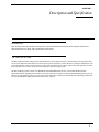
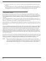
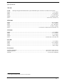
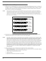
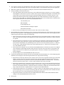
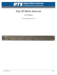
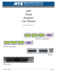
TM-2000 Trunk Master
MTM-2000 Mini-Trunk Master
SWP-2000 Switch Over Panel
ICP-2000 Interconnect Panel
User Manual
TM-2000
ICP-2000
9350-7715-000 Rev H
MTM-2000
SWP-2000
4/2008
PROPRIETARY NOTICE
SHIPPING TO THE MANUFACTURER
The product information and design disclosed herein were originated by
and are the property of Telex Communications, Inc. Telex reserves all
patent, proprietary design, manufacturing, reproduction, use and sales
rights thereto, and to any article disclosed therein, except to the extent
rights are expressly granted to others.
All shipments of product should be made via UPS Ground, prepaid (you
may request from Factory Service a different shipment method). Any
shipment upgrades will be paid by the customer. The equipment should
be shipped in the original packing carton. If the original carton is not
available, use any suitable container that is rigid and of adequate size. If
a substitute container is used, the equipment should be wrapped in paper
and surrounded with at least four (4) inches of excelsior or similar
shock-absorbing material. All shipments must be sent to the following
address and must include the Proof of Purchase for warranty repair.
Upon completion of any repair the equipment will be returned via
United Parcel Service or specified shipper, collect.
COPYRIGHT NOTICE
Copyright 2008 by Telex Communications, Inc. All rights reserved.
Reproduction, in whole or in part, without prior written permission from
Telex is prohibited.
WARRANTY NOTICE
See the enclosed warranty card for further details.
CUSTOMER SUPPORT
Technical questions should be directed to:
Customer Service Department
RTS/Telex Communications, Inc.
12000 Portland Avenue South
Burnsville, MN 55337 USA
Telephone: 800-392-3497
Fax: 800-323-0498
RETURN SHIPPING INSTRUCTIONS
Customer Service Department
Telex Communications, Inc. (Lincoln, NE)
Telephone: 402-467-5321
Fax: 402-467-3279
Factory Service: 800-553-5992
Please include a note in the box which supplies the company name,
address, phone number, a person to contact regarding the repair, the type
and quantity of equipment, a description of the problem and the serial
number(s).
Factory Service Department
Telex Communications, Inc.
8601 East Cornhusker Hwy.
Lincoln, NE 68507 U.S.A.
Attn: Service
This package should include the following:
Quantity
1
Description
Part Number
TM-2000 Final Assembly
90107715000
1
TM-2000 User Manual
93507715000
1
Cable, RS232, ADAM CS
90207297052
1
Trunk Edit Software Assy
90157715100
1
Warranty Statement
38110387
Table
of
Contents
DESCRIPTION AND SPECIFICATION ................................................................................................... 3
Introduction ...............................................................................................................................................................3
TM-2000/MTM-2000 .................................................................................................................................................3
FRONT PANEL FEATURES ..........................................................................................................................................................4
REAR PANEL FEATURES ............................................................................................................................................................5
ICP-2000 Description ...............................................................................................................................................6
FRONT PANEL FEATURES ..........................................................................................................................................................6
REAR PANEL FEATURES ............................................................................................................................................................6
SWP-2000 Description ..............................................................................................................................................6
FRONT PANEL FEATURES ..........................................................................................................................................................7
REAR PANEL FEATURES ............................................................................................................................................................7
Understanding Trunking ...........................................................................................................................................8
Specifications .............................................................................................................................................................9
TM-2000 ..................................................................................................................................................................................9
MTM-2000 ..............................................................................................................................................................................9
SWP-2000 ...............................................................................................................................................................................9
ICP-2000 .................................................................................................................................................................................9
ENVIRONMENT ..........................................................................................................................................................................9
INSTALLATION ........................................................................................................................................ 11
Installing Software ..................................................................................................................................................11
Rack Mounting .........................................................................................................................................................11
Trunking Connections and Setup ............................................................................................................................12
Licensing for the TM-2000/MTM-2000 ...................................................................................................................15
Software Organization ............................................................................................................................................15
Hardware Requirements ..........................................................................................................................................15
SERIAL PORTS .........................................................................................................................................................................15
ETHERNET ADAPTERS .............................................................................................................................................................15
TM-2000/MTM-2000 Software Installation Configuration Options .......................................................................16
Updating the TM-2000/MTM-2000 Software ..........................................................................................................17
RECOMMENDED CABLES .........................................................................................................................................................23
USEFUL LINUX TRICKS ......................................................................................................................... 25
CHAPTER 1
Description and Specification
Introduction
This manual describes the installation and operation of the TM-2000/MTM-2000 Trunk Master and Mini-Trunk Master,
SWP-2000 Switch Over Panel, and ICP-2000 Interconnect Panel.
TM-2000/MTM-2000
The RTS Trunking System manages intercommunications between separate intercom systems using intercom ports that have
been reserved and interconnected between the intercom systems. Keypanels or other data devices can then communicate with
various destinations in other intercom systems via the reserved intercom ports. (This is different from bus expansion, in which
the bus system of two or more frames are interconnected to form one larger system.)
The RTS Trunking System consists of an RTS Model TM-2000/MTM-2000 and one or more RTS Model ICP-2000
Interconnect Panels, depending on the number or intercom systems to be trunked. A backup TM-2000/MTM-2000 may also be
added to prevent downtime in the event of a failure of the main master control unit. When both main and backup control units
are used, an RTS Model SWP-2000 Switch Over Panel is required.
3
Front Panel Features
FIGURE 1.
1.
2.
3.
4.
TM-2000 front panel features. (Drawing not to scale)
Status indicators for power, hard drive.
Front security panel
Cooling fans (2)
Front Fan Filter - slide Right to take out, slide Left
to replace.
5.
NOTE:
6.
7.
8.
4
Power switch (front)
Press and hold the power switch for five (5)
seconds to turn off power.
System reset switch
Floppy Drive (used only for factory service)
CD-ROM drive (used only for factory service)
Rear Panel Features
FIGURE 2.
TM-2000 rear panel features (Drawing not to scale
1.
Power supply fan
2.
Power switch (rear)
3.
AC power connector
4.
Keyboard and Mouse connectors1
5.
USB Connectors
6.
Serial (COM1) port connector. See Note below.
7.
Parallel port connectors. See Note below.
8.
RJ-45 Ethernet connector (not used at this time)
9.
Line Out
10.
Mic IN
11.
Line IN
12.
Monitor VGA
13.
Serial (COM2) port connector. See Note below.
14.
Card slots containing: (a) RS-485 communication
card(s) using SCSI type II connector. See note
below. (b) Networking connector using RJ-45
connector. See note below.
NOTE: The exact location of cards and connector
designations can vary from unit to unit. The
diagram provided is for general feature locations
only. Follow the designated labels found on your
particular unit(s).
1. Used only for factory service.
5
ICP-2000 Description
The ICP-2000 is a 1RU breakout panel that converts the SCSI type II connection provided from the TM-2000/MTM-2000
communication card(s) into 9-pin D-Sub connections. Each RS-485 communication card on the TM-2000/MTM-2000 has
eight ports provided on the SCSI type II connector. The ICP-2000 breaks these eight ports into individual 9-pin D-sub
connections. There are two SCSI type II connectors on the ICP-2000. These two connectors allow both a primary and
redundant TM-2000/MTM-2000 to be connected. The connectors are wired in parallel, so it does not matter which connector
the primary TM-2000/MTM-2000 and (if present) the redundant TM-2000/MTM2000 are plugged into. The ICP-2000’s
connectors are labelled from left to right J1, J2, J3,....J8. These will correspond from low number to high number or ports
associated with the cable plugged into the ICP-2000. For example, if the cable plugged into the ICP-2000 with port 1-8 on it,
then J1 would be port 1, J2, port 2, up to J8 being port 8. If the cable plugged into an ICP-2000 with ports 9-16 on it, then J1
would be port 9, J2 port 10, up to J8 being port 16. It is important to note that in systems using VDP panels, port 1 is reserved
for connection to the VDP controller and should not be connected to an ADAM or ADAM CS.
Front Panel Features
FIGURE 3.
1.
ICP-2000 front panel features
9-pin female D-sub connector. Each connector is dedicated to an RS-485 communications port carried on the SCSI
type II cable from the TM-2000/MTM-2000.
Rear Panel Features
1
FIGURE 4.
1.
ICP-2000 rear panel features
SCSI type II connectors. These are wired in parallel, so it does not matter which connector is used with a
TM-2000/MTM-2000 even in redundant systems. The SCSI type II cables are included with the TM-2000/MTM2000 or with an add-on RS-485 port card for the TM-2000/MTM-2000
SWP-2000 Description
The SWP-2000 is a 1RU switch-over panel that provides common connections for TrunkEdit and TrunkSupervisor software
packages (via serial connections to a Windows® based PC), status monitoring of both TM-2000/MTM-2000 units and control
of both TM-2000/MTM-2000 units when used in a redundant configuration.
6
Front Panel Features
Power
Activity
Active TM
Standby TM
Other TM
FIGURE 5.
3
2
SWP-2000
Go Active
Go Active
1
TM
TM B
TM A
Activity
Active TM
Standby TM
Other TM
5
4
SWP-2000 front panel features
1.
Power LED. Indicates that the SWP-2000 has power.
2.
TM/MTM A Status LEDs. Indications for: Activity, Active TM/MTM, Standby TM/MTM, Other TM/MTM. The
Activity LED indicates activity on the TM-2000/MTM-2000 associated with the TM/MTM A inputs. Active TM/MTM
LED indicates activity on the TM-2000/MTM-2000 (either A or B) is active.
Standby TM/MTM LED indicates which TM-2000/MTM-2000 (either A or B) is in standby. Other TM/MTM LED
indicates green if TM/MTM B is talking, red if not, and off if the system is not configured for a backup TM-2000/MTM2000.
3.
TM/MTM A Go Active Control Switch. Forces the TM-2000/MTM-2000 associated with the TM A inputs to become the
active trunk master.
4.
TM/MTM B Status LEDs. Indications for: Activity, Active TM/MTM, Standby TM/MTM, Other TM/MTM. The
Activity LED indicates activity on the TM-2000/MTM-2000 associated with the TM/MTM B inputs. Active TM/MTM
LED indicates which TM-2000/MTM-2000 (either A or B) is active. Standby TM/MTM LED indicates which TM2000/MTM-2000 (either A or B) is standby. Other TM/MTM LED indicates green if TM/MTM A is talking, red if not,
and off if the system is not configured for a backup TM-2000/MTM-2000.
5.
TM/MTM B Go Active Control Switch: Forces the TM-2000/MTM-2000 associated with the TM/MTM B inputs to
become the active trunk master.
Rear Panel Features
100-240 VAC
1
FIGURE 6.
TM B INPUT
OUTPUT
TRK SPVR
2
TRK EDIT
3
TRK SPVR
TRK EDIT
4
5
TM A INPUT
PP
6
TRK SPVR
7
TRK EDIT
8
PP
9
SWP-2000 rear panel features
1.
AC Power.
2.
TrunkSupervisor Connector. Provides connection to the COM port of the external PC running TrunkSupervisor
software.
3.
TrunkEdit Connector. Provides connection to the COM port of the extra PC running TrunkEdit software.
4.
Trunk Master A TrunkSupervisor connector. Connects to COM port 2 of the TM-2000/MTM-2000 assigned to be Trunk
Master A.
5.
Trunk Master A TrunkEdit connector. Connects to COM port 1 of the TM-2000/MTM-2000 assigned to be Trunk Master
A.
6.
Trunk Master A parallel port. Connects to parallel printer port of the TM-2000/MTM-2000 assigned to be Trunk Master
A. Provides control from the SWP-2000 to the TM-2000/MTM-2000 and LED status monitoring of the TM-2000/
MTM-2000 and LED status monitoring of the TM-2000/MTM-2000 on the SWP-2000 front panel.
7.
Trunk Master B TrunkSupervisor connector. Connects to COM port 2 of the TM-2000/MTM-2000 assigned to be Trunk
Master B.
7
8.
Trunk Master B TrunkEdit connector. Connects to COM port 2 of the TM-2000/MTM-2000 assigned to be Trunk
Master B.
9.
Trunk Master B parallel port. Connects to parallel printer port of the TM-2000/MTM-2000 assigned to be Trunk
Master B. Provides control from the SWP-2000 to the TM-2000/MTM-2000 and LED status monitoring of the TM2000/MTM-2000 and LED status monitoring of the TM-2000/MTM-2000 on the SWP-2000 front panel.
Understanding Trunking
In a trunking system, the audio lines (not data) of one or more intercom ports are interconnected between two separate
intercom systems. The system administrator in each intercom system then places restrictions on these ports to prohibit them
from being assigned to any keys. This reserves the ports for exclusive use as trunking lines. A special RS-485 data link is also
connected from each intercom system to the Trunk Master for exchange of system control signals. The main difference
between the
TM-2000 and the MTM-2000 is the number of intercom systems it can communicate with. The TM-2000 supports up to 32
ports (see the NOTE below), whereas the MTM-2000 can support up to 16 ports. Once the interconnections are completed, the
trunk master is programmed, using TrunkEdit, to recognize the individual intercom systems.
After the trunk master has been programmed, system administrators or keypanel users in each intercom system may request
lists of people, party lines, etc. from other intercom systems for the purpose of key assignment just as they would in their own
intercom system.
After keys are assigned, keypanel operators can activate, talk or listen to them just like in their own intercom system. There is
no apparent difference to keypanel operators, but what actually occurs in the system electronics is slightly different. When a
keypanel operator activates a key to talk to a destination located in another intercom system, the intercom system’s master
controller does not act itself to close any crosspoint, but rather, it sends this information to the trunk master via the data
connection. The Trunk Master then checks for an available trunk line. If one is available, it notifies the master controllers in
the affected intercom systems to establish the communication path using the trunk line that it specifies. If no trunk lines are
available, the trunking system will notify the master controller in the caller’s intercom system, which will then send a “busy”
signal to the calling keypanel.
If more than two intercom systems are interconnected, additional trunk lines must be reserved and interconnected between the
systems. However, it is not always necessary that two intercom systems be directly interconnected as long as there is a path not
more than one system away to connect the two systems. The trunking system can be programmed to permit “cascaded”
trunking in which a pathway is established through an intermediate intercom system to connect two endpoints.
NOTE:
8
The system and its software only support a single level of cascade. For example, System A wants to talk to
System C, but it does not have a direct connection to System A and to System C. System A can talk to System C
by going through (cascading) System B. However, it would be impossible for System A to talk to System D if it
had to go through both System B and System C to do so, because that would require two levels of cascade.
Specifications
TM-2000
NOTE:
When powering the TM-2000 unit down, press and hold the power switch for 5 seconds to turn off power.
Height........................................................................................................................................................................ 7”(177.8mm)
Width ....................................................................................................................................................................... 19.0”(483mm)
Depth .................................................................................................................................................................. 17.7”(449.58mm)
Weight ..............................................................................................................................................................35.6 lbs.(16.15kg)2
Power: ............................................................................................................................................... 115/230 VAC, 50/60 Hz, 7A
MTM-2000
Height.................................................................................................................................................................... 3.50” (88.9mm)
Width ...................................................................................................................................................................... 19.0” (483mm)
Depth ................................................................................................................................................................... 19.5” (495.3mm)
Weight ............................................................................................................................................................. 23.12lbs. (10.48kg)
Power: ................................................................................................................ 115/230 VAC (switch selected), 50/60 Hz, 2.6A
SWP-2000
Height....................................................................................................................................................................... 1.75” (44mm)
Width ...................................................................................................................................................................... 19.0” (483mm)
Depth ........................................................................................................................................................................ 5.3” (133mm)
Weight ..................................................................................................................................................................... 5.2lbs. (2.4kg)
Power: ............................................................................................................................................ 100/240 VAC, 47/63 Hz, 0.4A
ICP-2000
Height....................................................................................................................................................................... 1.75” (44mm)
Width ...................................................................................................................................................................... 19.0” (483mm)
Depth ....................................................................................................................................................................... 1.0” (25.4mm)
Weight ..................................................................................................................................................................... 5.2lbs. (2.4kg)
Environment
Operating Temperature.....................................................................................................................0°C to 50°C (32°F to 122° F)
Storage Temperature ..................................................................................................................... -20°C to 75°C (-4°F to 167° F)
Humidity: ...............................................................................................................................................0 to 95% non-condensing
2. The weight is based upon a unit with no PCI cards installed.
9
10
CHAPTER 2
Installation
Installing Software
There are two software packages that can be used with an external PC connected to the TM-2000/MTM-2000. The TrunkEdit
software package is included with the TM-2000/MTM-2000 system. This package provides the user with the ability to
program (configure) and monitor the TM-2000/MTM-2000. The other software package, called TrunkSupervisor, is available
as a separate add-on at an additional cost. TrunkSupervisor is an advanced monitoring package for trunked systems.
Both packages require the following minimum system:
•
•
•
•
•
NOTE:
Windows®95 with Internet Explorer 4.01 SR2 or higher
64MB Memory
20MB Free Hard Disk space (not including swap file)
TrunkEdit: One free serial (COM) port
TrunkSupervisor: One free serial (COM) port, or two free serial (COM) ports if an AutoTIMS unit is to be
monitored.
A minimum of two serial ports are required to run both software packages at the same time on the same
computer. Three serial ports are required if an AutoTIMS unit is to be monitored by TrunkSupervisor.
TrunkEdit works with a PC attached to COM port 1 of the TM-2000/MTM-2000 or via the TRK EDIT port of the SWP-2000.
TrunkSupervisor works with a PC attached to COM port 2 of the TM-2000/MTM-2000 or via the TRK SPVR port of the
SWP-2000. See Figure 1 on page 4 for an example of how COM port 1 and 2 are labeled on the TM-2000/MTM-2000.
Rack Mounting
Install the TM-2000(s)/MTM-2000(s), ICP-2000(s), and SWP-2000 (if used) in the equipment rack. The units do not have
special ventilation requirements. If a redundant system is being configured it is recommended that the SWP-2000 be installed
between the two TM-2000(s)/MTM-2000(s). Mount the ICP-2000 panel(s) either above or below the TM-2000(s)/MTM2000(s).
11
Trunking Connections and Setup
1.
Identify the correct wiring diagram for your system. For non-redundant TM-2000/MTM-2000 systems, use example system Figure 8 on page 18. For redundant TM-2000/MTM-2000 systems use the example in Figure 9 on page 19. Connect
the trunking system components using the appropriate wiring diagram. Consult the appropriate figures as indicated in
Figures 10 and 11 for specific cable wiring diagrams.
NOTE:
Follow the labels as placed on the TM-2000/MTM-2000 for the specific locations of network cards and RS-485
communication cards/port numbers. Figure 7 on page 12 depicts how the ports are mapped to the ICP-2000 panels.
Caution: On most systems, Port 1 can be used for trunking. On special systems that use Video Delegate Panels
(VDP), port 1 is reserved for use with VDP panels. Standard systems ship from the factory without VDP support, so
Port 1 is safe to use for trunking.
TM
ICP-2000
J1
J2
J3
J4
1
2
3
4
J1
J2
J3
J4
J5
5
J6
J7
6
7
J6
J7
J8
TELEX COMMUNICATIONS, INC.
MADE IN USA
8
TM
ICP-2000
9
10
11
12
J5
13
14
15
J8
TELEX COMMUNICATIONS, INC.
MADE IN USA
J1
17
J2
J3
18
19
J4
20
J5
21
J6
22
J7
23
J8
TELEX COMMUNICATIONS, INC.
MADE IN USA
J1
J2
J3
J4
25
26
27
28
FIGURE 7.
2.
12
29
J6
30
J7
31
J8
TELEX COMMUNICATIONS, INC.
MADE IN USA
Ports 25-32
From TM-2000
From MTM-2000
32
ICP-2000 port mapping from TM-2000/MTM-2000
Interconnect one or more intercom audio ports between the intercom systems. These ports will be used for trunking
communication only. Figure 10 and 11 indicate the specific cable wiring diagrams.
NOTE:
3.
J5
Ports 17-24
From TM-2000
From MTM-2000
24
TM
ICP-2000
Ports 9-16
From TM-2000
From MTM-2000
16
TM
ICP-2000
Ports 1-8
From TM-2000
From MTM-2000
The number of trunk lines that you setup should be based on the number of persons that need to communicate with
other intercom systems, and on the critical nature of their communication. On the other hand, there may be additional
expense involved with running trunk lines (when using leased lines for example) and you will want to keep the
number of lines to a minimum. You may be able to get by with fewer trunk lines than the number of potential users.
For example: If two keypanels need to have access to another intercom system, but only one of those keypanels has a
critical need, you may be able to get by with one trunk line. You can set the trunk priorities for the two users (as
described in the following paragraphs) so that the one with the critical need has a higher priority. Also, keep in mind
the trunking system can create a communication path by “cascading” through a third intercom system if that system
has trunk lines to the other two systems. If frequent busy signals are encountered during normal use, you may have to
allocate more trunk lines. A busy signal is normally indicated by an alphanumeric key assignment and a double
asterisk indication.
Within each intercom system, run AZedit intercom configuration software. Do the following:
•
Enable Trunking support - To enable trunking support, place a check mark in the box next to the Enable Trunking
support option located under Options>Preferences>Advanced Tab.
•
•
•
Send the changes to the frame and save the file.
Shut down AZedit.
Repeat this for each intercom system that is to be trunked.
4.
Once AZedit is restarted, click the KP button on the toolbar, and then select the port that you want to set as a trunking
port: either enter the port number in the “Port” box and press Enter, or select the name of the port in the Alpha box.
5.
When the keypanel setup screen appears for that port, deselect all of the Scroll Enable check boxes.
6.
Send your changes to the intercom system.
•
Also using AZedit within each intercom system, select which intercom ports, party lines, etc. will be scrollable
and assignable in other intercom systems. To make intercom ports scrollable and assignable, click the KP button
on the toolbar, select an intercom port, then check the Scroll Enable check boxes as desired. (Press F1 to get
further help with the keypanel setup, including additional scroll enable information.) To make other types of
functions (party lines, IFBs, etc.) scrollable, click the appropriate button on the AZedit toolbar as indicated, then
select a specific destination and check its Scroll Enable check boxes.
•PL buttonParty Line
IFB buttonIFBs
SL buttonSpecial Lists
GPI Out buttonGeneral Purpose Outputs
ISO buttonCamera ISOs
•
7.
8.
9.
Be sure to send your changes to the intercom system. and save the file before exiting.
Run TrunkEdit and configure the trunking system. Click on the bar labeled Intercom on the left side of the screen and
then click on the Setup icon. A table displaying setup information for each intercom system will be displayed On the
initial setup, this table will be empty. Do the following:
•
Enter a unique four letter character name for each trunked intercom system under the Name 4 column of the setup
table. You can also enter unique six and eight character names under the Name 6 and Name 8 columns, but these
are optional.
•
Select the baud rate for each intercom system. The baud rate can be changed by right clicking anywhere along an
intercom system’s entry in the table. A pop-up menu will display. Select the correct baud rate by moving the
point to the Select Baud Rate entry and clicking on the correct rate. For locally trunked systems (i.e. connected
via cable only), 38.4K should be selected. For remote trunked systems (i.e. connected via a leased line, fiber,
etc.), 9600 should be selected.
•
Select the RS-485 COM port to be used from the TM-2000/MTM-2000 to each intercom system. The COM port
can be changed by right-clicking anywhere along an intercom system’s entry in the table. A pop-up menu will
display. Select the correct COM port by moving the pointer to the Select COM Port entry and clicking on the
desired COM port.
•
Send the changes to the TM-2000/MTM-2000 and save the file.
Click the bar labeled Trunk on the left side of the screen and then click the Definitions icon. A table displaying trunk
definitions will be displayed. On initial setup this table will be empty. Do the following:
•
Right click on a trunk entry under the Icom1 column. Select Choose New Assignment from the pop-up menu that
appears. Select the intercom system that is desired for this end of the trunk line. Repeat the same for Icom 2
column in the same line except choose an intercom system different than that selected for Icom 1. This defines
which two intercom systems (Icom 1 or Icom 2) will be trunked via this entry in the table.
•
Right-click in either the Port or Alpha entry associated with the Icom 1 entry you just made and select the Choose
New Assignment from the pop-up menu that appears. Select the Port or Alpha to be used for the audio trunk line
from the system named in the Icom 1 column. Do the same for the Port or Alpha entry associated with the Icom 2
entry except select the Port or Alpha from the Icom 2 system for the audio trunk line.
•
If this particular trunk line is to be cascadable (i.e. usable to connect two other adjacent systems), then be sure to
set the Cascade flag. To set or clear the Cascade flag, right-click on the Cascade entry for the trunk line and select
Set Cascade Flag or Clear Cascade Flag from the pop-up menu that appears.
•
Repeat this procedure for each intercom system audio trunk line that will be needed. When finished send the
changes to the TM-2000/MTM-2000 and save the file.
Run AZedit.
13
14
•
Within each intercom system, assign keypanel keys as required to communicate with destinations in other
intercom systems. This is similar to assigning keys in the local intercom system, except that you will have to
select an intercom system first when making assignments. Click the KP button on the toolbar to access keypanel
setup. Then, select the intercom port where you want to add a key assignment that will communicate with a
remote intercom system. If you use the Key Assignment Select screen to assign keys, proceed as for normal key
assignment, except that you should select an intercom system before selecting a scroll list.
•
Be sure to send you changes to the intercom system and save the file before exiting AZedit.
Licensing for the TM-2000/MTM-2000
In order for the TM-2000/MTM-2000 software to operate you must have either a signed license file or a USB dongle.
If the dongle is used it must always be present and connected to the TM-2000/MTM-2000. When installing the TM-2000/
MTM-2000 software, the computer will check for the presence of the USB dongle. If the dongle is not found, the computer
will require the license file. If it is removed for more than a few minutes, the TM-2000/MTM-2000 will automatically shut
down.
If a license file is used, the license file is hard-coded to a specific piece of hardware (i.e., TM-2000/MTM-20000). This means
the software cannot be used on any other machine than the one it is assigned.
To update the license file separately, put the tm2000.lic license file on a DOS-format floppy disk, along with the update_tm.sh
file which is provided with the license.
Software Organization
The TM-2000/MTM-2000 consists of a PC running on Linux with real-time extensions. ONce the TM-2000/MTM-2000
software is loaded on the PC, some of the kernel load modules become part of the Linux operating system. All of the TM20000/MTM-2000 is done by running the TM-20000 software, which automatically starts when the computer is booted.
Hardware Requirements
Serial Ports
The TM-2000/MTM-2000 requires the standard COM1and COM2 devices
COM1................. Used for Trunk Edit
COM2................. Used for TrunkSupervisor
One or more serial cards must be installed in order to communicate with the intercoms. If serial cards are not installed, the
TM-2000 will still run, but cannot connect to any intercoms.
If a VDP (VTR Delegate Panel) controller is used, it must be connected to the first serial port on the first Access card,
otherwise this serial port can be used for intercom communications. The choice to enable VDP is made during the software
installation.
Ethernet Adapters
The TM-2000 supports the use of a single Ethernet adapter. This is used for active/standby communications and for TrunkEdit
communications via Ethernet.
NOTE:
If TrunkEdit via Ethernet is used, the computers must be connected by a switch or a hub; otherwise, a single
CAT-5 crossover cable can be used between the active and standby computers.
Supported Ethernet Adapters
3COM 3c501/3/5/9, 3c529, 3c59x, and 3c9xx
Intel EtherExpress Pro/100
Intel 815E chipset (e.g. Intel 82801)
National Semiconductor DP8381x
NetGear FA-311
AMD PCnet32 PCI
15
NOTE:
There are many Ethernet Adapter cards that are listed as being supported by Linux; however, in order to support
any other cards, the Linux kernel included with the TM-2000/MTM-2000 drivers must first be updated to support
the specific Ethernet Adapter card, if it is not already supported.
TM-2000/MTM-2000 Software Installation Configuration Options
When the option to install the software is selected, the computer prompts for different pieces of information:
“Is the computer to be part of an active/standby configuration?”
There are three choices:
Stand-alone operation -
This is option sets the computer name to tm_solo; the IP address to 10.201.202.203; and
no standby computer.
Active/standby operation
(Standby by default) -
This sets the computer name to tm1; the IP Address to 10.201.202.204; and the active/
standby computer to tm2/10.201.202.205.
Active/standby
(Standby by default) -
This sets the computer name to tm2; the IP Address to 10.201.202.205; and the active/
standby computer to tm1/10.201.202.204.
In addition the following parameters are set by default:
Domain or Workgroup Name
WORKGROUP This is significant if you want to be able to access the TM-2000’s hard
disk from a Windows® machine.
Network Number:
10.0.0.0. This value may need to change if the IP Address is set to the something other
than 10.x.x.x.
Subnet Mask:
255.0.0.0. This value may need to change if the network number is changed.
Broadcast Address:
10.255.255.255. This value may need to change if the network number is changed.
When installing the software, it attempts to determine the hard disk drive size and partition information. You have two
choices:
•
•
16
The user has control on how the hard disk is partitioned.
The software will generate the partitions.
If the default partitioning is chosen, 2 partitions will be generated: one at 5MB (containing essential boot files)
and one at 250MB
Updating the TM-2000/MTM-2000 Software
In order to update the TM-2000/MTM-2000, the following files are required:
update_tm.sh
one or more update files, typically with a name such as to_v830.tgz
These must be copied to a DOS-formatted floppy disk.
To perform an update, do the following:
1.
Log onto the console as the user root. (A password may have been set for this user when the software was initially
installed.)
A line or two of information displays followed by a prompt, similar to root@tm1~#.
2.
Shut down the TM-2000/MTM-2000 by running /m/stop_tm all.
Several lines of output will appear followed by another prompt.
3.
Put the floppy disk containing update_tm.sh and the first update file in the disk drive.
4.
Enter the command sh /tm/new_ver.sh
This will copy the files to the hard drive. If multiple floppy disks are required, the PC will prompt you to change the
disks.
5.
When the update is complete, remove the disk, and reboot the computer.
17
FIGURE 8.
18
Example of an non-redundant TM-2000 system.
FIGURE 9.
Example of a redundant TM-2000 system
19
FIGURE 10.
FIGURE 11.
FIGURE 12.
FIGURE 13.
20
FIGURE 14.
RJ-45 Connector pinout
FIGURE 15.
DE-9S to DE-9S audio cable
FIGURE 16.
DE-9S to unspecified device audio cable
9-pin D-sub connector pinouts
25-pin D-sub connector pinout
50-pin SCSI type II connector pinout
RJ-11 connector pinout
FIGURE 17.
FIGURE 21.
ICP-2000 to ADAM CS RS-485 data cable.
FIGURE 22.
ICP-2000 to unspecified device RS-485
RJ-11 to DE-9S audio cable
data cable.
FIGURE 18.
RJ-11 to RJ-11 audio cable.
FIGURE 23.
ADAM to unspecified device RS-485 data
cable.
FIGURE 19.
Unspecified device to RJ-11 audio cable.
FIGURE 24.
ADAM CS to unspecified device RS-485
data cable.
FIGURE 20.
ICP-2000 to ADAM RS-485 data cable.
21
TM-2000 to TM-2000 network linking
(standard networking crossover) cable.
FIGURE 25.
TM-2000 to SWP-2000 parallel port status
and control cable.
FIGURE 26.
22
PC (TrunkEdit/TrunkSupervisor) to TM2000 or SWP-2000 RS-232 data cable.
FIGURE 28.
FIGURE 29.
SWP-2000
Recommended Cables
FIGURE 27.
1.
For cables using RJ-11 connections use Category 5
(CAT-5) network cable.
2.
For RJ-45 connectors, use CAT-5 network cable. RJ45 Crossover (TM-2000 to TM-2000 network)
cables can be purchased pre-made from a computer
dealer.
3.
For audio cables, use Belden 8723 or similar type
with two twisted pairs with shield/drain wires.
4.
For individual RS-232 or RS-485 data cables, use
Belden 8451 or similar type with single twisted pair
with shield/drain wire. DO NOT EXCEED 50 FEET
RUN WITH RS-232 CABLES! RS-232 cables can
be purchased pre-made from a computer dealer. Use
an RS-232 wired “Straight Through” for SWP-2000
to TM-2000 connections. Use a RS-232 wired “Null
Modem” for PC to TM-2000/SWP-2000 connection.
5.
For TM-2000 to ICP-2000. RS-485 cables use the
supplied cables.
6.
For TM-2000 to SWP-2000 status/control cables use
25 conductor shielded cable. DO NOT EXCEED 10
FEET RUN LENGTH WITH CABLE.
TM-2000 to ICP-2000 RS-485 COM ports.
23
Appendix A
Useful Linux Tricks
On the computer console, Shift+Page Up and Shift+Page Down can be used to scroll through the last six or so screenfuls of
text. Each keystroke scrolls forward and back by half of a screen.
The TM-2000/MTM-2000 is configured with two virtual consoles. Normally, everything is done on the first virtual console.
However, Alt+F2 can be used to switch to a second virtual console (the first time you do this, you will be at another login
prompt); Alt+F1 can be used to switch back to the first virtual console. This can be useful if you are logged in and doing
something, and need to look information up without disturbing you first session.
The computer can be rebooted by typing Ctrl+Alt+Del. You do not have to be logged in to do this. Alternatively, if you are
login as root, you can type the command “shutdown - r0”. To halt the computer, rather than reboot it, type the command
“shutdown -h0”, and wait for the “power down” message to appear.
If you are logged in, you can log out by typing the command “exit”, or by pressing Ctrl+D.
If the computer is restarted without shutting it down properly (i.e., there is a power failure), the computer will automatically
run fsck (“file system check”, similar to DOS’s chkdsk). However, this will normally only take a few seconds, since there is
not that much data stored on the hard disk.
25