1
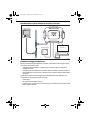
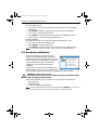
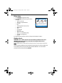
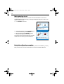
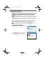
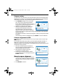
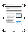
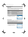
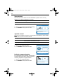
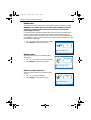
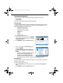
81287_1.book Page i Tuesday, March 18, 2008 11:50 AM
ST70 Autopilot
Controller
SmartPilot X
Commissioning
Instructions
Document reference: 81287-1
Date: March 2008
81287_1.book Page ii Tuesday, March 18, 2008 11:50 AM
ii
81287_1.book Page iii Tuesday, March 18, 2008 11:50 AM
Contents
iii
Contents
Chapter 1:Before you begin ..................................................................................... 1
1.1 Commissioning overview ............................................................................... 1
Commissioning pre-requisites ........................................................................ 2
Commissioning process ................................................................................. 3
1.2 Certified installation ....................................................................................... 3
1.3 Further assistance ......................................................................................... 3
1.4 Product documents ........................................................................................ 4
Chapter 2:15 ................................................................................................................. 5
Chapter 2:Commissioning procedures ................................................................ 5
2.1 Switching on and initial setup ......................................................................... 5
Switch on ........................................................................................................ 6
Initial setup ..................................................................................................... 7
2.2 Dockside calibration ....................................................................................... 9
Drive setup ................................................................................................... 10
Rudder check ............................................................................................... 10
Motor phasing check..................................................................................... 12
Dockside calibration complete ...................................................................... 12
2.3 Seatrial calibration ....................................................................................... 13
Begin Seatrial calibration .............................................................................. 13
Compass swing ............................................................................................ 14
Compass alignment to GPS.......................................................................... 14
Manual compass alignment .......................................................................... 14
Autolearn...................................................................................................... 15
2.4 After commissioning .................................................................................... 15
EMC Conformance ....................................................................................... 15
Chapter 3:Check and adjust settings ................................................................. 17
3.1 Introduction .................................................................................................. 17
3.2 Vessel settings ............................................................................................. 17
Setting Vessel Type ...................................................................................... 17
Drive type ..................................................................................................... 17
Auto release (mechanical stern drive only) ................................................... 17
Cruise speed ................................................................................................ 18
3.3 Drive / rudder settings .................................................................................. 18
Rudder gain.................................................................................................. 18
Counter rudder ............................................................................................. 19
Rudder damping ........................................................................................... 19
Auto trim ....................................................................................................... 20
Auto turn (motor boats only).......................................................................... 20
Response level ............................................................................................. 21
Off course alarm ........................................................................................... 21
Turn rate limit ................................................................................................ 22
Joystick control ............................................................................................. 22
Latitude compass damping........................................................................... 22
Rudder limit .................................................................................................. 23
Rudder offset ................................................................................................ 23
Reverse rudder reference............................................................................. 23
3.4 Sailboat settings .......................................................................................... 24
AutoTack ...................................................................................................... 24
81287_1.book Page iv Tuesday, March 18, 2008 11:50 AM
iv
Gybe inhibit................................................................................................... 24
Wind selection .............................................................................................. 25
WindTrim ...................................................................................................... 25
3.5 Dealer Calibration options ............................................................................ 26
Chapter 4:Maintenance & Troubleshooting ..................................................... 27
4.1 Maintenance ................................................................................................ 27
Servicing and safety ..................................................................................... 27
Instrument Cleaning ..................................................................................... 27
Cabling ......................................................................................................... 27
4.2 Troubleshooting ........................................................................................... 28
First considerations ...................................................................................... 28
Procedures ................................................................................................... 28
Troubleshooting tools ................................................................................... 32
Technical support.......................................................................................... 33
Glossary ..................................................................................................................... 35
81287_1.book Page v Tuesday, March 18, 2008 11:50 AM
v
Preface
Warnings and cautions
WARNING: Product installation & operation
Equipment must be installed, commissioned and operated in
accordance with the Raymarine instructions provided. Failure to
do so could result in personal injury, damage to your boat and/or
poor product performance.
CAUTION:
Before commissioning the SmartPilot X system, check that
individual components are the correct voltage for your boat’s
supply.
As correct performance of the boat’s steering is critical, we
STRONGLY RECOMMEND that an Authorized Raymarine
Service Representative commissions this product. You will only
receive full warranty benefits if you can show that an Authorized
Raymarine Service Representative has installed or commissioned
this product.
WARNING: Electrical safety
The power supply must be switched off before making any
adjustments to system hardware: components or cabling.
WARNING: Navigational safety
Although Raymarine designs all its products to be accurate and
reliable, many factors can affect product performance. Raymarine
products should serve only as an aid to navigation and should
never replace commonsense and navigational judgement. Always
maintain a permanent watch so you can respond to situations as
they develop.
81287_1.book Page vi Tuesday, March 18, 2008 11:50 AM
vi
Electromagnetic Compatibility (EMC) conformance
Raymarine equipment and accessories conform to the appropriate Electromagnetic
Compatibility (EMC) regulations for use in the recreational marine environment
Correct installation is required to ensure that EMC performance is not compromised.
EMC guidelines
Raymarine equipment and accessories conform to the appropriate Electromagnetic
Compatibility (EMC) regulations. This minimizes electromagnetic interference
between equipment, which could otherwise affect the performance of your system.
Correct installation is required to ensure that EMC performance is not compromised.
For optimum EMC performance, we recommend that:
•
•
•
•
Raymarine equipment and the cables connected to it are:
• At least 3 ft (1 m) from any equipment transmitting or cables carrying radio signals e.g. VHF radios, cables and antennas. In the case of SSB radios, the distance should be increased to 7ft (2m).
• More than 7 ft (2 m) from the path of a radar beam. A radar beam can normally
be assumed to spread 20 degrees above and below the radiating element.
The product is supplied from a separate battery from that used for engine start.
This is important to prevent erratic behavior and data loss which can occur if the
engine start does not have a separate battery.
Raymarine specified cables are used.
Cables are not cut or extended unless doing so is detailed in the installation manual.
Remember
Where constraints on the installation prevent any of the above recommendations.
always allow the maximum separation possible between different items of electrical
equipment. This will provide the best conditions for EMC performance for the
installation.
Suppression ferrites
Raymarine cables may be fitted with suppression ferrites. These are important for
correct EMC performance. Any ferrite removed to facilitate installation must be
replaced in the original position immediately installation is complete.
Use only ferrites of the correct type, supplied by Raymarine authorized dealers.
Connections to other equipment
If Raymarine equipment is to be connected to other equipment using a cable not
supplied by Raymarine, a Raymarine suppression ferrite MUST always be attached
to the cable near the Raymarine unit.
81287_1.book Page vii Tuesday, March 18, 2008 11:50 AM
Preface
vii
EMC conformance
Always check the installation before going to sea to make sure that it is not affected by
radio transmissions, engine starting etc.
To do this:
1. Turn on all transmitting equipment (radar, VHF radio etc.).
2. Check that all electronic systems are unaffected by the transmitting equipment
(e.g. without undue interference).
Compass
The compass is sensitive to magnetic influences and other potential sources of
interference including engines and VHF radio waves. To ensure optimum operation it
is essential to locate the compass correctly. For detailed instructions refer to the
separate installation information supplied with the compass.
To the best of our knowledge, the information in the product documents was correct
when they went to press. However, Raymarine cannot accept liability for any
inaccuracies or omissions in product documents.
In addition, our policy of continuous product improvement may change specifications
without notice. Therefore, Raymarine cannot accept liability for any differences
between the product and the accompanying documents.
Product disposal
Waste Electrical and Electronic (WEEE) Directive
The WEEE Directive requires the recycling of waste electrical and electronic
equipment.
Whilst the WEEE Directive does not apply to some of Raymarine's products,
we support its policy and ask you to be aware of how to dispose of this product.
The crossed out wheelie bin symbol, illustrated above, and found on our products
signifies that this product should not be disposed of in general waste or landfill.
Please contact your local dealer, national distributor or Raymarine Technical
Services for information on product disposal.
81287_1.book Page viii Tuesday, March 18, 2008 11:50 AM
viii
81287_1.book Page 1 Tuesday, March 18, 2008 11:50 AM
Chapter 1: Before you begin
1
Chapter 1: Before you begin
To achieve proper and reliable commissioning of your SmartPilot X system,
installation and commissioning must be carried out by a competent professional.
WARNING: Commissioning requirement
For proper control of your boat, you MUST commission your SmartPilot X
system using the instructions contained in this guide. Failure to do this
could cause poor product performance which could result in personal injury
and/or damage to your boat, unreliable course keeping and erratic behavior.
1.1 Commissioning overview
Commissioning is an essential procedure following installation, consisting of a series
of dockside safety checks and a seatrial calibration. Use this manual to guide you
through the commissioning procedure for a newly installed SmartPilot X system with
an ST70 autopilot controller. (For ST70 operating principles, refer to your ST70 Pilot
Controller User Reference Guide).
If your autopilot system has previously been commissioned successfully and has an
existing ST70 autopilot controller, you do not need to repeat the commissioning
process, unless you wish to recalibrate your system.
Note: To commission an SmartPilot X system using a SmartPilot controller (ST6002, ST7002,
ST8002), refer to the SmartPilot Series Commissioning Guide (part no. 81273).
81287_1.book Page 2 Tuesday, March 18, 2008 11:50 AM
2
SPX SmartPilot system with ST70 autopilot controller
SmartPilot System - key components
SmartPilot computer
ST70 controller
SMARTPILOT
CANCEL
X10
ENTER
MENU
Fluxgate compass
Drive unit
Rudder position sensor (optional)
D10927-1
Commissioning pre-requisites
Before commissioning the SmartPilot X system, check that the following processes
have been carried out correctly:
•
Autopilot system installation completed in accordance with the SmartPilot X
Installation Guide.
• SeaTalkng network installed in accordance with the SeaTalkng Reference Manual.
• GPS installation and connections carried out in accordance with the GPS installation guide.
Check also that the commissioning engineer is familiar with the installation and
components of the autopilot system including:
•
•
•
Vessel type.
What the autopilot will be used for.
System layout: components and connections (you should have a schematic of the
boat’s autopilot system).
81287_1.book Page 3 Tuesday, March 18, 2008 11:50 AM
Chapter 1: Before you begin
3
Commissioning process
•
•
•
•
•
Check you have adhered to commissioning pre-requisites.
Initial setup: switch on, system settings.
Dockside calibration.
Seatrial calibration.
SmartPilot X system ready for use.
1.2 Certified installation
Raymarine recommends certified installation by a Raymarine approved installer. A
certified installation qualifies for enhanced warranty benefits. (See the separate
warranty card packed with your product.) For more information on certified installation
contact your Raymarine dealer or refer to the Raymarine web site:
www.raymarine.com.
1.3 Further assistance
Comprehensive customer support is available online and by telephone.
www.raymarine.com
In the Customer Service area you will find:
•
•
•
•
Frequently Asked Questions (FAQs).
Servicing information.
Email access to the Raymarine Technical Support Department.
Details of Raymarine agents worldwide.
Telephone helpline
In the USA
+1 603 881 5200 extension 2444
In the UK, Europe, the Middle East or the Far East
+44 (0) 23 9271 4713 (voice)
+44 (0) 23 9266 1228 (fax)
Help us to help you
When requesting service, please quote as much of the following product information
as possible:
•
•
•
•
Product type
Model number
Serial number
Software issue number
81287_1.book Page 4 Tuesday, March 18, 2008 11:50 AM
4
1.4 Product documents
The following documents are available from www.raymarine.com/handbooks to
help you install and operate an autopilot system based around the SPX SmartPilot:
Document
Part number
SmartPilot X Commissioning Instructions (this docu- 81287-1
ment). Following installation, this document, which is
supplied with your autopilot controller, must be used to
correctly commission your autopilot system before it can
be used.
SmartPilot X System Installation Guide. Professional
installers should use this guide to ensure effective
installation/set up of a SmartPilot X system.
87071-1
SeaTalkng Reference Manual. This provides detailed
information regarding SeaTalkng connectivity.
81300-1
ST70 Pilot Controller User Reference Guide. Supplied 81288-1
with the ST70 autopilot controller.
Product installation guides. Separate installation
sheets are provided with individual components of the
autopilot system including the compass, rudder reference sensor, controller and drive
To the best of our knowledge, the information in the product documents was correct
when they went to press. However, Raymarine cannot accept liability for any
inaccuracies or omissions in product documents.
In addition, our policy of continuous product improvement may change specifications
without notice. Therefore, Raymarine cannot accept liability for any differences
between the product and the accompanying documents.
81287_1.book Page 5 Tuesday, March 18, 2008 11:50 AM
Chapter 2: Commissioning procedures
5
Chapter 2: Commissioning procedures
WARNING: Calibration requirement
All autopilot systems must be calibrated before use.
This chapter will guide you through the commissioning process for an SmartPilot X
system. It includes:
• Initial setup.
• Dockside calibration.
• Seatrial calibration.
The ST70 Autopilot Controller has an initial setup and calibration wizard, which will
take you through the commissioning process. Your autopilot will select the setup
screens relevant to your system. Those that are not relevant will be skipped
automatically.
Note: If you already have an ST70 instrument installed, some settings will be automatically
transferred from that and the wizard will skip those settings.
2.1 Switching on and initial setup
With the boat safely tied up, use these initial setup instructions to switch on the
autopilot system and controller, and to carry out the following initial setup procedures:
•
•
•
•
•
Select language.
Set boat type.
Set date and time format (only if GPS is fitted).
Set correct local time (only if GPS is not fitted).
Set required data units.
Note: In order to carry out calibration procedures you must complete initial setup.
If the system has previously been set up and calibrated this part of the setup wizard
will not be displayed and you can continue immediately with dockside calibration.
81287_1.book Page 6 Tuesday, March 18, 2008 11:50 AM
6
Switch on
1. Once you are sure the SmartPilot X system has been installed correctly in
accordance with the SmartPilot X installation guide, switch on the main power
breaker.
2. Switch on the ST70 autopilot controller by holding down the On/Standby button
for 1 second.
TRACK
+1
--1
STANDBY
AUTO
--10
CANCEL
MENU
+10
D10821-1
DODGE
ENTER
On/Standby button
3. If the SmartPilot X and ST70 autopilot controller are active, the ST70 will display
the Select Language menu.
Language
Troubleshooting
•
If the display is blank, check the fuse/circuit
breaker and the SeaTalkng fuse in the
SmartPilot X computer.
If the display shows the SEATALKNG FAIL or
NO DATA alarm message, check the
SeaTalkng connections.
English (UK)
Press ENTER to select
D9342-1
•
81287_1.book Page 7 Tuesday, March 18, 2008 11:50 AM
Chapter 2: Commissioning procedures
7
Initial setup
Select language
Use < and > to select the required language, then press ENTER to display the
‘Welcome’ screen. When you are ready to proceed, press ENTER to display the Set
Vessel Type screen.
Select Vessel Type
The Vessel Type menu enables you to automatically apply the optimum settings for
your boat type. The options are:
• Race Sail
• Sail Cruiser
• Catamaran
• Workboat
• RIB
• Outboard Speedboat
• Inboard Speedboat
• Power Cruiser 1 (up to 12 Kts)
• Power Cruiser 2 (up to 30 Kts)
• Power Cruiser 3 (30 Kts+)
• Sport Fishing
• Pro Fishing
Advanced Options
Vessel Type
Press ENTER to select.
D10840-1
1. Use < and > to select the boat type that is most
appropriate to your vessel.
2. When you have chosen the boat type, press
ENTER to confirm the choice.
If your system is receiving GPS information, a
Time & Date summary page is displayed next. If
your system is not receiving GPS information, the
next screen you will see will be Data units (see
Data units on page 8) unless you already have an
ST70 instrument installed.
Time & Date
If necessary, you can set the format of the date and time:
• You can select either DD/MM/YY or MM/DD/YY as the date format
• You can select either 12-hour (am/pm) or 24-hour as the time format.
With the Time & Date summary page displayed, check the date and time, then press
ENTER to display the Time & Date setup menu.
1. At the Time & Date setup menu, use < and > to
select the Set date format option, then press
ENTER, to display the Set date format page.
2. Use < and > to select the required Date
Format, then press ENTER, to save the format
and return to the Time & Date setup menu.
Display Settings
Time & Date
Change the default time and
i date settings.
Press ENTER to select.
D10838-1
Set date format
To set the required date format:
81287_1.book Page 8 Tuesday, March 18, 2008 11:50 AM
8
Set time format.
To set the required time format:
1. At the Time & Date setup menu, use < and > to select the Time Format option, then
press ENTER, to display the Set time format page.
2. Use < and > to select the required Time Format, then press ENTER, to save the
format and return to the Time & Date setup menu.
Set local time
To set the pilot controller time to your local time:
1. At the Time & Date setup menu, use < and > to select the Set time offset option,
then press ENTER, to display the Set time offset page.
2. Use < and > to set the correct local time. For example, if your local time is 1 hour
after GMT, set +1, then press ENTER, to save the setting and return to the Time &
Date setup menu.
Leaving date & time setup
When your date and time formats and values are set as required:
1. Display the Time & Date setup menu.
2. Use < and > to select the Continue option.
3. Press ENTER, to proceed to the Units summary page which shows the units
currently in use.
Units
Speed
KTS
You can set the units you want to use for displaying
Distance
NM
Depth
FT
data. You can set:
KTS
Wind Speed
• Speed: miles per hour, kilometers per hour or
Heading
M
Flow Rate
G/H
knots.
o
Temperature
C
• Depth: feet, fathoms or meters.
These are your current settings.
i
• Distance: either miles, nautical miles or
kilometers.
Press ENTER to continue
• Wind speed: knots or meters per second.
• Heading: magnetic or true.
• Temperature: degrees Celsius or degrees Fahrenheit.
• Flow rate: gallons per hour or liters per hour.
• Number of engines from 1 to 5.
• No of batteries from 1 to 5.
• Pressure: pounds per square inch, bar, or kilo pascal.
• Volume: liters, UK gallons or US gallons.
• Number of fuel tanks from 1 to 5.
When you are ready to proceed:
1. Press ENTER to display the second Units summary page.
2. Press ENTER again, to display the Units menu.
D9439-1
Data units
81287_1.book Page 9 Tuesday, March 18, 2008 11:50 AM
Chapter 2: Commissioning procedures
9
To set the required units:
1. Use < and > to select the type of data you want to change, i.e. Speed, Depth,
Distance etc.
2. Press ENTER, to display the setup page for the units you have selected.
3. Use < and > to select the required units.
4. Press ENTER, to save the units setting and return to the Units setup menu.
5. Repeat steps 1 to 4 for all data types you want to set.
Leaving units setup
When all units are set to your preferences, display the Units menu, then:
1. Use < and > to select the Continue option.
2. Press ENTER, to complete initial setup.
3. Press ENTER to leave Initial Setup and proceed to the first calibration page.
Note: If necessary, the initial setup values can be changed later, via the Main Menu.
2.2 Dockside calibration
Dockside Calibration
Before you can use
your autopilot you
need to do some
dockside checks.
Press CANCEL to
exit without saving.
If the system has already been calibrated but you
Press ENTER to continue.
wish to repeat the process, you can run the Setup
Wizard from the Advanced Options menu, accessible from the main menu.
D10886-1
When the initial setup is complete, the ST70
autopilot controller will determine whether the
SmartPilot X has been calibrated. If it has, you may
begin to use your ST70 immediately. If not, the on
screen wizard will then take you through the
calibration process, starting with dockside
calibration.
WARNING: Ensure proper control
For proper control of your boat, you MUST complete the dockside checks
before starting the initial seatrial.
With the boat still safely tied up, use these dockside calibration instructions to:
•
•
•
Set up the drive.
Check the rudder.
Check motor phasing (test the drive).
Note: You may exit the calibration process at any time by pressing CANCEL on your ST70 con-
troller. The next time you power up, you will be prompted to complete calibration.
81287_1.book Page 10 Tuesday, March 18, 2008 11:50 AM
10
1. Press ENTER to begin drive setup
Drive Type
2. Press ENTER to select drive type from the
following:
• Type 1 or 2 linear
• Type 2 or 3 hydraulic linear
Type 1 Linear
• I/O stern
Please select your boat's drive
i type.
• IPS
• Jet drive (pump or fly-by-wire)
Press ENTER to select.
• Wheel drive
• Tiller
• CR solenoid
• Sport drive
• Type 1 or 2 rotary
• Type 1, 2 or 3 hydraulic pump
• Constant running pump
• Verado
If you drive type is not listed, contact your Raymarine dealer for advice.
D10888-1
Drive setup
Rudder check
WARNING: If no rudder reference has been fitted you MUST ensure that
adequate provision is made to prevent the steering mechanism from
impacting the end stops.
Note: Systems without a rudder reference will skip this section and go straight to seatrial calibration.
This procedure establishes port and starboard rudder limits. Fine-tuning adjustments
to the rudder position may be made during seatrial calibration. You can exit this
procedure at any time by pressing CANCEL.
81287_1.book Page 11 Tuesday, March 18, 2008 11:50 AM
Chapter 2: Commissioning procedures
i
Turn the wheel hard to STARBOARD and
press ENTER. Press CANCEL to exit.
Press ENTER to accept.
2. When prompted, turn the rudder hard to port
and press ENTER.
Rudder Check
i
Turn the wheel hard to PORT and press
ENTER. Press CANCEL to exit.
Press ENTER to accept.
3. When prompted, center the wheel and press
ENTER.
D10902-1
Rudder Check
D10900-1
ENTER.
Rudder Check
i
Centre the rudder and press ENTER.
Press CANCEL to exit.
Press ENTER to accept.
D10895-1
1. Turn the rudder hard to starboard and press
11
81287_1.book Page 12 Tuesday, March 18, 2008 11:50 AM
12
Motor phasing check
The system will check the drive connection from the SmartPilot X. Once it has
completed the check successfully, a message will appear asking if it is safe for the
system to take the helm.
1. Press ENTER to continue.
Motor Check
Press ENTER to continue.
Rudder Check
i
Has rudder moved to PORT? Press
CANCEL if it has moved to STARBOARD.
Press ENTER to accept.
Dockside calibration complete
Once you have completed all the dockside setup, checks and calibration, you may
take your boat out to an area of calm water to commence seatrial calibration.
D10907-1
2. If the rudder moves to port, press ENTER. If it
moves to starboard, press CANCEL.
3. When prompted, press ENTER to confirm
that the motor phase is now correct.
The system now knows which signals to send the
rudder control for turns to port and starboard.
D10891-1
Is it safe to take the helm?
i Press CANCEL to exit.
81287_1.book Page 13 Tuesday, March 18, 2008 11:50 AM
Chapter 2: Commissioning procedures
13
2.3 Seatrial calibration
WARNING: Ensure you have sufficient sea room for calibration. The seatrial
calibration manoeuvres require a clear, familiar area of water. Ensure you
are not likely to collide with any vessel or other obstruction during
calibration.
WARNING: Maintain sensible speeds. The autopilot may make unexpected
turns.
CAUTION: Sailing vessels should perform the sea trial under engine power.
When the dockside setup and calibration procedures are complete, navigate to a
place where you have plenty of sea room, then carry out the seatrial calibration
procedures to complete the SmartPilot X system commissioning.
Note: You may exit the calibration process at any time by pressing CANCEL on your ST70 con-
troller. The next time you power up, you will be prompted to complete calibration.
Begin Seatrial calibration
1. Press ENTER to begin seatrial calibration.
Sea Trial Calibration
Press CANCEL to exit
without saving.
Press ENTER to continue.
Sea Trial Calibration
3.) Press ENTER to begin compass calibration.
IMPORTANT!
STANDBY
You can press
STANDBY at any time
to take over the helm.
Press ENTER to continue.
D10904-1
2.) Press ENTER for standby warning message.
D10903-1
Before you can use your
autopilot you need to do
some open water checks.
The water must be calm
with light wind.
Leave plenty of room
to manouevre.
81287_1.book Page 14 Tuesday, March 18, 2008 11:50 AM
14
Compass swing
You will need to turn your boat in slow circles while the system automatically makes
adjustments to account for compass deviation. Each 360-degree circle should take
no less than two minutes, and you should complete at least two circles.
D10882-1
1. Press ENTER and begin to turn your boat in
Compass Calibration
slow, even circles. Keep speed to below 2
knots. Watch the display to ensure you are not
OK
turning too fast. If the message ‘Slow Down’ is
displayed you will need to slow down.
2. When the compass has been calibrated, a
Move in a slow circle.
message will be displayed showing the
i Press CANCEL to exit.
detected deviation. If this is more than 5
Press ENTER to start.
degrees you will need to abort the calibration
process and resite the compass further away from metal items, then repeat the
calibration process.
If you still find a deviation of more than 5 degrees, contact your Raymarine dealer
for advice.
If the deviation is within acceptable limits, press ENTER to continue calibration.
Compass alignment to GPS
Note: Systems without a GPS will skip this section and go straight to Manual compass align-
ment on page 14.
If your system has a GPS connected to your data network (SeaTalk, SeaTalkng or
NMEA), the autopilot is tuned to the GPS heading while you steer to a known
magnetic heading. This step provides a rough alignment and minimizes the amount of
compass fine tuning required.
Align to GPS
OK
i
Steer the boat on a steady course.
Press CANCEL to exit.
Press ENTER to continue.
D10875-1
1. When the vessel has performed sufficient
turns to complete compass linearization, the
following display should be shown.
2. Steer the boat on steady course and
accelerate to more than 3 knots.
3. Follow the on-screen instructions until the
screen displays the ‘OK’ message, then press
ENTER to continue.
Manual compass alignment
Compass Alignment
220°
Use +1 and -1 buttons to adjust
i the heading.
Press ENTER to accept.
D10874-1
1. Continue to steer on a steady course and use
the Use +1 and -1 buttons to adjust the heading
displayed until it matches the ship’s compass
reading.
2. Press ENTER to continue.
81287_1.book Page 15 Tuesday, March 18, 2008 11:50 AM
Chapter 2: Commissioning procedures
15
Autolearn
The next stage of calibration requires the autopilot to learn the vessel’s steering
characteristics. This will require the pilot to execute a number of maneuvers.
CAUTION: You must have significant clear water in front of the boat to
accommodate a series of maneuvers, which include sudden, sharp turns.
There should be a clear area at least 100m wide and 500m ahead.
Autolearn
Press ENTER to continue.
4. Press ENTER to finish calibration and return to
manual helm.
5. Pilot enters STANDBY
You have successfully completed the
commissioning process for your SmartPilot X
system.
2.4 After commissioning
Autolearn
STANDBY
i
The vessel will zigzag and make SUDDEN SHARP
TURNS.
Press AUTO to continue.
D10878-1
1. Press AUTO to continue.
2. Maintain a normal cruising speed (at least 3
knots).
3. During this procedure a number of messages
will appear. Simply follow the prompts to
complete the procedure. Ensure that ‘PASS’ is
displayed signalling the completion of
autolearn.
D10876-1
The next stage of calibration
requires the Autopilot to
learn the vessel's steering
characteristics. This will
require the pilot to execute
a number of manouevres.
Please ensure there is a free
area of water 100m wide by
500m in front of the vessel.
Autolearn
PASS
i YOU HAVE THE HELM.
Press ENTER to continue.
D10877-1
1. Ensure there is sufficient free water in front of
the vessel.
2. Press ENTER to continue.
Before using the autopilot system you should familiarize yourself with its functions
and ensure you know how to use it correctly. It is important to:
• Read the user documentation supplied with your ST70 pilot controller
• Trial the system in familiar waters away from other vessels and obstructions
CAUTION: Any additional changes you make to your system settings may
require you to repeat the calibration process. Refer to the ST70 Pilot
Controller User Reference Guide for more information.
EMC Conformance
Always check the installation before going to sea to make sure that it is not affected by
radio transmissions, engine starting etc.
81287_1.book Page 16 Tuesday, March 18, 2008 11:50 AM
16
81287_1.book Page 17 Tuesday, March 18, 2008 11:50 AM
Chapter 3: Check and adjust settings
17
Chapter 3: Check and adjust settings
3.1 Introduction
Many installations will require fine tuning. If you are a professional installer, ensure
you check the autopilot settings before handing the system over to the customer.
3.2 Vessel settings
You can adjust the following vessel settings to more accurately reflect your boat’s
particular setup and what you will be using your autopilot system for.
Setting Vessel Type
CAUTION: Vessel Type determines other parameters
If you change the Vessel Type, you must then ensure all other parameters
are set as you require before using the boat, as some other parameters
change when the Vessel Type changes.
The vessel type options will normally give optimum performance for typical vessels of
each type. However, you may find you can improve the performance of your vessel by
selecting an option for a different vessel type.
1. At the Advanced Options menu, use < and > to select Vessel Type, then press
ENTER to display the Vessel Type menu.
2. Use < and > to select the required Vessel Type, then press ENTER to save and
exit the menu.
Refer to Select Vessel Type on page 7 for more details.
Drive type
Refer to Drive setup on page 10 for more details.
Auto release (mechanical stern drive only)
1. Use < or > to switch auto release on or off.
2. Press ENTER to accept the new value.
Auto Release
On
i Enable/Disable auto release.
Press ENTER to select.
D10879-1
.Auto release allows you to override the pilot by
taking hold of the wheel or tiller. When you release
the wheel or tiller, the pilot will return to the last
locked heading.
81287_1.book Page 18 Tuesday, March 18, 2008 11:50 AM
18
Cruise speed
1. Use < or > to increase or decrease the cruising
speed.
2. Press ENTER to accept the new value.
Cruising Speed
15 KTS
i Set boat cruise speed.
Press ENTER to select.
3.3 Drive / rudder settings
D10885-1
Set the cruise speed to the boat’s typical cruising
speed. If no speed data is available, the SmartPilot
system will use the cruise speed value you set
here as a default when adjusting autopilot settings.
CAUTION: Adjustments to the drive and rudder settings will require you to
recommission the system.
You may be able to improve steering and autopilot performance by making
adjustments to the following settings:
Rudder gain
Rudder gain is a measure of how much helm the SmartPilot X will apply to correct
course errors. The higher the setting the more rudder will be applied. The rudder gain
setting is set automatically as part of the Autolearn process (see Autolearn on
page 15).
.
Screen Text
Range
Rudder Gain
1 to 9
Rudder Gain
1. Use < or > to increase or decrease the amount
of gain.
2. Press ENTER to accept the new value.
4
Defines the amount of rudder applied to
correct the vessel's course.
Press ENTER to select.
D10897-1
i
81287_1.book Page 19 Tuesday, March 18, 2008 11:50 AM
Chapter 3: Check and adjust settings
19
Counter rudder
Counter rudder is the amount of rudder the SmartPilot X system applies to try to
prevent the boat from yawing off course. Higher counter rudder settings result in more
rudder being applied.
Screen Text
Range
Counter Rudder
1 to 9 (Do NOT set to 0)
The default counter rudder gain is set as part of the
initial seatrial Autolearn process.
Counter Rudder
1. Use < or > to increase or decrease the setting.
2. Press ENTER to accept the new value.
5
Press ENTER to select.
D10884-1
The rate of return of the rudder
i once on the new heading.
Rudder damping
On SmartPilot X systems with a rudder reference transducer, you can set the rudder
damping to prevent autopilot ‘hunting’. Increasing the rudder damping value reduces
hunting. When adjusting the value, increase the damping one level at a time until the
autopilot stops hunting. Always use the lowest acceptable value.
.
Screen Text
Range
Rudder Damping
1 to 9
Rudder Damping
1. Use < or > to increase or decrease the setting.
2. Press ENTER to accept the new value.
2
Press ENTER to select.
D10896-1
Prevents the rudder from
i oscillating.
81287_1.book Page 20 Tuesday, March 18, 2008 11:50 AM
20
Auto trim
The AutoTrim setting determines the rate at which the SmartPilot X system applies
‘standing helm’ to correct for trim changes caused by varying wind loads on the sails
or superstructure.
The default AutoTrim is set as part of the Autolearn process.
Setting
Effect
OFF
No trim correction
1 to 6
Auto trim applied:
1 = Slowest, 6 = Fastest
D10880-1
If you need to change the setting, increase the
Auto Trim
AutoTrim one level at a time and use the lowest
acceptable value:
1
• If the SmartPilot X system gives unstable
course keeping or excessive drive activity with
a change in the heel angle, decrease the
The amount of standing rudder
AutoTrim level.
i applied to compensate for wind drift.
• If the SmartPilot X system reacts slowly to a
Press ENTER to select.
heading change due to a change in the heel
angle, increase the AutoTrim level.
• If the AutoTrim level is too high, the boat will be less stable and snake around the
desired course.
1. Use < or > to increase or decrease the setting.
2. Press ENTER to accept the new value.
Auto turn (motor boats only)
Auto Turn
1. Use < or > to increase or decrease the setting.
2. Press ENTER to accept the new value.
90
i
Define the course change when
performing an Auto Turn.
Press ENTER to select.
D10881-1
This setting defines the amount of course change
when performing an auto turn.
81287_1.book Page 21 Tuesday, March 18, 2008 11:50 AM
Chapter 3: Check and adjust settings
21
Response level
This sets the default SmartPilot X system response level setting. The response level
controls the relationship between course keeping accuracy and the amount of helm/
drive activity. You can make temporary changes to response during normal operation
(see the ST70 Pilot Controller User Reference Guide for details).
Setting
Options
Levels1 to 3
Minimize the amount of pilot activity. This conserves power, but may
compromise short-term course-keeping accuracy
Levels 4 to 6
Should give good course keeping with crisp, well controlled turns
under normal operating conditions
Levels7 to 9
give the tightest course keeping and greatest rudder activity (and
power consumption). This can lead to a rough passage in open waters
as the SPX system may ‘fight’ the sea.
Response Level
1. Use < or > to increase or decrease the setting.
2. Press ENTER to accept the new value.
5
Press ENTER to accept.
D10894-1
Response level increases pilot
i activity.
Off course alarm
This screen determines the angle used by the OFF COURSE alarm (see your ST 70
Operating Guide). The OFF COURSE alarm operates if the pilot strays off course by
more than the specified angle for more than 20 seconds.
Screen Text
Range
Off Course Alarm
15° to 40° in 1° steps
Off Course Alarm
1. Use < or > to increase or decrease the setting.
2. Press ENTER to accept the new value.
i
Define the course error at which an
alarm is sounded.
Press ENTER to accept.
D10892-1
15
81287_1.book Page 22 Tuesday, March 18, 2008 11:50 AM
22
Turn rate limit
This limits your boat’s rate of turn under SmartPilot X system control. It is only
effective if your speed is greater than 12 knots.
Screen Text
Range
Turn Rate
1° to 30° per second in 1° steps
Turn Rate Limit
1. Use < or > to increase or decrease the setting.
2. Press ENTER to accept the new value.
i
Sets the maximum rate of turn
under pilot control.
Press ENTER to accept.
Joystick control
D10905-1
5
Note: This is not available on SeaTalkng. Joystick operation is available only with an ST8002
control head or Joystick connected via SeaTalk.
Setting
Effect
Proportional
The steering will behave in proportion to the movement of the joystick
or rotary wheel on an ST8002 control head.
Bang Bang
Will move the rudder hard over in the direction the joystick is moved.
1. Use < or > to change the setting.
2. Press ENTER to accept the new value.
Joystick Control
i Select Joystick control mode.
Latitude compass damping
If no valid latitude data is available, the SmartPilot
X system will use this setting, which provides the
necessary adaptation for higher latitudes.
Press ENTER to select.
D10893-1
Bang Bang
Latitude Compass Damping
On
i Set cruising latitude.
Press ENTER to select.
D10889-1
1. Use < or > to change the setting.
2. Press ENTER to accept the new value.
81287_1.book Page 23 Tuesday, March 18, 2008 11:50 AM
Chapter 3: Check and adjust settings
23
Rudder limit
The rudder limit screen is displayed only if a rudder reference transducer is fitted.
WARNING: If no rudder reference has been fitted you MUST ensure that
adequate provision is made to prevent the steering mechanism from
impacting the endstops.
If a rudder reference transducer is fitted, this screen is used to set the limits of the
rudder control just inside the mechanical end stops, and thus avoid putting the
steering system under unnecessary load. This should be set when commissioning
the SmartPilot X system. The limit should be set to approximately 5 degrees less than
the maximum rudder angle.
1. Use < or > to increase or decrease the setting.
2. Press ENTER to accept the new value.
Rudder Limit
i Sets the rudder limit.
This specifies the offset from amidships (zero
adjustment).
1. Use < or > to increase or decrease the setting.
2. Press ENTER to accept the new value.
Press ENTER to select.
Rudder Offset
0
i Sets the rudder offset.
Press ENTER to select.
D10899-1
Rudder offset
D10898-1
20
Reverse rudder reference
1. Use < or > to change the setting.
2. Press ENTER to accept the new value.
Reverse Rudder Reference
Port
i Reverses the rudder.
Press ENTER to select.
D10901-1
This reverses the phase of the rudder reference
display.
81287_1.book Page 24 Tuesday, March 18, 2008 11:50 AM
24
3.4 Sailboat settings
These settings are only applicable to sailboats
AutoTack
The Auto Tack Angle feature allows you to specify the angle through which the vessel
will tack when you select Auto Tack. When in Wind Vane mode, this will match
Apparent Wind Angle.
1. Press MENU, then use < and > to scroll to Autopilot Calibration and press
ENTER.
2. Use < and > to scroll to Vessel Settings and press ENTER.
3. Use < and > to scroll to Sailboat Settings and press ENTER.
4. Use < and > to scroll to Auto Tack Angle and
Auto Tack Angle
press ENTER.
5. Use < and > to increase or decrease the auto
90
tack angle.
6. Press ENTER to accept the change or CANCEL
to exit without making any changes.
Press ENTER to select.
D10860-1
Auto Tack sets the angle that the
i vessel will tack through.
Gybe inhibit
1. Press MENU, then use < and > to scroll to
Gybe Inhibit
Autopilot Calibration and press ENTER.
2. Use < and > to scroll to Vessel Settings and
Disable
press ENTER.
3. Use < and > to scroll to Sailboat Settings and
press ENTER.
Stops an accidental gybe.
i
4. Use < and > to scroll to Gybe Inhibit and press
ENTER.
Press ENTER to select.
5. Use < and > to enable or disable gybe inhibit.
6. Press ENTER to accept the change or CANCEL to exit without making any
changes.
D10856-1
With gybe inhibit on, to prevent accidental gybes, the SmartPilot will prevent the boat
from performing an AutoTack away from the wind
With gybe inhibit off, you can perform an AutoTack into or away from the wind. See
also AutoTack on page 24.
81287_1.book Page 25 Tuesday, March 18, 2008 11:50 AM
Chapter 3: Check and adjust settings
25
Wind selection
Note: Only available if wind data is available.
Wind Selection
Press ENTER to select.
D10855-1
1. Press MENU, then use < and > to scroll to
Autopilot Calibration and press ENTER.
2. Use < and > to scroll to Vessel Settings and
press ENTER.
3. Use < and > to scroll to Sailboat Settings and
press ENTER.
4. Use < and > to scroll to Wind Selection and
press ENTER.
5. Use < and > to switch between True and Apparent.
6. Press ENTER to accept the change or CANCEL
to exit without making any changes.
Sailboat Settings
Wind Selection
True
i
Select wind source.
Press ENTER to select.
WindTrim
D10854-1
This option determines whether the boat steers to
apparent or true wind in Wind Vane mode.
WindTrim controls how quickly the SmartPilot X system responds to changes in the
wind direction. Higher wind trim settings will result in a system that is more responsive
to wind changes.
Sailboat Settings
Press ENTER to select.
D10853-1
Wind Trim
Wind Trim
5
Controls the sensitivity of the
i pilot when steering to wind.
Press ENTER to select.
D10852-1
1. Press MENU, then use < and > to scroll to
Autopilot Calibration and press ENTER.
2. Use < and > to scroll to Vessel Settings and
press ENTER.
3. Use < and > to scroll to Sailboat Settings and
press ENTER.
4. Use < and > to scroll to Wind Trim and press
ENTER.
5. Use < and > to increase or decrease the auto
tack delay.
6. Press ENTER to accept the change or CANCEL
to exit without making any changes.
81287_1.book Page 26 Tuesday, March 18, 2008 11:50 AM
26
3.5 Dealer Calibration options
Note: Use the table below to note down your calibration settings so you can easily reference to
Calibration Lock
Vessel Type
Drive Type
Rudder Alignment
OFF, ON
DISPLACE, SEMI DISPLACE, PLANING,
STERN DRV, WORK BOAT, SAIL BOAT
3, 4, 5
: -9 to +9
Rudder Limit
10 to 40
Rudder Gain
1 to 9
Counter Rudder
1 to 9
Rudder Damping
1 to 9
AutoTrim
0 to 4
Response: Gyro
Non-G
1 to 9
1 to 3
Turn Rate Limit
1 to 30
Off Course Angle
15 to 40
Power Steer
(Joystick)
OFF, 1, 2
AutoRelease
OFF, ON
AutoTack Angle
40 to 125
Gybe Inhibit
OFF, ON
Wind Type
APPARENT, TRUE
Wind Trim
1 to 9
Cruise Speed
4 to 60
AutoAdapt
OFF, nth, Sth
Latitude
0 to 80
Variation
-30 to +30
Autopilot Reset
OFF, ON
Sail Boat
Work Boat
Stern
Drive (I/O)
Planing
SemiDisplacement
Displacement
Vessel type
Factory
Default
them (if required).
Your
Settings
81287_1.book Page 27 Tuesday, March 18, 2008 11:50 AM
27
Chapter 4: Maintenance & Troubleshooting
4.1 Maintenance
Servicing and safety
Unless specific instructions are given to the contrary, Raymarine equipment should
be serviced only by authorized Raymarine service technicians. They will ensure that
service procedures and replacement parts used will not affect performance.
Some products generate high voltages, so never handle the cables/connectors when
power is being supplied to the equipment.
When powered up, all electrical equipment produces electromagnetic fields. These
can cause nearby electrical equipment to interact, with a possible adverse effect on
operation. To minimize these effects and enable best possible performance from your
Raymarine equipment, guidelines are given in the installation instructions.
Always report any EMC-related problem to your nearest Raymarine dealer. We use
such information to improve our quality standards.
In some installations, it may not be possible to prevent the equipment from being
affected by external influences. In general this will not damage the equipment but it
can lead to spurious resetting action, or momentarily may result in faulty operation.
Instrument Cleaning
Periodically clean your ST70 pilot head with a soft damp cloth.
Do NOT use chemical or abrasive materials to clean your pilot head.
Do NOT wipe the pilot head with a dry cloth as this could cause scratches.
Cabling
Periodically examine all cables for chafing or other damage to the outer shield, and
where necessary, replace and re-secure
81287_1.book Page 28 Tuesday, March 18, 2008 11:50 AM
28
4.2 Troubleshooting
In the unlikely event that you encounter problems using your ST70 pilot head, use this
section to resolve the situation.
First considerations
If your ST70 is not performing as you think it should, be sure you are operating
correctly as described in the ST70 Pilot Controller User Reference Guide, supplied
with the pilot head.
Then:
• Ensure that any data you think may be missing, is available on your boat. For
example, if you do not have a wind transducer, then there will be no wind-related
data.
• Take into account any changes that may have been made to the electrical system
aboard your boat. Such changes could affect the performance of your ST70 pilot
head.
• Be aware that radio signals transmitted nearby (for example from another boat or
shore station) could affect the performance of your ST70 pilot head.
If you are satisfied that the problem is not due to any of the above, use the procedures
in this section to isolate the cause of the problem.
Procedures
If an ST70 pilot head appears not to be operating satisfactorily, check the symptoms
below to determine how to resolve the problem:
•
•
•
•
Nothing on the pilot head screen - refer to Figure 4-1 on page 29
Data missing from the pilot head screen - refer to Figure 4-2 on page 30
Data on the pilot head screen is garbled- refer to Figure 4-3 on page 31
Specific data types are missing or incorrect:
• Check the relevant Transducer and Pod, including connections between them
and to the system.
• If speed readings are missing or obviously wrong, the speed transducer paddle wheel could be fouled and need cleaning.
81287_1.book Page 29 Tuesday, March 18, 2008 11:50 AM
Chapter 4: Maintenance & Troubleshooting
29
ST70 user troubleshooting
Nothing on
screen
Chart 1
Are the pilot buttons
back-lit?
NO
YES
Is power on at any other
product in the system?*
* The system to which the pilott is connected (either SeaTalk,
2
ng
SeaTALK or SeaTalk
)
NO
YES
Switch on power to the
system
At faulty pilot, carry out
switch-on procedure
Is problem still
present?
Are the pilot buttons
back-lit?
NO
YES
NO
Return to
normal
operation
YES
Is the display lit?
Ensure all system
connections are made
satisfactorily
NO
Check display brightness
setting and adjust as
necessary (see Operating
Guide)
Is the display lit?
YES
Is problem still
present?
Return to
normal
operation
NO
YES
NO
Use the About Display & About
System features to get
information about your products.
Return to
normal
operation
Figure 4-1 ST70 troubleshooting – Chart 1
Obtain
technical
assistance
Return to
normal
operation
D9524-1
YES
81287_1.book Page 30 Tuesday, March 18, 2008 11:50 AM
30
ST70 user troubleshooting
Chart 2
Data missing
Is the display lit?
Refer to Chart 1
NO
YES
Are some data types
present?
NO
YES
At 'suspect' pilot, run
the About System
diagnostic function
Are the same data
types missing from
more than one product
in the system?
Is resultant product list
empty?
NO
YES
NO
Ensure all system
connections are
satisfactory.
YES
Ensure connections to
'suspect' pilot head are
satisfactory.
Ensure connections to
relevant transducer(s)
and pod(s)are
satisfactory.
Is data present?
Is all data available?
NO
NO
YES
Use the About Display & About
System features to get
information about your products.
Return to
normal
operation
Obtain
technical
assistance
Figure 4-2 ST70 troubleshooting – Chart 2
Use the About Display & About
System features to get
information about your products.
Return to
normal
operation
Obtain
technical
assistance
D9526-1
YES
81287_1.book Page 31 Tuesday, March 18, 2008 11:50 AM
Chapter 4: Maintenance & Troubleshooting
31
ST70 user troubleshooting
Garbled information
on screen
Chart 3
Are other instruments
in system working OK?
NO
YES
Ensure all system
connections are
satisfactory.
Is problem still
present?
NO
YES
Obtain
technical
assistance
Figure 4-3 ST70 troubleshooting – Chart 3
Return to
normal
operation
D9529-1
Use the About Display & About
System features to get
information about your products.
81287_1.book Page 32 Tuesday, March 18, 2008 11:50 AM
32
Troubleshooting tools
Your ST70 pilot head has the following in-built user diagnostic functions:
• About Display
• About System
Use these as appropriate to help isolate problem areas.
About Display
3. Use < or > to select the About Display option,
About Display
then press ENTER.
Software Ver.
V0.07
Hardware Ver.
V0.21
4. The About Display information is displayed.
Bootcode Ver.
V0.19
Make a note of the data you need then press
Temperature
29.72 C
Volts
14.20
V
ENTER:
Peak Volts
14.74 V
Current
• If you have seen all the available data the
165 mA
Peak Current
221 mA
display shows the Diagnostics menu.
Run Time
18.45
• If there is more data to be displayed, the
Press ENTER to continue.
next page of About Display data is displayed. Repeat step 4 until the display shows the Diagnostics menu.
About System
The About System function provides a list of products on the system and a serial
number for each product.
To run the About System function:
1. With the Diagnostics menu displayed, use < or > to select the About System
option.
2. Press ENTER to display the Diagnostics menu.
D10939-1
Press ENTER to select.
D10095-1
The About Display function provides information about the pilot head on which it is
run. Before seeking technical assistance, please use the About Display function
whenever possible to find out the relevant:
• Software Version Number
• Hardware Version Number
• Bootloader Version Number
• Temperature
• Voltage
• Current
• Total hours run
To run the About Display function:
Main Menu
1. With the pilot head switched on, press MENU to
display the Main Menu, then use < or > to select
the Diagnostics option.
2. Press ENTER to display the Diagnostics menu.
Diagnostics
81287_1.book Page 33 Tuesday, March 18, 2008 11:50 AM
Chapter 4: Maintenance & Troubleshooting
33
3. Use < or > to select the About System option, then press ENTER.
4. The About System information is displayed. Make a note of the data you need then
press ENTER:
• If you have seen all the available data the display shows the Diagnostics
menu.
• If there is more data to be displayed, the next page of About Display data is displayed. Repeat step 4 until the display shows the Diagnostics menu.
Technical support
Raymarine provides a comprehensive customer support service, on the world wide
web and by telephone help line. Please use either of these facilities if you are unable
to rectify a problem.
If you intend seeking technical assistance, please first use the About Display and
About System functions whenever possible, and make a note of the information
available there.
Note: If it is not possible to use the About Display function on a faulty instrument, remember you
may still be able to get system information by running About System at another instrument.
World wide web
Please visit the Customer Support area of our web site at:
www.raymarine.com
As well as providing a comprehensive Frequently Asked Questions section and
servicing information, the web site gives e-mail access to the Raymarine Technical
Support Department and a details of the locations of Raymarine agents, worldwide.
Telephone help line
If you do not have access to the world wide web, please call the Raymarine help line.
In the USA, call:
• +1 603 881 5200 extension 2444
In the UK, Europe the Middle East or the Far East, call:
• +44 (0) 23 9271 4713 (voice)
• +44 (0) 23 9266 1228 (fax)
Help us to help you
When requesting service, please have the following product information to hand:
• Equipment type.
• Model number.
• Serial number.
• Software version.
• Hardware version.
You can find out this information by running the About Display and About System
diagnostic functions.
81287_1.book Page 34 Tuesday, March 18, 2008 11:50 AM
34
81287_1.book Page 35 Tuesday, March 18, 2008 11:50 AM
35
Glossary
Abbreviation
Description
AWA
Apparent Wind Angle
AWS
Apparent Wind Speed
COG
Course Over Ground
EMC
Electromagnetic Compatibility
NGCC
New Generation Course Computer
SOG
Speed Over Ground
ST
SeaTalk
ST2
SeaTALK2
STNG
SeaTalk New Generation / SeaTalkng
STW
Speed Through Water
TWA
True Wind Angle
TWS
True Wind Speed
81287_1.book Page 36 Tuesday, March 18, 2008 11:50 AM
36
ST70 User Reference Manual
81287_1.book Page 37 Tuesday, March 18, 2008 11:50 AM
37
Specification
Supply voltage:
Nominal12 V dc
Maximum16 V dc
Minimum 10 V dc
Absolute maximum: 18.5 V dc
Current:
Nominal – dependent on screen brightness setting
Maximum – not more than 220 mA
Dimensions (excluding studs) 4.33 in W x 4.53 in H x 1.28 in D (110 mm x 115 mm x 32.5 mm)
Connections
Two SeaTalkng
Operating temperature
-20º to +70ºC
Illumination
Sliding scale
Compliances
RoHS
EMC EN60945 Revision 4
Buzzer
Monotone buzzer (3.9 kHz)
81287_1.book Page 38 Tuesday, March 18, 2008 11:50 AM
38
ST70 User Reference Manual
81287_1.book Page 39 Tuesday, March 18, 2008 11:50 AM
39
Index
A
G
About Display, 32
About System, 32
Alarm
off course, 21
Apparent wind angle, 25
Auto release, 17
Auto trim, 20
Auto turn, 20
Gybe inhibit, 24
C
Language, 7
Latitude damping, 22
Local time, 8
Cleaning, 27
Commissioning, 1
Commissioning
dockside setup
data units, 8
date format, 7
language, 7
local time, 8
time format, 8
vessel type, 7
pre-requisites, 2
procedure, 5
process, 3
requirement, 5
Compass
alignment to GPS, 14
calibration, 14
latitude damping, 22
Counter rudder, 19
Cruise speed, 18
D
Data units, 8
Date format, 7
Disposing of the product, vii
Dockside calibration, 9
Dockside setup
data units, 8
date format, 7
language, 7
local time, 8
time format, 8
vessel type, 7
Documentation, 4
E
EMC conformance, 15
EMC information, vi
H
Help lines, 33
I
Initial setup, 5, 7
L
O
Off course alarm, 21
P
Power steer, 22
Product disposal, vii
R
Response level, 21
Reverse rudder reference, 23
Rudder
counter rudder, 19
damping, 19
gain, 18
limit, 23
offset, 23
reverse reference, 23
S
Safety, 27
electrical, v
general, v
navigation, v
Servicing, 27
Setup
data units, 8
date format, 7
initial, 7
local time, 8
select language, 7
select vessel type, 17
time format, 8
vessel type, 7
Speed
cruising, 18
Switching on and off, 5
81287_1.book Page 40 Tuesday, March 18, 2008 11:50 AM
40
T
V
Technical support, 33
Time
local, 8
Time and date
setting, 7
Time format, 8
Troubleshooting, 28
charts, 28
symptoms, 28
data missing from screen, 29
garbled information, 30
nothing on screen, 28
Technical support, 33
using About Display, 32
using About System, 32
True wind angle, 25
Turn rate limit, 22
Vessel type, 7, 17
W
Wind selection, 25
Wind trim, 25