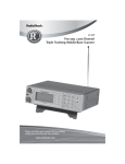
1
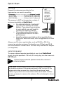
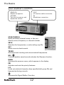
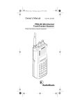
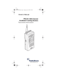
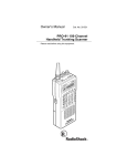
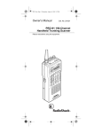
20-433
PRO-433 1,000 ch Trunking
Desktop/Mobile Scanner
Thank you for purchasing your PRO-433 1,000 Channel Trunking
Desktop/Mobile Scanner from RadioShack. Your scanner is one of
a new generation of scanners designed to track Motorola® Type I,
Type II, hybrid analog, and many other systems.
Quick Start
p. 4- 10
Scanner
DC cable with fuse
DIN sleeve
Mounting bracket
Lock washers (2)
Rubber feet (4)
Preprogrammed frequency sheet
Please read this user’s guide before installing,
setting up and using your new scanner.
www.radioshack.com
AC adapter
Antenna
Removal keys (2)
Knobs (2)
Screws (2)
User’s guide
Contents
quick start
4
step 1: installing your scanner
step 2: power your scanner
step 3: connect your scanner
step 4: setting up your scanner
step 5: monitoring and scanning
the basics
4
5
6
8
10
11
your scanner’s controls
your scanner’s display
replacing the fuse
12
13
15
beyond the basics
16
channel-storage banks
priority channels
chain search
service bank search
weather search and alert
FIPS codes
Skywarn
Signal Stalker I
data skip
keytones
delay
memory lock
16
16
17
18
18
19
20
21
22
23
23
23
trunking operations
24
programming trunked frequencies
talk group ID
AFS Format
talk group ID search range (EDACS)
Status Bit (S-Bit) Ignore
trunk search and scan
2
24
25
28
28
29
30
Contents
type I and hybrid trunked systems
programming base and offset frequencies
Motorola disconnect tone detect function
30
33
34
special features
35
PC programming
scanner cloning
35
35
care
37
troubleshooting
resetting the scanner
service and repair
37
38
38
specifications
39
RF emissions information
40
limited one-year warranty
40
3
Quick Start
quick start
step 1: installing your scanner
You can mount your scanner as a base station or in your vehicle. If
you are unsure how to install your scanner in your vehicle, consult
your automobile manufacturer, dealer, or a qualified installer.
base station
Attach the four protective rubber feet to the mounting bracket
when you use the scanner as a base station on a flat surface such
as a desk, shelf, or table. Because the speaker is on the bottom
of the scanner, you can use the mounting bracket to elevate your
scanner off the surface for better sound.
vehicle mounting
To mount your scanner under or over the dashboard, use the
mounting bracket. Before installing, confirm that your scanner
fits in the desired mounting area and you have all the necessary
materials to complete the task.
IMPORTANT: AVOID AIRBAG DEPLOYMENT ZONES. This can
prevent the airbag from performing properly and result in injury.
1. Use the supplied mounting bracket as a template to mark
positions for the two mounting screws.
2. At the marked positions, drill holes slightly smaller than the
screws. When drilling holes, be sure to avoid obstructions and
wires behind the mounting surface.
3. Attach the mounting bracket to the surface using the supplied
screws.
4. Slide the scanner into the bracket, aligning the scanner’s holes
with the holes in the bracket, and then screw the mounting
knobs into the scanner.
4
Quick Start
Your scanner requires a 2 x 7-1/8 x 5-5/16 inch (50 x 180 x 135
mm) mounting area. Allow an additional 2-3/8 inch (60 mm) space
behind the scanner for connectors and wires.
1. Remove the four rear screws that secure the outer metal case
and pull off the case with care.
2. Insert the DIN sleeve into the opening in your dashboard, lip
facing out.
3. Push out the top and bottom tabs to hold the sleeve firmly in
place.
4. Slowly slide the scanner into the sleeve until it locks in place.
• When mounting in your dashboard, you will need to
NOTES
•
connect an external antenna and an external speaker.
To remove your scanner from the DIN sleeve, insert the
two removal keys straight into the scanner’s front panel
and pull the scanner out.
step 2: power your scanner
You can power your scanner from a wall outlet, through your
vehicle’s ignition, or from your vehicle’s cigarette lighter or power
port. You must use a Class 2 power source that supplies 12V DC
and delivers at least 500mA. Its center tip must be set to positive
and its plug must fit the scanner’s DC 12V jack. Using an adapter
that does not meet these specifications could damage the scanner
or the adapter.
DC 12V
Power source connection.
wall outlet
To prevent electric shock,
do not use the AC adapter’s
polarized plug with an
extension cord, receptacle,
or other outlet unless you
can fully insert the blades.
1. Connect the tip of the supplied AC adapter to the DC 12V jack.
2. Plug the AC adapter into your wall outlet.
5
Quick Start
vehicle cigarette lighter or power port
To power your scanner from your vehicle’s 12V power source,
use a 12V DC cigarette-lighter adapter (not supplied, available at
RadioShack).
NOTE
If you use a cigarette-lighter adapter, you might hear some
electrical interference from your engine while scanning.
This is normal.
vehicle ignition (negative ground only)
NOTE
If you are not experienced in connecting accessories to
the vehicle fuse box, use a certified installer.
1. Disconnect the cable from the negative (-) terminal of your
vehicle’s battery.
2. Ground the black wire of the supplied DC power cord to your
vehicle’s chassis. The grounding screw must make complete
contact with the metal frame of your vehicle.
3. Connect the red wire of the supplied DC power cord to a
voltage source that turns on and off with the ignition switch,
such as a spare accessory terminal in your vehicle’s fuse box.
4. Insert the adapter’s barrel plug into the scanner’s DC 12V jack.
5. Reconnect the cable to the negative (-) terminal of your
vehicle’s battery.
step 3: connect your scanner
ANT
Antenna connection.
EXT SP
External speaker connection.
6
Quick Start
antenna
Expand the antenna according to the
frequencies you want to montitor:
Frequency ..................................... Antenna Length
25-174 MHz .....................Extend fully (4 segments)
400-512 MHz ................... Extend half (2 segments)
806-1300 MHz ................Collapse fully (1 segment)
The scanner’s ANT jack supports a variety of
antennae (available at RadioShack).
•
NOTES
•
•
ANT
Match the
antenna
connector
arrow to
the ANT
jack’s upper
projection.
An external antenna is optional if
you use your scanner as a base
station. If you mount your scanner
in your vehicle, you will need to
connect an external antenna.
The antenna should be as high
as possible and vertical for best
performance.
Keep the antenna and cable as far as possible from
sources of electrical noise, such as appliances or other
radios.
Always use 50-ohm coaxial cable, such as RG-58 or RG-8, to
connect an outdoor antenna. For lengths over 50 feet, use RG-8
low-loss dielectric coaxial cable. You also may need a BNC adapter
(not supplied).
external speaker
To use an external speaker (available at your local RadioShack
store), plug the speaker’s 1/8 inch (3.5 mm) plug into the scanner’s
EXT SP jack.
NOTE
Connecting an external speaker mutes the scanner’s
internal speaker.
CAUTION: Use extreme caution when installing or removing
an outdoor antenna. If the antenna starts to fall, let it go! If the
antenna touches a power line, touching the antenna, mast,
cable, or guy wires can cause electrocution and death. Call the
power company to remove the antenna. Do not attempt to do so
yourself.
7
Quick Start
step 4: setting up your scanner
turning on your scanner
To turn on your scanner, turn the VOLUME knob clockwise
until it clicks. To set the squelch, turn the SQUELCH knob fully
counterclockwise, then rotate it clockwise until the hissing sound
stops.
storing frequencies in channels
Your scanner comes with 150 preprogrammed frequencies. You
can manually store frequencies using a frequency guide such as
the “RadioShack Police Call Guide including Fire and Emergency
Services, and Official Aeronautical Frequency Directory.”
1. Press E/PGM. PGM appears in the display.
2
Enter the channel number where you want to store a frequency.
3. Press SCAN/MANUAL.
4. Enter the frequency including the decimal point.
5. Press E/PGM to store the frequency. The scanner automatically
rounds the entered number to the nearest valid frequency. For
example, 151.473 (MHz) becomes 151.475.
NOTE
If you entered a frequency that is already saved on
another channel, the scanner beeps and displays the
channel. Press . /CLR /DELAY to exit, or press E/PGM to
store the frequency on both channels.
copying / moving frequencies
To copy or move a frequency, complete the following steps:
1. Press or
to select the channel that contains the frequency,
and press E/PGM.
2. Press and hold E/PGM. The scanner copy/move menu appears.
3. Press or
to select Copy or Move, then press E/PGM.
8
Quick Start
4. Select the target bank. The smallest empty channel number
flashes over the frequency.
5. Press or
to access the target channel.
6. Press E/PGM. If there is no empty channel, the scanner
automatically selects the first channel of the bank.
To cancel the copy or move, press . /CLR /DELAY.
searching for frequencies
You can search for frequencies up or down using direct search.
1. Press and hold SRCH. SRCH appears in the display.
2. (Optional) To set a starting frequency, press HOLD and enter
the frequency.
3. Press or
to begin searching up or down the frequencies.
4. (Optional) To avoid unwanted frequencies, you can skip up to
200 specified frequencies during a search. To skip a frequency,
press L/O when the scanner finds the frequency.
•
NOTES
•
•
You cannot skip frequencies during a weather service
search.
If you skip all frequencies within the search range, the
scanner cannot search.
If you try to skip more than 200 frequencies, the
scanner will stop skipping the earliest skipped
frequencies.
To clear a skipped frequency, complete the following steps:
1. Press HOLD/RESUME to stop the search.
2. Select the frequency. L/O appears.
3. Press L/O. L/O disappears.
4. (Optional) To clear all the skipped frequencies, press HOLD/
RESUME, then hold down L/O until the scanner beeps twice.
9
Quick Start
step 5: monitoring and scanning
monitoring
To monitor a channel, press SCAN/MANUAL while the scanner is
pausing on the channel, or stop the scanning by pressing SCAN/
MANUAL, enter the channel number, and press SCAN/MANUAL.
scanning
To scan, press SCAN/MANUAL. When the scanner finds a
transmission, it monitors the transmission until it ends.
•
NOTES
•
If you have not stored frequencies into any channels,
the scanner cannot scan.
If the scanner picks up weak transmissions, turn
SQUELCH clockwise to decrease the scanner’s
sensitivity to these signals. To listen to a weak or
distant station, turn SQUELCH counterclockwise.
Press SCAN/MANUAL to stop scanning, or press HOLD/RESUME
to pause the scan without losing your position.
earphones / headphones
For private listening, you can plug earphones or headphones into
your scanner’s headphone jack. Do not use headphones with your
scanner when operating a motor vehicle in or near traffic. Doing so
can create a traffic hazard and could be illegal in some areas. Some
headphones let you hear some outside sounds when listening at
normal volume levels, but they still can present a traffic hazard.
To protect your hearing, follow these guidelines for headphones.
•
•
•
Do not listen at extremely high volume levels. Extended highvolume listening can lead to permanent hearing loss.
Set the volume to the lowest setting before you begin listening,
then adjust the volume to a comfortable level.
After you set the volume, do not increase it. Over time, your
ears adapt to the volume level, so a volume level that does not
cause discomfort might still damage your hearing.
10
The Basics
the basics
A frequency is the tuning location of a station. A channel is a
programmable memory location for storing frequencies that
you can scan for activity. Channels are grouped into 10 channelstorage banks, each of which contains 100-channels. Service banks
are preset channel-storage banks of frequencies used by HAM
operators, marine, aircraft, and police (fire/emergency) services.
For example, many amateur radio frequencies are located in the
HAM service bank.
Your scanner provides many features that help you locate,
monitor, and organize useful transmissions in your area, including
frequencies used by police and fire departments, ambulance
services, government agencies, private companies, amateur
radio services, military operations, pager services, and wireline
(telephone and telegraph) service providers.
This scanner is designed to prevent reception of illegal
transmissions, in compliance with laws that require that scanners
be manufactured to not be easily modifiable to pick up those
transmissions. Do not open your scanner’s case to make any
modifications that could allow it to pick up transmissions that it is
not legal to listen to. Doing so could subject you to legal penalties.
It is legal to listen to almost every transmission your scanner can
receive. However, there are some transmissions you should never
intentionally listen to. These include:
•
•
•
telephone conversations (cellular, cordless, or other private
means of telephone signal transmission)
pager transmissions
any scrambled or encrypted transmissions
According to the Electronic Communications Privacy Act (ECPA),
as amended, you are subject to fines and possible imprisonment
for intentionally listening to, using, or divulging the contents of
such a transmission unless you have the consent of a party to the
communication (unless such activity is otherwise illegal).
We encourage responsible, legal scanner use.
11
The Basics
your scanner’s controls
SQUELCH
Adjusts the squelch.
PC/IF
PC interface cable connection.
VOLUME
Turns on the scanner and
adjusts the volume.
Headphone connection.
SCAN/MANUAL
Starts and stops channel scans, or lets you
directly enter a frequency or channel number.
SRCH
Searches for frequencies, or active talk group IDs.
SVC
Starts a service bank search.
TRUNK
Accesses trunk tracking and stores trunked frequencies.
WX /
Controls weather searches and activates the Skywarn function.
MENU
Accesses the scanner menu, which appears in the display.
PRI
Activates and sets the priority features.
L/O
Locks out selected channels, skips specified talk group IDs and
frequencies during a search.
Accesses the Signal Stalker I function.
12
The Basics
Number keys
Enter a channel, a frequency, or an ID number.
HAM
Selects the ham band when in service mode.
MRN
Selects the marine band when in service mode.
AIR
Selects the air band when in service mode.
POL
Selects the police band when in service mode.
ALERT
Activates the NWR-SAME weather alert.
CLR /DELAY
Clears error messages, or accesses the delay feature.
E/PGM
Stores frequencies into channels, and programs the trunking
frequency, fleet map, and ID memories.
DM/M-LOCK
Lets you set the display brightness, or locks the
memory. To set the brightness of the display
backlight select BRIGHT, DIMMER or OFF.
or
Searches or scans up and down, or selects options.
HOLD /RESUME
Stops and resumes searching.
your scanner’s display
BANK
Indicates active channel-storage banks
(1–10) or talk group ID lists (trunking).
TRUNK
Appears during trunking operations.
P
Indicates priority channels and talk
groups.
13
The Basics
DATA
Appears when the data skip function is active, and in the trunking
mode when the dis connect tone detect function is off.
Appears when Signal Stalker I is active.
SCAN
Appears during channel scan.
LIST
Appears with numbers (1–5) during trunking. A bar indicates which
ID scan list banks are turned on for scanning.
SRCH
Appears during chain, direct, and ID searches.
SVC
Appears during Service Search mode.
PRI
Appears when the priority feature is turned on.
HOLD
Appears during chain, direct, service, and ID searches, and ID
monitor holds, and flashes while the scanner is temporarily
monitoring a programmed ID.
DLY
Appears when you select a Delay option.
L/O
Appears when you manually select a locked out channel and talk
group.
M-LOCK
Appears when you select a memory lock option.
Appears when you select a Skywarn channel.
PGM
Appears while you store a frequency into a channel, enter a
frequency range during a chain search, or program trunking
frequencies, fleet maps, or ID memories while trunking.
14
The Basics
or
Indicates the search direction during a chain, direct, or service
search, and normal and weather scan.
ALERT
Appears when the weather alert is turned on, or flashes when the
scanner detects an alert coded signal.
M, E or L
Indicates the trunking system: Motorola (M), EDACS (E), or LTR (L).
CH
Indicates the current channel.
replacing the fuse
To replace your scanner’s fuse, turn off the scanner and your
vehicle’s ignition, then replace the fuse only with another fuse of
the same type and rating (1-amp, fast-acting glass fuse).
15
Beyond the Basics
beyond the basics
channel-storage banks
The scanner displays the channel-storage bank number while
scanning a channel. You can turn off a bank by pressing the bank’s
number, but one bank must always be active. To increase scanning
speed, you can lock out channels with continuous transmission,
such as weather channels or birdies. Birdies are internally
generated signals inherent in the electronics of the receiver. If your
scanner stops during scan mode and no sound is heard, it may be
receiving a birdie.
To lock out a channel, manually select the channel, then press L/O.
L/O appears in the display. To unlock a channel, press L/O when the
scanner stops on the channel or manually select the channel and
press L/O. L/O disappears. To unlock all channels in the banks that
are turned on, press HOLD/RESUME to stop scanning, then hold
down L/O until the scanner beeps twice.
NOTE
You can manually select locked-out channels.
priority channels
You can set one priority channel for each bank. The scanner checks
the current priority channel every 2 seconds. To activate the priority
feature, press PRI. PRI appears in the display. To turn off the priority
feature, press PRI again.
NOTE
If you have locked out all priority channels, CH Loc Out
appears when you activate the priority feature.
Each bank’s first channel is the priority channel by default. To
change a priority channel, complete the following steps:
1. Press E/PGM.
2. Enter the number for the priority channel, and press PRI. P
appears to the right of the selected channel number. Press PRI
to review all priority channels.
16
Beyond the Basics
chain search
Chain search lets you search through preset frequency ranges and
store found frequencies. You can also modify each range.
NOTE
At least one bank must be active. If you disable all the
banks, the error tone beeps.
1. Press SRCH. SRCH appears.
2. (Optional) Press 0 – 9 to enable / disable search banks:
Bank No.
Frequency (MHz)
Step (kHz)
1 ...................................................29.0000 – 54.0000 ..............................5
2 ..................................................137.0000 – 147.9950 ..........................5
3 ...................................................179.7500 – 215.7500 ....................6000
4 ...................................................216.0000 – 224.9950 ..........................5
5 ...................................................225.0000 – 399.9875 .....................12.5
6 ...................................................400.0000 – 449.99375 ...................6.25
7 ...................................................450.0000 – 469.99375 ...................6.25
8 ...................................................470.0000 – 512.0000 .....................6.25
9 ...................................................806.0000 – 956.0000 .....................12.5
10 .................................................1240.0000 – 1300.0000 .................12.5
3. Press or
to search up or down.
4. When the scan pauses, press HOLD/RESUME. To step through
the frequencies, press
or .
5. To save a frequency, press E/PGM. The bank numbers flash.
6. Enter the target bank number. The smallest empty channel
number flashes over the frequency.
7. Press or
to select to target channel.
8. Press E/PGM.
To program a search range, complete the following steps:
1. During a chain search, press and hold E/PGM. The lowest and
the highest frequencies of Bank 1 appear alternately.
2. Press the number of the bank you want to change. The lower
frequency range appears.
17
Beyond the Basics
3. Enter the lower limit frequency, and then press E/PGM.
4. Press or
to change to the upper limit frequency.
5. Enter the upper limit frequency, and then press E/PGM.
6. When you finish programming frequency ranges, press SRCH.
service bank search
You can search preprogrammed frequencies allocated to HAM,
marine, aircraft, or police (fire/emergency) transmissions. To use
service bank search, complete the following steps:
1. Press SVC. The most recently used service symbol appears
and the scanner starts searching.
2. To select a different service bank, press 1/HAM, 2/MRN, 3/AIR
or 4/POL. The selected service symbol appears.
3. Press or
NOTE
to search up or down.
It can take several minutes to search all the service
frequencies.
weather search and alert
The National Oceanic and Aerospace Administration (NOAA)
broadcasts Specific Area Message Encoding (SAME) alerts with
digitally-encoded data, including the alert severity. This scanner
detects SAME signals and displays the alert severity.
You cannot scan frequencies and monitor for weather alerts at the
same time. To start weather scan, complete the following steps:
1. Press WX. WX appears in the display.
2. Press or
to change the search direction.
3. To stop the search, press HOLD/RESUME. HOLD appears.
4. To set the weather alert, press 6/ALERT. ALERT appears. This
mutes the audio until the scanner receives a SAME alert.
18
Beyond the Basics
When the scanner receives a SAME-coded signal, ALERT flashes
one of the following codes to indicate the alert level:
L1... ................................................................................................. Warning
L2.. ...................................................................................................... Watch
L3... ................................................................................................ Advisory
WXA ...................................................................... Weather Alert (1050 Hz)
To activate tones for the alert levels, press WX to activate the
weather service, then hold down ALERT for about 1 second. Each
alert code appears as its tone sounds. Press any key to end the test
sequence.
FIPS codes
To limit weather alerts to specific areas, you can program FIPS
codes for those areas. The scanner can be set to either, alert for all
areas, or only the areas you have programmed.
SAME uses a standard established by the US Census bureau, called
FIPS. The format of a FIPS code is PSSCCC, where:
P ......................................................... area subdivision (0=entire area)
SS .................................................................State code (00=all states)
CCC ..................................................... County code (000=all counties)
For example, the FIPS code for Tarrant County, Texas is:
048439 (48=Texas; 439=Tarrant County)
1. During weather scan, press HOLD.
2. Press E/PGM. The scanner enters FIPS programming mode.
If the scanner is set to alert for all FIPS, ALLFIPS appears on
the display. If the scanner is set to alert only the area you have
programmed, F1 appears.
3. To set the scanner to scan all FIPS codes, press or
to move
ALLFIPS. Then press E/PGM. Then go to WX hold mode.
4. To program a FIPS code, press or
to select a displayed FIPS
code (F1 to F15), and enter the FIPS code using the numbered
keypad.
5. Press E/PGM to store the FIPS code. If an invalid value has
been inputted, the FIPS code is cleared.
19
Beyond the Basics
Skywarn
Skywarn jumps directly to the last channel in memory from any
mode. The scanner pauses any active scans and starts receiving
transmissions in the last channel. If no frequency is programmed in
the last channel, No Prog appears and the scanner sounds an error
tone.
During inclement weather, reports made by Skywarn observers
include information about:
•
•
•
•
•
•
•
•
•
•
•
•
pea-sized and larger hail
wind and wind gusts 40 MPH and greater
heavy rainfall
lightning (cloud-to-cloud and especially cloud-to-ground)
wall clouds (which can spawn tornadoes)
severe lowering of a wall cloud
turbulence in a wall cloud
funnel clouds
tornadoes
high water areas
downed power lines
other emergency conditions that affect life or property
Skywarn broadcasts can help you prepare for inclement weather
conditions in your immediate area, even before your local NOAA
weather broadcast and local TV or radio station can announce
them. Enter the local Skywarn frequency for your area into Channel
1000 on your scanner. Then, listen to Skywarn first when severe
weather threatens. Listen to NOAA for weather alerts and warnings,
watch box notices, and weather-forecasts. Listen to Skywarn to
hear trained observers in your vicinity call in official reports to a
net control station which relays those reports to NOAA and other
emergency agencies.
NOTE
If you tune to a Skywarn frequency when the Skywarn
net is not active, you may hear nothing, or you may
hear amateur radio operators talking on a local repeater
system.
20
Beyond the Basics
Signal Stalker I
Signal Stalker I searches for frequencies in a specified range.
This works well for locating strong local transmissions, such as
mobile and handheld two way radios in areas with no other strong
transmission sources; however, if you are in an area with many
transmission sources (such as pager radio transmitters, multiuse
radio towers, traffic control devices, etc.), Signal Stalker I may not
correctly display.
Signal Stalker I can work in the background while scanning other
frequencies and automatically saves strong signals to one of 10
log channels, located after Channel 1000. You can scan the log
channels along with the normal channels, or you can manually
access log channels as Channel 1001, Channel 1002, ... Channel
1010. “-1-”, “-2-”, ... “-10-” appear as channel numbers.
NOTES
•
•
Turn off the data skip feature if it is on.
You cannot program frequencies in the log channels.
The frequencies in the log channels are deleted when
you turn off the scanner.
To turn on Signal Stalker I, turn SQUELCH fully clockwise, then
press the Signal Stalker I button
appears in the display.
. The Signal Stalker I icon
To turn off Signal Stalker I, press the Signal Stalker I button
.
To set Signal Stalker I settings, complete the following steps:
1. Press MENU.
2. Press or
to select SIG-St., and press E/PGM. The Signal
Stalker I options appear.
3. Repeatedly press or
to select the option you want, then
press E/PGM.
S-S.bnd ................................................................................................Band
One of the following band names appears: 29-54, 108-137,
137-174, 179-320, 320-512, 806-956. Repeatedly press or
to select a band, then press E/PGM.
21
Beyond the Basics
S-S.ALt ................................................................................... Alert settings
S-S.Lit ............................................................................. Back light settings
S-S.PS ....................................................................... Pager screen settings
S-S.OnlY ...............................................................................Mode settings
To turn off normal scanning, when Signal Stalker I is
running, turn S-S.OnlY setting to ON.
S-S.Int .................................................................... Voice interrupt settings
To keep Signal Stalker I active while receiving an audio
signal, set this function to ON. If you turn this function
OFF, the scanner does not check signals while receiving
an audio signal.
S-S.LOG ............................................................................Logging settings
Set S-S.LOG to ON to scan the log channels along with the
normal channels.
4. For other settings, press or
to select ON or OFF, then press
E/PGM.
5. Press . /CLR /DELAY to exit the option mode.
6. Press MENU to exit the menu mode.
data skip
Data skip prevents the scanner from stopping on nonmodulated or
data signals (such as fax or modem transmissions) during a search
or scan.
NOTE
Data skip does not apply to the air band and weather
search mode, as data signals are not generally found in
these services.
To turn on the data skip feature, complete the following steps:
1. Turn off the priority feature if it is on.
2. Press MENU.
3. Repeatedly press or
4 . Press or
to display dAtA-S, then press E/PGM.
to select OFF or ON, then press E/PGM.
22
Beyond the Basics
5. Press MENU to exit the menu mode.
keytones
The keytones feature beeps when you press a button on the
scanner. To modify keytone settings, complete the following steps:
1. Press MENU.
2. Press or
to until bEEP appears in the display, then press
3. Press or
to select OFF or ON, then press E/PGM.
E/PGM.
4. Press MENU to exit the menu mode.
delay
When the delay feature is active, the scanner automatically
monitors channel frequency for an additional 2 seconds after a
transmission stops before resuming scanning or searching.
To access the delay, press . /CLR /DELAY while the scanner is
monitoring a channel, scanning, or searching. DLY appears when
the delay is active and disappears when inactive.
NOTE
Signal Stalker I also has a delay feature. It’s delay time
is 10 seconds. See “Signal Stalker I” for how to program
Signal Stalker I Delay.
memory lock
The memory lock feature protects the scanner from accidental
program changes.
To turn on the memory lock, hold down DM/M-LOCK until MLOCK appears. To turn it off, hold down DM/M-LOCK until M-LOCK
disappears. When the scanner is locked, it beeps an error tone if
you try to program a frequency or talk group ID.
NOTE
Using the memory lock does not prevent the scanner from
scanning channels.
23
Trunking Operations
trunking operations
The scanner can track transmissions for up to 10 Motorola Type I,
Type II, hybrid, EDACS or LTR analog trunking systems. When the
scanner finishes checking activity in the trunked system, it scans
other conventional frequencies in the bank.
For trunked reception, set the squelch at the center position. If set
too high, it could prevent your scanner from locking on the control
channel reliably. If it is set too low, it can delay finding the control
channel. The best setting is critical for monitoring trunked systems.
programming trunked frequencies
To program trunked frequencies, complete the following steps:
1. Press E/PGM in conventional mode to set the scanner in
programming mode. Then, press TRUNK. Your scanner beeps,
then all the bank numbers flash.
2. Press the number key for the desired target storage bank.
3. Press or
to select a trunking system type, then press
E/PGM. You can select from the following systems:
You See
Trunk System
E2 – 800 ........................................Motorola Type II, 800 MHz frequencies
E2 – 900 ........................................Motorola Type II, 900 MHz frequencies
E2 – Hi ........................ Motorola Type II, VHF (136-174 MHz) frequencies
E2 – UHF ..................... Motorola Type II, UHF (400-512 MHz) frequencies
E1 .................................................................. Motorola Type I, and Hybrid
Ed ............................................................. EDACS Wide Band: 9600 baud
Ed – SCt .................................................................................... EDACS Scat
Lt..... ........................................................................................................ LTR
4. Prog F appears, then press E/PGM. The scanner automatically
selects the first channel in the selected banks.
5. Use the number keys to enter a valid frequency within the trunk
system, then press E/PGM. The bank number, the channel
number, and E (EDACS), M (Motorola) or L (LTR) appears
depending upon the trunk system selected.
24
Trunking Operations
•
NOTES
•
For EDACS and LTR systems, you must enter the
frequencies in logical channel number (LCN) order.
If you try to enter a duplicate frequency in a bank, the
scanner beeps and the channel which was previously
stored appears.
6. Press or
to select the next channel in the bank and repeat
Step 4 to enter frequencies in that bank.
7. Press SRCH to begin searching for the trunk’s data channel
and scan conventional frequencies at the same time. After the
data channel is acquired, the scanner begins a trunk search that
finds all active talk groups in the trunked system.
8. (Optional) To turn a bank on or off, press and hold the SCAN/
MANUAL button during trunk scanning. When the trunked bank
appears, press the bank number (0–9).
talk group ID
Each trunk scanning bank contains ten talk group ID lists (with up to
10 talk group IDs each), for a total of 100 talk group IDs each. These
lists organize trunking system users into categories. For example,
you might use List 1 for police IDs, List 2 for fire department IDs,
and List 3 for emergency medical service IDs. After you store talk
group IDs in a list, you can scan them just as you scan conventional
channels.
NOTE
To locate talk group ID lists for your local police, fire, or
other agencies, refer to frequency guides available at your
local RadioShack store.
Storing talk group IDs
1. Select the trunking programming mode and the bank you want
to change.
2. Press or
to choose trunk system, and press E/PGM.
3. Press or
to choose Prog id, and press E/PGM.
4. Press or
to select the scan list location.
25
Trunking Operations
5. Enter the talk group IDs for each trunk system.
LTR talk groups are identified as six-digit numbers in the form
AHHUUU:
A ................................................................................Area code (0 to 1)
H .......................................................... Home repeater (01 through 20)
U ...................................................................User ID (000 through 254)
6. Press E/PGM.
scanning a talk group ID list
Press SCAN/MANUAL to begin scanning the lists you have stored.
If an ID is incorrect, Error flashes twice and the scanner beeps
several times, then the scan list numbers appear at the top of the
display. To correct the entry, delete the incorrect ID.
NOTE
One of the ten scan lists must always be active. You
cannot remove all of them.
To remove a scan list from active scanning, use the number keys to
enter the scan list’s number. The scan list number turns off, and the
IDs in that list are not scanned.
To restore a scan list to active scanning, use the number keys to
enter the number of the list again.
locking out a talk group ID
Many municipal and commercial services use trunk systems to
transmit signals from devices such as water-meter transmitters,
door alarms, and traffic signals. These are not voice signals, but are
assigned talk group IDs. To scan more efficiently, you can lock out
up to 100 talk group IDs.
To lock out an ID, press L/O when the ID appears. The ID is locked
out, and the next active ID appears. If you lock out an ID while
searching, it is also locked out of the scan list(s).
To unlock a single ID, complete the following steps:
1. Select the trunking programming mode and the bank you want
to review.
26
Trunking Operations
2. When the selected trunked system is displayed, press E/PGM.
3. Use or
to choose Id Lout, and press E/PGM.
4. Press L/O, the ID is unlocked and the next locked ID displays.
5. If you unlocked all locked IDs, the scanner displays Non.
To unlock all talk group IDs, hold L/O untill you hear two beeps.
priority talk group ID scanning
Your scanner checks priority IDs more frequently than the other
IDs. Each group ID list can have one priority ID, and the priority talk
group ID in List 1 has the highest priority of all.
To turn priority ID scanning on or off, press PRI during ID scanning
or manual operation. PRI appears when priority scanning is on.
To designate a priority ID, press and hold PRI. P appears.
NOTE
Priority ID scanning does not operate if the priority IDs are
locked out.
monitoring a talk group ID
Your scanner displays activity for talk group IDs. You cannot hear
conversations in this mode, but it is an excellent way to determine
which talk group IDs are the most active.
To monitor a talk group ID, complete the following steps:
1. Hold down SRCH until you hear two short beeps. SRCH
flashes, and all active group IDs appear in succession.
2. Press HOLD/RESUME. HOLD appears and the scanner stays on
the current ID.
3. If you want to listen to (and hold) a different ID, use the number
keys to enter that ID.
4. Press . HOLD flashes, then the scanner monitors the ID.
To stop monitoring the ID, press HOLD/RESUME.
27
Trunking Operations
AFS Format
Your scanner can translate decimal talk group lists to the much
more powerful AFS format. Become familiar with AFS partial entry,
and your scanning will become more flexible and efficient.
The AFS format allows you to enter full or partial EDACS IDs for
powerful flexibility in all modes.
1. Select the trunking programming mode and a bank.
2. Press or
to select EDACS, then press E/PGM.
3. Press or
to select AFS, then press E/PGM.
4. Press or
to select AFS ON or AFS OFF, then press E/PGM.
talk group ID search range (EDACS)
You can program a specific talk group such as 01-011 into the scan
list memory. In AFS mode, you can program the talk groups for an
entire agency by pressing corresponding keys.
You can set a range for agencies or fleet listings for the scanner’s
EDACS talk group ID search.
To set a search range, complete the following steps:
1. Press HOLD.
2. Use the number keys to enter the agency number. For example,
“01.”
3. (Optional) To search within a specific fleet, see the number keys
to enter the agency number. For example, “01.”
For example:
You Press
To Scan
01.E ......................................................................................... all 01 groups
01.01E ...........................................all 01 talk groups within the 01 agency
4. Press SRCH.
28
Trunking Operations
You can enter partial group numbers for EDACS talk groups. By
entering only the desired portion of a group, you can select either
128, 8, or 1 talk group. For example, you might program every talk
group in a police department by pressing just four keys.
NOTE
You cannot use partial talk groups in decimal mode.
To enter a partial EDACS ID:
1. Enter the agency number.
2. (Optional) To program all the talk group numbers for one fleet
of an agency, enter the fleet number.
3. Press E/PGM.
Status Bit (S-Bit) Ignore
Some systems use status bits to identify special situations. For
Motorola Type II systems, the last four bits of a talk group ID are the
status bits. Your scanner is preset to ignore status bits, but you can
set the scanner to interpret status bits.
NOTE
Important: For Motorola Type I systems, you might have
to turn off status bit ignore to determine the proper fleet
map. For other systems, turn on the status bit ignore or
you will miss some transmissions.
To set the status bit ignore feature, complete the following steps:
1. Set the scanner to conventional programming mode and then
press TRUNK.
2. Select the bank.
3. Press or
E/PGM.
to select the system type (Motorola), then press
4. Press
to select S-bit, then press E/PGM.
or
5. Press or
to select ON or OFF, then press E/PGM.
29
Trunking Operations
trunk search and scan
You can trunk scan and scan conventional frequencies at the same
time. You can program conventional frequencies in the same bank
as trunking systems, but not while in trunk mode.
To scan both trunking and conventional banks, turn off trunking,
select the banks to scan, then turn on trunking again.
To switch to trunk modes while scanning conventional frequencies,
complete the following steps:
1. Press TRUNK. The scanner begins scanning both trunking and
conventional banks.
2. Hold down TRUNK for about 1 second. The scanner switches
to the trunk scan mode.
3. Hold down TRUNK for about 1 second again. The scanner
switches to the trunk search mode.
To identify a trunked frequency while scanning or searching,
press . The frequency flashes twice. Then hold down until a
confirmation tone sounds and the ID and the frequency alternate.
To return to normal operation, press .
type I and hybrid trunked systems
Your scanner is preset to scan Type II system IDs. When you scan
trunked frequencies, each Type II user ID appears as an even
number without a dash (example 2160). Your scanner can also scan
Type I trunked systems. Each Type I ID appears as a three- or fourdigit number, followed by a hyphen, followed by a one- or two-digit
number (example 200-14).
•
NOTES
•
If you notice a mix of odd- and even-user IDs (examples
6477, 2160, 6481, 6144, and 1167), then you are
probably monitoring either a Type I or hybrid (a
combination of Type I and Type II user IDs) system with
the S-Bit function turned off.
If you consistently miss responses even with scan
delay, change your default system type or fleet map.
30
Trunking Operations
Subfleet information is included with the frequency list for a Type
I system. There are 16 preset fleet maps to choose from, and it is
best to start with these when setting up a Type I or hybrid trunk
scanning bank.
preset fleet maps
1. Set the scanner for conventional scanning and press E/PGM,
then press TRUNK to select the trunking programming mode
and the bank you want to change.
2. Repeatedly press or
to select TYPE 1 SYSTEM (E1), then
3. Repeatedly press or
to select FLEEt, then press E/PGM.
press E/PGM.
4. Repeatedly press or to select the name of the desired map
(example E1P7).
E1P1
Block Code
0
1
2
3
4
5
6
7
Size
S11
S11
S11
S11
S11
S11
S11
S11
E1P2
Block Code
0
1
2
3
4
5
6
7
Size
S4
S4
S4
S4
S4
S4
S4
S4
E1P3
Block Code
0
1
2
3
4
5
6
7
Size
S4
S4
S4
S4
S4
S4
S12
(S12)
E1P4
Block Code
0
1
2
3
4
5
6
7
Size
S12
(S12)
S4
S4
S4
S4
S4
S4
E1P5
Block Code
0
1
2
3
4
5
6
7
Size
S4
S4
S12
(S12)
S4
S4
S4
S4
E1P6
Block Code
0
1
2
3
4
5
6
7
Size
S3
S10
S4
S4
S12
(S12)
S12
(S12)
E1P7
Block Code
0
1
2
3
4
5
6
7
Size
S10
S10
S11
S4
S4
S4
S4
S4
E1P8
Block Code
0
1
2
3
4
5
6
7
Size
S1
S1
S2
S2
S3
S3
S4
S4
E1P9
Block Code
0
1
2
3
4
5
6
7
Size
S4
S4
S0
S0
S0
S0
S0
S0
31
Trunking Operations
E1P10
Block Code
0
1
2
3
4
5
6
7
Size
S0
S0
S0
S0
S0
S0
S4
S4
E1P11
Block Code
0
1
2
3
4
5
6
7
Size
S4
S0
S0
S0
S0
S0
S0
S0
E1P12
Block Code
0
1
2
3
4
5
6
7
Size
S0
S0
S0
S0
S0
S0
S0
S4
Block Code
0
1
2
3
4
5
6
7
Size
S3
S3
S11
S4
S4
S0
S0
S0
E1P14
Block Code
0
1
2
3
4
5
6
7
Size
S4
S3
S10
S4
S4
S4
S12
(S12)
E1P15
Block Code
0
1
2
3
4
5
6
7
Size
S4
S4
S4
S11
S11
S0
S12
(S12)
Block Code
0
1
2
3
4
5
6
7
Size
S3
S10
S10
S11
S0
S0
S12
(S12)
E1P13
E1P16
5. Press E/PGM . The scanner return to the previous screen
(FLEEt).
NOTE
When the scanner searches for transmissions, you see
Type I fleet and subfleet IDs such as 100-12, 100-9, 000-12,
or 400-8.
programming a fleet map
If no preset fleet maps let you follow complete conversations, then
you can program a fleet map.
1. Select the trunking programming mode and the bank you want
to change.
2. Press or
to select Type 1 System (E1), then press E/PGM.
3. Press or
to select FLEEt, then press E/PGM. A
preprogrammed fleet map appears.
4. Press or
until USr appears. Then press E/PGM.
5. Press or
to select the size code for the first block, then press
E/PGM. The next available block appears. If you select size
32
Trunking Operations
codes S-12, S-13, or S-14, these restrictions apply:
•
•
•
NOTE
S-12 can only be assigned to Blocks 0, 2, 4, or 6
S-13 can only be assigned to Blocks 0 and 4
S-14 can only be assigned to Block 0
Because these size codes require multiple blocks, the
scanner prompts you for the next available block when
you program a fleet map. For example, if you set Block 0
as S-12, b2 is the next block instead of b1. If you assign
Block 0 as S-14, you would not see another prompt
because S-14 uses all available blocks.
6. Selecte a size code for each desired block.
NOTE
For Motorolla Type II, instead of selecting the size block,
enter size code S-0.
7. Press SRCH. The scanner searches using the map you
programmed.
programming base and offset frequencies
To properly track Motorola VHF and UHF trunked systems, you
must program the applicable base and offset frequencies for each
system.
1. Select the trunking programming mode.
2. Press the number key of the bank where you want to store the
base frequency.
3. Press or
to select Motorola Type II UHF or VHF system, then
press E/PGM.
4. Press or
to select bASE, then press E/PGM.
5. Press the configuration Block Number (1-3) .
6. Press the number keys to enter a new base frequency, then
press E/PGM.
7. Press . The display changes to spacing-frequency entry mode.
33
Trunking Operations
8. Enter the frequency using the number keys according to the
following guide, then press E/PGM.
•
•
For Motorola Type II VHF (E2-VHF Hi band) use 5kHz steps
between 5 kHz – 100 kHz.
For Motorola Type II UHF (E2-UHF band) use 12.5kHz steps
between 12.5 kHz – 100 kHz.
9. Press . The display changes to the offset channel entering
mode.
10. Enter an offset channel using the number keys, then press
E/PGM. You can only input the frequency between 380 – 759.
11. Press . /CLR /DELAY. The scanner returns to the previous
screen. Repeat steps 5-10 if you want to program another
configuration.
Motorola disconnect tone detect function
When this function is disabled, the radio looks for squelch
before returning to the control channel instead of waiting for the
disconnect tone. Only in rare instances will you need to adjust
the default settings. The condition to return to control channels
depends on whether the signal is present or not.
1. Select the trunking programming mode and the bank you want
to change.
2. Press or
to select Motorola Type 2 or Motorola Type 1, then
press E/PGM.
3. Press or
to select Eot, then press E/PGM.
4. Press or
to select Eot ON or Eot OFF, then press E/PGM.
NOTE
If you set the squelch so you hear a hissing sound, the
scanner will remain on the voice channel, even when a
disconnect tone is transmitted or there is no signal at all.
34
Special Features
special features
PC programming
You can transfer programming data to your scanner using your PC
and an optional interface cable and software (available at your local
RadioShack or www.radioshack.com).
1. Turn off your scanner.
2. Connect the interface cable to your computer and then connect
the other end of the cable to the scanner’s PC/IF port.
3. Install the software to your computer and run the program.
4. To set up the program, click on Tools, select Configuration, and
select PRO-433 (if necessary).
5. Turn the scanner on. PGM and WirEd appear automatically.
6. Send the data from the PC. Data frame numbers being received
appear.
NOTE
If the scanner receives no data from the PC for more than
20 seconds, T-Err appears and wired programming stops.
When the scanner has successfully received all data, End appears.
If the scanner received an error while receiving data, End, d-Err,
and its frame number appear. C-Err indicates the packet number
where a communication error occurred. S-Err indicates the packet
number where a checksum error occurred. L-Err indicates the
packet number where a length field error occurred.
scanner cloning
You can clone all the frequencies, trunking talk groups, and fleet
maps programmed in your PRO-433 to another PRO-433 or PRO528 using an optional interface cable (available at your local
RadioShack or www.radioshack.com).
1. Turn off your scanner.
35
Special Features
2. Connect the interface cable into each scanner’s PC/IF port.
3. While you press and hold E/PGM on both scanners, turn on
both scanners.
4. Determine the scanner which has the frequency data that you
want to transfer. This one must be set up as the First Unit, and
the other must be set as the Clone Unit
5. Press E/PGM on the First Unit and then the Clone unit. The
First Unit checks whether the Clone unit is connected correctly.
When a First Unit receives the response from the Clone unit,
the data transfer starts. During data transfer, SND and REC
flashes.
6. When the data transfer is completed, donE appears. If the data
transfer is not successful, Error appears.
7. After the clone operation is complete, remove the cable, turn
both units off and then on again.
36
Care
care
You can extend the life of your scanner by following these basic
care guidelines:
•
•
•
•
Keep the scanner dry; if it gets wet, wipe it dry immediately.
Use and store the scanner only in normal temperature
environments.
Handle the scanner carefully; do not drop it.
Keep the scanner away from dust and dirt, and wipe it with a
damp cloth occasionally to keep it looking new.
troubleshooting
If your scanner is not working as it should, these suggestions might
help you eliminate the problem. If the scanner still does not operate
properly, take it to your local RadioShack store for assistance.
Why won’t my scanner scan?
Before you can scan frequencies, you must save some
frequencies into channels. You can enter these frequencies
manually or search for them.
You may need to adjust your SQUELCH setting.
You may need to check your antenna connection.
Why is my scanner’s display so dark?
You may need to adjust your dimmer setting. Press DM/M-LOCK to
adjust the dimmer setting.
Why doesn’t my scanner acquire a data channel?
You may have need to adjust your SQUELCH setting.
Your scanner may be missing the data channel frequency. Press
SRCH to search for the data channel.
37
Care
Why am I missing replies to conversations? Why isn’t my scanner
scanning trunked frequencies?
You may have selected an incorrect fleet map. Try another fleet
map or program your own.
You may be monitoring a Type I system, but your scanner is
set to scan Type II systems. Set you scanner to Type 1 trunked
frequencies.
resetting the scanner
Caution: This procedure clears all the information you have stored
in the scanner. Before you reset the scanner, try turning it off and
on to see if it begins working properly. Reset the scanner only when
you are sure it is not working properly.
1. Turn off the scanner.
2. While holding down 2, 9 and HOLD, turn on the scanner. CLEAr
flashes for about 5 seconds as the scanner clears its memory.
NOTE
To ensure that the scanner clears its memory properly,
leave it on until CLEAr stops flashing.
Follow these steps to restore the 150 preprogrammed frequencies
stored in the private bank.
1. Turn off the scanner.
2. While holding down 3 and E/PGM, turn on the scanner. After
several seconds, the scanner restores the frequencies.
service and repair
If your scanner is not performing correctly, take it to your local
RadioShack store for assistance. To locate the nearest RadioShack,
use the store locator feature on RadioShack’s website (www.
radioshack.com), or call 1-800-The Shack (800-843-7422) and follow
the menu options. Modifying or tampering with the scanner’s
internal components can cause a malfunction and might invalidate
its warranty and void your FCC authorization to operate it.
38
Specifications
specifications
Frequency Coverage: ...................................... 29–54 MHz (in 5 kHz steps)
.................................................. 108–136.9875 MHz (in 12.5 kHz steps)
................................................................ 137–174 MHz (in 5 kHz steps)
............................................. 179.7500-215.7500 MHz (in 6 MHz steps)
......................................................... 216–224.995 MHz (in 5 kHz steps)
...................................................225-399.9875 MHz (in 12.5 kHz steps)
........................................................... 400–512 MHz (in 6.25 kHz steps)
......................................... 806.0000–823.9875 MHz (in 12.5 kHz steps)
......................................... 849.0125–868.9875 MHz (in 12.5 kHz steps)
......................................... 894.0125–956.0000 MHz (in 12.5 kHz steps)
..................................... 1240.0000–1300.0000 MHz (in 12.5 kHz steps)
Number of Banks ..................................................................................... 10
Channels .............................................................................................. 1000
Sensitivity (AM/FM/WFM):
FM ................................................................ 20 dB S/N at 3 kHz deviation)
29–54 MHz .................................................................................... 0.4 μV
137–174 MHz ................................................................................ 0.5 μV
216–225 MHz ................................................................................ 0.5 μV
400–512 MHz ................................................................................ 0.4 μV
806–956 MHz ................................................................................ 0.6 μV
1240–1300 MHz ............................................................................ 1.0 μV
AM ............................................................... 20 dB S/N at 60% modulation
108–136.9875 MHz ....................................................................... 1.6 μV
225–400 MHz ................................................................................ 1.5 μV
WFM ......................................................... 20 dB S/N at 22.5 kHz deviation
179.750–215.750 MHz .................................................................. 2.0 μV
IF Rejection (at 162.4 MHz).................................................................80 dB
Operating Temperature
Normal..........................................................–4° to 140°F (–20° to 60°C)
Signal Stalker I .............................................14° to 140°F (–10° to 60°C)
Scan Speed ................................................................ 90 Channels/Second
Search Speed:
Normal........................................................................ 90 Steps/Second
Hypersearch ..................... 250 Steps/Second (5 kHz step bands only)
Priority Sampling ........................................................................2 Seconds
Delay Time ..................................................................................2 Seconds
IF Frequencies............................ 265.55/380.75 MHz, 10.85 MHz, 450 kHz
Antenna Impedance ..............................................................................50Ω
Audio Output ....................................................................... 2W maximum
Built-in Speaker................................................................3 Inches (77 mm)
................................................................................... 8Ω Dynamic Type
Power Requirements ..................Supplied AC Adapter (12V DC, 500 mA)
Current Drain:
Squelched ................................................................................. 105 mA
Full Output................................................................................. 460 mA
Dimensions (HWD) ................2.25 x 7.35 x 6 inches (56 x 187 x 152 mm)
Weight .......................................................... 37 oz (1.05 kg) (without case)
53 oz (1.5 kg) (with case)
Specifications are typical; individual units might vary. Specifications are
subject to change and improvement without notice.
39
This equipment has been tested and found to comply with the limits for a Class B digital device,
pursuant to Part 15 of the FCC Rules. These limits are designed to provide reasonable protection
against harmful interference in a residential installation. This equipment generates, uses, and can
radiate radio frequency energy and, if not installed and used in accordance with the instructions,
may cause harmful interference to radio communications. However, there is no guarantee that
interference will not occur in a particular installation. If this equipment does cause harmful
interference to radio or television reception, which can be determined by turning the equipment off
and on, the user is encouraged to try to correct the interference by one or more of the following
measures:
• Reorient or relocate the receiving antenna.
• Increase the separation between the equipment and receiver.
• Connect the equipment into an outlet on a circuit different from that to which the receiver is
connected.
Consult your local RadioShack store or an experienced radio/TV technician for help. If you
cannot eliminate the interference, the FCC requires that you stop using your scanner. Changes or
modifications not expressly approved by RadioShack may cause interference and void the user’s
authority to operate the equipment.
This device complies with Part 15 of the FCC Rules. Operation is subject to the following two
conditions: (1) This device may not cause harmful interference, and (2) This device must accept
any interference received, including interference that may cause undesired operation.
This Class B digital apparatus complies with Canadian ICES-003.
Cet appareil numérique de la classe B est conforme à la norme NMB-003 du Canada.
This product is warranted by RadioShack against manufacturing defects in material and
workmanship under normal use for one (1) year from the date of purchase from RadioShack
company-owned stores and authorized RadioShack franchisees and dealers. For complete
warranty details and exclusions, check with your local RadioShack store.
RadioShack Customer Relations
300 RadioShack Circle
Fort Worth, TX 76102
04/04
Hypersearch, Hyperscan, and Adaptaplug are trademarks used by RadioShack
Corporation.
Motorola, Smartnet, and Privacy Plus are registered trademarks of Motorola Inc.
EDACS is a registered trademark of MA-COM Inc.
LTR is a registered trademark of EF Johnson.
Printed in China
UBZZ01345ZA(0)
07A06
©2006. RadioShack Corporation.
All rights reserved. RadioShack and RadioShack.com are
trademarks used by RadioShack Corporation.