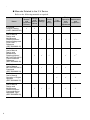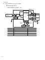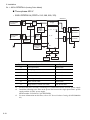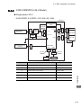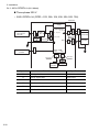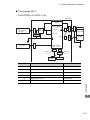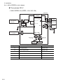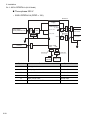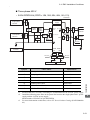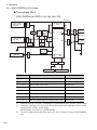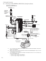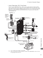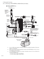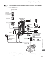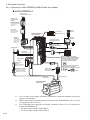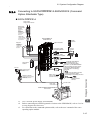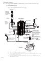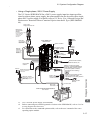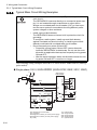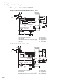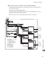
1
AC Servo Drives Σ -V Series USER'S MANUAL Setup Rotational Motor SGDV SERVOPACK SGMJV/SGMAV/SGMPS/SGMGV/SGMSV/SGMCS Servomotors 1 2 3 4 1 MANUAL NO. SIEP S800000 43C Overview of Setup 1 Installation 2 Wiring and Connection 3 Safety Function 4 Trial Operation (Checking Servomotor Operation) 5 Copyright © 2007 YASKAWA ELECTRIC CORPORATION All rights reserved. No part of this publication may be reproduced, stored in a retrieval system, or transmitted, in any form, or by any means, mechanical, electronic, photocopying, recording, or otherwise, without the prior written permission of Yaskawa. No patent liability is assumed with respect to the use of the information contained herein. Moreover, because Yaskawa is constantly striving to improve its high-quality products, the information contained in this manual is subject to change without notice. Every precaution has been taken in the preparation of this manual. Nevertheless, Yaskawa assumes no responsibility for errors or omissions. Neither is any liability assumed for damages resulting from the use of the information contained in this publication. About this Manual This manual describes procedures required for installation, wiring, and connecting Σ-V Series servo drives, including a JOG operation for servomotors not connected to machinery. Be sure to refer to this manual and perform setup operations correctly. Keep this manual in a location where it can be accessed for reference whenever required. Description of Technical Terms The following table shows the meanings of terms used in this manual. Term Meaning Servomotor Σ-V Series SGMJV, SGMAV, SGMPS, SGMGV, SGMSV, or SGMCS (Direct Drive) servomotor SERVOPACK Σ-V Series SGDV SERVOPACK Servo Drive A set including a servomotor and SERVOPACK (i.e., a servo amplifier) Servo System A servo control system that includes the combination of a servo drive with a host controller and peripheral devices Analog pulse model Analog voltage and pulse-train reference used for SERVOPACK interface. M-II model MECHATROLINK-II communications reference used for SERVOPACK interface. M-III model MECHATROLINK-III communications reference used for SERVOPACK interface. Command option attachable type SERVOPACK for which a command option module can be installed. IMPORTANT Explanations The following icon is displayed for explanations requiring special attention. • Indicates important information that should be memorized, as well as precautions, such as alarm displays, that do not involve potential damage to equipment. Notation Used in this Manual In this manual, the names of reverse signals (ones that are valid when low) are written with a forward slash (/) before the signal name, as shown in the following example: Example S-ON = /S-ON iii Manuals Related to the Σ-V Series Refer to the following manuals as required. Name Σ-V Series Product Catalog (KAEP S800000 42) Selecting Ratings Models System and and Specifi- Design Peripheral cations Devices 9 Trial Panels Operation Maintenance Trial and and and Operation Wiring Servo Inspection Adjustment 9 Σ-V Series User's Manual Design and Maintenance Rotational Motor/ Analog Voltage and Pulse Train Reference (SIEP S800000 45) 9 9 9 9 9* Σ-V Series User's Manual Design and Maintenance Rotational Motor/ MECHATROLINK-II Communications Reference (SIEP S800000 46) 9 9 9 9 9* Σ-V Series User’s Manual MECHATROLINK-II Command (SIEP S800000 54) 9 Σ-V Series User’s Manual Operation of Digital Operator (SIEP S800000 55) Σ-V Series User's Manual Design and Maintenance Rotational Motor/ Command Option Attachable Type (SIEP S800000 60) iv 9 9 9 9 9 9 9 9 9 9 Name Selecting Ratings Models System and and Specifi- Design Peripheral cations Devices Σ-V Series User’s Manual MECHATROLINK-III Command (SIEP S800000 63) (Will be available soon.) (cont’d) Trial Panels Operation Maintenance Trial and and and Operation Wiring Inspection Servo Adjustment 9 9 9 Σ-V Series User's Manual Design and Maintenance Rotational Motor/ MECHATROLINK-III Communications Reference (SIEP S800000 64) 9 9 9 9 9* Σ-V Series User's Manual Indexer Module (SIEP C720829 02) (Will be available soon.) 9 9 9 9 9* Σ-V Series User's Manual EtherCAT (CoE) Network Module (SIEP C720829 04) 9 9 9 9 9* AC SERVOMOTOR Safety Precautions (TOBP C230200 00) 9 9 Σ-V Series AC SERVOPACK SGDV Safety Precautions (TOBP C710800 10) 9 9 9 Σ-V Series Option Module Safety Precautions (TOBP C720829 00) 9 9 9 Σ-V Series Command Option Module Installation Guide (TOBP C720829 01) 9 9 9 v Name Selecting Ratings Models System and and Specifi- Design Peripheral cations Devices (cont’d) Trial Panels Operation Maintenance Trial and and and Operation Wiring Inspection Servo Adjustment Σ-V Series Indexer Module Installation Guide (TOBP C720829 02) 9 9 9 Σ-V Series Feedback Option Module Installation Guide (TOBP C720829 03) 9 9 9 Σ Series Digital Operator Safety Precautions (TOBP C730800 00) 9 ∗ Refer to these manuals for troubleshooting of problems which may occur during setup. (Troubleshooting which is common for command option modules is described in Σ-V Series User's Manual Design and Maintenance Rotational Motor/Command Option Attachable Type (SIEP S800000 60). vi Safety Information The following conventions are used to indicate precautions in this manual. Failure to heed precautions provided in this manual can result in serious or possibly even fatal injury or damage to the products or to related equipment and systems. WARNING CAUTION PROHIBITED Indicates precautions that, if not heeded, could possibly result in loss of life or serious injury. Indicates precautions that, if not heeded, could result in relatively serious or minor injury, damage to the product, or faulty operation. In some situations, the precautions indicated could have serious consequences if not heeded. Indicates prohibited actions that must not be performed. For example, this symbol would be used to indicate that fire is prohibited as follows: MANDATORY Indicates compulsory actions that must be performed. For example, this symbol would be used as follows to indicate that grounding is compulsory: vii Safety Precautions These safety precautions are very important. Read them before performing any procedures such as checking products on delivery, storage and transportation, installation, wiring, operation and inspection, or disposal. Be sure to always observe these precautions thoroughly. WARNING • Never touch any rotating motor parts while the motor is running. Failure to observe this warning may result in injury. • Before starting operation with a machine connected, make sure that an emergency stop can be applied at any time. Failure to observe this warning may result in injury or damage to the product. • Never touch the inside of the SERVOPACKs. Failure to observe this warning may result in electric shock. • Do not remove the cover of the power supply terminals while the power is ON. Failure to observe this warning may result in electric shock. • After the power is turned OFF or after a voltage resistance test, do not touch terminals while the CHARGE lamp is ON. Residual voltage may cause electric shock. • Follow the procedures and instructions provided in this manual for trial operation. Failure to do so may result not only in faulty operation and damage to equipment, but also in personal injury. • The multi-turn output range for the Σ-V Series absolute position detecting system is different from that of earlier systems (15-bit and 12-bit encoders). In particular, change the system to configure the Σ series infinite-length positioning system with the Σ-V Series. • The multi-turn limit value need not be changed except for special applications. Changing it inappropriately or unintentionally can be dangerous. • If the Multi-turn Limit Disagreement alarm occurs, check the setting of parameter Pn205 in the SERVOPACK to be sure that it is correct. If Fn013 is executed when an incorrect value is set in Pn205, an incorrect value will be set in the encoder. The alarm will disappear even if an incorrect value is set, but incorrect positions will be detected, resulting in a dangerous situation where the machine will move to unexpected positions. • Do not remove the front cover, cables, connectors, or optional items from the upper front of the SERVOPACK while the power is ON. Failure to observe this warning may result in electric shock. • Do not damage, press, exert excessive force on, or place heavy objects on the cables. Failure to observe this warning may result in electric shock, stopping operation of the product, or fire. • Do not modify the product. Failure to observe this warning may result in injury, fire, or damage to the product. viii WARNING • Provide an appropriate braking device on the machine side to ensure safety. The holding brake on a servomotor with a brake is not a braking device for ensuring safety. Failure to observe this warning may result in injury. • Do not come close to the machine immediately after resetting a momentary power loss. The machine may restart unexpectedly. Take appropriate measures to ensure safety against an unexpected restart. Failure to observe this warning may result in injury. • Connect the ground terminal according to local electrical codes (100 Ω or less for a SERVOPACK with a 100, 200 V power supply. 10 Ω or less for a SERVOPACK with a 400 V power supply.) Improper grounding may result in electric shock or fire. • Installation, disassembly, or repair must be performed only by authorized personnel. Failure to observe this warning may result in electric shock or injury. • The person who designs a system using the safety function (Hard Wire Baseblock function) must have full knowledge of the related safety standards and full understanding of the instructions in Σ-V Series User’s Manual Design and Maintenance (SIEP S800000 45/46/60/64). Failure to observe this warning may result in injury or damage to the product. Storage and Transportation CAUTION • Do not store or install the product in the following locations. Failure to observe this caution may result in fire, electric shock, or damage to the product. • Locations subject to direct sunlight • Locations subject to temperatures outside the range specified in the storage/ installation temperature conditions • Locations subject to humidity outside the range specified in the storage/installation humidity conditions • Locations subject to condensation as the result of extreme changes in temperature • Locations subject to corrosive or flammable gases • Locations subject to dust, salts, or iron dust • Locations subject to exposure to water, oil, or chemicals • Locations subject to shock or vibration • Do not hold the product by the cables, motor shaft or detector while transporting it. Failure to observe this caution may result in injury or malfunction. • Do not place any load exceeding the limit specified on the packing box. Failure to observe this caution may result in injury or malfunction. ix Storage and Transportation (cont’d) CAUTION • If disinfectants or insecticides must be used to treat packing materials such as wooden frames, pallets, or plywood, the packing materials must be treated before the product is packaged, and methods other than fumigation must be used. Example: Heat treatment, where materials are kiln-dried to a core temperature of 56°C for 30 minutes or more. If the electronic products, which include stand-alone products and products installed in machines, are packed with fumigated wooden materials, the electrical components may be greatly damaged by the gases or fumes resulting from the fumigation process. In particular, disinfectants containing halogen, which includes chlorine, fluorine, bromine, or iodine can contribute to the erosion of the capacitors. Installation CAUTION • Never use the product in an environment subject to water, corrosive gases, inflammable gases, or combustibles. Failure to observe this caution may result in electric shock or fire. • Do not step on or place a heavy object on the product. Failure to observe this caution may result in injury. • Do not cover the inlet or outlet ports and prevent any foreign objects from entering the product. Failure to observe this caution may cause internal elements to deteriorate resulting in malfunction or fire. • Be sure to install the product in the correct direction. Failure to observe this caution may result in malfunction. • Provide the specified clearances between the SERVOPACK and the control panel or with other devices. Failure to observe this caution may result in fire or malfunction. • Do not apply any strong impact. Failure to observe this caution may result in malfunction. x Wiring CAUTION • Be sure to wire correctly and securely. Failure to observe this caution may result in motor overrun, injury, or malfunction. • Do not connect a commercial power supply to the U, V, or W terminals for the servomotor connection. Failure to observe this caution may result in injury or fire. • Securely connect the main circuit power supply terminals and servomotor connection terminals. Failure to observe this caution may result in fire. • Do not bundle or run the main circuit cables together with the I/O signal cables or the encoder cables in the same duct. Keep them separated by at least 30 cm. Failure to do so may result in malfunction. • Use shielded twisted-pair wires or multi-core shielded twisted-pair wires for I/O signal cables and the encoder cables. • I/O signal cables must be no longer than 3 m, encoder cables must be no longer than 50 m, and control power supply (+24 V, 0 V) cables for a 400 V input SERVOPACK must be no longer than 10 m. • Do not touch the power terminals while the CHARGE lamp is ON after turning power OFF because high voltage may still remain in the SERVOPACK. Make sure the charge indicator is off first before starting an inspection. • Observe the following precautions when wiring main circuit terminals. • Remove detachable main circuit terminals from the SERVOPACK prior to wiring. • Insert only one main circuit cable per opening in the main circuit terminals. • Make sure that no part of the core wire comes into contact with (i.e., short-circuit) adjacent wires. • Install a battery at either the host controller or the battery unit of the encoder, but not both. It is dangerous to install batteries at both ends simultaneously, because that sets up a loop circuit between the batteries. • Always use the specified power supply voltage. An incorrect voltage may result in fire or malfunction. • Take appropriate measures to ensure that the input power supply is supplied within the specified voltage fluctuation range. Be particularly careful in places where the power supply is unstable. An incorrect power supply may result in damage to the product. • Install external breakers or other safety devices against short-circuiting in external wiring. Failure to observe this caution may result in fire. • Take appropriate and sufficient countermeasures for each form of potential interference when installing systems in the following locations. • Locations subject to static electricity or other forms of noise • Locations subject to strong electromagnetic fields and magnetic fields • Locations subject to possible exposure to radioactivity • Locations close to power supplies Failure to observe this caution may result in damage to the product. xi Wiring (cont’d) CAUTION • Do not reverse the polarity of the battery when connecting it. Failure to observe this caution may result in damage to the battery, the SERVOPACK, or cause an explosion. • Wiring or inspection must be performed by a technical expert. • Use a 24 VDC power supply with double insulation or reinforced insulation. • Failures caused by incorrect wiring or wrong voltage application in the brake circuit may damage the equipment or cause an accident resulting in death or injury. Follow the procedures and instructions for wiring and trial operation precisely as described in this manual. • Leakage current may increase depending on the type of noise filter and the grounding conditions. When using a detector or a breaker for leakage current, select the appropriate one by considering the type of noise filter and the grounding conditions. For details, contact the manufacturer of the noise filter. • Incorrect wiring or incorrect voltage application to the output circuit may cause short-circuit. The above failures will prevent the holding brake from working, which may damage the machine or cause an accident resulting in death or injury. • Inverting the polarity of the brake signal (/BK), i.e. positive logic, will prevent the holding brake from working in case of its signal line disconnection. If this setting is absolutely necessary, check the operation and confirm that there are no safety problems. Operation CAUTION • Conduct trial operations on the servomotor alone, with the motor shaft disconnected from the machine to avoid accidents. Failure to observe this caution may result in injury. • During trial operation, confirm that the holding brake works correctly. Furthermore, secure system safety against problems such as signal line disconnection. • Before starting operation with a machine connected, change the settings to match the parameters of the machine. Starting operation without matching the proper settings may cause the machine to run out of control or malfunction. • Do not frequently turn power ON and OFF. • Frequently turning power ON and OFF causes elements inside the SERVOPACK to deteriorate. Do not use the servo drive with an application that requires frequently turning power ON and OFF. • After the actual operation starts, the allowable interval for turning power ON and OFF is one hour or longer. xii Operation (cont’d) CAUTION • When using JOG operations (Fn002) origin search operations (Fn003), or EasyFFT operations (Fn206), the dynamic brake function does not work for reverse overtravel or forward overtravel. Take necessary precautions. Failure to observe this caution may result in damage to the product. • When using the servomotor for a vertical axis, install safety devices to prevent workpieces from falling due to alarms or overtravels. Set the servomotor so that it will stop in the zero clamp state when overtravel occurs. Failure to observe this caution may cause workpieces to fall due to overtravel. • When not using turning-less function, set to the correct moment of inertia ratio (Pn103). Setting to an incorrect moment of inertia ratio may cause vibration. • Do not touch the SERVOPACK heatsinks, regenerative resistor, or servomotor while power is ON or soon after the power is turned OFF. Failure to observe this caution may result in burns due to high temperatures. • Do not make any extreme adjustments or setting changes of parameters. Failure to observe this caution may result in injury or damage to the product due to unstable operation. • When an alarm occurs, remove the cause, reset the alarm after confirming safety, and then resume operation. Failure to observe this caution may result in damage to the product, fire, or injury. • Do not use the holding brake of the servomotor for braking. Failure to observe this caution may result in malfunction. • Always use the servomotor and SERVOPACK in one of the specified combinations. Failure to observe this caution may result in fire or malfunction. • The servomotor stopping method of turning the main-circuit or control-circuit power OFF without turning the servo OFF during operation can not be set in Parameter Pn001. Use the following method to stop the servomotor. • When turning the main-circuit power OFF without turning the servo OFF: The servomotor will be stopped by dynamic braking (DB). • When turning the control-circuit power OFF without turning the servo OFF: The stopping method will vary depending on the SERVOPACK model. Refer to the Σ-V Series User's Manual Design and Maintenance for details. xiii Maintenance and Inspection CAUTION • Do not disassemble the SERVOPACK. Failure to observe this caution may result in electric shock or injury. • Do not attempt to change wiring while the power is ON. Failure to observe this caution may result in electric shock or injury. • When replacing the SERVOPACK, resume operation only after copying the previous SERVOPACK parameters to the new SERVOPACK. Failure to observe this caution may result in damage to the product. • Be sure to eliminate static electricity before operating buttons and switches inside the front cover. Failure to observe this caution may result in damage to the product. Disposal CAUTION • When disposing of the products, treat them as ordinary industrial waste. General Precautions Observe the following general precautions to ensure safe application. • The products shown in illustrations in this manual are sometimes shown without covers or protective guards. Always replace the cover or protective guard as specified first, and then operate the products in accordance with the manual. • The drawings presented in this manual are typical examples and may not match the product you received. • This manual is subject to change due to product improvement, specification modification, and manual improvement. When this manual is revised, the manual code is updated and the new manual is published as a next edition. The edition number appears on the front and back covers. • If the manual must be ordered due to loss or damage, inform your nearest Yaskawa representative or one of the offices listed on the back of this manual. • Yaskawa will not take responsibility for the results of unauthorized modifications of this product. Yaskawa shall not be liable for any damages or troubles resulting from unauthorized modification. xiv Warranty (1) Details of Warranty Period of Warranty The period of warranty for a product that was purchased (hereafter “delivered product”) is one year from the time of delivery to the location specified by the customer or 18 months from the time of shipment from the Yaskawa factory, whichever is sooner. Scope of Warranty Yaskawa shall replace or repair a defective product free of change if a defect attributable to Yaskawa occurs during the period of warranty above. Defects due to the delivered product reaching the end of its service life and replacement of parts that require replacement or that have a limited service life are also outside the scope of this warranty. Failures that occur for any of the following causes are outside the scope of the warranty. 1. Using or handling the product under conditions or in environments not described in product catalogs or manuals, or separately agreed-upon specifications 2. Causes not attributable to the delivered product itself 3. Modifications or repairs not performed by Yaskawa 4. Using the delivered product in a manner in which it was not originally intended 5. Causes that were not foreseeable with the scientific and technological understanding at the time of shipment from Yaskawa 6. Events for which Yaskawa is not responsible, such as natural or human-made disasters (2) Limitations of Liability 1. Yaskawa shall in no event be responsible for any damage or loss of opportunity to the customer that arises due to failure of the delivered product. 2. Yaskawa shall not be responsible for programming (including parameter settings) or the results of program execution if a programmable Yaskawa product was programmed by the user or by a third party. xv (3) Suitability for Use 1. It is the customer’s responsibility to confirm conformity with any standards, codes, or regulations that apply if the Yaskawa product is used in combination with any other products. 2. The customer must confirm that the Yaskawa product is suitable for the systems, machines, and equipment used by the customer. 3. Consult with Yaskawa to determine whether use in the following applications is acceptable. If use in the application is acceptable, use the product with extra allowance in ratings and specifications, and provide safety measures to minimize hazards in the event of failure. • Outdoor use, use involving potential chemical contamination or electrical interference, or use in conditions or environments not described in product catalogs or manuals • Nuclear energy control systems, combustion systems, railroad systems, aviation systems, vehicle systems, medical equipment, amusement machines, and installations subject to separate industry or government regulations • Systems, machines, and equipment that may present a risk to life or property • Systems that require a high degree of reliability, such as systems that supply gas, water, or electricity, or systems that operate continuously 24 hours a day • Other systems that require a similar high degree of safety 4. Never use the product for an application involving serious risk to life or property without first ensuring that the required safety has been designed into the system with risk warnings and redundancy, and that the Yaskawa product is properly rated and installed. 5. The circuit examples and other application examples described in product catalogs and manuals are for reference. Check the functionality and safety of the actual devices and equipment to be used before using the product. 6. Read and understand all use prohibitions and precautions, and operate the Yaskawa product correctly to prevent accidental harm to third parties. (4) Changes to Specifications The names, specifications, appearance, and accessories of products in product catalogs and manuals may be changed at any time based on improvements and other reasons. When a catalog or a manual is revised, the catalog or manual code is updated and the new catalog or manual is published as a next edition. Consult with your Yaskawa representative to confirm the actual specifications before purchasing a product. xvi Applicable Standards North American Safety Standards (UL) UL∗ Standards (UL File No.) Model SERVOPACK • SGDV UL508C (E147823) Servomotor • • • • • UL1004 (E165827) SGMJV SGMAV SGMPS SGMGV SGMSV ∗ Underwriters Laboratories Inc. European Standards Model SERVOPACK • SGDV Servomotor • • • • • SGMJV SGMAV SGMPS SGMGV SGMSV Low Voltage Directive EMC Directive EMI EMS Safety Standards EN55011/A2 EN50178 EN61800-5-1 group 1 class A EN61800-3 EN61800-3 EN61000-6-2 EN954-1 IEC61508-1 to 4 IEC60034-1 IEC60034-5 IEC60034-8 IEC60034-9 EN61800-3 EN61000-6-2 – EN55011/A2 group 1 class A EN61800-3 Note: Because SERVOPACKs and servomotors are built into machines, certification is required after installation in the user’s product. xvii CONTENTS About this Manual . . . . . . . . . . . . . . . . . . . . . . . . . . . . . . . . . . . . . . . . . . . . . . . . . iii Safety Precautions . . . . . . . . . . . . . . . . . . . . . . . . . . . . . . . . . . . . . . . . . . . . . . . viii Warranty . . . . . . . . . . . . . . . . . . . . . . . . . . . . . . . . . . . . . . . . . . . . . . . . . . . . . . . xv Applicable Standards . . . . . . . . . . . . . . . . . . . . . . . . . . . . . . . . . . . . . . . . . . . . . xvii 1 Overview of Setup . . . . . . . . . . . . . . . . . . . . . . . . . . . . . . . . . . . . . . . . 1-1 2 Installation . . . . . . . . . . . . . . . . . . . . . . . . . . . . . . . . . . . . . . . . . . . . . . 2-1 2.1 Installation Environment and Applicable Standards . . . . . . . . . . . . . . . . . . . . . . . . . . . 2-2 2.1.1 Servomotor Installation Environment . . . . . . . . . . . . . . . . . . . . . . . . . . . . . . . . . 2-2 2.1.2 SERVOPACK Installation Environment . . . . . . . . . . . . . . . . . . . . . . . . . . . . . . . . 2-3 2.1.3 Installation Conditions for Applicable Standards . . . . . . . . . . . . . . . . . . . . . . . . . 2-4 2.2 Servomotor Installation . . . . . . . . . . . . . . . . . . . . . . . . . . . . . . . . . . . . . . . . . . . . . . . . . 2-5 2.2.1 Orientation . . . . . . . . . . . . . . . . . . . . . . . . . . . . . . . . . . . . . . . . . . . . . . . . . . . . . 2-5 2.2.2 Installation Standards . . . . . . . . . . . . . . . . . . . . . . . . . . . . . . . . . . . . . . . . . . . . . 2-5 2.2.3 Connecting Servomotor to Machine . . . . . . . . . . . . . . . . . . . . . . . . . . . . . . . . . . 2-6 2.2.4 Protective Structure . . . . . . . . . . . . . . . . . . . . . . . . . . . . . . . . . . . . . . . . . . . . . . . 2-7 2.2.5 Other Precautions . . . . . . . . . . . . . . . . . . . . . . . . . . . . . . . . . . . . . . . . . . . . . . . . 2-8 2.3 SERVOPACK Installation . . . . . . . . . . . . . . . . . . . . . . . . . . . . . . . . . . . . . . . . . . . . . . . 2-9 2.3.1 Orientation . . . . . . . . . . . . . . . . . . . . . . . . . . . . . . . . . . . . . . . . . . . . . . . . . . . . . 2-9 2.3.2 Installation Standards . . . . . . . . . . . . . . . . . . . . . . . . . . . . . . . . . . . . . . . . . . . . 2-10 2.4 EMC Installation Conditions . . . . . . . . . . . . . . . . . . . . . . . . . . . . . . . . . . . . . . . . . . . . 2-12 2.4.1 SGDV-01A (Analog Pulse Model) . . . . . . . . . . . . . . . . . . . . . . . . . . . . 2-12 2.4.2 SGDV-11A (M-II Model) . . . . . . . . . . . . . . . . . . . . . . . . . . . . . . . . . . . . 2-19 2.4.3 SGDV-21A (M-III Model) . . . . . . . . . . . . . . . . . . . . . . . . . . . . . . . . . . . 2-26 2.4.4 SGDV-E1A (Command Option Attachable Type) . . . . . . . . . . . . . . . . . 2-33 2.4.5 Other Precautions . . . . . . . . . . . . . . . . . . . . . . . . . . . . . . . . . . . . . . . . . . . . . . . 2-33 3 Wiring and Connection . . . . . . . . . . . . . . . . . . . . . . . . . . . . . . . . . . . . . 3-1 3.1 Precautions for Wiring . . . . . . . . . . . . . . . . . . . . . . . . . . . . . . . . . . . . . . . . . . . . . . . . . 3-2 3.2 System Configuration Diagram . . . . . . . . . . . . . . . . . . . . . . . . . . . . . . . . . . . . . . . . . . 3-3 3.2.1 Connecting to SGDV-01A SERVOPACK (Analog Pulse Model) . . . . . . 3-3 3.2.2 Connecting to SGDV-11A SERVOPACK (M-II Model) . . . . . . . . . . . . . . 3-7 3.2.3 Connecting to SGDV-21A SERVOPACK (M-III Model) . . . . . . . . . . . . 3-11 3.2.4 Connecting to SGDV-E1A SERVOPACK (Command Option Attachable Type) . . . . . . . . . . . . . . . . . . . . . . . . . . . . . . . . 3-15 3.3 Main Circuit Wiring . . . . . . . . . . . . . . . . . . . . . . . . . . . . . . . . . . . . . . . . . . . . . . . . . . . 3-19 3.3.1 Names and Functions of Main Circuit Terminals . . . . . . . . . . . . . . . . . . . . . . . . 3-19 3.3.2 SERVOPACK Main Circuit Wire Size . . . . . . . . . . . . . . . . . . . . . . . . . . . . . . . . 3-20 3.3.3 Typical Main Circuit Wiring Examples . . . . . . . . . . . . . . . . . . . . . . . . . . . . . . . . 3-24 3.3.4 Wiring the Main Circuit Terminal Connector (Spring Type) . . . . . . . . . . . . . . . . 3-28 3.4 Connecting Regenerative Resistors . . . . . . . . . . . . . . . . . . . . . . . . . . . . . . . . . . . . . . 3-31 3.4.1 Connecting Regenerative Resistor . . . . . . . . . . . . . . . . . . . . . . . . . . . . . . . . . . 3-31 xviii 4 Safety Function . . . . . . . . . . . . . . . . . . . . . . . . . . . . . . . . . . . . . . . . . . 4-1 4.1 4.2 4.3 4.4 4.5 Outline . . . . . . . . . . . . . . . . . . . . . . . . . . . . . . . . . . . . . . . . . . . . . . . . . . . . . . . . . . . . . Hard Wire Base Block (HWBB) Function . . . . . . . . . . . . . . . . . . . . . . . . . . . . . . . . . . . Safety Function Signal (CN8) Names and Functions . . . . . . . . . . . . . . . . . . . . . . . . . Precautions When Not Using the Safety Function . . . . . . . . . . . . . . . . . . . . . . . . . . . . When Using the Safety Function . . . . . . . . . . . . . . . . . . . . . . . . . . . . . . . . . . . . . . . . . 4-2 4-3 4-4 4-4 4-5 5 Trial Operation (Checking Servomotor Operation) . . . . . . . . . . . . . . . 5-1 5.1 5.2 5.3 5.4 5.5 Outline . . . . . . . . . . . . . . . . . . . . . . . . . . . . . . . . . . . . . . . . . . . . . . . . . . . . . . . . . . . . . 5-2 Inspection and Checking before Trial Operation . . . . . . . . . . . . . . . . . . . . . . . . . . . . . 5-2 JOG Operation Using a Panel Operator . . . . . . . . . . . . . . . . . . . . . . . . . . . . . . . . . . . 5-5 JOG Operation Using a Digital Operator . . . . . . . . . . . . . . . . . . . . . . . . . . . . . . . . . . . 5-7 JOG Operation Using SigmaWin+ . . . . . . . . . . . . . . . . . . . . . . . . . . . . . . . . . . . . . . . 5-10 Revision History xix 1 Overview of Setup Overview of Setup This chapter describes how to set up the Σ-V series of servo drives. 1 1-1 1 Overview of Setup This chapter describes the flow of the setup procedure from installation until a JOG operation. A panel operator, a digital operator, and SigmaWin+, (which is an engineering tool that can be used with a PC) are available to set up a servo drive. The panel operator is included with the SERVOPACK of analog pulse models, and the digital operator and SigmaWin+ are sold separately. CAUTION • An alarm or warning may be generated if communications are executed with the host controller during operation using SigmaWin+ or the digital operator. If an alarm or warning is generated, the process currently being executed may be aborted and the system may stop. Be sure to read 5.2 Inspection and Checking before Trial Operation. Operation Install the servomotor and SERVOPACK. Reference (in this manual) Chapter 2 Installation ↓ Perform the required wiring and connections for a JOG operation. Chapter 3 Wiring and Connection ↓ Perform a JOG operation for the servomotor using • the panel operator • the digital operator, or • SigmaWin+ Chapter 5 Trial Operation (Checking Servomotor Operation) zTrial Operation Using the Panel Operator * →5.3 JOG Operation Using a Panel Operator zTrial Operation Using the Digital Operator →5.4 JOG Operation Using a Digital Operator zTrial Operation Using SigmaWin+. →5.5 JOG Operation Using SigmaWin+ ∗ Trial operation using the panel operator is available with analog pulse models only. 1-2 2 Installation This chapter describes how to install the servomotor and the SERVOPACK. 2.1 Installation Environment and Applicable Standards . . . . . . . . . 2-2 2.1.1 Servomotor Installation Environment . . . . . . . . . . . . . . . . . . . . . . 2-2 2.1.2 SERVOPACK Installation Environment . . . . . . . . . . . . . . . . . . . . 2-3 2.1.3 Installation Conditions for Applicable Standards . . . . . . . . . . . . . . 2-4 2.2 Servomotor Installation . . . . . . . . . . . . . . . . . . . . . . . . . . . . . . . 2-5 2.2.1 2.2.2 2.2.3 2.2.4 2.2.5 Orientation . . . . . . . . . . . . . . . . . . . . . . . . . . . . . . . . . . . . . . . . . . 2-5 Installation Standards . . . . . . . . . . . . . . . . . . . . . . . . . . . . . . . . . . 2-5 Connecting Servomotor to Machine . . . . . . . . . . . . . . . . . . . . . . . 2-6 Protective Structure . . . . . . . . . . . . . . . . . . . . . . . . . . . . . . . . . . . 2-7 Other Precautions . . . . . . . . . . . . . . . . . . . . . . . . . . . . . . . . . . . . . 2-8 2.3 SERVOPACK Installation . . . . . . . . . . . . . . . . . . . . . . . . . . . . . 2-9 2.3.1 Orientation . . . . . . . . . . . . . . . . . . . . . . . . . . . . . . . . . . . . . . . . . . 2-9 2.3.2 Installation Standards . . . . . . . . . . . . . . . . . . . . . . . . . . . . . . . . . 2-10 2.4.1 2.4.2 2.4.3 2.4.4 2.4.5 SGDV-01A (Analog Pulse Model) . . . . . . . . . . . . . . . . . 2-12 SGDV-11A (M-II Model) . . . . . . . . . . . . . . . . . . . . . . . . . 2-19 SGDV-21A (M-III Model) . . . . . . . . . . . . . . . . . . . . . . . . 2-26 SGDV-E1A (Command Option Attachable Type) . . . . . . 2-33 Other Precautions . . . . . . . . . . . . . . . . . . . . . . . . . . . . . . . . . . . . 2-33 Installation 2.4 EMC Installation Conditions . . . . . . . . . . . . . . . . . . . . . . . . . . 2-12 2 2-1 2 Installation 2.1.1 Servomotor Installation Environment 2.1 Installation Environment and Applicable Standards The installation environment and the applicable standards for servomotors and SERVOPACKs are described in this section. 2.1.1 Servomotor Installation Environment Ambient temperature: 0 to 40°C Ambient humidity: 80% RH or less (with no condensation) Altitude: 1, 000 m or less Vibration resistance The servomotor will withstand the following vibration acceleration in three directions: vertical, side to side, and front to back. Front to Back Vertical Side to Side Horizontal Impact Applied to the Servomotor Servomotor Model Vibration Acceleration at Flange SGMJV, SGMAV, SGMPS, SGMCS-02 to -35 49 m/s2 SGMGV-03 to -44, SGMSV-10 to -50 49 m/s2 (Front to back direction: 24.5m/s2) SGMGV-55 to -1E, SGMCS-45 to -2Z 24.5 m/s2 SGMSV-70 14.7 m/s2 Shock resistance: 490 m/s2 at servomotor flange Installation site: An environment that satisfies the following conditions • Indoors and free of corrosive or explosive gases • Well-ventilated and free of dust and moisture • Facilitates inspection and cleaning • Free of high magnetic field 2-2 2.1 Installation Environment and Applicable Standards SERVOPACK Installation Environment Surrounding air temperature: 0 to 55°C Ambient humidity: 90% RH or less (with no condensation) Altitude: 1,000 m or less Vibration resistance: 4.9 m/s2 Shock resistance: 19.6 m/s2 Installation Precautions • Mounting in a Control Panel To prevent the temperature around the SERVOPACK from exceeding 55°C, take into account the size of the control panel, the layout of the SERVOPACK, and the cooling method. For details, refer to 2.3 SERVOPACK Installation. • Mounting Near a Heating Unit To prevent the temperature around the SERVOPACK from exceeding 55°C, suppress radiant heat from the heating unit and temperature rise due to convection. • Mounting Near a Vibration Source To prevent vibration from being transmitted to the SERVOPACK, install a vibration isolator underneath the SERVOPACK. • Mounting to a Location Exposed to Corrosive Gas Take measures to prevent exposure to corrosive gas. Corrosive gases will not immediately affect the SERVOPACK, but will eventually cause electronic components and contactor-related devices to malfunction. • Other Locations Do not mount the SERVOPACK in locations subject to high temperatures, high humidity, dripping water, cutting oil, dust, iron filings, or radiation. <Note> Installation 2.1.2 2 When storing the SERVOPACK with the power OFF, store it in an environment with the following temperature and humidity: • -20 to +85°C, 90% RH or less. (with no condensation) 2-3 2 Installation 2.1.3 Installation Conditions for Applicable Standards 2.1.3 2-4 Installation Conditions for Applicable Standards Applicable Standards UL508C EN50178, EN55011/A2 group1 classA, EN61000-6-2, EN61800-3, EN61800-5-1, EN954-1, IEC61508-1 to 4 Operating Conditions Overvoltage Category: III Pollution degree: 2 Protection class: IP10 Installation Conditions UL Standard and Low Voltage Directive: Satisfy the conditions outlined in Σ-V Series AC SERVOPACK SGDV Safety Precautions (TOBP C710800 10) EMC Directive: Certification is required after installation in the user’s machine under the conditions outlined in 2.4 EMC Installation Conditions of this manual. 2.2 Servomotor Installation 2.2 Servomotor Installation 2.2.1 Orientation Servomotors can be installed either horizontally or vertically. Servomotors with gears can be installed only horizontally, depending on gear lubrication conditions. Refer to Σ-V Series Product Catalog (KAEP S800000 42) for details. Installation Standards The motor rated specifications (rated output, rated torque, and rated speed) are the continuous allowable values at an ambient temperature of 40°C when servomotors are installed with heat sinks. For more information on heat sinks, refer to Σ-V Series Product Catalog (KAEP S800000 42). When a motor is mounted on a small surface, the motor temperature may rise considerably because of the limited heat radiating abilities of the surface. To restrict the temperature rise, you should either mount a heat sink or limit the electrical, thermal, and mechanical stress on the motor (derating). Refer to Σ-V Series Product Catalog (KAEP S800000 42) for the relation between heat sink size and derating. The data in the catalog is given only for reference, as the actual temperature rise depends on how the heat sink (motor mounting section) is fixed on the installation surface and what material is used for the motor mounting section. Always check the actual motor temperature. If the servomotor is covered, or if a heating element is installed near the servomotor, the motor temperature may rise considerably. In this case, take following countermeasures. • Reduce the load ratio. • Reconsider the motor heating conditions. • Install a cooling fan to forcedly cool the motor. Installation 2.2.2 2 2-5 2 Installation 2.2.3 Connecting Servomotor to Machine 2.2.3 Connecting Servomotor to Machine The end of the motor shaft is coated with anticorrosive paint. Thoroughly remove the paint prior to installation. Align the shaft of the servomotor with the shaft of the machine, and then couple the shafts. Install the servomotor so that alignment accuracy falls within the following range. Vibration will damage the bearings or encoders if the shafts are not properly aligned. Do not allow direct impact to be applied to the shafts when installing the coupling as the encoder mounted on the opposite end of the shaft may be damaged. Alignment Accuracy Measure this distance at four different positions on the circumference. The difference between the maximum and minimum measurements must be 0.03 mm or less. (Turn together with coupling.) 2-6 2.2 Servomotor Installation Protective Structure The servomotor protective structure* is described below. Model Without Gears With Gears IP65 IP55 SGMPS IP55 IP67 (Optional) IP55 SGMGV IP67 − SGMSV IP67 (SGMSV-70 servomotor only: IP22) − SGMCS-02 to -35 IP42 (expect for gaps on the rotating section of the shaft) − SGMCS-45 to -2Z IP44 − SGMJV, SGMAV ∗ Except through shaft section. The protective structure specifications can be satisfied only when using a specified cable. When the through shaft section is subject to oil exposure, refer to 2.2.5 Other Precautions. Flange Through shaft section This refers to the gap where the shaft protrudes from the end of the motor. Shaft Installation 2.2.4 2 2-7 2 Installation 2.2.5 Other Precautions 2.2.5 Other Precautions Handling Oil and Water If the servomotor is used in a location that is subject to water or oil mist, use a servomotor with an oil seal to seal the through shaft section. Precautions on using a servomotor with an oil seal are described below. • Put the oil surface under the oil seal lip. • Use an oil seal in favorably lubricated condition. • When using a servomotor with its shaft upward direction, be sure that oil will not stay in the oil seal lips. Cable Stress Make sure there are no bends or tension on the motor main circuit cables and encoder cables. Be especially careful to wire encoder cables so that they are not subject to stress because the core wires are very thin at only 0.2 or 0.3 mm2. Connectors Observe the following precautions: • Make sure there is no foreign matters such as dust and metal chips in the connector before connecting. • When the connectors are connected to the motor, be sure to connect the end of motor main circuit cables before connecting the encoder cable’s end. If the encoder cable’s end is connected, the encoder may break because of the voltage differences between FG. • Make sure of the pin arrangement. • Do not apply shock to resin connectors. Otherwise, they may be damaged. • When handling a servomotor with its cables connected, hold the servomotor or the connectors and cables will be damaged. • Fix the connector to SGMJV, SGMAV, SGMPS-01/-02/-04 or SGMGV-03/-05 servomotors with screws. Make sure that the connector is securely fixed with screws. If not, the protective construction specifications may not be satisfied. • Be sure not to apply stress on the connector. The connector may be damaged by stress. Radial and Thrust loads Design the mechanical system so thrust and radial loads applied to the servomotor shaft end during operation fall within the allowable ranges of each motor. Refer to Σ-V Series Product Catalog (KAEP S800000 42) for the allowable ranges. 2-8 2.3 SERVOPACK Installation 2.3 SERVOPACK Installation 2.3.1 Orientation The SERVOPACK is available in models that are base-mounted, models that are rack-mounted, and models that are duct-ventilated. In any case, mount the SERVOPACK with a vertical orientation. Firmly secure the SERVOPACK to the mounting surface, using either two or four mounting holes depending on the SERVOPACK capacity. Note: For SERVOPACKs of command option attachable type, installation conditions may differ depending on the attached option module. For details, refer to the user’s manual for each option module. • Base-mounted Base Air Flow • Rack-mounted Installation Rack 2 Air Flow 2-9 2 Installation 2.3.2 Installation Standards • Duct-ventilated Duct Air Flow 2.3.2 Installation Standards Observe the standards for mounting SERVOPACKs in control panels, including those for the mounting SERVOPACKs side by side in one control panel as shown in the following illustration. Note: For SERVOPACKs of command option attachable type, installation conditions may differ depending on the attached option module. For details, refer to the user’s manual for each option module. • SERVOPACK Mounting Orientation Mount the SERVOPACK vertically to the wall, with the front panel (the side with the panel operator display) facing out. • Cooling Refer to the following diagram and leave sufficient space for cooling by fans and natural convection. 2-10 2.3 SERVOPACK Installation • Mounting SERVOPACKs Side by Side in a Control Panel Fan 30 mm or more Fan 40 mm or more Width varies with SERVOPACK model 40 mm or more Leave sufficient space on each side and at the top and the bottom of each SERVOPACK. The width on each side varies in accordance with the models of the SERVOPACKS used. SERVOPACK Model SGDV- Side Left Right R70F, R90F, 2R1F, R70A, R90A, 1R6A, 2R8A 1 mm or more 2R8F, 3R8A, 5R5A, 7R6A 1 mm or more 10 mm or more 120A, 180A, 200A, 330A, 470A, 550A, 590A, 780A, 1R9D, 3R5D, 5R4D, 8R4D, 120D, 170D, 210D, 260D, 280D, 370D Top and bottom 40 mm or more 10 mm or more • Inside the Control Panel The conditions inside the control panel should be the same as the environmental conditions of the SERVOPACK. Refer to 2.1.2 SERVOPACK Installation Environment. Installation Also install cooling fans above the SERVOPACKs to disperse local pockets of warmer air around the SERVOPACKs. 2 2-11 2 Installation 2.4.1 SGDV-01A (Analog Pulse Model) 2.4 EMC Installation Conditions This section describes the recommended installation conditions that satisfy EMC guidelines for each model of the SGDV SERVOPACK. The conditions required for the standard type (base-mounted) of SERVOPACK are described. Refer to this section for other SERVOPACK models such as the rack-mounted types as well. This section describes the EMC installation conditions satisfied in test conditions prepared by Yaskawa. The actual EMC level may differ depending on the actual system’s configuration, wiring, and other conditions. However, because this product is built-in, check that the following conditions are still met after being installed in the user’s product. The applicable standards are EN55011/A2 group 1 class A, EN61800-3, and EN61000-6-2. 2.4.1 SGDV-01A (Analog Pulse Model) Single-phase 100 V • SGDV-F01A ( = R70, R90, 2R1, 2R8) Shield box L1C, L2C 3 CN1 CN8 Core Core Clamp 1 Host controller Symbol 2-12 Cable Name Clamp CN2 Two turn Brake Servomotor One turn Core Two turn PE Clamp L1, L2 Core Core Surge absorber Noise filter SERVOPACK U, V, W Core 5 Clamp One turn Power supply: Single-phase 100 VAC Clamp Brake Power Supply 4 Encoder Two turn PE 2 Safety unit Specification c I/O signal cable d Safety signal cable Shield cable e Motor main circuit cable Shield cable f Encoder cable Shield cable g Main circuit cable Shield cable Shield cable 2.4 EMC Installation Conditions Three-phase 200 V • SGDV-A01A ( = R70, R90, 1R6, 2R8, 3R8, 5R5, 7R6) Shield box Host controller Cable Name 4 Encoder CN8 Core Clamp 1 Servomotor Two turn PE 2 Safety unit Specification c I/O signal cable Shield cable d Safety signal cable Shield cable e Motor main circuit cable Shield cable f Encoder cable Shield cable g Main circuit cable Shield cable Installation Core Clamp CN2 Two turn Brake One turn L1C, L2C CN1 Symbol Clamp 3 One turn PE Clamp L1, L2, L3 Core Surge absorber SERVOPACK U, V, W Core Core 5 Noise filter Core Power supply: Three-phase 200 VAC Clamp Brake Power Supply 2 2-13 2 Installation 2.4.1 SGDV-01A (Analog Pulse Model) Three-phase 200 V • SGDV-A01A ( = 120) Shield box CN2 Core Two turn Host controller 2-14 Cable Name Servomotor 4 Encoder CN8 Core Clamp 1 Brake One turn L1C, L2C CN1 Symbol Clamp 3 Surge absorber PE Clamp L1, L2, L3 Core Noise filter Clamp 5 SERVOPACK U, V, W Core Power supply: Three-phase 200 VAC Clamp Brake Power Supply Two turn PE 2 Safety unit Specification c I/O signal cable d Safety signal cable Shield cable e Motor main circuit cable Shield cable f Encoder cable Shield cable g Main circuit cable Shield cable Shield cable 2.4 EMC Installation Conditions Three-phase 200 V • SGDV-A01A ( = 180, 200, 330) Shield box 3 One turn L1C, L2C CN2 Core Two turn Host controller Cable Name Servomotor Encoder CN8 Core Clamp 1 4 Brake Two turn PE 2 Safety unit Specification c I/O signal cable Shield cable d Safety signal cable Shield cable e Motor main circuit cable Shield cable f Encoder cable Shield cable g Main circuit cable Shield cable Installation CN1 Symbol Clamp L1, L2, L3 Surge absorber PE Clamp Noise filter Clamp 5 SERVOPACK U, V, W Core Power supply: Three-phase 200 VAC Clamp Brake Power Supply 2 2-15 2 Installation 2.4.1 SGDV-01A (Analog Pulse Model) Three-phase 200 V • SGDV-A01A ( = 470, 550, 590, 780) 5 L1, L2, L3 Clamp Noise filter Clamp SERVOPACK U, V, W Cooling fan 3 Brake Servomotor L1C, L2C Surge absorber Clamp Power supply: Three-phase 200 VAC Clamp Brake Power Supply 7 Clamp Shield box CN2 Regenerative resistor unit 6 B1, B2 CN1 4 Encoder CN8 PE Clamp 1 Host controller Symbol 2-16 Cable Name Clamp PE 2 Safety unit Specification c I/O signal cable d Safety signal cable Shield cable e Motor main circuit cable Shield cable f Encoder cable Shield cable g Main circuit cable Shield cable h Regenerative resistor unit cable Non-shield cable i Cooling fan cable Shield cable Shield cable 2.4 EMC Installation Conditions Three-phase 400 V • SGDV-D01A ( = 1R9, 3R5, 5R4, 8R4, 120, 170) CN1 CN8 Core Core Clamp Clamp 1 2 Host controller Symbol ∗3. Cable Name Clamp Clamp 4 Encoder One turn Two turn PE Safety unit Specification c I/O signal cable Shield cable d Safety signal cable Shield cable e Motor main circuit cable Shield cable f Encoder cable Shield cable g Control power cable Shield cable h Main circuit cable Shield cable Products that have received CE marking are recommended for the 24 VDC power supply. Install the following noise filter on the power line between the single-phase 200 V power supply and the 24 VDC power supply. Model number: FN2070-6/07 (SCHAFFNER) For more information on this filter, refer to Σ-V Series Product Catalog. (KAEP S800000 42) Installation Two turn Servomotor Core L1, L2, L3 One turn PE 3 Brake One turn CN2 Surge absorber ∗1. ∗2. U, V, W Clamp Noise filter*3 24 V, 0 V Core SERVOPACK Core Control power supply 24 VDC*1 Core Clamp Surge absorber Power supply: 6 Three-phase 400 VAC Brake Power Supply Noise filter*2 Core Power supply: 5 Single-phase 200 VAC Clamp Shield box 2-17 2 2 Installation 2.4.1 SGDV-01A (Analog Pulse Model) Three-phase 400 V • SGDV-D01A ( = 210, 260, 280, 370) Brake Power Supply Noise filter*2 Power supply: Three-phase 400 VAC 6 Clamp SERVOPACK Control power supply 24 VDC*1 24 V, 0 V Noise filter*3 U, V, W L1, L2, L3 CN2 Surge absorber Regenerative resistor unit cable PE CN1 CN8 Clamp Clamp 1 ∗1. ∗2. ∗3. 2-18 Brake Servomotor Encoder 4 B1, B2 7 Host controller Symbol 3 Clamp Surge absorber Clamp 5 Clamp Power supply: Single-phase 200 VAC Clamp Shield box Cable Name PE 2 Safety unit Specification c I/O signal cable Shield cable d Safety signal cable Shield cable e Motor main circuit cable Shield cable f Encoder cable Shield cable g Control power cable Shield cable h Main circuit cable Shield cable i Regenerative resistor unit cable Non-shield cable Products that have received CE marking are recommended for the 24 VDC power supply. Install the following noise filter on the power line between the single-phase 200 V power supply and the 24 VDC power supply. Model number: FN2070-6/07 (SCHAFFNER) For more information on this filter, refer to Σ-V Series Product Catalog. (KAEP S800000 42) 2.4 EMC Installation Conditions SGDV-11A (M-II Model) Single-phase 100 V • SGDV-F11A ( = R70, R90, 2R1, 2R8) Shield box Clamp L1C, L2C Core L1, L2 3 CN2 Clamp Two turn Brake Servomotor One turn Core Surge absorber SERVOPACK U, V, W Core 5 Noise filter Core Power supply: Single-phase 100 VAC Clamp One turn Clamp Brake Power Supply 4 Encoder PE 6 CN6A,CN6B CN1 CN8 Core Two turn 1 Host controller Symbol Cable Name PE Core Two turn Clamp 2 Safety unit Specification c I/O signal cable Shield cable d Safety signal cable Shield cable e Motor main circuit cable Shield cable f Encoder cable Shield cable g Main circuit cable Shield cable h MECHATROLINK-II communication cable Shield cable Installation MECHATROLINK-II controller Clamp 2.4.2 2 2-19 2 Installation 2.4.2 SGDV-11A (M-II Model) Three-phase 200 V • SGDV-A11A ( = R70, R90, 1R6, 2R8, 3R8, 5R5, 7R6) Shield box Clamp Clamp L1, L2, L3 3 CN2 Clamp L1C, L2C One turn Brake Servomotor One turn Core Surge absorber SERVOPACK U, V, W Core Core 5 Noise filter Core Power supply: Three-phase 200 VAC Clamp Brake Power Supply 4 Encoder MECHATROLINK-II controller 6 Clamp PE CN6A, CN6B CN1 CN8 Core Core Two turn Two turn 1 Host controller Symbol c 2-20 PE Clamp 2 Safety unit Cable Name I/O signal cable Specification Shield cable d Safety signal cable Shield cable e Motor main circuit cable Shield cable f Encoder cable Shield cable g Main circuit cable Shield cable h MECHATROLINK-II communication cable Shield cable 2.4 EMC Installation Conditions Three-phase 200 V • SGDV-A11A ( = 120) Shield box Clamp Core L1, L2, L3 3 L1C, L2C Surge absorber Brake Servomotor One turn CN2 Clamp 5 U, V, W Noise filter Core Power supply: Three-phase 200 VAC Clamp SERVOPACK Clamp Brake Power Supply 4 Encoder CN6A, CN6B CN1 CN8 Core Core Two turn Clamp 1 Host controller Symbol PE Two turn 2 Safety unit Cable Name Specification c I/O signal cable Shield cable d Safety signal cable Shield cable e Motor main circuit cable Shield cable f Encoder cable Shield cable g Main circuit cable Shield cable h MECHATROLINK-II communication cable Shield cable Installation 6 Clamp PE MECHATROLINK-II controller 2 2-21 2 Installation 2.4.2 SGDV-11A (M-II Model) Three-phase 200 V • SGDV-A11A ( = 180, 200, 330) Shield box Clamp U, V, W Noise filter L1, L2, L3 3 Brake Servomotor CN2 Clamp One turn L1C, L2C Surge absorber Core 5 Clamp SERVOPACK Power supply: Three-phase 200 VAC Clamp Brake Power Supply 4 Encoder 6 Clamp PE MECHATROLINK-II controller CN6A, CN6B CN8 CN1 Core Two turn Host controller Symbol 2-22 Cable Name Core Clamp 1 PE Two turn 2 Safety unit Specification c I/O signal cable d Safety signal cable Shield cable e Motor main circuit cable Shield cable f Encoder cable Shield cable g Main circuit cable Shield cable h MECHATROLINK-II communication cable Shield cable Shield cable 2.4 EMC Installation Conditions Three-phase 200 V • SGDV-A11A ( = 470, 550, 590, 780) CN2 MECHATROLINK-II controller 8 6 Clamp PE Servomotor Encoder 4 B1, B2 CN6A, CN6B CN8 CN1 Clamp 1 Host controller Symbol Clamp 3 Brake L1C, L2C Surge absorber Regenerative resistor unit Clamp L1, L2, L3 Cable Name PE Clamp 2 Safety unit Specification c I/O signal cable Shield cable d Safety signal cable Shield cable e Motor main circuit cable Shield cable f Encoder cable Shield cable g Main circuit cable Shield cable h Regenerative resistor unit cable Non-shield cable i Cooling fan cable Shield cable j MECHATROLINK-II communication cable Shield cable Installation 5 SERVOPACK U, V, W Noise filter Cooling fan Clamp Power supply: Three-phase 200 VAC Clamp Brake Power Supply 7 Clamp Shield box 2 2-23 2 Installation 2.4.2 SGDV-11A (M-II Model) Three-phase 400 V • SGDV-D11A ( = 1R9, 3R5, 5R4, 8R4, 120, 170) Clamp Clamp Brake Servomotor One turn 4 Core L1, L2, L3 CN2 Surge absorber 3 One turn Clamp Noise filter*3 U, V, W 24 V, 0 V Core SERVOPACK Core Control power supply 24 VDC*1 Core Clamp Surge absorber Power supply: 6 Three-phase 400 VAC Brake Power Supply Noise filter*2 Core Clamp Shield box Power supply: 5 Single-phase 200 VAC Encoder One turn Clamp PE MECHATROLINK-II controller 7 CN6A, CN6B CN1 Two turn Core Core Clamp Clamp 1 Host controller Symbol ∗1. ∗2. ∗3. 2-24 PE CN8 Two turn 2 Safety unit Cable Name Specification c I/O signal cable Shield cable d Safety signal cable Shield cable e Motor main circuit cable Shield cable f Encoder cable Shield cable g Control power cable Shield cable h Main circuit cable Shield cable i MECHATROLINK-II communication cable Shield cable Products that have received CE marking are recommended for the 24 VDC power supply. Install the following noise filter on the power line between the single-phase 200 V power supply and the 24 VDC power supply. Model number: FN2070-6/07 (SCHAFFNER) For more information on this filter, refer to Σ-V Series Product Catalog. (KAEP S800000 42) 2.4 EMC Installation Conditions Three-phase 400 V • SGDV-D11A ( = 210, 260, 280, 370) Brake Power Supply 6 Control power supply 24 VDC*1 Noise filter*3 SERVOPACK 24 V, 0 V U, V, W 3 L1, L2, L3 CN2 Surge absorber 7 Regenerative resistor cable MECHATROLINK-II controller 8 Clamp PE Encoder 4 CN6A, CN6B CN1 CN8 Clamp Clamp 1 Symbol ∗3. Servomotor B1, B2 Host controller ∗1. ∗2. Brake Cable Name PE 2 Safety unit Specification c I/O signal cable Shield cable d Safety signal cable Shield cable e Motor main circuit cable Shield cable f Encoder cable Shield cable g Control power cable Shield cable h Main circuit cable Shield cable i Regenerative resistor unit cable Non-shield cable j MECHATROLINK-II communication cable Shield cable Installation Power supply: Three-phase 400 VAC Clamp Surge absorber Clamp Noise filter*2 Clamp 5 Clamp Power supply: Single-phase 200 VAC Clamp Shield box Products that have received CE marking are recommended for the 24 VDC power supply. Install the following noise filter on the power line between the single-phase 200 V power supply and the 24 VDC power supply. Model number: FN2070-6/07 (SCHAFFNER) For more information on this filter, refer to Σ-V Series Product Catalog. (KAEP S800000 42) 2-25 2 2 Installation 2.4.3 SGDV-21A (M-III Model) 2.4.3 SGDV-21A (M-III Model) Single-phase 100 V • SGDV-F21A ( = R70, R90, 2R1, 2R8) Shield box L1C, L2C Clamp L1, L2 Clamp SERVOPACK U, V, W Core 3 CN2 Clamp Two turn Brake Servomotor One turn Core Surge absorber Noise filter Core Power supply: Single-phase 100 VAC 5 Clamp One turn Core Brake Power Supply 4 Encoder Clamp PE MECHATROLINK-III controller 6 CN6A, CN6B CN1 CN8 Core Two turn 1 Host controller Symbol 2-26 PE Core Clamp 2 Two turn Safety unit Cable Name Specification c I/O signal cable d Safety signal cable Shield cable e Motor main circuit cable Shield cable f Encoder cable Shield cable g Main circuit cable Shield cable h MECHATROLINK-III communication cable Shield cable Shield cable 2.4 EMC Installation Conditions Three-phase 200 V • SGDV-A21A ( =R70, R90, 1R6, 2R8, 3R8, 5R5, 7R6) Shield box Clamp L1C, L2C Clamp L1, L2, L3 Core Core 3 CN2 Clamp One turn Brake Servomotor One turn Core Surge absorber Noise filter SERVOPACK U, V, W Core Power supply: Three-phase 200 VAC 5 Clamp Brake Power Supply Encoder 4 CN6A, CN6B CN1 CN8 Core Core Two turn Two turn 1 Host controller Symbol PE Clamp 2 Safety unit Cable Name Specification c I/O signal cable Shield cable d Safety signal cable Shield cable e Motor main circuit cable Shield cable f Encoder cable Shield cable g Main circuit cable Shield cable h MECHATROLINK-III communication cable Shield cable Installation 6 Clamp PE MECHATROLINK-III controller 2 2-27 2 Installation 2.4.3 SGDV-21A (M-III Model) Three-phase 200 V • SGDV-A21A ( = 120) Shield box Clamp L1, L2, L3 Clamp Noise filter Core SERVOPACK U, V, W 3 CN2 Clamp L1C, L2C Surge absorber Brake Servomotor One turn Core Power supply: Three-phase 200 VAC 5 Clamp Brake Power Supply 4 Encoder 6 Clamp PE MECHATROLINK-III controller CN6A, CN6B CN1 CN8 Core Core Two turn Clamp 1 Host controller Symbol 2-28 PE Two turn 2 Safety unit Cable Name Specification c I/O signal cable Shield cable d Safety signal cable Shield cable e Motor main circuit cable Shield cable f Encoder cable Shield cable g Main circuit cable Shield cable h MECHATROLINK-III communication cable Shield cable 2.4 EMC Installation Conditions Three-phase 200 V • SGDV-A21A ( = 180, 200, 330) Shield box L1, L2, L3 Clamp Clamp SERVOPACK U, V, W Noise filter 3 Brake Servomotor CN2 Clamp One turn L1C, L2C Surge absorber Core Power supply: Three-phase 200 VAC 5 Clamp Brake Power Supply 4 Encoder CN6A, CN6B CN8 CN1 Core Two turn Host controller Symbol Core Clamp 1 PE Two turn 2 Safety unit Cable Name Specification c I/O signal cable Shield cable d Safety signal cable Shield cable e Motor main circuit cable Shield cable f Encoder cable Shield cable g Main circuit cable Shield cable h MECHATROLINK-III communication cable Shield cable Installation 6 Clamp PE MECHATROLINK-III controller 2 2-29 2 Installation 2.4.3 SGDV-21A (M-III Model) Three-phase 200 V • SGDV-A21A ( = 470, 550, 590, 780) 5 L1, L2, L3 3 CN2 MECHATROLINK-III controller 8 6 Clamp Regenerative resistor unit 2-30 Brake Servomotor Encoder 4 B1, B2 CN6A, CN6B CN1 CN8 Clamp Clamp 1 2 Host controller Symbol Cooling fan L1C, L2C Surge absorber PE Clamp Noise filter Clamp SERVOPACK U, V, W 7 Clamp Power supply: Three-phase 200 VAC Clamp Brake Power Supply Clamp Shield box PE Safety unit Cable Name Specification c I/O signal cable d Safety signal cable Shield cable e Motor main circuit cable Shield cable f Encoder cable Shield cable g Main circuit cable Shield cable h Regenerative resistor unit cable Non-shield cable i Cooling fan cable Shield cable j MECHATROLINK-III communication cable Shield cable Shield cable 2.4 EMC Installation Conditions Three-phase 400 V • SGDV-D21A ( = 1R9, 3R5, 5R4, 8R4, 120, 170) Brake Clamp 3 Servomotor L1, L2, L3 One turn 4 Core One turn CN2 Surge absorber Clamp U, V, W Core Core Noise filter*3 24 V, 0V Clamp 6 SERVOPACK Control power supply 24 VDC*1 Core Power supply: Three-phase 400 VAC Noise filter*2 Clamp Surge absorber Brake Power Supply Core 5 Clamp Shield box Power supply: Single-phase 200 VAC Encoder One turn PE CN6A, CN6B Two turn CN8 Core Core Clamp Clamp 1 2 Host controller Symbol ∗1. ∗2. ∗3. Cable Name PE CN1 Two turn Safety unit Specification c I/O signal cable Shield cable d Safety signal cable Shield cable e Motor main circuit cable Shield cable f Encoder cable Shield cable g Control power cable Shield cable h Main circuit cable Shield cable i MECHATROLINK-III communication cable Shield cable Products that have received CE marking are recommended for the 24 VDC power supply. Install the following noise filter on the power line between the single-phase 200 V power supply and the 24 VDC power supply. Model number: FN2070-6/07 (SCHAFFNER) For more information on this filter, refer to Σ-V Series Product Catalog. (KAEP S800000 42) Installation MECHATROLINK-III controller 7 2-31 2 2 Installation 2.4.3 SGDV-21A (M-III Model) Three-phase 400 V • SGDV-D21A ( = 210, 260, 280, 370) Brake Power Supply 6 Power supply: Three-phase 400 VAC 7 1 Symbol 2-32 Clamp Clamp Servomotor Encoder 4 CN6A, CN6B CN1 Host controller ∗3. Brake B1, B2 Clamp ∗1. ∗2. 3 CN2 Clamp 8 U, V, W L1, L2, L3 Surge absorber Regenerative resistor unit MECHATROLINK-III controller 24 V, 0V Noise filter*3 Surge absorber PE SERVOPACK Control power supply 24 VDC*1 Noise filter*2 Clamp Surge absorber Clamp 5 Clamp Shield box Power supply: Single-phase 200 VAC Cable Name PE CN8 Clamp 2 Safety unit Specification c I/O signal cable Shield cable d Safety signal cable Shield cable e Motor main circuit cable Shield cable f Encoder cable Shield cable g Control power cable Shield cable h Main circuit cable Shield cable i Regenerative resistor unit cable Non-shield cable j MECHATROLINK-III communication cable Shield cable Products that have received CE marking are recommended for the 24 VDC power supply. Install the following noise filter on the power line between the single-phase 200 V power supply and the 24 VDC power supply. Model number: FN2070-6/07 (SCHAFFNER) For more information on this filter, refer to Σ-V Series Product Catalog. (KAEP S800000 42) 2.4 EMC Installation Conditions 2.4.4 SGDV-E1A (Command Option Attachable Type) For SERVOPACKs of command option attachable type, EMC installation conditions may differ depending on the attached option module. For details, refer to the user’s manual for each option module. Other Precautions Attachment Methods of Ferrite Cores One turn Two turn Cable Cable Ferrite core Ferrite core Recommended Ferrite Core Cable Name Motor main circuit cable Ferrite Core Model Manufacturer ESD-SR-250 NEC TOKIN Corp. Recommended Noise Filter and Surge Absorber For more information on recommended noise filters and surge absorbers, refer to Σ-V Series Product Catalog. (KAEP S800000 42) Fixing the Cable Fix and ground the cable shield using a piece of conductive metal. • Example of Cable Clamp Cable Host controller side Ground plate Cable clamp Shield (cable sheath stripped) Fix and ground the cable shield using a piece of conductive metal. Remove paint on mounting surface. Shield Box A shield box, which is a closed metallic enclosure, is effective as reinforced shielding against electromagnetic interference (EMI) from SERVOPACKs. The structure of the box should allow the main body, door, and cooling unit to be attached to the ground. The box opening should be as small as possible. Installation 2.4.5 <Note> Do not connect the digital operator and the analog monitor cable to the SERVOPACK during operations. Connect them only when the machinery is stopped during maintenance. 2-33 2 3 Wiring and Connection This chapter describes how to set up the wiring and connections required for trial operation. For more information on the wiring and connection, refer to the following manuals. • Σ-V Series User's Manual Design and Maintenance Rotational Motor/ Analog Voltage and Pulse Train Reference (SIEP S800000 45) • Σ-V Series User's Manual Design and Maintenance Rotational Motor/ MECHATROLINK-II Communications Reference (SIEP S800000 46) • Σ-V Series User's Manual Design and Maintenance Rotational Motor/ Command Option Attachable Type (SIEP S800000 60) • Σ-V Series User's Manual Design and Maintenance Rotational Motor/ MECHATROLINK-III Communications Reference (SIEP S800000 64) 3.2 System Configuration Diagram . . . . . . . . . . . . . . . . . . . . . . . . . 3-3 3.2.1 Connecting to SGDV-01A SERVOPACK (Analog Pulse Model) . . . . . . . . . . . . . . . . . . . . . . . . . . . . 3-3 3.2.2 Connecting to SGDV-11A SERVOPACK (M-II Model) . . . . . . . . . . . . . . . . . . . . . . . . . . . . . . . . . . . 3-7 3.2.3 Connecting to SGDV-21A SERVOPACK (M-III Model) . . . . . . . . . . . . . . . . . . . . . . . . . . . . . . . . . . 3-11 3.2.4 Connecting to SGDV-E1A SERVOPACK (Command Option Attachable Type) . . . . . . . . . . . . . . . 3-15 3.3 Main Circuit Wiring . . . . . . . . . . . . . . . . . . . . . . . . . . . . . . . . . 3.3.1 Names and Functions of Main Circuit Terminals . . . . . . 3.3.2 SERVOPACK Main Circuit Wire Size . . . . . . . . . . . . . . . 3.3.3 Typical Main Circuit Wiring Examples . . . . . . . . . . . . . . 3.3.4 Wiring the Main Circuit Terminal Connector (Spring Type) . . . . . . . . . . . . . . . . . . . . . . . . . . . . . . . . . 3-19 3-19 3-20 3-24 Wiring and Connection 3.1 Precautions for Wiring . . . . . . . . . . . . . . . . . . . . . . . . . . . . . . . . 3-2 3 3-28 3.4 Connecting Regenerative Resistors . . . . . . . . . . . . . . . . . . . . 3-31 3.4.1 Connecting Regenerative Resistor . . . . . . . . . . . . . . . . 3-31 3-1 3 Wiring and Connection 3.1 Precautions for Wiring CAUTION • Be sure to wire correctly and securely. Failure to observe this caution may result in motor overrun, injury, or malfunction. • Do not bundle or run the main circuit cables together with the I/O signal cables or the encoder cables in the same duct. Keep them separated by at least 30 cm. Failure to do so may result in malfunction. • Use shielded twisted-pair wires or multi-core shielded twisted-pair wires for I/O signal cables and the encoder cables. • I/O signal cables must be no longer than 3 m, encoder cables must be no longer than 50 m, and control power supply (+24 V, 0 V) cables for a 400 V input SERVOPACK must be no longer than 10 m. • Do not touch the power terminals while the CHARGE lamp is ON after turning power OFF because high voltage may still remain in the SERVOPACK. Make sure the charge indicator is off first before starting an inspection. • Leakage current may increase depending on the type of noise filter and the grounding conditions. When using a detector or a breaker for leakage current, select the appropriate one by considering the type of noise filter and the grounding conditions. For details, contact the manufacturer of the noise filter. • Incorrect wiring or incorrect voltage application to the output circuit may cause short-circuit. The above failures will prevent the holding brake from working, which may damage the machine or cause an accident resulting in death or injury. • Inverting the polarity of the brake signal (/BK), i.e. positive logic, will prevent the holding brake from working in case of its signal line disconnection. If this setting is absolutely necessary, check the operation and confirm that there are no safety problems. 3-2 3.2 System Configuration Diagram 3.2 System Configuration Diagram 3.2.1 Connecting to SGDV-01A SERVOPACK (Analog Pulse Model) SGDV-F01A Power supply Single-phase 100 VAC R T Molded-case circuit breaker (MCCB) Protects the power supply line by shutting the circuit OFF when overcurrent is detected. Digital operator SGDV-F01A SERVOPACK Noise filter Used to eliminate external noise from the power line. Magnetic contactor Turns the servo ON and OFF. Install a surge absorber. 100 V Personal computer Connection cable for digital operator SGDV-2R1F01A Connection cable for personal computer I/O signal cable Regenerative resistor*2 Host controller When not using the safety function, use the SERVOPACK with the safety function jumper connector (JZSP-CVH05-E, provided as an accessory) inserted. 100 VAC Brake power supply*1 Magnetic contactor Turns the brake power supply ON and OFF. Install a surge absorber. Battery case (when an absolute encoder is used.) When using the safety function, insert a connection cable specifically for the safety function. Safety function devices Motor main circuit cable Encoder cable SGMJV/SGMAV/SGMPS Servomotor Wiring and Connection Used for a servomotor with a brake. 3 ∗1. ∗2. Use a 24 VDC power supply. (not included) Before connecting an external regenerative resistor to the SERVOPACK, refer to 3.4 Connecting Regenerative Resistors. 3-3 3 Wiring and Connection 3.2.1 Connecting to SGDV-01A SERVOPACK (Analog Pulse Model) SGDV-A01A • Using a Three-phase, 200-V Power Supply Power supply Three-phase 200 VAC R S T Molded-case circuit breaker (MCCB) Protects the power supply line by shutting the circuit OFF when overcurrent is detected. Noise filter SGDV-A01A SERVOPACK Used to eliminate external noise from the power line. Digital operator Magnetic contactor Turns the servo ON and OFF. Install a surge absorber. Personal computer Connection cable for digital operator Connection cable for personal computer I/O signal cable Regenerative resistor*2 Host controller When not using the safety function, use the SERVOPACK with the safety function jumper connector (JZSP-CVH05-E, provided as an accessory) inserted. 200 VAC Brake power supply*1 Used for a servomotor with a brake. Magnetic contactor Turns the brake power supply ON and OFF. Install a surge absorber. Battery case (when an absolute encoder is used.) When using the safety function, insert a connection cable specifically for the safety function. Safety function devices Encoder cable Motor main circuit cable SGMJV/SGMAV/SGMPS/ SGMGV/SGMSV Servomotor ∗1. ∗2. 3-4 Use a 24 VDC power supply. (not included) Before connecting an external regenerative resistor to the SERVOPACK, refer to 3.4 Connecting Regenerative Resistors. 3.2 System Configuration Diagram • Using a Single-phase, 200-V Power Supply The Σ-V Series SERVOPACK for a 200-V power supply input has input specifications for a three-phase power supply, but some models can also be used with a singlephase 200-V power supply. For details, refer to Σ-V Series User's Manual Design and Maintenance Rotational Motor/Analog Voltage and Pulse Train Reference (SIEP S800000 45). Power supply Single-phase 200 VAC R T Molded-case circuit breaker (MCCB) Protects the power supply line by shutting the circuit OFF when overcurrent is detected. Digital operator SGDV-A01A SERVOPACK Noise filter Used to eliminate external noise from the power line. Magnetic contactor Turns the servo ON and OFF. Install a surge absorber. Personal computer Connection cable for digital operator Connection cable for personal computer I/O signal cable Regenerative resistor*2 Host controller When not using the safety function, use the SERVOPACK with the safety function jumper connector (JZSP-CVH05-E, provided as an accessory) inserted. 200 VAC Brake power supply*1 Used for a servomotor with a brake. Turns the brake power supply ON and OFF. Install a surge absorber. When using the safety function, insert a connection cable specifically for the safety function. Safety function devices Encoder cable Motor main circuit cable SGMJV/SGMAV/SGMPS/ SGMGV/SGMSV Servomotor ∗1. ∗2. Wiring and Connection Magnetic contactor Battery case (when an absolute encoder is used.) 3 Use a 24 VDC power supply. (not included) Before connecting an external regenerative resistor to the SERVOPACK, refer to 3.4 Connecting Regenerative Resistors. 3-5 3 Wiring and Connection 3.2.1 Connecting to SGDV-01A SERVOPACK (Analog Pulse Model) SGDV-D01A Power supply Three-phase 400 VAC RST Molded-case circuit breaker (MCCB) Protects the power supply line by shutting the circuit OFF when overcurrent is detected. Noise filter Used to eliminate external noise from the power line. Magnetic contactor Turns the servo ON and OFF. Install a surge absorber. Digital operator SGDV-D01A SERVOPACK Personal computer Connection cable for digital operator Connection cable for personal computer I/O signal cable 100/200 VAC Host controller DC power supply (24 V) *1 When not using the safety function, use the SERVOPACK with the safety function jumper connector (JZSP-CVH05-E, provided as an accessory) inserted. Regenerative resistor*2 Brake power supply*3 Used for a servomotor with a 90 V brake. Battery case (when an absolute encoder is used.) Magnetic contactor Turns the brake power supply ON and OFF. Install a surge absorber. Motor main circuit cable When using the safety function, insert a connection cable specifically for the safety function. Safety function devices Encoder cable SGMGV/SGMSV Servomotor ∗1. ∗2. ∗3. 3-6 Use a 24 VDC power supply with double insulation or reinforced insulation. (The power supply is not included) Before connecting an external regenerative resistor to the SERVOPACK, refer to 3.4 Connecting Regenerative Resistors. Use a following power supply for 90 V brake. For details, refer to Σ-V series Product Catalog (KAEP S800000 42). • For 200 V input voltage: LPSE-2H01-E • For 100 V input voltage: LPDE-1H01-E 3.2 System Configuration Diagram 3.2.2 Connecting to SGDV-11A SERVOPACK (M-II Model) SGDV-F11A Power supply Single-phase 100 VAC R T Molded-case circuit breaker (MCCB) Protects the power supply line by shutting the circuit OFF when overcurrent is detected. Noise filter Used to eliminate external noise from the power line. Magnetic contactor SGDV-F11A SERVOPACK Digital operator Turns the servo ON and OFF. Install a surge absorber. Connect to the MECHATROLINK-II Personal computer Connection cable for digital operator Connection cable for personal computer I/O signal cable Regenerative resistor*2 When not using the safety function, use the SERVOPACK with the safety function jumper connector (JZSP-CVH05-E, provided as an accessory) inserted. Brake power supply*1 Used for a servomotor with a brake. Magnetic contactor Battery case (when an absolute encoder is used.) Motor main circuit cable When using the safety function, insert a connection cable specifically for the safety function. Safety function devices Encoder cable SGMJV/SGMAV/SGMPS Servomotor Wiring and Connection 100 VAC Turns the brake power supply ON and OFF. Install a surge absorber. Host controller 3 ∗1. ∗2. Use a 24 VDC power supply. (not included.) Before connecting an external regenerative resistor to the SERVOPACK, refer to 3.4 Connecting Regenerative Resistors. 3-7 3 Wiring and Connection 3.2.2 Connecting to SGDV-11A SERVOPACK (M-II Model) SGDV-A11A • Using a Three-phase, 200-V Power Supply Power supply Three-phase 200 VAC R S T Molded-case circuit breaker (MCCB) Protects the power supply line by shutting the circuit OFF when overcurrent is detected. Connect to the MECHATROLINK-II SGDV-A11A SERVOPACK Noise filter Used to eliminate external noise from the power line. Digital operator Magnetic contactor Turns the servo ON and OFF. Install a surge absorber. Personal computer Connection cable for digital operator Connection cable for personal computer I/O signal cable Regenerative resistor*2 When not using the safety function, use the SERVOPACK with the safety function jumper connector (JZSP-CVH05-E, provided as an accessory) inserted. 200 VAC Brake power supply*1 Used for a servomotor with a brake. Magnetic contactor Turns the brake power supply ON and OFF. Install a surge absorber. Host controller Battery case (when an absolute encoder is used.) When using the safety function, insert a connection cable specifically for the safety function. Safety function devices Motor main circuit cable Encoder cable SGMJV/SGMAV/SGMPS/ SGMGV/SGMSV Servomotor ∗1. ∗2. 3-8 Use a 24 VDC power supply. (not included.) Before connecting an external regenerative resistor to the SERVOPACK, refer to 3.4 Connecting Regenerative Resistors. 3.2 System Configuration Diagram • Using a Single-phase, 200-V Power Supply The Σ-V Series SERVOPACK for a 200-V power supply input has input specifications for a three-phase power supply, but some models can also be used with a singlephase 200-V power supply. For details, refer to Σ-V Series User's Manual Design and Maintenance Rotational Motor/MECHATROLINK-II Communications Reference (SIEP S800000 46). Power supply Single-phase 200 VAC R Molded-case circuit breaker (MCCB) T Protects the power supply line by shutting the circuit OFF when overcurrent is detected. Connect to the MECHATROLINK-II SGDV-A11A SERVOPACK Noise filter Used to eliminate external noise from the power line. Digital operator Magnetic contactor Turns the servo ON and OFF. Install a surge absorber. Personal computer Connection cable for digital operator Connection cable for personal computer I/O signal cable Regenerative resistor*2 When not using the safety function, use the SERVOPACK with the safety function jumper connector (JZSP-CVH05-E, provided as an accessory) inserted. Brake power supply*1 Used for a servomotor with a brake. Magnetic contactor Battery case (when an absolute encoder is used.) When using the safety function, insert a connection cable specifically for the safety function. Safety function devices Motor main circuit cable Encoder cable SGMJV/SGMAV/SGMPS/ SGMGV/SGMSV Servomotor Wiring and Connection 200 VAC Turns the brake power supply ON and OFF. Install a surge absorber. Host controller 3 ∗1. ∗2. Use a 24 VDC power supply. (not included.) Before connecting an external regenerative resistor to the SERVOPACK, refer to 3.4 Connecting Regenerative Resistors. 3-9 3 Wiring and Connection 3.2.2 Connecting to SGDV-11A SERVOPACK (M-II Model) SGDV-D11A Power supply Three-phase 400 VAC RST Molded-case circuit breaker (MCCB) Protects the power supply line by shutting the circuit OFF when overcurrent is detected. Noise filter Used to eliminate external noise from the power line. SGDV-D11A SERVOPACK Magnetic contactor Connect to the MECHATROLINK-II Personal computer Connection cable for digital operator Turns the servo ON and OFF. Install a surge absorber. Digital operator Connection cable for personal computer 100/200 VAC I/O signal cable Host controller DC power supply (24 V)*1 When not using the safety function, use the SERVOPACK with the safety function jumper connector (JZSP-CVH05-E, provided as an accessory) inserted. Regenerative resistor*2 Brake power supply*3 Used for a servomotor with a 90 V brake. Battery case (when an absolute encoder is used.) Magnetic contactor Turns the brake power supply ON and OFF. Install a surge absorber. Motor main circuit cable When using the safety function, insert a connection cable specifically for the safety function. Safety function devices Encoder cable SGMGV/SGMSV Servomotor ∗1. ∗2. ∗3. 3-10 Use a 24 VDC power supply with double insulation or reinforced insulation. (The power supply is not included) Before connecting an external regenerative resistor to the SERVOPACK, refer to 3.4 Connecting Regenerative Resistors. Use a following power supply for 90 V brake. For details, refer to Σ-V series Product Catalog (KAEP S800000 42). • For 200 V input voltage: LPSE-2H01-E • For 100 V input voltage: LPDE-1H01-E 3.2 System Configuration Diagram 3.2.3 Connecting to SGDV-21A SERVOPACK (M-III Model) SGDV-F21A Power supply Single-phase 100 VAC R T Molded-case circuit breaker (MCCB) Protects the power supply line by shutting the circuit OFF when overcurrent is detected. Noise filter Used to eliminate external noise from the power line. SGDV-F21A SERVOPACK Magnetic contacator Turns the servo ON and OFF. Install a surge absorber. Digital operator Connect to the MECHATROLINK-III. 100V Personal computer Connection cable for digital operator Connection cable for personal computer I/O signal cable Regenerative resistor *2 When not using the safety function, use the SERVOPACK with the safety function jumper connector (JZSP-CVH05-E, provided as an accessory) inserted. Brake power supply *1 Used for a servomotor with a brake. Turns the brake power supply ON and OFF. Install a surge absorber. Battery case (when an absolute encoder is used.) When using the safety function, insert a connection cable specially for the safety function. Wiring and Connection 100 VAC Magnetic contactor Host controller Safety function devices Motor main circuit cable Encoder cable SGMJV/SGMAV/SGMPS Servomotor 3 ∗1. ∗2. Use a 24 VDC power supply. (not included.) Before connecting an external regenerative resistor to the SERVOPACK, refer to 3.4 Connecting Regenerative Resistors. 3-11 3 Wiring and Connection 3.2.3 Connecting to SGDV-21A SERVOPACK (M-III Model) SGDV-A21A • Using a Three-phase, 200-V Power Supply Power supply Three-phase 200 VAC R S T Molded-case circuit breaker (MCCB) Protcts the power supply line by shutting the circuit OFF when overcurrent is detected. Noise filter Used to eliminate external noise from the power line. SGDV-A21A SERVOPACK Connect to the MECHATROLINK-III. Magnetic contactor Turns the servo ON and OFF. Install a surge absorber. Digital operator Personal computer Connection cable for digital operator Connection cable for personal computer I/O signal cable Regenerative resistor ∗2 When not using the safety function, use the SERVOPACK with the safety function jumper connector (JZSP-CVH05-E, provided as an accessory) inserted. 200 VAC Brake power supply ∗1 Used for a servomotor with a brake. Magnetic contactor Turns the brake power supply ON and OFF. Install a surge absorber. Host controller Battery case (when an absolute encoder is used.) When using the safety function, insert a connection cable specifically for the safety function. Safety function devices Motor main circuit cable Encoder cable SGMJV/SGMAV/SGMPS/ SGMGV/SGMSV Servomotor ∗1. ∗2. 3-12 Use a 24 VDC power supply. (not included.) Before connecting an external regenerative resistor to the SERVOPACK, refer to 3.4 Connecting Regenerative Resistors. 3.2 System Configuration Diagram • Using a Single-phase, 200-V Power Supply The Σ-V Series SERVOPACK for a 200-V power supply input has input specifications for a three-phase power supply, but some models can also be used with a singlephase 200-V power supply. For details, refer to Σ-V Series User's Manual Design and Maintenance Rotational Motor/MECHATROLINK-III Communications Reference (SIEP S800000 64). Power supply Single-phase 200 VAC R Molded-case circuit breaker (MCCB) T Protcts the power supply line by shutting the circuit OFF when overcurrent is detected. SGDV-A21A SERVOPACK Noise filter Used to eliminate external noise from the power line. Connect to the MECHATROLINK-III. Digital operator Magnetic contactor Turns the servo ON and OFF. Install a surge absorber. Personal computer Connection cable for digital operator Connection cable for personal computer I/O signal cable Host controller Regenerative resistor ∗2 Brake power supply ∗1 Used for a servomotor with a brake. Magnetic contactor Turns the brake power supply ON and OFF. Install a surge absorber. Battery case (when an absolute encoder is used.) When using the safety function, insert a connection cable specifically for the safety function. Safety function devices Motor main circuit cable Encoder cable SGMJV/SGMAV/SGMPS/ SGMGV/SGMSV Servomotor Wiring and Connection When not using the safety function, use the SERVOPACK with the safety function jumper connector (JZSP-CVH05-E, provided as an accessory) inserted. 200 VAC 3 ∗1. ∗2. Use a 24 VDC power supply. (not included.) Before connecting an external regenerative resistor to the SERVOPACK, refer to 3.4 Connecting Regenerative Resistors. 3-13 3 Wiring and Connection 3.2.3 Connecting to SGDV-21A SERVOPACK (M-III Model) SGDV-D21A Power supply Three-phase 400 VAC RST Molded-case circuit breaker MCCB) Protects the power supply line by shutting the circuit OFF when overcurrent is detected. Noise filter Used to eliminate external noise from the power line. Connect to the MECHATROLINK-III. SGDV-D21A SERVOPACK Magnetic contactor Personal computer Connection cable for digital operator Turns the servo ON and OFF. Install a surge absorber. Digital operator Connection cable for personal computer 100/200 VAC I/O signal cable Host controller DC power supply (24 V) *1 When not using the safety function, use the SERVOPACK with the safety function jumper connector (JZSP-CVH05-E, provided as an accessory) inserted. Regenerative resistor *2 Brake power supply *3 Used for a servomotor with a 90 V brake. Magnetic contactor Turns the brake power supply ON and OFF. Install a surge absorber. Battery case (when an absolute encoder is used.) Motor main circuit cable When using the safety function, insert a connection cable specifically for the safety function. Safety function devices Encoder cable SGMGV/SGMSV Servomotor ∗1. ∗2. ∗3. 3-14 Use a 24 VDC power supply with double insulation or reinforced insulation. (The power supply is not included) Before connecting an external regenerative resistor to the SERVOPACK, refer to 3.4 Connecting Regenerative Resistors. Use a following power supply for 90 V brake. For details, refer to Σ-V series Product Catalog (KAEP S800000 42). • For 200 V input voltage: LPSE-2H01-E • For 100 V input voltage: LPDE-1H01-E 3.2 System Configuration Diagram 3.2.4 Connecting to SGDV-E1A SERVOPACK (Command Option Attachable Type) SGDV-FE1A Power supply Single-phase 100 VAC R T Molded-case circuit breaker (MCCB) Protects the power supply line by shutting the circuit OFF when overcurrent is detected. Noise filter Used to eliminate external noise from the power line. SGDV-FE1A SERVOPACK Digital operator Option module*3 Magnetic contactor Turns the servo ON and OFF. Install a surge absorber. Personal computer Connection cable for digital operator Connection cable for personal computer I/O signal cable External LED indicator, external device, etc. When not using the safety function, use the SERVOPACK with the safety function jumper connector (JZSP-CVH05-E, provided as an accessory) inserted. Regenerative resistor*2 100 VAC Brake power supply*1 Used for a servomotor with a brake. Turns the brake power supply ON and OFF. Install a surge absorber. Battery case (when an absolute encoder is used.) When using the safety function, insert a connection cable specifically for the safety function. Safety function devices Motor main circuit cable Wiring and Connection Magnetic contactor Encoder cable SGMJV/SGMAV/SGMPS/SGMCS Servomotor ∗1. ∗2. ∗3. Use a 24-VDC power supply. (not included.) Before connecting an external regenerative resistor to the SERVOPACK, refer to 3.4 Connecting Regenerative Resistors. For connection to the command option module, refer to the user’s manual of the corresponding option module. 3-15 3 3 Wiring and Connection 3.2.4 Connecting to SGDV-E1A SERVOPACK (Command Option Attachable Type) SGDV-AE1A • Using a Three-phase, 200-V Power Supply Power supply Three-phase 200 VAC R S T Molded-case circuit breaker (MCCB) Protects the power supply line by shutting the circuit OFF when overcurrent is detected. Noise filter Used to eliminate external noise from the power line. SGDV-AE1A SERVOPACK Digital operator Option module*3 Magnetic contactor Turns the servo ON and OFF. Install a surge absorber. Personal computer Connection cable for digital operator Connection cable for personal computer I/O signal cable External LED indicator, external device, etc. When not using the safety function, use the SERVOPACK with the safety function jumper connector (JZSP-CVH05-E, provided as an accessory) inserted. Regenerative resistor*2 200 VAC Brake power supply*1 Used for a servomotor with a brake. Magnetic contactor Turns the brake power supply ON and OFF. Install a surge absorber. Battery case (when an absolute encoder is used.) When using the safety function, insert a connection cable specifically for the safety function. Safety function devices Motor main circuit cable Encoder cable SGMJV/SGMAV/SGMPS/ SGMGV/SGMSV/SGMCS Servomotor ∗1. ∗2. ∗3. 3-16 Use a 24-VDC power supply. (not included.) Before connecting an external regenerative resistor to the SERVOPACK, refer to 3.4 Connecting Regenerative Resistors. For connection to the command option module, refer to the user’s manual of the corresponding option module. 3.2 System Configuration Diagram • Using a Single-phase, 200-V Power Supply The Σ-V Series SERVOPACK for a 200-V power supply input has input specifications for a three-phase power supply, but some models can also be used with a singlephase 200-V power supply. For details, refer to Σ-V Series User’s Manual Design and Maintenance Rotational Motor/Command Option Attachable Type (SIEP S800000 60). Power supply Single-phase 200 VAC R T Molded-case circuit breaker (MCCB) Protects the power supply line by shutting the circuit OFF when overcurrent is detected. Noise filter Used to eliminate external noise from the power line. Digital operator SGDV-AE1A SERVOPACK Option module*3 Personal computer Connection cable for digital operator Magnetic contactor Turns the servo ON and OFF. Install a surge absorber. Connection cable for personal computer I/O signal cable External LED indicator, external device, etc. Regenerative resistor*2 When not using the safety function, use the SERVOPACK with the safety function jumper connector (JZSP-CVH05-E, provided as an accessory) inserted. Brake power supply*1 Used for a servomotor with a brake. Magnetic contactor Turns the brake power supply ON and OFF. Install a surge absorber. Battery case (when an absolute encoder is used.) When using the safety function, insert a connection cable specifically for the safety function. Wiring and Connection 200 VAC Safety function devices Motor main circuit cable Encoder cable SGMJV/SGMAV/SGMPS/SGMCS Servomotor ∗1. ∗2. ∗3. Use a 24-VDC power supply. (not included.) Before connecting an external regenerative resistor to the SERVOPACK, refer to 3.4 Connecting Regenerative Resistors. For connection to the command option module, refer to the user’s manual of the corresponding option module. 3-17 3 3 Wiring and Connection 3.2.4 Connecting to SGDV-E1A SERVOPACK (Command Option Attachable Type) SGDV-DE1A Power supply Three-phase 400 VAC RST Molded-case circuit breaker (MCCB) Protects the power supply line by shutting the circuit OFF when overcurrent is detected. Noise filter Used to eliminate external noise from the power line. SGDV-DE1A SERVOPACK Digital operator Option module *4 Personal computer Magnetic contactor Turns the servo ON and OFF. Install a surge absorber. Connection cable for digital operator Connection cable for personal computer 100/200 VAC I/O signal cable DC power 1 supply (24 V) * External LED indicator, external device, etc. When not using the safety function, use the SERVOPACK with the safety function jumper connector (JZSP-CVH05-E, provided as an accessory) inserted. Regenerative resistor *2 Brake power supply*3 Used for a servomotor with a 90 V brake. Magnetic contactor Battery case (when an absolute encoder is used.) Turns the brake power supply ON and OFF. Install a surge absorber. Motor main circuit cable When using the safety function, insert a connection cable specifically for the safety function. Safety function devices Encoder cable SGMGV/SGMSV Servomotor ∗1. ∗2. ∗3. ∗4. 3-18 Use a 24-VDC power supply with double insulation or reinforced insulation. (The power supply is not included) Before connecting an external regenerative resistor to the SERVOPACK, refer to 3.4 Connecting Regenerative Resistors. Use a following power supply for 90-V brake. For details, refer to Σ-V series Product Catalog (KAEP S800000 42). • For 200-V input voltage: LPSE-2H01-E • For 100-V input voltage: LPDE-1H01-E For connection to the command option module, refer to the user’s manual of the corresponding option module. 3.3 Main Circuit Wiring 3.3 Main Circuit Wiring The names, specifications, and functions of the main circuit terminals required for trial operation are given below. 3.3.1 Names and Functions of Main Circuit Terminals SGDV-1R6AE1A Name Terminal Symbols L1, L2 Main circuit input terminals Control power input terminals M-II Models Model SGDV- Description F Single-phase 100 to 115 V, +10% to -15% (50/60 Hz) A Three-phase 200 to 230 V, +10% to -15% (50/60 Hz) D Three-phase 380 to 480 V, +10% to -15% (50/60 Hz) F Single-phase 100 to 115 V, +10% to -15% (50/60 Hz) A Single-phase 200 to 230 V, +10% to -15% (50/60 Hz) D 24 VDC, ±15% L1, L2, L3 L1C, L2C 24V, 0V Command Option Attachable Types M-III Models Wiring and Connection Analog Pulse Models 3 3-19 3 Wiring and Connection 3.3.2 SERVOPACK Main Circuit Wire Size (cont’d) Name Terminal Symbols Model SGDV- Description If the regenerative capacity is insufR70F, R90F, 2R1F, 2R8F, ficient, connect an external regenerR70A, R90A, 1R6A, ative resistor (option) between B1/ 2R8A and B2. External regenerative resistor terminals B1/ , B2, or B1, B2 DC reactor connection terminals for power supply harmonic suppression Main circuit plus terminals Main circuit minus terminals Servomotor connection terminals Ground terminals (× 2) 3.3.2 1, B1/ 2 or B1 2 or U, V, W 3R8A, 5R5A, 7R6A, 120A, 180A, 200A, 330A, 1R9D, 3R5D, 5R4D, 8R4D, 120D, 170D If the internal regenerative resistor is insufficient, remove the wire between B2 and B3 and connect an external regenerative resistor (option) between B1/ and B2, or B1 and B2. 470A, 550A, 590A, 780A, 210D, 260D, 280D, 370D Connect a regenerative resistor unit (option) between B1/ and B2, or B1 and B2. A D Normally short 1 and 2. If a countermeasure against power supply harmonic waves is needed, connect a DC reactor between 1 and 2. A D A D Use when DC power supply input is used. Use for connecting to the servomotor. Use for connecting the power supply ground terminal and servomotor ground terminal. SERVOPACK Main Circuit Wire Size This section describes the SERVOPACK Main Circuit Wire Size. 1. Wire sizes are selected for three cables per bundle at 40°C surrounding air temperature with the rated current. 2. Use a wire with a minimum withstand voltage of 600 V for the main circuit. 3. If cables are bundled in PVC or metal ducts, take into account the reduction of the allowable current. 4. Use a heat-resistant wire under high surrounding air or panel temperatures, where polyvinyl chloride insulated wires will rapidly deteriorate. 3-20 3.3 Main Circuit Wiring Wire Types Use the following type of wire for main circuit. Cable Type Symbol Allowable Conductor Temperature °C Name IV 600 V polyvinyl chloride insulated wire 60 HIV 600 V grade heat-resistant polyvinyl chloride insulated wire 75 The following table shows the wire sizes and allowable currents for three wires. Use wires with specifications equal to or less than those shown in the table. • 600 V grade heat-resistant polyvinyl chloride insulated wire (HIV) Nominal Cross Section Diameter (mm2) Configuration (Number of Wires/mm2) 20 0.5 19/0.18 39.5 6.6 5.6 4.5 19 0.75 30/0.18 26.0 8.8 7.0 5.5 18 0.9 37/0.18 24.4 9.0 7.7 6.0 16 1.25 50/0.18 15.6 12.0 11.0 8.5 14 2.0 7/0.6 9.53 23 20 16 12 3.5 7/0.8 5.41 33 29 24 10 5.5 7/1.0 3.47 43 38 31 8 8.0 7/1.2 2.41 55 49 40 6 14.0 7/1.6 1.35 79 70 57 4 22.0 7/2.0 0.85 91 81 66 Conductive Resistance (Ω/km) Note: The values in the table are for reference only. Allowable Current at Surrounding Air Temperature (A) 30°C 40°C 50°C Wiring and Connection AWG Size 3 3-21 3 Wiring and Connection 3.3.2 SERVOPACK Main Circuit Wire Size Single-phase, 100 V External Terminal Name Main circuit power input terminals SERVOPACK Model SGDV- Terminal Symbols R70 L1, L2 Control power input terminals Servomotor connection terminals External regenerative resistor connection terminals R90 2R1 HIV1.25 HIV2.0 L1C, L2C HIV1.25 U, V, W HIV1.25 B1/ 2R8 HIV1.25 , B2 Ground terminal HIV2.0 or higher Three-phase, 200 V External Terminal Name SERVOPACK Model SGDVTerminal Symbols R70 R90 1R6 2R8 3R8 5R5 7R6 120 180 200 330 470 550 590 780 Main circuit power input terminals L1, L2, L3 Control power input terminals L1C, L2C Servomotor connection U, V, W terminals External regenerative B1/ , resistor B2 connection terminals Ground terminal 3-22 HIV1.25 HIV2.0 HIV3.5 HIV HIV HIV 5.5 8.0 14.0 HIV22.0 HIV1.25 HIV1.25 HIV2.0 HIV1.25 HIV HIV HIV 3.5 5.5 8.0 HIV14.0 HIV22.0 HIV HIV HIV 2.0 3.5 5.5 HIV22.0 HIV2.0 or higher HIV8.0 3.3 Main Circuit Wiring Three-phase, 400 V Main circuit power input terminals Terminal Symbols L1, L2, L3 Control power input terminals 24V, 0V Servomotor connection terminals U, V, W External regenerative resistor connection terminals B1/ , B2 (B1, B2) Ground terminal SERVOPACK Model SGDV1R9 3R5 5R4 8R4 120 170 210 260 280 370 HIV1.25 HIV2.0 HIV3.5 HIV HIV HIV 5.5 8.0 14.0 HIV1.25 HIV1.25 HIV1.25 HIV2.0 HIV 3.5 HIV5.5 HIV HIV 8.0 14.0 HIV 2.0 HIV3.5 HIV HIV 5.5 8.0 HIV2.0 or higher Wiring and Connection External Terminal Name 3 3-23 3 Wiring and Connection 3.3.3 Typical Main Circuit Wiring Examples 3.3.3 Typical Main Circuit Wiring Examples • Use a molded-case circuit breaker (1QF) or fuse to protect the main circuit. The SERVOPACK connects directly to a commercial power supply; it is not isolated through a transformer or other device. Always use a molded-case circuit breaker (1QF) or fuse to protect the servo system from accidents involving different power system voltages or other accidents. • Install a ground fault detector. The SERVOPACK does not have a built-in protective circuit for grounding. To configure a safer system, install a ground fault detector against overloads and short-circuiting, or install a ground fault detector combined with a molded-case circuit breaker. • Do not frequently turn power ON and OFF. • Frequently turning power ON and OFF causes elements inside the SERVOPACK to deteriorate. Do not use the servo drive with an application that requires frequently turning power ON and OFF. • After the actual operation starts, the allowable interval for turning power ON and OFF is one hour or longer. The following wiring examples show the Σ-V Series SGDV SERVOPACK (Analog pulse model). Single-phase 100 V, SGDV-F (SGDV-R70F, R90F, 2R1F, 2R8F) R T SERVOPACK SGDV-F 1QF 3SA 1FIL 2KM L1 L2 1KM U V W M ENC L1C L2C 1Ry (For servo alarm display) B1/ ALM+ B2 1PL Servo power Servo power supply ON supply OFF 1KM 1KM 1KM 1Ry 1Ry 32 1D +24V 1SA 2KM 2SA 1QF: Molded-case circuit breaker 1FIL: Noise filter 1KM: Magnetic contactor (for control power supply) 2KM: Magnetic contactor (for main power supply) 1Ry: Relay 3-24 ALM− CN1 31 1PL: Indicator lamp 1SA: Surge absorber 2SA: Surge absorber 3SA: Surge absorber 1D: Flywheel diode 0V 3.3 Main Circuit Wiring Three-phase 200 V, SGDV-A • SGDV-R70A, R90A, 1R6A, 2R8A, 3R8A, 5R5A, 7R6A, 120A, 180A, 200A, 330A SERVOPACK SGDV-A R S T 1QF 3SA 1FIL 2KM L1 L2 L3 1KM 1Ry 1KM 1KM M L1C L2C (For servo alarm display) Servo power Servo power supply ON supply OFF U V W 1PL 1KM ∗ ENC CN1 B1/ B2 ALM+ 31 B3 1 ALM− 32 2 1Ry +24 V 1D 0V 1SA 2KM 1Ry 2SA 1QF: Molded-case circuit breaker 1FIL: Noise filter 1KM: Magnetic contactor (for control power supply) 2KM: Magnetic contactor (for main power supply) 1Ry: Relay 1PL: Indicator lamp 1SA: Surge absorber 2SA: Surge absorber 3SA: Surge absorber 1D: Flywheel diode ∗ For SGDV-R70A, -R90A, -1R6A, -2R8A, terminals B2 and B3 are not short-circuited. • SGDV-470A, 550A, 590A, 780A R S T SERVOPACK SGDV-A 1QF 3SA 2KM L1 L2 L3 1KM 1Ry 1KM 1KM 1Ry M L1C L2C (For servo alarm display) Servo power Servo power supply ON supply OFF U V W ENC CN1 B1/ B2 ALM+ 31 1Ry +24 V 1PL 1KM 1SA 2KM ALM− 32 1D 0V Wiring and Connection 1FIL Regenerative resistor unit 2SA 1QF: Molded-case circuit breaker 1FIL: Noise filter 1KM: Magnetic contactor (for control power supply) 2KM: Magnetic contactor (for main power supply) 1Ry: Relay 3 1PL: Indicator lamp 1SA: Surge absorber 2SA: Surge absorber 3SA: Surge absorber 1D: Flywheel diode 3-25 3 Wiring and Connection 3.3.3 Typical Main Circuit Wiring Examples Three-phase 400 V, SGDV-D • SGDV-1R9D, 3R5D, 5R4D, 8R4D, 120D, 170D R S T SERVOPACK SGDV-D 1QF 3SA 1FIL U V W 2KM DC power + supply 24V − 1Ry (For servo alarm display) Servo power Servo power supply ON supply OFF 1KM 1KM 1KM 1PL 1KM L1 L2 L3 M 24V 0V ENC B1/ CN1 B2 ALM+ 31 B3 1 ALM− 32 2 1Ry 1D +24 V 0V 1SA 2KM 1Ry 2SA 1QF: Molded-case circuit breaker 1FIL: Noise filter 1KM: Magnetic contactor (for control power supply) 2KM: Magnetic contactor (for main power supply) 1Ry: Relay 1PL: Indicator lamp 1SA: Surge absorber 2SA: Surge absorber 3SA: Surge absorber 1D: Flywheel diode • SGDV-210D, 260D, 280D, 370D R S T SERVOPACK SGDV-D 1QF 3SA 1FIL U V W 2KM 1KM DC power + supply − (24 V) 1Ry (For servo alarm display) Servo power Servo power supply ON supply OFF 1KM 1KM 1Ry 1PL 1KM 1SA 2KM L1 L2 L3 24V 0V ENC B1/ CN1 B2 ALM+ 31 1 2 ALM− 32 1Ry 1D +24 V 0V Regenerative resistor unit 2SA 1QF: Molded-case circuit breaker 1FIL: Noise filter 1KM: Magnetic contactor (for control power supply) 2KM: Magnetic contactor (for main power supply) 1Ry: Relay 3-26 M 1PL: Indicator lamp 1SA: Surge absorber 2SA: Surge absorber 3SA: Surge absorber 1D: Flywheel diode 3.3 Main Circuit Wiring Precautions When Using More Than One SERVOPACK This section shows an example of the wiring when more than one SERVOPACK is used and the precautions. • Wiring Example (Analog pulse model) Connect the alarm output (ALM) terminals for the three SERVOPACKs in series to enable alarm detection relay 1RY to operate. When the alarm occurs, the ALM output signal transistor is turned OFF. Power supply R S T 1QF 3SA 1FIL 1KM 2KM L1 L2 L3 1Ry Relay terminal (For servo alarm display) M L1C L2C Servo power Servo power supply ON supply OFF 1KM 1KM 1PL 1KM L1 L2 L3 2KM 2SA ALM+ ALM - 1SA 1Ry Relay terminal Relay terminal CN1 1Ry 31 32 +24V ID SERVOPACK Servomotor M L1C L2C 1QF: Molded-case circuit breaker 1FIL: Noise filter 1KM: Magnetic contactor (for control power supply) 2KM: Magnetic contactor (for main power supply) 1Ry: Relay 1PL: Indicator lamp 1SA: Surge absorber 2SA: Surge absorber 3SA: Surge absorber 1D: Flywheel diode Servomotor SERVOPACK ALM+ CN1 31 ALM- 32 L1 SERVOPACK L2 L3 Servomotor M L1C L2C ALM+ CN1 31 ALM - 32 0V Wiring and Connection Relay terminal 3 3-27 3 Wiring and Connection 3.3.4 Wiring the Main Circuit Terminal Connector (Spring Type) • Precautions When using more than one SERVOPACK with a DC power supply, refer to these manuals here for the appropriate wiring, connections, and required settings. • Σ-V Series User's Manual Design and Maintenance Rotational Motor/Analog Voltage and Pulse Train Reference (SIEP S800000 45) • Σ-V Series User's Manual Design and Maintenance Rotational Motor/MECHATROLINK-II Communications Reference (SIEP S800000 46) • Σ-V Series User's Manual Design and Maintenance Rotational Motor/Command Option Attachable Type (SIEP S800000 60) • Σ-V Series User's Manual Design and Maintenance Rotational Motor/MECHATROLINK-III Communications Reference (SIEP S800000 64) 3.3.4 Wiring the Main Circuit Terminal Connector (Spring Type) Two types of main circuit terminals are available: a connector type and a terminal screw type. • SERVOPACKs with terminal screws: SGDV-180A, 200A, 330A, 470A, 550A, 590A, 780A, 8R4D, 120D, 170D, 210D, 260D, 280D, 370D • SERVOPACKs with connectors: SGDV-R70F, R90F, 2R1F, 2R8F, R70A, R90A, 1R6A, 2R8A, 3R8A, 5R5A, 7R6A, 120A, 1R9D, 3R5D, 5R4D A spring connector is used for SERVOPACKs with connectors. The following section describes how to wire the main circuit terminal using a connector. CAUTION • Observe the following precautions when wiring main circuit terminal connectors. • Do not turn ON the power to the SERVOPACK until all wiring has been completed, including the main circuit terminal connectors. • Remove detachable main circuit terminal connectors from the SERVOPACK prior to wiring. • Insert only one main circuit cable per opening in the main circuit terminal connector. • Make sure that no part of the core wire comes into contact with (i.e., short-circuit) adjacent wires. 3-28 3.3 Main Circuit Wiring Wiring Procedure 1. Remove the main circuit terminal connector from the SERVOPACK. Enlarged View 1㧚Press the lock. Lock 2. 2. Remove the main circuit terminal connector while pressing the lock. Main circuit terminal connector Strip the end of the wires. Applicable wire sizes: Refer to 3.3.2 SERVOPACK Main Circuit Wire Size. 8 to 9 mm 3. Open the wire terminal on the terminal connector housing with a tool, using the following methods. Either method can be used to open the wire terminal. Use the spring opener provided with the SERVOPACK to open the wire terminal as shown in the diagram. Note: The spring opener (1981045-1) made by Tyco Electronics AMP K.K. can also be used. Spring opener Wiring and Connection Using a spring opener 3 Wire 3-29 3 Wiring and Connection 3.3.4 Wiring the Main Circuit Terminal Connector (Spring Type) Using a screwdriver Use a commercially available flat-blade screwdriver with a blade width of 3.0 to 3.5 mm. Insert the screwdriver into the slot and press down firmly to open the wire terminal. 4. 5. 6. 3-30 Insert the wire core into the opening, and then secure the wire into position by removing the opener or screwdriver to close the opening. Make all the required connections in the same way. Attach the connector to the SERVOPACK. 3.4 Connecting Regenerative Resistors 3.4 Connecting Regenerative Resistors This section describes how to connect regenerative resistors and set the regenerative resistor capacity. To learn how to select a regenerative resistor, and for detailed specifications, refer to Σ-V Series Product Catalog (KAEP S800000 42). For more information on how to set the capacity of regenerative resistors, refer to Σ-V Series User’s Manual Design and Maintenance (SIEP S800000 45/46/60/64). WARNING • Be sure to connect the regenerative resistor correctly. Failure to observe this warning may result in fire or damage to the product. Connecting Regenerative Resistor SERVOPACKs: Model SGDV-R70F, R90F, 2R1F, 2R8F, R70A, R90A, 1R6A, 2R8A Connect an external regenerative resistor between B1/ connecting a resistor, select the capacity. and B2 terminals. After Enlarged View Wiring and Connection 3.4.1 3 3-31 3 Wiring and Connection 3.4.1 Connecting Regenerative Resistor SERVOPACKs: Model SGDV-3R8A, 5R5A, 7R6A, 120A, 180A, 200A, 330A, 1R9D, 3R5D, 5R4D, 8R4D, 120D, 170D Disconnect the wiring between the SERVOPACK’s B2 and B3 terminals and connect an external regenerative resistor between the B1/ and B2 terminals or between the B1 and B2 terminals. Note: Be sure to take out the lead wire between the B2 and B3 terminals. Enlarged View 3-32 3.4 Connecting Regenerative Resistors SERVOPACKs: Model SGDV-470A, 550A, 590A, 780A, 210D, 260D, 280D, 370D No built-in regenerative resistor is provided, so the external regenerative resistor is required. The regenerative resistor units are as follow: Main Circuit Power Supply Threephase 200 V Threephase 400 V Applicable SERVOPACK Model SGDV Applicable Regenerative Resistor Unit Resistance (Ω) Specifications 470A JUSP-RA04-E 6.25 25 Ω (220 W); 4 resistors in parallel 550A, 590A, 780A JUSP-RA05-E 3.13 25 Ω (220 W); 8 resistors in parallel 210D, 260D JUSP-RA18-E 18 18 Ω (220 W); 2 resistors in series with 2 in parallel. 280D, 370D JUSP-RA19-E 14.25 Connect a regenerative resistor unit between B1/ 28.5 Ω (220 W); 2 resistors in series with 4 in parallel. and B2 terminals. When using a regenerative resistor unit, set Pn600 to 0W (factory setting). SERVOPACK Wiring and Connection Regenerative Resistor Unit JUSP-RA-E 3 3-33 4 Safety Function This chapter describes the safety functions. 4.1 Outline . . . . . . . . . . . . . . . . . . . . . . . . . . . . . . . . . . . . . . . . . . . . 4-2 4.2 Hard Wire Base Block (HWBB) Function . . . . . . . . . . . . . . . . . 4-3 4.3 Safety Function Signal (CN8) Names and Functions . . . . . . . . 4-4 4.4 Precautions When Not Using the Safety Function . . . . . . . . . . 4-4 Safety Function 4.5 When Using the Safety Function . . . . . . . . . . . . . . . . . . . . . . . 4-5 4 4-1 4 Safety Function 4.1 Outline The safety function is incorporated in the SERVOPACK to reduce the risk associated with the machine by protecting workers from injury and by securing safe machine operation. Especially when working in hazardous areas inside the safeguard, as for machine maintenance, it can be used to avoid adverse machine movement. The person who designs a system using the safety function (Hard Wire Baseblock function) must have full knowledge of the related safety standards and full understanding of the following manuals. • Σ-V Series User's Manual Design and Maintenance Rotational Motor/Analog Voltage and Pulse Train Reference (SIEP S800000 45) • Σ-V Series User's Manual Design and Maintenance Rotational Motor/MECHATROLINK-II Communications Reference (SIEP S800000 46) • Σ-V Series User's Manual Design and Maintenance Rotational Motor/Command Option Attachable Type (SIEP S800000 60) • Σ-V Series User's Manual Design and Maintenance Rotational Motor/MECHATROLINK-III Communications Reference (SIEP S800000 64) 4-2 4.2 Hard Wire Base Block (HWBB) Function Hard Wire Base Block (HWBB) Function The Hard Wire Base Block function (hereinafter referred to as HWBB function) is a safety function designed to baseblock the motor (shut off the motor current) by using the hardwired circuits: Each circuit for two channel input signals blocks the run signal to turn off the power module, and the motor current is shut off. (Refer to the diagram below.) Power supply SERVOPACK 24-V power supply CN8 Switch /HWBB1+ 4 Control circuit Run signal Fuse Block /HWBB1- 3 /HWBB2+ 6 Block 0V /HWBB2- 5 Power module Motor Note: For safety function signal connections, the input signal is the 0V common and the output signal is the source output. This is opposite to other signals described in this manual. To avoid confusion, the ON and OFF status of signals for safety functions are defined as follows: ON: The state in which the relay contacts are closed or the transistor is ON and current flows into the signal line. OFF: The state in which the relay contacts are open or the transistor is OFF and no current flows into the signal line. WARNING • Perform risk assessment for the system and confirm that the safety requirements with the following standards are fulfilled before using the HWBB function. EN954-1 Category3 IEC61508-1 to 4 SIL2 Safety Function 4.2 4 4-3 4 Safety Function 4.3 Safety Function Signal (CN8) Names and Functions The following table shows the terminal layout of safety function signals (CN8). Signal Name Pin No. Function 1* − − − 2* − − − 3 /HWBB1- 4 /HWBB1+ 5 /HWBB2- 6 /HWBB2+ 7 EDM1- 8 EDM1+ Hard wire baseblock input 1 Hard wire baseblock input 2 Monitored circuit status output 1 Hard wire baseblock input Baseblock (motor current off) when OFF ON when the /HWBB1 and the /HWBB2 signals are input and the SERVOPACK enters a baseblock state. ∗ Do not use unused terminals. (connected to the internal circuits) 4.4 Precautions When Not Using the Safety Function When not using the safety function or when performing a JOG operation, use the SERVOPACK with the safety function jumper connector (JZSP-CVH05-E, provided as an accessory) inserted. If the SERVOPACK is used without the jumper connector inserted into CN8, no current will flow to the motor and no torque will be output. When Hbb is displayed on the panel operator and digital operator, the motor is baseblocked by the safety function. Check to see if the JZSP-CVH05-E jumper connector is correctly inserted into CN8. 4-4 4.5 When Using the Safety Function When Using the Safety Function Connect a safety device using the following procedure. 1. <When using the SERVOPACK SGDV-R70F, R90F, 2R1F, R70A, R90A, 1R6A, 2R8A, 1R9D, 3R5D, or 5R4D> Remove the servomotor connection terminal connector while pressing the lock. Enlarged View 1. Press the lock. Lock 2. Servomotor connection terminal connector 2. Remove the servomotor connection terminal connector while pressing the lock. <When using a SERVOPACK other than above> It is not necessary to remove the servomotor connection terminal connector. Proceed to the next step. Slide the lock injector of the safety function jumper connector to the SERVOPACK side to unlock and remove the safety function jumper connector. Enlarged View Lock injector Safety function jumper connector 1. Slide the lock injector to the SERVOPACK side. 2. Remove the safety function jumper connector while the lock injector is slid to the SERVOPACK side. Safety Function 4.5 4 Note: The safety function jumper connector may be damaged if it is removed without being unlocking. 4-5 4 Safety Function 3. Connect a safety device to CN8. Note: When not using the safety function, use the SERVOPACK with the safety function jumper connector inserted in CN8. If the SERVOPACK is used without the jumper connector inserted into CN8, no current will flow to the motor and no torque will be output. In this case, "Hbb" will be displayed on the Panel Operator or the Digital Operator. 4-6 5 Trial Operation (Checking Servomotor Operation) This chapter describes how to perform trial operation. 5.1 Outline . . . . . . . . . . . . . . . . . . . . . . . . . . . . . . . . . . . . . . . . . . . . 5-2 5.2 Inspection and Checking before Trial Operation . . . . . . . . . . . . 5-2 5.3 JOG Operation Using a Panel Operator . . . . . . . . . . . . . . . . . . 5-5 5.4 JOG Operation Using a Digital Operator . . . . . . . . . . . . . . . . . . 5-7 Trial Operation (Checking Servomotor Operation) 5.5 JOG Operation Using SigmaWin+ . . . . . . . . . . . . . . . . . . . . . 5-10 5 5-1 5 Trial Operation (Checking Servomotor Operation) 5.1 Outline The trial operation described here is a JOG operation for servomotors not connected to machinery (without a load). The purpose of this trial operation is to check whether the SERVOPACK and servomotor are properly connected and whether the servomotor is operating normally. To conduct trial operation executed from the host controller for the servomotor without load, or for the servomotor connected to the machine, refer to the following manuals. • Σ-V Series User's Manual Design and Maintenance Rotational Motor/Analog Voltage and Pulse Train Reference (SIEP S800000 45) • Σ-V Series User's Manual Design and Maintenance Rotational Motor/MECHATROLINK-II Communications Reference (SIEP S800000 46) • Σ-V Series User's Manual Design and Maintenance Rotational Motor/Command Option Attachable Type (SIEP S800000 60) • Σ-V Series User's Manual Design and Maintenance Rotational Motor/MECHATROLINK-III Communications Reference (SIEP S800000 64) CAUTION • Conduct trial operation on the servomotor alone with the motor shaft disconnected from the machine to avoid any unexpected accidents. If it is unavoidable to perform trial operation while connected to a machine, then always make sure that an emergency stop can be immediately executed. 5.2 Inspection and Checking before Trial Operation To ensure safe and correct trial operation, inspect and check the following items before starting trial operation. Servomotors Inspect and check the following items, and take appropriate measures before performing trial operation if any problem exists. • • • • 5-2 Are all wiring and connections correct? Are all nuts and bolts securely tightened? If the servomotor has an oil seal, is the seal undamaged and is the motor oiled? If the servomotor has a brake, is the brake released beforehand? To release the brake, apply the specified voltage (24 VDC or 90 VDC). The following diagram shows an example of the circuit wiring needed to release the holding brake before a trial operation. 5.2 Inspection and Checking before Trial Operation An example of the circuit wiring Servomotor with brake SERVOPACK Power supply L1 L2 L3 L1C U V W M L2C CN2 ENC BK 24 VDC power supply or Brake power supply AC DC 24 VDC or 90 VDC A 24 VDC power supply is not included. Brake power supply Input voltage of 200 V: LPSE-2H01-E Input voltage of 100 V: LPDE-1H01-E Configure the relay circuit to apply the holding brake by the emergency stop. Relay Circuit Example SERVOPACK Emergency stop Photocoupler 0V SERVOPACKs Inspect and check the following items, and take appropriate measures before performing trial operation if any problem exists. • Are all installation, wiring and connections correct? • Is the correct power supply voltage being supplied to the SERVOPACK? Trial Operation (Checking Servomotor Operation) 5 to 24 VDC 5 5-3 5 Trial Operation (Checking Servomotor Operation) Installing the Servomotor and SERVOPACK Install the servomotor and SERVOPACK according to the installation conditions. Secure the mounting plate of the servomotor to the equipment. Do not connect any load to the shaft. <Note> • Be sure to secure the servomotor to the equipment, or the servomotor may turn over when it starts rotating. • Do not connect anything to the servomotor shaft. Checking the Main Circuit Power Supply, Servomotor, and Encoder Wiring Once again, check the main circuit power supply, servomotor, and encoder wiring that was described in Chapter 3 Wiring and Connection. Perform a trial operation with the safety function jumper connector (JZSP-CVH05-E, provided as an accessory) inserted into the CN8 connector. Power supply Safety function jumper connector (JZSP-CVH05-E) Do not connect to CN1. Encoder cable 5-4 5.3 JOG Operation Using a Panel Operator 5.3 JOG Operation Using a Panel Operator This section describes the procedure for executing a JOG operation using a panel operator. The panel operator is located under the front cover of the SERVOPACK (analog pulse models only). View with front cover open Panel operator 1 Display after operation Keys Operation Turn ON the power to the SERVOPACK. The forward run prohibited (P-OT) or reverse run prohibited (N-OT) message is displayed. When the JOG operation is executed, POT and N-OT are automatically disabled. Alternate display Press the MODE/SET Key to select the utility function mode. 2 MODE/SET DATA/ MODE/SET DATA/ Press the Up ( ) or Down ( Key to select Fn002. 3 ) Cursor Press the DATA/SHIFT Key for approximately one second. 4 MODE/SET DATA/ Press the MODE/SET Key. The servomotor power will turn ON. 5 MODE/SET DATA/ Trial Operation (Checking Servomotor Operation) Step 5 5-5 5 Trial Operation (Checking Servomotor Operation) (cont’d) Step Display after operation Keys Operation Press the Up Cursor Key to rotate the servomotor in the forward direction and press the Down Cursor Key to rotate it in reverse. The servomotor will operate while the key is being pressed. (The factory setting is 500 min-1.) Forward rotation 6 MODE/SET DATA/ Reverse rotation Confirm that the servomotor operation is correct. At the same time, carefully inspect the servomotor’s condition and check the following points in particular. If a problem is found, correct it. • Is there any unusual vibration? • Is there any unusual sound? • Is the temperature rising unusually high? 7 MODE/SET 8 / / MODE/SET / 9 5-6 DATA/ DATA/ Press the MODE/SET Key. The servomotor power will be OFF. Note: The servomotor can be turned OFF by pressing the DATA/SHIFT Key for approximately one second. Press the DATA/SHIFT Key for approximately one second. "Fn002" is displayed again. / Alternate display Press the MODE/SET Key to return to the initial display (step 1). MODE/SET DATA/ 5.4 JOG Operation Using a Digital Operator 5.4 JOG Operation Using a Digital Operator This section describes the procedure for executing a JOG operation using a digital operator. Connect the digital operator to the SERVOPACK CN3 connector. Σ-V series JUSP-OP05A-1-E Digital Operator Σ-III series JUSP-OP05A Digital Operator SGDV SERVOPACK Digital operator conversion conneotor Model: JZSP-CVS05-A3-E The digital operator can be connected or removed while the SERVOPACK power is ON. Step 1 2 Display after operation 㧮㧮ޓޓޓޓޓޓ㧙㧼㧾㧹㧛㧹㧻㧺㧙 㨁㨚㧜㧜㧜㧩㧜㧜㧜㧜㧜 㨁㨚㧜㧜㧞㧩㧜㧜㧜㧜㧜 㨁㨚㧜㧜㧤㧩㧜㧜㧜㧜㧜㧜㧜㧜㧜㧜 㨁㨚㧜㧜㧰㧩㧜㧜㧜㧜㧜㧜㧜㧜㧜㧜 B F F F F B n n n n 0 0 0 0 0 0 0 0 0 2 3 4 : : : : −FUNCTION− Alm History JOG Z−Search Program JOG Keys Operation Turn ON the power to the SERVOPACK. A message saying that the file list is being loaded will appear and then the parameter/monitor mode will appear. Press the Key to view the main menu of the Utility Function mode. Press the select Fn002. Key or Key to Trial Operation (Checking Servomotor Operation) Insert securely into SERVOPACK CN3 connector. 5 5-7 5 Trial Operation (Checking Servomotor Operation) (cont’d) Step Display after operation −JOG− 04=00500 00=000000 02=000000 0D=00000000000 3 B P U U U B n3 n0 n0 n0 4 R P U U U UN −JOG− n304=00500 n000=000000 n002=000000 n00D=00000000000 Keys Operation Press the Key. The display changes to the execution display of Fn002. Press the Key. "RUN" is displayed as the status, and the servomotor power turns ON. Press the Key to rotate the servomotor in the forward direction and press the Key to rotate it in reverse. The servomotor will operate while the key is being pressed. (The factory setting is 500 min-1.) 5 R P U U U UN n304= n000= n002= n00D= −JOG− 0 0 0 0 0 0 0 0 5 0 0 0 0 0 0 0 0 00 00 0000000 Forward rotation Reverse rotation Confirm that the servomotor operation is correct. At the same time, carefully inspect the servomotor’s condition and check the following points in particular. If a problem is found, correct it. • Is there any unusual vibration? • Are there any unusual sound? • Is the temperature rising unusually high? 5-8 −JOG− 0 00 00 0000000 6 B P U U U B n3 n0 n0 n0 04= 00= 02= 0D= 0 0 0 0 7 B F F F F B n n n n 0 0 0 0 −FUNCTION− Alm History JOG Z−Search Program JOG 0 0 0 0 0 2 3 4 : : : : 0 0 0 0 5 0 0 0 0 0 0 0 After confirming that the servomotor is running correctly, press the Key. "BB" is displayed as the status, and the servomotor power turns OFF. Press the Key to return to the main menu of the Utility Function mode. 5.4 JOG Operation Using a Digital Operator (cont’d) Step Display after operation 8 㧮㧮ޓޓޓޓޓޓ㧙㧼㧾㧹㧛㧹㧻㧺㧙 㨁㨚㧜㧜㧜㧩㧜㧜㧜㧜㧜 㨁㨚㧜㧜㧞㧩㧜㧜㧜㧜㧜 㨁㨚㧜㧜㧤㧩㧜㧜㧜㧜㧜㧜㧜㧜㧜㧜 㨁㨚㧜㧜㧰㧩㧜㧜㧜㧜㧜㧜㧜㧜㧜㧜 Keys Operation Press the Key twice to return to the initial display (step 1). Alarm Display An alarm is automatically displayed if a problem occurs for some reason. Check the alarm using the user’s manual for the corresponding SERVOPACK or command option module (refer to n Manuals Related to the S-V Series on page iv) and apply the appropriate measures. 㧭ޓ㧣㧝㧜ޓޓޓޓޓ㧙㧭㧸㧭㧾㧹㧙 㧭㧚㧣㧝㧜ޓ㧜㧜㧜㧜㧝㧞㧜㧣㧝㧥㧢 㧝㧦㧣㧞㧜ޓ㧜㧜㧜㧜㧜㧜㧟㧞㧢㧡㧝 㧞㧦㧡㧝㧝ޓ㧜㧜㧜㧜㧜㧜㧜㧥㧜㧠㧟 㧟㧦㧙㧙㧙 Error Display CPF00 C O M−E R R ( O P & S V ) CPF01 C O M−E R R ( O P & S V ) Trial Operation (Checking Servomotor Operation) The following messages will be displayed if a communications error occurs between the SERVOPACK and the digital operator due to a connection problem such as poor connector contact. Check the connections and turn the power ON again. If the problem still persists, the digital operator or SERVOPACK must be replaced. 5 5-9 5 Trial Operation (Checking Servomotor Operation) 5.5 JOG Operation Using SigmaWin+ This section describes the procedure for executing a JOG operation using SigmaWin+. In the following example, test-run procedures are explained using the JOG operation window of Test Run on the main menu of SigmaWin+. Step Operation Display • Connect a computer. Use a connection cable to connect a SERVOPACK to a computer which has SigmaWin+ installed. SERVOPACK CN7 1 PC Connection cable for personal computer JZSP-CVS06-02-E • Start SigmaWin+ and open the main window. (1) Turn ON the SERVOPACK. (2) Turn ON the computer. (3) Double click the YE_Applications folder on the desktop. YE_Applications (4) Double click the SigmaWin+ icon to display the SigmaWin+ startup screen. ψ 2 SigmaWin+ English Edition Startup Screen 5-10 5.5 JOG Operation Using SigmaWin+ (cont’d) Step Operation Display (5) Once SigmaWin+ is started, the connection window is displayed. Note: is used for operation with no SERVOPACK connected. Click to search for the connected SERVOPACK. Connection Window Select only Σ-V Search Condition Setting Window (7) Select the SERVOPACK to be connected. Click . (Place the cursor over the SERVOPACK to be connected, and then click on it.) The main window of SigmaWin+ will then open. Trial Operation (Checking Servomotor Operation) (6) Search Condition Setting window is open. Select Σ-V( ), and click . A dialog box will open first to tell you a search has started, and then the search result will be shown in the connection window. Note: If the message, “Servopack not found” is displayed, refer to 2.2 Selecting a SERVOPACK of Sig2 maWin+ English Edition Online (cont’d) Manual (YE_Applications -> Manual). 5 5-11 5 Trial Operation (Checking Servomotor Operation) (cont’d) Step Operation • Run test operation. (1) Select Test Run first, and then select Jog (J) from the menu on the main window. Display Test Run (R) → Jog (J) Main Window (2) Warnings for the JOG operation window will be displayed. Read them and click . 3 Warnings for the JOG Operation Window (3) The JOG operation window is open. JOG Operation Window 5-12 5.5 JOG Operation Using SigmaWin+ (cont’d) Step Operation Display • Set the JOG speed The motor speed is set to 500 [min-1]. Click if you need to change it. 4 • Servo ON Click . The display changes from Servo OFF to Servo ON and is lit in green. Trial Operation (Checking Servomotor Operation) 5 5 5-13 5 Trial Operation (Checking Servomotor Operation) (cont’d) Step Operation Display • Start JOG operation. When you click the servomotor will rotate in the forward direction. When 6 you click it will rotate in reverse. Confirm that the servomotor operation is correct. At the same time, carefully inspect the servomotor’s condition and check the following points in particular. If a problem is found, correct it. • Is there any unusual vibration? • Is there any unusual sound? • Is the temperature rising unusually high? • Servo OFF Click . (Screen display will return to the display shown at step 4.) 7 8 • Terminate JOG operation. Click to end JOG operation. You will return to the main window. Refer to the online manual for SigmaWin+ for details. Follow the steps below to view the online manual. <How to view the online manual> 1. 2. 3. 4. 5-14 Turn ON the computer. Open the YE_Applications folder. Open the Manual folder. Open SigmaWin+ English Edition Online Manual. Revision History The revision dates and numbers of the revised manuals are given at the bottom of the back cover. MANUAL NO. SIEP S800000 43B Published in Japan November 2008 07- 4 1 Date of publication Date of Publication April 2007 November 2008 Rev. No. Section – 1 2 Revised Contents First edition All chapters Completely revised Back Cover Revision: Address – June 2009 Revison number Date of original publication Based on Japanese user’s manual, SIJPS80000043F<5> published in May 2009. All chapters Completely revised Back Cover Revision: Address 英文 No.9-5(A5) モーションコントロール事業部用 AC Servo Drives Σ -V Series USER'S MANUAL Setup Rotational Motor IRUMA BUSINESS CENTER (SOLUTION CENTER) 480, Kamifujisawa, Iruma, Saitama 358-8555, Japan Phone 81-4-2962-5696 Fax 81-4-2962-6138 YASKAWA ELECTRIC AMERICA, INC. 2121 Norman Drive South, Waukegan, IL 60085, U.S.A. Phone (800) YASKAWA (800-927-5292) or 1-847-887-7000 Fax 1-847-887-7370 YASKAWA ELETRICO DO BRASIL LTDA. Avenida Fagundes Filho, 620 Sao Paulo-SP CEP 04304-000, Brazil Phone 55-11-3585-1100 Fax 55-11-5581-8795 YASKAWA ELECTRIC EUROPE GmbH Hauptstraβe 185, 65760 Eschborn, Germany Phone 49-6196-569-300 Fax 49-6196-569-398 YASKAWA ELECTRIC UK LTD. 1 Hunt Hill Orchardton Woods Cumbernauld, G68 9LF, United Kingdom Phone 44-1236-735000 Fax 44-1236-458182 YASKAWA ELECTRIC KOREA CORPORATION 7F, Doore Bldg. 24, Yeoido-dong, Youngdungpo-Ku, Seoul 150-877, Korea Phone 82-2-784-7844 Fax 82-2-784-8495 YASKAWA ELECTRIC (SINGAPORE) PTE. LTD. 151 Lorong Chuan, #04-01, New Tech Park 556741, Singapore Phone 65-6282-3003 Fax 65-6289-3003 YASKAWA ELECTRIC (SHANGHAI) CO., LTD. No.18 Xizang Zhong Road. Room 1702-1707, Harbour Ring Plaza Shanghai 200001, China Phone 86-21-5385-2200 Fax 86-21-5385-3299 YASKAWA ELECTRIC (SHANGHAI) CO., LTD. BEIJING OFFICE Room 1011A, Tower W3 Oriental Plaza, No.1 East Chang An Ave., Dong Cheng District, Beijing 100738, China Phone 86-10-8518-4086 Fax 86-10-8518-4082 YASKAWA ELECTRIC TAIWAN CORPORATION 9F, 16, Nanking E. Rd., Sec. 3, Taipei, Taiwan Phone 886-2-2502-5003 Fax 886-2-2505-1280 YASKAWA ELECTRIC CORPORATION YASKAWA In the event that the end user of this product is to be the military and said product is to be employed in any weapons systems or the manufacture thereof, the export will fall under the relevant regulations as stipulated in the Foreign Exchange and Foreign Trade Regulations. Therefore, be sure to follow all procedures and submit all relevant documentation according to any and all rules, regulations and laws that may apply. Specifications are subject to change without notice for ongoing product modifications and improvements. © 2007-2009 YASKAWA ELECTRIC CORPORATION. All rights reserved. MANUAL NO. SIEP S800000 43C Published in Japan June 2009 07-4 2 -0 09-1