1
PDP4290
Warning!
Important
SafetyInstructions
CAUTION
CAUTION: TO REDUCE THE RISK OF ELECTRIC SHOCK, DO NOT REMOVE COVER (OR BACK),
SERVICEABLE PARTSINSIDE, REFER SERVICING TO QUALIFIED SERVICE PERSONNEL,
This symbol
indicates high voltage
with any inside part of this product.
This symbol
included
alerts
with
this
you that
for proper
grounding
system
Caution:
ECC/CSA
void
the user's
Caution:
Attention:
spondante
Important:
infringement
grounding
of the
To prevent
state
to operate
electric
in particular,
as (:lose to the
regulations
authority
literature
that any
specifies
point
One
Federal
Certain
Canadian
may be in violation
Court
programs
of these
to make
operation
and
any kind
of contact
maintenance
has been
that the
unauthorized
entry
changes
cable
ground
shall
be connected
to the
as practical.
or modifications
to this equipment
may
it.
shock,
copyright
concerning
of cable
match
the wide
blade
pour eviter les chocs electriques,
introduire
de la prise et pousserjusqu'au
fond.
of U.S.
It is dangerous
This reminder
is provided
to call CATV system installer's
attention
to ArtiCode (Section
54 of Canadian
Electrical
Code,
Part I), that provides
and,
building
important
inside,
product.
Note
to CA'IV
system
installer:
cle 820-40
of the National
Electrical
guidelines
is present
NO USER
has held that
of plug
la lame
unauthorized
to the wide
le plus large
recording
slot,
and
de la fiche
of copyrighted
fully
dans
insert the
la borne
plug.
corre-
TV programs
is an
in whole
or in part
laws.
may also
rights.
be copyrighted
and
any unauthorized
recording
TOPREVENTDAMAGEWHICHMAYRESULTIN FIREORELECTRIC
SHOCKHAZARD,DONOT EXPOSE
THIS
APPLIANCE
TO RAIN ORMOISTURE.
ThankYoufor ChoosingAKAI
Thank
you for
designed
choosing
it with
best products
able
AKAI!
easy4o-use
in its (:lass.
service
Your
new AKAI
on-screen
We
and enjoyment
product
menus
are proud
for years
represents
and closed
to offer
the
captioning
you a product
latest
in television
capabilities,
that will
technology.
making
provide
it one
convenient,
We
of the
depend-
to come.
ImportantSafetyInformation
Always
be careful
iqjuries,
keep
maintaining
when
these
your
all safety
• Keep
the
and
• Heed
all warnings
safety
• Unplug
aerosol
the Monitor
cleaners.
the
• Do not use the
sinks,
Monitor
from
injury
to a child
unit and
• Provide
and
place
serious
• Operate
not sure
rug,
Monitor
followed
shock,
and
other
and
Monitor.
instructions.
unit,
or other
on a rack
Monitor
of the type
likely
only
of power
stand,
and
not use liquid
of the manufacturer.
in water
tripod,
Such
or
additions
is a possibility,
such
as near
bath
bracket,
can cause
to the
serious
appliance.
use a mounting
the
do
etc.
Monitor
and
cloth;
injury.
Use
or table recommended
Follow
the manufacturer's
Monitor
uneven
by the
accessory
and cart
surfaces
can
with
make
the
to overturn.
The unit
is designed
these
similar
openings
surface.
or bookcase,
instructions
from
approval
personal
or immersion
pools,
Move
force,
Use a damp
without
damage
Do not block
the manufacturer's
your
your
cleaning.
(:art,
bracket,
Monitor.
the Monitor.
overheating.
sofa,
the
and
for
with
A falling
the
excessive
ventilation
on a bed,
electrical
using,
reference.
or other
swimming
on an unstable
mounting
stops,
before
contact
by the manufacturer.
cart unsteady
tect it from
outlet
shock,
it can fall.
or adult,
when
Quick
risk of fire,
operating
in the operating
equipment
only with a cart, stand, tripod,
manufacturer
or sold with the
care.
the
installing,
for future
electric
where
where
recommended
before
and/or
machines,
the Monitor
or floor
and
the wall
risk of fire,
Monitor
table,
instructions
when
and use instructions.
washing
• Do not place
To reduce
in mind
instructions
any attachments
can increase
Monitor.
instructions
operating
on the
all operating
tubs,
operating
and
• Follow
add
your
precautions
machine.
• Read
• Never
using
safety
Do not
ensure
with
with
slots in the cabinet
any object,
place
it near
that there
and
a radiator
is adequate
for ventilation
do not place
or heat
ventilation
register.
and
to pro-
the Monitor
If you
that you've
for mounting.
the type
supplied
of power
to your
source
home,
indicated
consult
your
on the
marking
appliance
dealer
label.
If you
or local
are
power
company.
• Use only
a grounded
alternating
current
outlet
one way.
only
the plug
still does
or polarized
line
plug
outlet.
having
one
If you are unable
not fit, contact
your
For your
blade
to insert
electrician
safety,
wider
than
the plug
this
Monitor
the
other.
fully
to replace
is equipped
This plug
into the outlet,
your
outlet.
try
will
with
a polarized
fit into the
reversing
power
the plug.
If
•Protect
thepower
cord.
Power
supply
cords
should
berouted
sothat
they
won't
bewalked
onorpinched
byobjects
placed
onoragainst
them.
Pay
particular
attention
tocords
atplugs,
convenience
receptacles,
and
thepoint
where
they
exit
from
theunit.
• Unplug
theMonitor
from
thewall
outlet
and
disconnect
theantenna
orcable
system
during
alightning
storm
orwhen
left
unattended
and
unused
forlong
periods
oftime.
This
willprevent
damage
totheunit
due
tolightning
and
power-line
surges.
•Avoid
overhead
power
lines.
Anoutside
antenna
system
should
notbeplaced
inthevicinity
ofoverhead
power
lines
orother
electric
light
orpower
circuits
orwhere
itcan
fallinto
such
power
lines
orcircuits.
When
installing
anoutside
antenna
system,
beextremely
careful
tokeep
from
touching
thepower
lines
orcircuits.
Contact
with
such
lines
canbefatal.
• Donotoverload
thewalloutlet
orextension
cords.
Overloading
can
result
infireorelectric
shock.
• Donotinsert
anything
through
theopenings
intheunit,
where
they
cantouch
dangerous
voltage
points
ordamage
parts.
Never
spill
liquid
ofanykind
ontheMonitor.
•Ground
outdoor
antennas.
Ifanoutside
antenna
orcable
system
isconnected
totheMonitor,
besure
the
antenna
orcable
system
isgrounded
soastoprovide
some
protection
against
voltage
surges
and
builtupstatic
charges.
Section
810oftheNational
Electrical
Code,
ANSI/NFPA
No.70-1984,
provides
information
about
proper
grounding
ofthemast
and
supporting
structure,
grounding
ofthelead-in
wire
toan
antenna
discharge
unit,
size
ofgrounding
conductors,
location
ofantenna
discharge
unit,
connection
to
grounding
electrodes,
and
requirements
forthegrounding
electrode.
• Donotattempt
toservice
theMonitor
yourself.
Refer
allservicing
toqualified
service
personnel.
Unplug
theunit
from
thewalloutlet
and
refer
servicing
toqualified
service
personnel
under
thefollowing
conditions:
when
thepower-supply
cord
orplug
isdamaged
ifliquid
has
been
spilled
ontheunit
orifobjects
have
fallen
into
theunit
iftheMonitor
has
been
exposed
torain
orwater
iftheMonitor
does
notoperate
normally
byfollowing
theoperating
instructions
iftheMonitor
has
been
dropped
orthecabinet
has
been
damaged
when
theMonitor
exhibits
adistinct
change
inperformance
•Ifyou
make
a(Jjustments
yourself,
adjust
only
those
controls
that
arecovered
bytheoperating
instructions.
Adjusting
other
controls
may
result
indamage
and
willoften
require
extensive
work
byaqualified
technician
torestore
theMonitor
tonormal.
•When
replacement
parts
arerequired,
besure
theservice
technician
uses
replacement
parts
specified
by
themanufacturer
orthose
that
have
thesame
characteristics
astheoriginal
part.
Unauthorized
substitutions
may
result
inadditional
damage
totheunit.
• Upon
completion
ofany
service
orrepairs
tothis
Monitor,
ask
theservice
technician
toperform
safety
checks
todetermine
that
theMonitor
isinasafe
operating
condition.
•The
PDP
can
properly
operate
within
thetemperature
range
of32--104F
and
humidity
80%.
Donotuse
inahotand
humid
place,
within
thetemperature
range
of
•Before
moving
thePDP
equipped
with
speakers,
separate
thespeakers
from
thePDP.
Ifyou
move
thePDP
holding
thespeakers,
itmay
result
inadetachment
ofthePDP
and
cause
any
damage
tothePDP
and
other
personal
injury.
FCCInformation
User Instructions
The Federal
Frequency
lowing
The party responsible
APH USA. Inc
Communications
Interference
Commission
Statement
Radio
includes
the fol-
warning:
NOTE:
This equipment
has been tested and found
to comply with the limits for a Class B digital
device,
pursuant
to part
15
or the FCC
Rules.
1500
Santa
Olympic
Monica,
Provided
supply
with
cord
90404
this monitor
with
age
making
rating
is a detachable
IEC320
This equipment
Before
can radiate
compliance:
Tel) 888-697-2247
fax) 310-664-8064
It may be suitable
personal
computer
uses and
product
Boulevard
California
These limits are designed
to provide
reasonable
protection
against
harmful
interference
in a residential
installation.
generates,
for
style
power
terminations.
for connection
to any UL Listed
with similar
configuration.
the connection,
of the computer
make
sure
convenience
the voltoutlet
is
radio frequency
energy
and, if not installed
and used in accordance
with the instructions,
may
cause harmful interference
to radio communica-
the same as the monitor
and that the ampere
rating of the computer
convenience
outlet is equal to
tions. However,
there is no guarantee
that interference will not occur in a particular
installation.
If
For 110 Volt applications,
detachable
power cord
this equipment
5-1513 type
does
radio or television
mined by turning
cause
harmful
interference
to
reception,
which can be deterthe equipment
off and on, the
user
is encouraged
ence
by one or more
to try to correct
the
of the following
interfer-
or exceeds
the monitor
(parallel
601513
type
This Class
(tandem
responsible
not expressly
for compliance
Notice
could
suggestions.
You may rind the booklet
called
to Identify
and Resolve Radio/TV
Interference
How
Problems
helpful.
This booklet
was prepared
by
the Federal
Communications
Commission.
It is
available
from the U.S. Government
Printing
Office,
Washington,
DC 20402,
Stock Number
004-000-00345-4
.
Warning
In a domestic
measures.
User must use shielded
signal interface
cables
maintain
FCC compliance
for the product.
of conformity
for
with FCC Logo. This device
of the ECC Rules. Operation
(2) this
device
must
accept
products
to
marked
complies
with Part 15
is subject to the fol-
lowing
two conditions:
(1) this device
may not cause
and
harmful
any
interference,
interference
received,
including
interference
cause undesired
operation.
plug
apparatus
For 230
cap.
meets
all
require-
Interference-Causing
of ICES-OO3.
de
Conformite
IC
European
produisant
that may
B respecte
ICES-O03 sur
des interferences
au
Notice
Products with the CE Marking
comply with both
the EMC Directive
(89/336/EEC),
(92/31/EEC),
(93/68/EEC)
and the
(73/23/EEC)
issued
Low Voltage
•
•
•
•
Directive
by the Commission
of the
Community.
Compliance
with these
implies conformity
to the following
Euro-
Norms:
environ-
ment this product
may cause radio
interference
in
which case the user may be required
to take ade-
Declaration
B digital
les equipements
Canada.
pean
quate
blades)
Cet appareil
numerique
de Classe
routes les exigences
du Reglement
European
directives
B product.
cap.
approved
void the user's authority
to operate
the equipment.
If necessary,
consult your dealer or an experienced radio/television
technician
for additional
This is a Class
plug
Notice
ments or the Canadian
Equipment
Regulations
or modifications
party
blades)
UL Listed
configuration
measures.
User Information
by the
rating.
use only
with NEMA
Volt applications
use only UL Listed Detachable
power supply
cord with NEMA
configuration
IC Compliance
Changes
voltage
EN55022 : 1998 Class B
EN55024 : 1998
EN61000-3-2
: 1995
EN61000-3-3
: 1995
User Instructions
@ ScreenImageretention
Do not display
a still image
(such as on
a video
game
plasma
monitor
panel for more than several minutes as
retention
is also known
as "screen burn".
To avoid such
reduce
the
degree
of brightness
and
contrast
or when
hooking
up a PC to this
Monitor)
on the
it can cause screen
image retention.
This image
image retention,
refer to page 28 of this manual
of this screen
when
displaying
a still image.
Cell Defect
The plasma display panel consists of fine cells. Although the panels are produced with more than 99.9
percent active cells, there may be some cells that do not produce light or remain lit.
Altitude
The PDP will not operate normally at altitudes above 6500 ft.
Warranty
Warranty
Period: One year starting from the purchase of your Monitor.
Warranty
does not cover any damage caused by image retention.
to
Tableof Contents
Setup
C0eeectingPCand Operation
Your New
Plasma Display
10
Connecting
12
Adjusting
..............................
14
Changing
the Position
Turrfing time PDP On and Off ..............................
18
Changing
the Size of the Image
Enlarging
the Image
Remote Control
Wall
hlstallation
Panel ........................
Buttons ....................................
Instructions
Connection
(ConnectingSpeaRers/
Receiver)
......................................
Moving
Speakers
22
Connecting
a VCRZCable
Connecting
a DVD ..........................................
24
Connecting
a Set-Top Box ................................
25
23
Information
46
..................................
50
of the Image ....................
51
........................
(Zoom) ..............................
the Zoom Picture ..................................
Picture ©uality
Connecting
Box ..........................
to a PC ..........................................
the PC Screen
Adjustment
................................
....................................................
Power Saver (PC mode
only)
SZ
53
54
55
S0
............................
59
a Menu Language ..............................
62
[:uectioe[}escriptioe
Selecting
Picture Control
Setting the Multi
Customizing
the Picture ....................................
Using Automatic
Viewing
the Picturedn-Picture
Changing
Freezing
Picture Settings ........................
............................
the Screen Size ................................
the Picture ..........................................
28
Z9
Using Automatic
64
Setting up Your Remote Control
65
33
34
Settings ........................
........................................
36
37
38
TimeSetting
Setting the Clock
............................................
........................
/_ppeedix
Troublesi_ooting
40
Setting the Sleep Timer ....................................
41
Setting the Timers ............................................
42
..............................................
and Maintenance
Specifications
Sound
Using the Surround
63
30
S0uedCuetrol
time Sound ....................................
..................................
Using the Key Lock ..........................................
('are
Customizing
Control
....................................
..................................................
68
69
70
P
L
A
S
_,,_ A
D
I
S
P
L
A
V
P
A
_
E
L
Setup
Your New Plasma
Remote Control
Wall
Installation
Turning
Display
Buttons
Panel ....................................................
................................................................
Instructions
10
12
..........................................................
14
the PDP On and Off ..........................................................
18
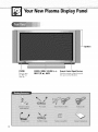
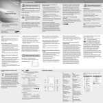
YourNew PlasmaDisplayPanel
POWER
SOURCE,MENU,VOLUME(-,+),
PF@SS to turn
SELECT
(V,A),
the PDPon
and off.
10
MUTE
Remote Control Signal Receiver
Aim the remote control towards
this spot on the Monitor.
0
0
0
00
O
0 ExternalSpeakerOutjacks
Connect
external
to the video
output
0
l_ S-VideoInputjack
speakers,
Connect
or DVD
O PC(RGB)Inputjack(15pin)
Connect
O
jack
on your
PC.
O Component
Video Inputjacks (Y/Pb/Pr)
Component
1 inputs
are for 4801/480p.
Component
1080i.
2 inputs
are for
signal
from
an S-VHS VCR
Q AudioInput (Video/Componentl/2/PC(RGB))
jacks
Connect
a audio
such as VCRs,
480p/720p/
signal
from
PC or DVD
external
sources
players.
0 ServiceJack
Connect
0 VideoInputjack
Connect
a video signal
from external
such as VCRs or DVD players.
a S-Video
player.
sources
the
RS-232C
input jack
to your
PC.
0 Power Inputjack
Connect
the supplied
power
cord.
11
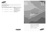
RemoteControlButtons
0
Power button
Turns the PDP on and off.
ID Numberbuttons
_) Display button
Press to display information on the PDP screen,
0
Menu button
Displays the main on-screen menu.
_1CH (Channel)andVOL(Volume)buttons
Channel
and Volume
bultons are used
menu items in the menu mode.
for
selecting
_]1 Mute button
Press to mute the PDP sound.
0
P,Mode button
Adjust the PDP picture by selecting one of the preset
factory settings (or select your personal, customized
picture settings.)
Q Aspect button
Press to change the screen size,
0 Mode button
Selects
remote
a target device to be controlled
by the AKAI
control
tie,, VCR, Cable,
or DVD players).
_) Clock Display button
Press to display clock on the PDP screen,
_) Source button
Press to display all of the available video sources
tie,, Video, S-Video, Component1, Component2,
PC(RGB)),
_) Joystick button
Use to highlight on-screen menu items and change
menu values,
_)
Still button
Press 1o pause
the current
screen.
_) PIP button
Activates picture in picture.
_) Source selection buttons
Press to directly select Video, S-Video, Component1,
Component2 or PC(RGB),
12
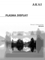
_)VCR
control buttons
Controls VCR tape functions: Stop, Rewind,
Play/Pause, Fast Forward.
SETbutton
Used
during
work
compatibly
setup
DVD,
etc.)
of this remote
with
other
control,
devices
so that
it will
(:able
box,
(VCR,
@
@
_) Clock set button
Press to set clock.
_)
PIP control
Source
S.Sel
Locate
:
:
buttons
Press to select one of the available
sources for the PiP window.
Press to select the Audio
:
Press to move
signal
(PIP or Main).
the PIP window
on the screen.
_) PC control buttons
Auto Adjust
Scaling
Zoom/Pan
_) &Mode button
Adjust the PDP sound by selecting one of the preset
factory settings (or select your personal, customized
sound settings.)
Sleep button
Press to select a [)reset time interval for automatic
shutoff.
Slide the back cover
to open the battery
Install two AAA size batteries. Make sure to match the
compartment
of the
remote control
"+"
and
"-" ends
of the
Slide the cover
place,
back
into
bat-
teries with the diagram
inside the compartment.
RemoteControlOperationRange.
You car/use
from
your
the left and
remote
control
right sides
within
a distance
of the remote
control
of 23 feet and
receiver
an angle
of 30
degrees
of the monitor.
13
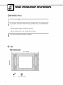
Wall InstallationInstructions
@ Installation
Notes
Do not
install
To
protect
places:
the PDP in any location
the performance
other
of the PDP and
• Do not
install
next
to smoke
and
• Do not
install
in an area
subjected
• Do not
install
in an area
subjected
• Do not
install
near
Use only
recommended
or around
parts
any
and
fire
to high
heating
components.
34.61 inches
14
holder
prevent
walls.
problems,
to vibration.
Wall attachment panel
Insulation
vertical
detectors.
@ Parts
bolt
than
voltage.
apparatus.
avoid
the
following
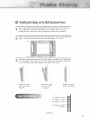
0 Installing
theDisplay
ontheWall
Attachment
Pand
See stability
the drawing
the where
wall attachment
14 tois check
the
of the ofwall
the PDP is panel
to be shown
installed, in page
If the wall
not
enough
strong
Fix the wall
figure:
to support
attachment
Fixing
bolts
the PDP, strengthen
panel
on the
must protrude
Using
wall attachment
0 to 20thedegrees.
The angle panel,
can
each,
using
the angle
control
wall
from
the wall
using
the
wall
before
bolts
as shown
appox.
0.6
for
installation,
in the following
inches.
youset may
of the display
from
be
in 5 adjust
stages thewithangle
5 degrees
of distance
holes
on the sides
of the panel.
IIII
When
the angle
has been set to 5
When
the angle
has been set to
degrees.
15 degrees.
ii!iiii
When
hasn't
the panel
been tilted.
5
10
15
2O
Continued...
15
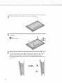
Remove
four
large
screws
from
the
rear
side
of the
display,
[
iiiiiiiiiiiii!iii%iii?ii!%i_i_
Insert the
bolts
and
insulation
sJnto the four
screwholes
as shown
in the
follow-
ing figure:
0 _olt
0
Insulation
holder
0
-0
II
Put the
insulation
pointwallprotruding
the rear
or the
displaya little
in
the
groove
on the rubber
top of the
attachment from panel.
Lift top
up the
display
bit so that
the insulation
rubber
display
is put in the groove
(Do not
lift the
be taken
off.
display
with
point
at the
any
at the
bottom
pressure.
bottom
or the wall
of the rear
attachment
The insulation
rubber
)
0
16
side of the
panel.
at the
top
may
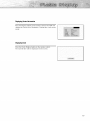
@ Separating
theDisplay
fromtheWall
Attachment
Pand
Remove
bottom
wall
the
fixing
of the
attachment
Lift the display
bolts
display
from
a small
both
sides
amount,
(left and
to separate
right)
the
of the wall
insulation
attachment
holder
point
panel.
from
Lift and
the bottom
pull
the
of the
panel.
and
separate
the
insulation
holder
point
from
the groove
on top
of the wall
attachment
panel.
0
17
OnandOff
Turning
the
Turning
the[v]onitor(PDP)
OnandOff
Press the
Power
The PDP will
features.
You can
button
on the remote
be turned
on and
also use the
Power
control.
you will
button
be ready
on the front
to use it's
or the
PDE
Notes:
•
If your
Monitor
pressed:
mode
isn't
turned
on when
Press the MODE
has been
button
chosen
the power
to check
_
button
is
ir the Monitor
).
Viewing
theMenus
andDisplays
Your
PDP has a simple,
venient
and
features.
easy-to-use
fast to use features
menu
system
that appears
on the PDP. Your
PDP also
Viewingthe Menus
With
the power
remote
The Video
2
menu.
menu
menu.
down)
the Menu
after
(left,
selected
(_)
menus
automatically
press
(up,
or use the
screen
Menu
menu
button
appears
on the
on the screen.
is selected.
Use the joystick
Use the joystick
On
press the
The main
Use the joystick
change,
18
on,
control.
button
right)
disappear
about
items
in the
to display,
items.
button
button
to move
button
to enter
from
thirty
on your
items
in the menu.
the screen
seconds,
remote
or you
control
can
to exit
on the PDP screen.
lets you display
the
This system
the status
or many
makes
it con-
or your
PDP's
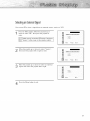
DisplayingStatusInformation
Press the
display
Display
the Screen
button
size,
on the
remote
Resolution,
control.
Current
The PDP will
time,
and
screen
mode.
Displaying Clock
Press the Clock Display button on the remote control.
The Current time will be displayed on the screen.
19
(Connecting Speakers / Receiver)
Connecting Speakers ..........................................................
22
Connecting
a VCR/Cabie
Connecting
a DVD
Box ......................................................
Connecting
a Set-Top Box ..............................................................
......................................................................
23
24
25
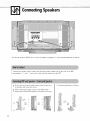
Connecting
Speakers
Yr External
speakers
Connect
the speaker
matching
the
MUST
"+"
and
audio
have
a power
cable
"-" ends
handling
to the external
of the (:able
Fix the bracket
onto the guide pole
of speaker
and fasten the screws.
After removing
the three screws
thespeaker
and the PDP together
with
located
#!iiiili
"®_
Guide
Guide
22
m
®
speaker
of 7 watts
output
the
diagram
on the
rear
on the PDP, clamp
and fasten the screws.
pole
__
capability
jack
on the
minimum(impedance
on the rear
of the
8ohm).
PDP,
PDP.
• Connecting
Speakers
to Stands.
Connecting
a VCR/CableBox
PDP
Video/decodificador
de cable
Connect
Video/S-Video
cable between
the Video/S-Video
box and the Video Inputjack
on the PDP.
• For better
video,
Connect
an Audio
Audio
Inputjacks
use an S-Video
cable
(Video)
Outputjack
on the VCR/Cable
cable.
between
the Audio
on the PDP.
Outputjacks
on the VCR/Cable
box and
the
Videotape Playback:
1. Turn on PDP and press the Video or S-Video(if S-Videojack is connected.) button on your
remote control.
2. Turn on your VCR, insert a videotape and press the Play button.
23
Connecting
a DVD
PDP
DVD
Connect
a Video (:able between
the DVD Output
Video Input (Y,P_,P,) Input jacks
on the PDP.
Connect
an Audio
jacks
(Component)
(:able between
on the PDP .
the Audio
jacks
Output
on the DVD
jacks
and
on the DVD
the Component1
and the
Play to DVD:
1. Turn on PDP and press the Component button to select the Component1
2. Turn on your DVD, insert a DVD disc and press the Play button.
• For an explanation
24
of Component
video,
see your
DVD owner's
instructions.
mode.
Audio
Input
Connecting
aSet.Top
Box(480p/720p/108
PDP
Receptor de DTV
Connect
a Video cable between
the Set-Top Box (Y, Pb,Pr) Output
the Component
2 Video Input (Y, Pb,Pr) Input jacks
on the PDP.
Connect
an Audio
(:able
Input jacks
(Component)
between
the Audio
on the PDP .
Output
jacks
jacks
on the Set-Top
on the Set-T op
Box and
Box and
the Audio
ToWatchDTV:
1. Turn on PDP and
2. Turn on your
press the
Component
button
to select
the Component2
mode.
DTV receiver.
• For an explanation
of Component
video,
see your
DTV receiver
owner's
instructions.
25
PictureControl
Customizing
the Picture
Using Automatic
Viewing
Changing
Freezing
................................................................
Picture Settings
the Pictureqn-Picture
the Screen
Size
....................................................
28
29
..........................................................
30
............................................................
33
the Picture ......................................................................
34
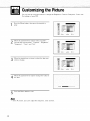
Customizingthe Picture
You can use the on-screen menus to change the Brightness, Contrast, Sharpness, Color, and
Tint settings of your PDP,
Press the
enter.
Menu
button,
then
press the joystick
Movewillthealso
joystick
left items
or right"Contrast",
to select
You
see the
"Sharpness",
Move
wish
"Color"
the joystick
Press the Menu
28
"Custom".
"Brightness",
"Tint".
up or down
to select
left or right
to change
the item
you
to change.
Moveitem.
the
the joystick
•
and
to
In the PC mode,
button
you can't
the value
of
to exit.
adjust
the sharpness,
color
and
tint.
UsingAutomaticPictureSettings
Your PDP has automatic
Press the
enter.
Move
Menu
button,
thejoystick
"Standard",
"Custom"
to select
or "Dynamic"
"High,"
settings
press thejoystick
left or right
"Mild",
• You can select
then
picture
"Middle,"
that
allow
you to adjust
the video
display
easily.
to
"Custom",
picture
setting.
"Low,"
or
in PC mode.
Press the Menu
button
to exit.
29
Viewingthe Picture.in.Picture
Selecting
thePLP
Screen
Press the
Menu
select
"PIP",
then button.
press
Movejoystick
the joystick
the
to enter.up or down
to
Move the joystick
left or right to select "On'.
The PIP image will appear
in the corner of the screen.
i_i /
Press the
•
30
Menu
The PIP function
button
operates
to exit.
in PC mode
or Component2
mode
only.
_ s0u_
Selecting
anExternal
Signal
You (;an use PIP to view
a signal
from
an external
source,
such
as a VCR.
Press the
Menu "PIP",
button. then
Move
joystick
down
to select
pressthethe
joystick up toor
)
enter.
Move move
the joystick
up orleft
down
to select
"Source",
then
the joystick
or right
to enter.
/
..................... J
Move
signal,
the joystick
then
move
up or down
to select
the joystick
left or right.
an external
i
;/
Press the
Menu
button
to exit.
31
Changing
theLocation
ofthePiPimage
Press the Menu button.
Move the joystick
up or
down to select "PIP", then press thejoystick
to
enter.
Move the joystick
up or down to select "[ocate",
then move the joystick
left or right to enter.
Move
want,
the joystick
Press the
32
Menu
to move
button
the
to exit.
PIP screen
where
you
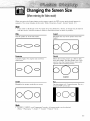
Changingthe ScreenSize
(When
entering
theVideo
mode)
When
you press the
sequence.
•
If you watch
onto
Aspect
The screen
a still
the screen,
button
displays
image
View
on the remote
in this order:
or the 4:3
the monitor
Wide,
mode
in Wide
for
control,
the
PDP's screen
Panorama,
a long
Zoom1,
time(over
or Panorama
mode
Wide
Zoom2
Sets the picture to 16:9 wide mode.
Magnifies
Zoom1.
should
2 hours),
an image
as much
as possible.
the size
appear
Stretch,
of the
in
4:3.
may
picture
be burned
more
than
ho4
ooo
Panorama
Stretch
Converts
regular
widescreen.
4:3
aspect
ratio
screen
to
Moves
show
the Zoom2
the bottom.
picture
up a little to fully
Use this picture
want to view the Zoom2
captions
when watching
IoO
size
picture along
movies.
if you
with
4:3
Zoom1
Magnifies
mode
Zoom2,
the picture vertically on screen.
Sets the picture
to 4:3 normal
standard
PDP screen
size.
mode.
lhis
is a
!° °!
o0o
Note
•
In VIDEO,
(Wide
-*
S-VIDEO,
Panorama
and
-*
Component1
Zoom1
-*
modes,
Zoom2
-*
all screen
Stretch
-*
modes
can
be selected.
4:3).
33
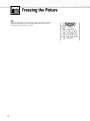
Freezingthe Picture
Still
Press the Still button on the remote control to freeze a moving picture. Press again to cancel.
34
SoundControl
Customizing
the Sound
Using Automatic
................................................................
Sound SetUngs ....................................................
Using the Surround
......................................................................
36
37
38
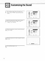
Customizingthe Sound
Press the
down
Menu
button,
to select
Move
"BOUND",
the joystick
then
up or
press the joystick
to enter,
Move
thejoystick
left or right
also
items
You will
"Balance"
Move
wish
Move
see the
and
the joystick
"Custom",
"Bass",
"Surround",
up or down
to select
the item you
left or right
to change
the value
to change.
thejoystick
the item.
Press the
36
to select
"Treble",
Menu
button
to exit.
of
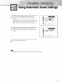
UsingAutomaticSoundSettings
Press the
Menu "SOUND",
button.
Movethenthepress
joystickthe joystick
up or
down
to select
to enter.
Move
the joystick
"Standard",
left or right
"Music",
"Movie"
to select
"Custom",
or "Speech"
sound
setting.
Press the Menu
•
The Automatic
button
Sound
to exit.
Setting
function
doesn't
operate
in PC mode.
37
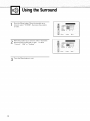
UsingtheSurround
I)ress _he Menu
down
to select
button,
"SOUND",
Move
the_oystick
then
up or
press the joystick
to enter,
Move
then
the joystick
move
"Concert",
Press the
38
up or down
the joystick
"Hall"
Menu
or "Stadium".
button
to select
left or right
to exit.
"Surround",
to select
8ass
_
• B_Lance _
5o
a
ii:_¸¸ i
£
;!!i: i_iii £
i}
ii
i_
i_:_ i
A
?
I;¸_' A
iiiii i}
i
Time Setting
Setting the Clock
.....................................
Setting the Sleep Timer
Setting the Timers
.................................
....................................
40
41
42
Settingthe Clock
This PDP has a built-in
remote controh
Press the
down
clock
that will
Menu
button.
Move
to select
"TIME",
then
appear
on screen
the joystick
when
you press
the Clock
Display
button
on the
up or
press the joystick
to
enter.
Move
the joystick
joystick
move the
hour.
left oror clown
right to
up
to select
select
hour,correct
then
the
_ o_lime
Sleet, _mer
_
Move thejoystick
thejoystick
move
minute.
left oror down
right
up
to
to select
select
minute,
the
correctthen
Move
move
left or right
up or down
to select
to select
"AM",
"AM
the joystick
the joystick
_t
then
or
"PM".
•
If you want
to display
the joystick
down
move
the joystick
Press the Menu
4O
the
to select
right.
button
to exit.
Clock
"Clock
on screen,
move
Display",
then
12: oa A_ o_
(
_ ClPc_DE_Pla'J
O;f
I
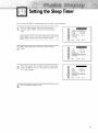
Settingthe Sleep Timer
You can set your
PDP to automatically
Press the
Menu "TIME",
button.
down
to select
turn off after
a preset
interval.
i
Move press
the joystick
up orto
then
the joystick
I
enter.
:::?i:0_,,,0:i,,
0,!
Move the joystick
Timer".
iii_ ¸ I
up or down to select "Sleep
Movefor the
left oron.rightTheto interval
select the
time
val
the joystick
PDP to stay
ranges
10 to 360 minutes.
interfrom
@
_,_
I
_ On time v0 ullle
.......:::
Press the
Menu
button
li
10
t:i
!
to exit.
41
Settingthe Timers
This PDP can be set to turn on or off automatically
at specific
timers,
previously.
you must
set the PDP's
Settin 9 the On/Off
(:lock,
as described
times
that you choose.
Before
using
the
Timer
Press the Menu button. Move the joystick up or
down to select "TIME", then press the joystick to
enter.
Move move
the joystick
up orleft
down
to select
then
the joystick
or right.
Move
move
hour.
the joystick
joystick
the
left oror down
right
up
"On
time",
to
then
to select
select hour,
the correct
iii
¸¸I
;_[ _
_ Off time
2
!8 ................
Sleep _mer
Move
the joystick
left or right
move
the joystick
up or down
the joystick
joystick
the
left oror down
right
up
to select minute,
to select the
_
t] A_
OR
O_
I',
_,
then
correct
minute.
Move
move
toto select
select "AM",
"AM"
then
or
"PM".
_
On time volume
r_ Sleep Timer
sh_
42
10
I
0 g
[
_,
Move
move
thejoystick
the
joystick
left oror down
right
up
If you to
want
to set
Off Time,
down
select
"OfftheTime".
Set the "Off
•
Time"just
If you want
turns
time
on,
volume".
volume
level
Press the Menu
the joystick
Move
the
you want
button
level
down
joystick
when
then
move the joystick
as you set "On
to set the volume
move
to
to select
select "Off",
"On".
the
Time".
when
the
to select
right
PDP
"On
to set the
PDP turns on.
to exit.
43
Connecting
PCandOperation
[_
Connecting
Adjusting
to a PC ......................................................................
46
the PC Scleen ................................................................
50
Changing
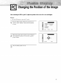
the Position
Changing
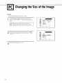
the Size o[ the image
Enlarging
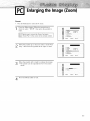
the image
Moving
o[ the hTlage ................................................
(Zoom)
the Zoom Picture
Picture ©uality
Information
Adjustment
....................................................
..........................................................
51
52
53
..............................................................
54
............................................................
55
..................................................................................
Power Saver (PC mode only) ..........................................................
58
59
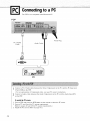
Connecting
to a PC
This PDP is not compatible
with
Audio
Cable
Macintosh
PC.
PDP
Power
PC (15pin)
Plug
Cable
PC
Connect
a PC (15pin)
cable
(15p D-SUB) on the PDP.
• For an explanation
Connect
a Audio
on the PDP.
between
of Component
cable
between
the
video,
the Audio
Video
Outputjack
see your
Output]ack
on the PC and the
PC owner's
instructions.
on the PC and the
Audio
To watch the PC screen:
1. Turn on PDP and press the RGB button on the remote to select the PC mode.
2. Turn on PC and check for PC system requirements.
(Refer to pages 48 and 49 for PC system requirements.)
3. Adjust the PC screen. (Refer to page 50.)
46
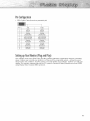
PC Inputjack
Input
(PC)
PinConfiguration
• 15Pin
Signal
Cable
_#, No
_C
/
(based
on
protruded
IN
_C OUT
Red {_}
2
Blue
4
5
6
Ble
(obq
{G i Gro
Ground
ng
Red
ndit_g
Green
IBI Grounding
Sync
G¢ound_ng
!3
HO_lZOatal
14
Vertical
/5
Clock
ng
IR) Grounding
IG} Glean4
GIoun_
ng
ng
Resewed
Sync
Grounding
Data
IB}
f_g IDDCI
Blue/B}
Rese red
]2
(G}
Blue
Ground
Re{_ (R} Gr0und
Green
1/
(8)
Grour,ding
8
/0
Greel_
Grounding
Z
9
£ed (R)
Green/G)
3
pin)
Grounding
Ground
(D_C I
ng
Data (DDC}
sync.
Ho_ zontal
sync.
Ve
DDC I
sync.
ical sync.
Clock
{DDC)
Setting
upYour
Monitor
(Plug
andPlay)
Our adoption
of the new VESA ('_ Plug and Play solution
setup. It allows
you to install your monitor
in a Plug and
eliminates
complicated
and time
Play compatible
system,
without
setup
identify
hassles
and
confusion.
Your
PC system
can
easily
display.
This monitor
automatically
tells the PC system
using Display
Data Channel
(DDC) protocols.
and
its Extended
configure
Display
itself for
Identification
consuming
the usual
use with
data
your
(EDID)
47
How
toSetupYour
PCSoftware
ONind0ws
0nly)
The Windows
your
PC will
display-settings
probably
ticular
video
apply
in almost
card,
for a typical
be different,
But even
all cases,
if your
computer
depending
actual
(If not, contact
screens
your
are
upon
shown
your
look different,
computer
On the
the
control
and
Select
"Settings"
The two
tings
for these
•
Size
•
two
(sometimes
640
x 480
Color:
screen
million
for
settings
or "60
the
Continue(]...
48
Hz."
dialog
will
in the following
tab
Panel.
appears,
dialog-box
that apply
on
appear.
dialog-box,
the
"colors."
variables
click
will
in the display
and
color
PDP-PC
inter-
Tile correct
set-
are:
"resolution"):
(might
dialog
dialog
option
box,
Otherwise,just
box.
also be expressed
colors")Shown
"Display"
If a vertical-frequency
play
on
par-
information
-_ Control
screen
called
your
pixels.
"24-bit"
as "16
select
panel
key variables
are "resolution"
screens
and
sebup
Settings
a display
face
actual
Dealer,)
screen,
"Display"
the
basic
or AKAI
: Start _
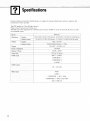
the
of Windows
the same,
windows
When
........ I:'¢' 'ti,%:,:t,"iJ..........
However,
version
manufacturer
sequence
_i
below,
particular
the
at left is a typical
box.
exists
on your
dis-
correct
value
is "60"
click
"OK"
and
exit
Notes;
Both screen
below
position
shows
all
an(:] size
of the
will
display
vary,
modes
depending
that
on the type
Vertical
Video
of PC monitor
and
its resolution.
The table
are supported:
Horizontal
Vertical
Horizontal
polarity
polarity
Dot X Line
signal
Frequency(Hz)
640
X 350
640
X 400
720
X 400
640
X 480
IBM PC / AT
Compatible
800
X 600
1024
•
The interlace
•
The PDP operates
mode
X 768
is not
Frequency(KHz)
70,086
31469
N
85.080
37861
N
P
P
85.080
37861
P
N
70,087
31469
P
N
85.039
37927
P
N
59,940
31469
N
N
72.809
37861
N
N
75.000
37500
N
N
85.008
43269
N
56,250
35156
N/P
N/P
60,317
37879
P
P
72.188
48077
P
P
75.000
46875
P
P
85.061
53674
P
P
60,004
48363
N
N
70,069
56476
N
N
75.029
60023
P
P
84,997
68677
P
P
N
supported.
abnormally
if a non-standard
video
format
is selected.
Notes;
•
When
•
Depending
(and
this PDP is used
on the
depending
Check
your
•
If a vertical
•
In some
•
as a PC display,
manufacturer,
on your
PC instruction
an(:] horizontal
particular
version
book
for information
frequency-select
about
mode
connecting
exists,
select
Source
button
Connect
port
to the monitor
(over
appear
16 million
colors).
different.
of Windows).
off (or if the PC is disconnected).
If so, press the
Also, make sure that the PC is connected.
a PC monitor
(such
might
appear
only
signals
is supported
screen
might
might
abnormal
color
as stripes)
signals
cases,
24-bit
y our PC display
output
while
your
60Hz
PC to a PDP.
(vertical)
and
on the screen
when
to enter
viewing
the VIDE()
the PC screen.
31.5kHZ
(horizontal).
the PC power
is turned
mode.
(Otherwise,
random
appear).
49
Adjustingthe PCScreen
Adjusting
theR,G,B
Preset:
•
Press the ROB button to select the PC mode.
Press the
enter.
Menu
button,
then
press thejoystick
to
Move the joystick
or down
Control",
then moveup thejoystick
to left
select
"Color to enter.
or right
Move
thejoystick
to select
want
to change.
up or down
the item
you
Move
thejoystick
or left gauge
to change
the value
the item,
using the right
on-screen
as your
guide. of
Press the Menu
5O
button
to exit.
Changing
thePosition
of theImage
After connecting
the PDPto your PC,adjustthe positionof the screenif it is notwell-aligned.
Preset:
•
Press the RGB button to select the PC mode,
Press the
Menu "SETUP",
button.
Move
down
to select
then
to enter.
the joystick
up or
press
the joystick
Move adjust
the joystick
left or ofright
to select
"Position",
then
the position
screen
by using
the
joystick
button.
Press the Menu
button
to exit.
51
Changingthe Sizeof the Image
Preset:
•
i
Pressthe RGB button to select the PC mode.
Press the
Menu "SETUP",
button.
Move
joystick
up or
down
to select
then the
press
the joystick
enter.
to
Move move
the joystick
up orleft
down
to select
"Scaling",
then
the joystick
or right
to select
"Wide"
or "4:3".
[]
3
52
Press the
Menu
button
to exit.
_ Zoom/Panmng
mlage
Lock
Enlargingthe Image Zoom)
Preset:
•
Pressthe RGB button to select the PC mode,
Press
Menu
down the
to select
enter.
Move
button.
joystick
up or
"SETUP", Move
then the
press
thejoystick
the joystick
ning",
then
up or down
move
thejoystick
Move
the joystick
• The picture
(:an
to select
to
"Zoom/Pan-
left or right
to enter.
left expanded
or right to 0
enlarge
be
to 10
theZoom
image.
in
mode.
Press the
Menu
button
to exit.
53
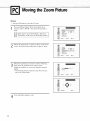
Movingthe ZoomPicture
Preset:
•
Pressthe RGB button to select the PC mode.
Press the
Menu "SETUP",
button.
Move
joystick
up or to
down
to select
then the
press
the joystick
enter.
_
Lmlguage
<
Scaag
_
Engtmtl
Wde
_.
_"
_ z00mP_nmna
/]_
_
Image Lock
I
J
Move
ning",
3
Move
then
Adjust
button.
the
thenjoystick
move
up joystick
or down
the
the joystick
up or down
move
the joystick
the position
to select
left
or right "Zoom/Panto enter.
to select
left or right
of screen
by using
• The Panning
feature operates
ture is in Zoom mode.
Press the Menu
54
button
to exit.
"Panning",
to enter.
only
the joystick
when
the
pic-
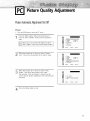
PictureQualityAdjustment
Picture
Automatic
Adjustment
On/Off
Preset:
•
Press the RGB button to select the PC mode,
Press the
Menu "SETUP",
button.
Move
down
to select
then
enter.
the joystick
up or to
press
the joystick
Move
Lock",
to or
select
left
right "Image
to enter.
the
thenjoystick
move
up joystick
or down
the
Move thethen
joystick
down
Adjust",
move uptheor joystick
The message
screen
and
"Auto
the
toleftselect
"Auto
or right.
in progress"
picture
adjustments
appears
on the
are automatically
activated.
Press the
Menu
button
to exit.
55
Frequency
Adjustment
Preset:
•
Press the RGB button
to select the PC mode.
Press the Menu button.
Move
down to select "SETUP", then
enter.
Move
lock",
thejoystick
then move
up or down to select "Image
thejoystick
left or right to enter.
Remove picture
noise
by moving
thejoystick
(If frequency
wiJJ appear
the joystick
up or
press the joystick
to
(vertical
stripes
left or right.
is not set properly,
vertical
on the
screen
stripes
on the screen.)
AU_ Adju_t_ffleat
€
I
Press the
56
Menu
button
to exit,
_'e
1_ Adj_sl
_ ExLt
....
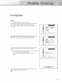
Fine
Tuning
(Phase)
Preset:
•
Pressthe RGB button to select the PC mode,
Press the
Menu "SETUP",
button.
Move
down
to select
then
enter.
the joystick
up or to
press
the joystick
Move
Lock",
the
thenjoystick
move
up joystick
or down
the
to or
select
left
right "Image
to enter.
Move
the joystick
up or down
Remove
picture
by moving
(If phase
noise
the joystick
(vertical
to select
stripes)
"Phase".
on the screen
left or right.
is not set properly,
the
picture
may
be
blurry.)
Press the
Menu
button
to exit.
57
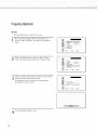
Information
Preset:
•
Pressthe RGB button to select the PC mode.
Press the
Menu "SETUP",
button.
Move
joystick
up or to
down
to select
then the
press
the joystick
enter.
Move
neous",
the joystick
then
up or down
move the joystick
to select
"Miscella-
left or right
to
enter.
Move
tion",
the joystick
then
move
up joystick
or down left
to or
select
the
right "Informato enter.
_
Press the Menu
58
button
to exit.
_ KeyL_k
_
O_
_
PowerSaver PCmodeonly)
This monitor
has a built-in
system
saves energy
certain
amount
of time.
card
installed
ture.
See the table
power
management
by switching
in your
your
This power
computer.
below
system
monitor
called
Power
into a low-power
management
system
You use a software
utility
operates
Saver.
This power
management
mode
when
it has not
with
a VESA
DPMS
installed
on your
computer
been
used
compliant
for
a
video
to set up this fea-
for details.
Table1, Power-savingmodes
Power-saving
Normal
State
Operation
Standby
Mode
Function
Suspend
Position
Mode
Mode
A1
Power-off
Position
Mode
A2
Active
Inactive
Active
Inactive
Active
Active
Inactive
Inactive
Video
Active
Blanked
Blanked
Blanked
Power
Green
Red Blinking
Red Blinking
Red Blinking
(1 sec
(1 sec Interval)
(1 sec
Horizontal
Vertical
Sync
Sync
Indicator
Interval)
Interval)
Notes:
•
This monitor
•
This occurs
when
•
For energy
conservation,
ed for long
automatically
moving
returns
the
to normal
computer's
turn your
monitor
operation
mouse
OFF
when
or pressing
when
horizontal
a key
and
vertical
sync return.
on the keyboard.
it is not needed,
or when
leaving
it unattend-
periods.
59
P
L
A
$
M
A
#
_
S
?
L
A
Y
?
A
_
L
E
FunctionDescriptionE_
Selecting
a Menu [dnguage
Setting the Multi
Control
Using the Key Lock
.............................
................................
...................................
SettiNg up Youl Remote Control
...........................
62
63
64
65
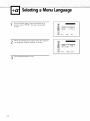
Selectinga MenuLanguage
Press the
Menu "SETUP",
button.
Move
joystick
up or
down
to select
then the
press
the joystick
10 enter,
i
_:
Move thejoystick
{eft or right to select the appropriate language:
English,
Spanish,
or French.
Press the
62
Menu
button
to exit.
_"
4_Adj
sl
[_ E>i{
II
II
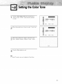
Settingthe ColorTone
Press the Menu
down to select
button.
Move the joystick
up or
"SETUP", then press the joystick
to enter.
Move
the joystick
Move
the joystick
up or down
left or right
Tone : Normal,
Warm1,
Press the Menu
button
to select
to select
Warm2,
"Color
Tone".
the Color
Coo11,
Cool2.
to exit.
Note
•
In the
PC mode,
you can't
adjust
the Color
Tone.
63
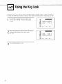
Usingthe Key Lock
When Key Lock is set to ON, the buttons (SOURCE, MENU, VOLUME, SELECT, MUTE, POWER) on
the front or the PDP will not operate. However, these buttons will operate when setting Key Lock OFF.
Press the
Menu "SETUP",
button.
Move
joystick
up or
down
to select
then the
press
the joystick
to enter.
Move move
the joystick
up orleft
down
to select
"Key
then
the joystick
or right
to select
"On"
or "Off".
Press the
64
Menu
button
to exit.
Lock",
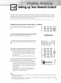
SettingupYourRemoteControl
This PDP's remote
properly,
Pressing
and
your
control
remote
can operate
control
the corresponding
control
#_oe;71e
whichever
remote
button
piece
corlttol
almost
can operate
on the remote
of equipment
lily
any VCR,
in four
lot
cable
different
control
you
box,
modes
allows
or DVD.
:Monitor,
After
it has been
VCR,
Cable,
you to switch
between
set up
or DVD.
these modes,
choose.
be comp,_'tble
wRi
,_,11DVD
fh_yets,
VCR
,_,rld C,_')le
box_,s
Setting Up the Remote to Operate Your VCR, Cable box, or DVD player
Turn off your VCR. (or Cable box, DVD player.)
Press the
MODE
(or Cable
box,
button
DVD)
Press the Set button
4
the
number
enter
three
digits
code
listed
on page
of VCR
first digit
(If more
than
one
on if your
remote
box,
repeat
DVD
DVD
player).
If no other
your
codes
player:
on the
box,
D,)
_C_ifCC)
CC) CC)
I
I
DVD)
for your
player).
Make
even
if the
try the first one.)
remote
control.
DVD player)
does
2, 3, and
for
089
is listed,
player)
steps
listed
DVD
VC£
control,
box,
of the code,
is set up correctly.
DVD
codes
through
:tr
VCR
control.
remote
(or Cable
box,
digits
button
(or Cable
up,
on your
64 of this manual
code
Your VCR
Cable
that the
is a "0".
Press the Power
5
buttons
three
sure
PDP's remote
of the VCR
(or Cable
sure you enter
make
on your
Using
brand
and
LED is illuminated.
of VCR
are listed,
000
try
box:
through
not turn
(or
of the other
(or Cable
each
0000
turn
VCR
on after set
4, but try one
brand
(or Cable
should
If your
box,
code,
000
through
077,
008).
Note_
•
•
When
your
remote
still operate
your
When
remote
your
Play/Pause,
control
is in "VCR"
mode,
is in "Cable
box"
the
VCR control
buttons
(Stop,
REW,
Play/Pause,
FF)
VCR.
control
FF) still operate
your
VCR.
or "DVD"
mode,
the VCR control
buttons
(Stop,
REW,
65
RemoteControlCodes
VCR
Codes
A_/n75r;*l
Aiv, a
Aka
017 022
023
Audio Dynamics
gel1 @ I iowe//
006
079
KI/4
IG
027
0] 5
030
0] 4 0] 6
002
Broksonic
010
Cai_dle
007
Ca_mort
Ciliz_n
046
052
(}09¸ 0! 3,045
008
046
(153
052
007
009 0!3, 04_
(_o/orl3me
Craig
Cur_is-Mathes
007
000007,/!08,0/4,
015 046, 053
Daewoo
DBX
013
064
031
015
Ma_,na_c,x
MaranEx
008 029 053, 056
002, 008, 014, 0! 6,
Maria
1)29 03(!¸ 0÷6, i)6¸[
009
(}08
067
Mid}and
Memorex
M(;A
008
000
M//rJI_>mery
D_nalech
Electrot!ome
015
027
MIC
M_lti_ech
0_ 0_] 04_ 047 _
Fisher
002,012
057 0_ _5 _7 0_ 070
018 01g 043,0%
058
Fur/ai
(;E
0//0¸ 007,/)08¸
032
Go _d_:o
Harn7a_ Fa_o_
HJ_achi
/ns!a_t
Replay
JC Permey
002
]CL
008
JVC
Kenv, ood
Cable
007
014
_fi!co
051
030
053
04d
Quarlz
Quasar
002, i)14¸ 088 08_
(}02¸ 0!4, 016 03(}¸ _6
Radio
015
007, 015
031,032
014 0_
030
_6
0(_1 0_4
(/08¸ (}_3,075,
S}_ack/Rcalist
009 012,015,
03_
040
006
1)06
07;
003, 035
046
Res_'r_ h +
008
014
007, 008
027
005
035
warcl
007
®2
Phi/ips
P_or_eer
Port/ariel
ProSca_
005
Sa_4_,n
Sa_st_i
005, 007
008,028,
035
054
037
069
007¸0/3¸022¸032¸042¸077
016
002 012
013 041 049 0{}8
005, 009,012
018,
002
Sharp
Shirt,ore
019
035
043
0a;8
006
01;
027
02d
030
031
045
053
Si_nal_t_
01
SoT_y
Sylva_7ia
Symp]_onic
(138
029
0_3
056
0/
002
01
00 c)
008, 015
0] 7,026
Tandy
Tashiko
Tatunf4
Teac
l_cimics
I o_b_
Tol_visio_
(}29, 0_3, 056
Unilech
008
016 033
044¸¸ 045
029
050
052
000
Vector
Viclor
002
008, 053
Wards
030
069
008
0]_
030
008
009
015
005, 013
019
048,0-19
007,009
T_e_nika
IMK
005
002,006
008,
(}27¸ 045 053
g
Sa_yo
Scot!
Sears
008
019
000
021
0d_
1107
Resean
h
014
_deo
Co_cepls
_deosomc
016
016
014¸¸ 016
007
005 006, 007, 008 00-3,
0¸[2¸ 0!3, 015 027 03] 035
¥ama}la
Y_it h
002,014
016
01 l, 017
030
026
046
07 c)
Box Codes
Am'isioT_
CaNesla
Eagle
Easlei_:
007
007
008
008
NSC
007
008
002
Osk Sigma
Inl
Genen!//ns!_ume//t
GI
_lilachi
}ermid
Macom
030
003
015,023,024
069
048
037,
(146
0_3
007 008, 0/9
02!)¸ 032,033,040
021
041
Codes
Philips
P_oscah
R(Z
]oshiba
Par_aso_ic
5o_y
Sams_ng
001
002
002
003
004
008
000
016
Pal_asonic
Philips
036, 067 068
012,013,034
00_,, 005 0_5,023,
024
02_, 030 036, 0-%, 062 065
037 043
Mag:_avox
026 028
Oak
_6
004, 005,
025
Hamlin
DVD
I_n{ax
f_n_ex
01_f 03_5 036
005
()pl_mus
Panasorfic
015
0_3
005
016 030 035
002 0!4, 016
NEC
0/)9, 0!2, 015
027
032
Mi_ola
Milsl_bishi
RCA
060
[og_k
[.g/
014
012
_8 00_ 0i0 013 0i5 {20 0B 027
0_6
015
MEI
045 076
0/4¸016
014
Lloyd
Dimensia
Emerson
66
073
009
Pi{_eer
009
Sigl_atul_-
038
S]_cer
SIaT_om
0/6
00302703906],
073
Slargale
074
007,00801902!,026,
028029032033040041
018020,044,074077
ILmdlek
RCA
0071008
000,027066
Re_il
R.'g_ncy
hA
003,012013
002033
070,07]072
Samsung
044003022,063064
046
027
046
2000
058
S_v,mia
Texscal_
Eocom
_/_lika
Universal
View_le_
\Vamer
Z_:ni_}_
01 ] 059
011 059
0!7,021
049
0_0 0_5 073
031,032
04[
0_1,052
007,(}08,019,021,02d,
028, 029
Amex
032,033,
0"/0 041
044
01_t 0"*2,057
075
0t_,
076
ii!_
15
iii_Jii ii!_
iii:_
i!i
ii:_¸
ii!_ ii_
ill:_¸¸ ii!_
iii_i_ i:ii: ii
Appendix
Troubleshooting
Care
............................................................................
and Maintenance
Specifications
................................................................
..............................................................................
68
69
70
Troubleshooting
Before
time
you call
and
a service
technician,
please
scan
this
list of problems
Problem
Poor
The power
blinking
Check
indicator
Js
]he
amber
Remoie
operate
the
The monitor
There
mcalror
Check
control
does
no[
turn
is no screen
The image
[ne
on
IS using
sure
Check
picture
blinks
68
is too
its power
managemem
Press the "Mode
Make
image.
you
au[[on
managem÷,lt
Utility
[o put your
sys[err
on your
remote
computer
control
in the
mode
the wall
outlet
[o see [nat oo[n
is working
the monitor
ana
[ne source
are pluggecl
on
Ilgn[ or
Adjust
the Brightness
_[oo
large
Aujust
the Size
"Check
nks on the screen
The message
the
save
or Contrast
settings
or
settings
small
The message
o
It may
dark.
The image
too
solutions.
connections
the power
Monitor"
monitor
won't
all wire
1 aria [urnea
too
possible
PossibleSolution
Dlcture
Your
and
money.
switches
"Check
on me screen
picture
switches
TemD
and
then
]'he
PDP is overnea[ea
Power
off the
PDP and
e[ ir cool
for
While
OFF
Fan
and
O[[
]'he
ther
cooling
au[norlzec]
fan
of the PDP ma'_ have
service
cemer
a oroblem.
Contact
an
a
Careand Maintenance
With
proper
the maximum
care,
your
performance
PDP will
give
you many
from
your
PDP.
years
of service.
Please
follow
these
guidelines
to get
IdentifyingProblems
•
Do not put the
PDP near extremely
•
Do not put the
PDP near appliances
•
Keep
•
Do not place
the ventilation
Liquids
• Do not place
openings
hot, cold,
that create
humid
or dusty
magnetic
places.
fields.
clear.
the PDP on a rough
and
slanted
surface,
such
as cloth
or paper.
liguids near or on the PDP.
Cabinet
•
•
•
Never open the cabinet or touch the parts inside.
Wipe your PDP with a clean, dry cloth. Never use water, (:leaning fluids, wax, or chemicals.
Do not put heavy objects on top of the cabinet.
Temperature
•
If your PDP is suddenly moved from a cold to a warm place, unplug the power cord for at least two
hours so that moisture that may have formed inside the unit can dry completely.
69
Specifications
Exterior
design
performance
and
This PDP applies
(Note:
Class
product
specifications
are
subject
to change
without
prior
notice
to Class
B system
B digital
is for home
This PDP has been registered
as residential
areas.
Dimensions
Display
Remote Control
Weight
Display
Remote Control
device.
use.)
for residential
use in terms
of EMI. So it can
be used
in all areas
as well
10388 (W) X 89 (D) X 635 (H) ram; 4090 (W) X 350 (D) X 25 00(H)inches
54 (W) X 31 5 (D) X 220 (H) mm ; 213 (W) X 1 24 (D) X 866 (H) inches
32kg ; 70 551bs
15% (including batteries); 0 331bs
100-240V-, 50/60Hzr 4A
Voltage
Power Consumption
Number of Pixels
310 Watts
852(H) x 480(V)
Screen Size
106 Cm/42 inches
AUDI O input
VIDEO / S-VIDEO
COMPONENT 1
COMPONENT 2
PC (RGB)
output
7W + 7W (8 _2)
VIDEO
S-VIDEO
COMPONENT 1 - 480i / 480p
COMPONENT 2 - 480p/720p/1080i
RGB : D-SUB15P
7O
the
PDP4290
Model
AUDIO
to improve
of this product.
Memo
71
BN68-00394A-00(ENG)