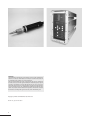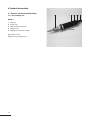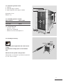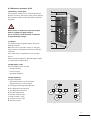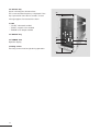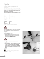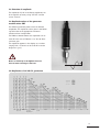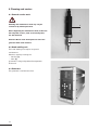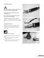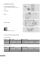
1
Operating Manual
Hand Welding Unit
HW35-3
English
with generator SL35
Disclaimer
The information in this brochure corresponds to our current state of knowledge.
However, it is not to be understood as a warranty for certain characteristics or
for suitability of the products for certain applications.
Our general contractual terms apply in this regard, and reference should also
be made to these terms with regard to liability. No industrial property rights of
any kind are granted to the user along with this brochure, nor are any assurances
made with regard to a licence. Corresponding separate agreements would be
necessary for this purpose. The suitability of the products for particular applications may only be checked with our own specialists. The German version of
the brochure is binding with regard to accuracy of the information given.
Copyright by RINCO ULTRASONICS AG, Switzerland
Version 2.0, gb, Art.-No. 35551
2
Note
This operating manual must be read and observed
before unpacking and initial operation of the
unit.
The unit may exclusively be operated and
serviced by persons who know the operating
manual and the applicable regulations with regard
to industrial safety and prevention of accidents.
Repairs may only be carried out through official
and certified RINCO departments.
Unit-specific information
Adhesive hand unit
Adhesive generator
Agency
3
Table of contents
1 Explanation of symbols and signs
6
2 Safety information
2.1
General information
2.2
Intended use
2.3
Improper use
2.4
Important instructions
2.5
Personnel qualifications
2.6
Installation of unit
2.7
Operation
2.8
Noise emissions
2.9
Warranty statement
7
7
7
7
7
7
7
7
8
8
3 Transportation
3.1
Acceptance of delivery
3.2
Damage during transit
3.3
Positioning of the unit
9
9
9
9
4 Product information
4.1
Product overview/technical data
4.1.1 Hand welding unit
4.1.2 Ultrasonic generator SL35
4.1.3 Available generator modules
4.1.4 Connected loads
4.1.5 Cooling (accessories)
10
10
10
11
11
11
11
5 Control and display elements
5.1
Hand welding unit
5.2
Valve box (optional)
5.3
Ultrasonic generator SL35
12
12
12
13
6 Initial operation
6.1
Choice of location
6.2
Assemble and connect unit
6.3
First welding
15
15
15
15
7 Retooling
7.1
Basic setting of the generator
for manual unit
7.2
Changing the horn
7.3
Selection of amplitude
7.4
Amplitude values of the generator
module series GM
7.5
Amplitudes of 35 kHz SL generators
16
16
4
16
17
17
17
8 Cleaning and service
8.1
General service work
8.2
Hand welding unit
8.3
Generator
8.4
Oscillator system
8.5
Screw connection
18
18
18
18
19
19
9 Internal unit service
9.1
Fuses for generator SL35
9.2
List of fuses for generator SL35
9.2.1 Fuses 230 Volt
9.2.2 Fuses 110 Volt
20
20
20
20
20
10 Error messages and troubleshooting
10.1 Error messages and troubleshooting
during start
10.2 Error messages from the generator
during operation
21
21
11 Service addresses
23
22
Important!
In case of enquiries concerning your unit please
state the exact type designation and the unit serial
number.
You will find these on the type plates (A) and on
the inside of the cover page of this operating manual.
The construction and switching mechanism of the
unit are consistently further developed and improved
and conform with state-of-the-art technology.
A
A
Foreword
We are pleased that you have decided to purchase
a RINCO product.
We are convinced that you will achieve a maximum
of economic efficiency and product quality when
using this unit.
The purpose of this manual is to provide the buyer
and user all necessary information for handling,
assembly, operation and care of the unit.
It is essential that the information and instructions
in this manual are observed in order to ensure that
the unit is constantly ready for operation.
5
1 Explanation of symbols and signs
Special attention must be paid to text sections with
the following symbols:
Set-up of the warnings
Note!
Information or operating instructions which are
especially important for interference-free operation.
Caution!
Describes warnings, the non-observance of which
can result in serious injuries or the risk of damage
to apparatus parts.
Danger!
Describes warnings, the non-observance of which
can result in death or very serious injuries.
6
2 Safety information
2.1 General information
The construction of this unit corresponds with
state-of-the-art technology and is safe to operate.
The individual modules and the complete unit
were tested by our quality control before delivery.
2.2 Intended use
This unit is exclusively determined for welding
suitable materials. Any other use or use beyond this
is deemed as improper use.
The manufacturer shall not be liable for damages
caused by improper use. The risk shall be borne
solely by the user.
This unit is intended for industrial use!
2.3 Improper use
•
•
•
•
•
•
Operation of the unit with insufficient
knowledge regarding operation, service and
supervision of the system.
Carrying out changes and extensions and
conversions to the manual unit and generator,
which could impair the safety, without the
approval of RINCO ULTRASONICS.
Undertaking changes to the control software!
Use of unsuitable materials.
Opening of the generator housing during
operation.
Access to live areas when the unit is
switched on.
2.5 Personnel qualifications
Work with the unit may only be carried out by
trained and instructed personnel. The responsibilities
of the personnel for operation, equipment, service
and repair are to be clearly stipulated by the operator!
The operator must ensure that only commissioned
personnel work on the unit.
Work on electrical equipment of the unit may only be
carried out by a skilled electrical worker according to
the rules of electrical technology. Only trained
personnel with knowledge and experience in handling pneumatics may work on pneumatic facilities!
2.6 Installation of unit
Danger!
Only carry out connection work to the unit when
the mains cable is disconnected! It is essential that
the mains connection be fitted with an earth
connection! Country-specific, statutory safety measures must be observed! In case these regulations
are not observed the manufacturer refuses all
liability for physical injuries or damages to materials.
The unit must be in a closed and safe condition
before any initial operation.
Only use dry compressed air for operation.
If necessary an upstream air service unit has to be
connected.
2.7 Operation
2.4 Important instructions
This operating manual is to be read carefully before
initial operation of the unit.
The operating manual is to be kept within reach of
the place of use of the unit!
Caution!
Do not open the generator or the converter housing
during operation.
7
Danger!
There is high voltage in the interior of the unit –
risk of injury!
•
•
•
Refrain from all methods of working which could
pose a risk to safety!
Only operate the system when all protective
facilities and facilities due to safety e.g.
detachable protective facilities, sound insulation
are available and in good working order.
Before switching the unit on ensure that no one
can be endangered through the unit which is
starting.
Attention is to be paid to the sub-harmonic, i.e.
audible oscillations, which fluctuate sharply depending on the use, and can be disturbing and harmful.
Decisive is the continuous sound pressure level,
equivalent to energy, Leq based on a representative
work period (min. 8 h/day max. 2000 h/year) from
85 – 87 dB as threshold.
The noise level may exceed 70 dB when welding
special materials.
Counter-measures:
• Wear hearing protection
• Mount sound protection hood (option)
(details according to SUVA information
no. 86048 d 4.94)
2.9 Warranty statement
Skilled operation, careful handling of unit and
relevant tools during operation
• maintain the readiness for operation
• increase the service life and
• reduce downtimes to a minimum.
2.8 Noise emissions
Caution!
Threshold values: Ultrasonic causes no damage
With the delivery of the unit RINCO ULTRASONICS
has entered into a guarantee obligation according
to VSM (Association of Swiss machine industrial
companies).
The pre-requisite for satisfying the warranty conditions by RINCO ULTRASONICS are among others:
• The user must have knowledge of the contents of
this operating manual.
• The instructions and warnings contained in this
operating manual are to be observed.
• Autonomous conversions or changes to parts of
the unit, the oscillator system and the generator
are not permitted.
according to the present status of knowledge if the
maximum level is below 140 dB and the average
level, based on an 8 h/day is below linear 110 dB.
RINCO ULTRASONICS shall be very pleased to
explain any points which may be unclear by telephone
or provide instructions by skilled workers.
8
3 Transportation
It is essential to observe transportation instructions
on the packaging.
3.1 Acceptance of delivery
The despatch container for machines and unit
can withstand normal strain during transportation by
road, rail and air.
After receipt of the consignment you should check
whether all parts correspond with the packing list and
that there are no visible damages. In case damages
are determined, please advise the transport company
immediately and store the packaging as evidence.
3.2 Damage during transit
The transportation company is responsible for
damages suffered during transportation. A full report,
with an exact description of the damages, must be
submitted to the transportation company and serves
as a basis for the claim for damages. Damages or
loss of the goods delivered by us are to be reported
to us immediately and confirmed by a copy of the
afore-mentioned report. Insofar as delivery is carried
out by RINCO ULTRASONICS carriage paid or CIF,
the damaged consignment will if applicable be
replaced and claims asserted towards the responsible
transport insurance.
3.3 Positioning of the unit
The location of the unit is significant. In order to
guarantee a long service life the unit should be
operated in a clean environment. Attention is to be
paid that the electronic appliances are stored
vibration-free.
The settings by the plant are carried out at 20° C.
The environment temperature can be between
10° to 50° C during use.
9
4 Product information
4.1 Product overview/technical data
4.1.1 Hand welding unit
3
1
2
HW35-3
1 Housing
2 Trigger key
3 Horn (customer-specific)
4 Hanging clip
5 Cooling air connection nipple
Dimensions in mm
Weight 0.7 kg (without horn)
10
162 mm
5 4
4.1.2 Ultrasonic generator SL35
1 Housing
1
2 Generator plug-in module
3 Type designation of the plug-in module
2
300
Dimensions in mm
Weight: 7 kg
4.1.3 Available generator modules
Type maximum
power output
GM 35-400
GM 35-600
400 W
600 W
•
•
•
230 V 50 – 60 Hz
option 110 V (to 600 W)
Maximum current consumption 5 A
450
4.1.4 Connected loads
3
130
4.1.5 Cooling (accessory)
85 mm
During high-power applications the torch must be
cooled.
85 mm
130 mm
The illustrated cooling system can be installed
later.
Valve box for the specific cooling air duct
Compressed air connection: dry, filtered compressed
air, max. 7 bar or 105 psi
11
5 Control and display elements
5.1 Hand welding unit
1 Trigger key
Key for activating the ultrasonic.
Do not touch the horn when ultrasonic is emitted!
2 Transducer
3 Horn (customer-specific)
Never alter the tuned horn by making mechanical
changes. This can cause damage to the oscillator
system and the generator!
5.2 Valve box (optional)
During use, the temperature on the transducer and
on the horn may not exceed 50° C.
Otherwise they are to be cooled with compressed air.
18 System pressure controller
The system pressure controller serves to set the air
pressure. To specify the default value, pull out the
setting adjustment knob. The setting adjustment
knob can be adjusted to the desired setting by pressing on it. Maximum connected loads: 7 bar
19 System pressure controller
The pressure manometer displays the setting for the
maximum cooling air pressure.
20 Cooling air throttle “transducer”
With the help of this regulator, the amount of cooling
air emitted by the transducer can be set. The cooling
air flowing out of the transducer can be lead to the
horn with an appropriate tube. The second throttle
serves equipment with separate cooling air ducts.
12
3
2
1
5.3 Ultrasonic generator SL35
26 Generator module plate
The generator module can be removed onto these
plates if necessary. The fixing screws (34) for opening
the generator module are located above and below
the plates.
34
26
27
28
Never remove or replace the generator module
29
when it is plugged in (high voltage)!
Do not touch the conductor board, condensers
charged with high voltage!
27 LED bar
This display shows the power output during the
welding sequence.
When the horn is not under a load, i.e. swinging
freely in the air, the display should not exceed the
10% mark.
If the 100% mark is exceeded an error message
occurs.
After the welding sequence, the peak power output
is marked with a blinking LED.
26
34
28 LCD display, 2-line
The LCD display serves to show:
• weld parameters
• error messages
• operating conditions
29 Input keyboard
Using this keyboard
• generator functions can be activated
• weld parameters can be changed
a Change programming/weld operation
b One programme line forward
c One programme line back
d Number selection left
e Number selection right
f Reduce numeric value
g Increase numeric value
h Set value to zero
g
c
PREV
d
h
e
b
CLR
NEXT
f
a
SET
UP
13
30 “US-Test” key
Key for activating the ultrasound test.
The current oscillator frequency is displayed. If the
key is pressed for more than 5 seconds, an error
message appears. Do not touch the horn!
34
31 LED
• "US ON" ultrasound enabled
• "VALVE" magnetic valve enabled
• "ERROR" error output enabled
32 "ON/OFF" key
30
33 "POWER" LED
Operation display
31
32
34 Fixing screws
The fixing screws must be tight during operation!
34
14
33
6 Initial operation
4
6.1 Choice of location
Select an operating location for the equipment
according to the following criteria:
• Clean surroundings
• Vibration-free resting place for the electronic
equipment
• Environmental temperature during operation:
10° C – 50° C
when making settings: 20° C
3
1
2
5
6.2 Assemble and connect unit
Take the following steps to put the equipment in
operating condition:
1. Connect the cables between the hand welding
unit and the generator.
Only use a grounded electrical connection!
2. Plug the devices into the sockets on the
generator:
1 STO1 no function for hand-held units
2 STO2 trigger socket
3 STO3 no function for hand-held units
4 STO4 RF-cable socket
5 STO5 Power cord socket
3. Weld tool (horn)
In general, the horn is factory-installed on new
equipment. If this is not the case, please follow
the installation instructions in chapter 7,
“Retooling”.
6.3 First welding
Normally, the generator is factory-set for the
appropriate welding device. Should, however,
changes be necessary, please consult chapter 7
“Retooling”.
15
7 Retooling
7.1 Basic setting of the generator for
manual unit
If you hold down the “SET UP” key during start up
(boot up of the LED bar), you are asked for the code.
Use the cursor keys d through g to input the code
472 and press SET UP again.
The initialisation which appears should be set as follows:
Start:
Automatic
Trigger:
Off
Welding:
External / Timer *)
Valve:
Off
After-pulse:
Off
Soft start:
7
Amplitude:
Internal
SDF:
Off
Power limit:
Off
*) Timer; for setting a constant weld time.
Before unplugging the RF-cable, make absolutely
sure that the power switch on the generator is
turned off!
7.2 Changing the horn
G
1. The horn (4) and the transducer (3) can be
3
detached from each other by using the openended spanner (G, Accessories).
G
4
Never tighten the parts in a vice or similar
clamping device!
2. Before mounting, clean the contact area K1 with
a clean rag. Should grooves have developed
on both surfaces, please contact the appropriate
RINCO service location. Screw the horn on and
tighten.
3
K1
4
K1
The horn must be tightened with a
torque of 30 – 40 Nm.
16
7.3 Selection of amplitude
The amplitude A (half an oscillation amplitude) can
be changed if necessary using “SET UP” and the
cursor “vertical”.
7.4 Amplitude values of the generator
module series GM
The different generator powers result in different
amplitudes. The amplitude values given in the following table refer to the appropriate converter/
transducer/horn configuration.
For HW35-3 without booster, the amplitude can be
read off in the area of “Booster 1:1:5” due to direct
converter gain.
The amplitude appears in the display as a number
ranging from 1 to 9 and can be read off in various
diagrams in [µm].
This can lead to damage to the horn.
A
Never set it directly to the highest level of 9.
Amplitude [µm]
7.5 Amplitudes of 35 kHz SL generators
Horns
Booster
Amplification
17
8 Cleaning and service
8.1 General service work
Cleaning and maintenance work may only be
carried out by trained personnel.
3
Before beginning the maintenance work, make sure
that all power sources, such as electrical power,
are disconnected.
Attention: Never clean the keyboard or foil of the
generator with acidic cleaners.
8.2 Hand welding unit
The hand welding unit requires no special
maintenance.
However, regularly cleaning the
• housing (3),
• horn (4),
guarantees a long and problem-free operation
of the unit.
8.3 Generator
The generator is maintenance-free.
18
4
8.4 Oscillator system
Work on the oscillator system (S1) only if the supply voltage is switched off! High-voltage!
S1
Avoid contact with the RF socket (RF1) of the
hand welding unit.
Do not connect any measuring device to the RF
socket of the hand welding unit!
The built-in transducer contains an electrical
charge even after the generator has been switched
off!
HF1
8.5 Screw connection
After the horn has been in operation for a longer
period of time, disconnect it according to the
instructions in chapter 7 “Retooling” and check it
for cleanliness.
Tightening torque: 30 – 40 Nm
Black spots on the interface K1 can be cleaned as
follows:
1. Clean with an oil-free cleaning agent and a
cotton or paper cloth.
2. If the surface is uneven or has grooves, please
contact the appropriate service location.
3
K1
4
K1
19
9 Internal unit service
9.1 Fuses for generator SL35
Fuses are located in the following component
groups:
Power socket
Print bus
Generator module
All fuse dimensions: 5 x 20 mm.
9.2 List of the fuses for generator SL35
9.2.1 Fuses 230 Volt
Generator
GM35-400
GM35-600
Power socket
Generator module
F1
F2
F3
F4
F5
4A/T
4A/T
4A/T
4A/T
400mA/T
400mA/T
4A/T
4A/T
100mA/T
100mA/T
9.2.2 Fuses 110 Volt
Generator
GM35-400
GM35-600
20
Power socket
Generator module
F1
F2
F3
F4
F5
8A/T
8A/T
8A/T
8A/T
400mA/T
400mA/T
8A/T
8A/T
160mA/T
160mA/T
10 Error messages and
troubleshooting
Troubleshooting can only be performed by specially
trained personnel. If there are uncertainties,
contact the service location or the producer directly.
(see appendix)
10.1 Error messages and troubleshooting
during start
Error
possible causes
Trouble shooting
Generator does not switch on
– no power supply
– control line HW to generator
(STO2) not plugged in
– fuse defect
– module not in the housing
– Check mains connection
– Check cable connection
After the unit is switched on
the following appears in the
display: ERROR FREQUENCY
– Oscillator system not inserted
RF cable not plugged in with
oscillator system or generator
– Error on the oscillator system:
– a) not screwed tight enough
– b) horn defect or outside of
the frequency
– c) booster defect
– d) transducer defect
– Check fuses F1-F5
– Insert and screw in module
– Check oscillator system
– Check RF cable
– Tighten screws (30 — 40 Nm)
– Replace horn
– Replace booster
– Send in manual welding unit
for repair
21
10.2 Error messages from the generator
during operation
Error
Possible cause
“OVERLOAD 1”
The generator was loaded more
than 100% of the nominal power.
– Pressing strength too high
– Too low generator power for desired application
– Defect oscillator system
“OVERLOAD 2”
The generator had to use the
power reserves of the end level to
a maximum extent
– Amplitude too low
– Supply voltage below the nominal tolerance
“FREQUENCY”
The oscillator system is outside of
the frequency range of the
generator.
–
–
–
–
–
–
“TIME EXCEEDED”
The stipulated operation time was
exceeded.
– The button US TEST was pressed for longer than 5 seconds
– The control time was exceeded. With an application with
contact switch off.
“HARDWARE 1”
– Defect in the generator
– Trigger button defect
Defect or non-adjusted horn
Defect booster
Defect transducer
Defect or not plugged-in RF cable
Defect generator
Change in frequency by touching with the anvil
An error is quitted with the button
CLR.
The error hardware 1 can only be quitted by
switching the unit off.
22
11 Service addresses
The technical customer service of RINCO
ULTRASONICS will be pleased to be of assistance in
case of technical interferences and welding problems
which may occur.
Our customer service requires an exact description
of the technical interference or the welding problem
to be able to provide serious consultancy.
Our Address:
RINCO ULTRASONICS AG
Industriestrasse 4
CH-8590 Romanshorn 1
Switzerland
Switzerland
Tel. 071 466 41 00
Fax 071 466 41 01
International
Tel. ++41 71 466 41 00
Fax ++ 41 71 466 41 01
www.rincoultrasonics.com
[email protected]
23
Industriestrasse 4
CH-8590 Romanshorn 1
Switzerland
Tel. +41 71 466 41 00
Fax +41 71 466 41 01
24
[email protected]
www.rincoultrasonics.com
A C R E S T G R O U P C O M PA N Y
RINCO ULTRASONICS AG