1
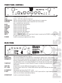
OFFICIAL WARWICK
AMP OWNER MANUAL
OFFICIAL WARWICK AMP OWNER MANUAL FOR
PROFET 3.3 AND PROFET 5.2
INDEX
Languages
English
05
Suffix
Technical Data and Schematic Diagram
65
ENGLISH
5
SAFETY HINTS
- Read these instructions
- Keep these instructions
- Heed all warnings
- Follow these instructions
Caution: To reduce the risk of electric shock, do
not open the amplifier’s case. Avoid exposure to
rain or moisture. No user serviceable parts inside, refer all service to a qualified technician. No
vessel filled with liquids, such as vases shall be
placed on top of the unit.
ENGLISH
This symbol, wherever it appears, alerts you to
the presence of dangerous non-insulated voltage
inside the case. Risk of electric shock!
6
This symbol, wherever it appears, indicates to
important operating and maintenance instructions in this user manual. Please read the manual.
!
This recycling logo informs the end user that it is
forbidden to throw away the product in the trash.
It has to be disposed of accordingly.
Weee-Nr.: DE93670540
CB Approved
Congratulations on the purchase of the new Warwick amplifier head/combo. Please read through these
instructions before connecting and operating the device. If you keep to the guidelines set out in this
manual, you will soon be able to appreciate the quality of this new Warwick amplifier. Please keep this
instruction booklet handy in case you need to consult it again. Please send the PASSPORT to the address
indicated therein.
RECOMMENDATIONS
The following recommendations are designed to ensure that the device always functions reliably:
• Never open the casing! To do so would expose you to the risk of an electric shock. Should repairs prove necessary, leave
them to qualified service personnel.
• Avoid dust and high moisture levels, direct sunlight and extremely high or low temperature.
• Safeguard the device from excessive vibration. Always place the unit on a stable and horizontal surface.
• See to adequate ventilation. The device should not be placed on soft surfaces (carpet, cushions, etc.). When mounting
it in a rack, make sure that the rear and lateral cooling vents remain unobstructed.
• Avoid leaving the unit near radiators or other objects producing heat.
• Internal components should only be adjusted or cleaned by qualified service technicians. Ensure no object or liquid
penetrates the device through its cooling vents.
• When replacing a fuse make sure you fit in one of identical value!
Have the device examined by a qualified service technician in the following cases:
• the mains lead or mains switch have been damaged,
• objects or liquids have penetrated the device,
• it has been exposed to excessive moisture,
• malfunctions or abnormal operating conditions have occurred,
• the device has been dropped or the casing damaged.
ENGLISH
HINTS
- This apparatus shall not be exposed dripping or splashing and that no objects filled with liquids, such as vases, shall
be placed on the apparatus.
- This apparatus should be connected to a MAINS socket outlet with a protective earthing connection.
- Mains plug or appliance connector shall be used as the disconnect device, so mains plug or appliance connector should
always remain readily operable.
- If the apparatus shows any malfunction, immediately disconnect the main power cord from the mains socket.
- Do only operate effects pedals in-between the instrument and the amplifier, as these devices are not designed for the
supplied load of an effects loop.
- Remove the plug whenever changing a fuse.
- Only ever replace a fuse with another of the same type. Never bridge defective fuses.
- Make sure the top and bottom of the device are properly ventilated and that the vents are not blocked.
- Do not subject the device to excessive vibration or hard jolts as these could damage the device.
- Don't undertake repairs yourself.
- Only allow the case to be opened by qualified personnel. (Remove the plug).
- Repairs should only be undertaken by qualified personnel.
SHOULD YOU FIND YOURSELF ONE DAY WONDERING: "WHY IS THERE NO SOUND COMING OUT?"
please check:
- all stub cables,
- all connections of these cables
and proceed anew by following the guidelines of the chapter GETTING STARTED. Possibly the problem reveals to be an
operational error.
7
PROTECTIVE CIRCUITS
Your new Warwick amplifier is equipped with a series of circuits to prevent it from destruction in case of inadequate operating conditions:
Power-up delay:
When the unit is switched on, the SPEAKER OUT sockets are activated with a slight delay to
protect the loudspeakers.
Short-circuit:
In the event of a short-circuit at the power amp outputs, this feature prevents the output stage
transistors from destruction by quickly reducing current.
Direct current (DC): This circuit continuously monitors the power amp output for direct current and protects the loud
speakers from overload should a transistor burn out.
HF oscillation:
Excessive
temperatures:
ENGLSIH
Note:
By switching the power amp off, this safety feature prevents from damages that could be caused
by frequencies in excess of 20 kHz (feedback, etc.).
Should the temperature-regulated fan cooler prove to be insufficient in extreme conditions, this
circuit protects the output stage transistors from destruction by switching the device off.
Note: You can recognise that one of these circuits has been activated as a result of a fault, when
the MUTE LED glows continuously even though you have not selected the MUTE mode. In case
of a shortcircuit please check the speaker cable. The amplifier must then be switched off and on
again, to get back into playing mode after having removed the short-circuit. In any other situati
on the amplifier switches automaticallyback to playing mode as soon as it detects the fault has
disappeared (e.g. the amplifier has overheated and cooled down again).
GETTING STARTED
1. Make sure that loudspeakers capable of sustaining the load of a bass signal are connected to the SPEAKER OUT
sockets (the speaker cables should meet a cross-section of at least 2 x 1.5 mm).
2. Check that the mains supply has been plugged in and that all external (effects) units possibly used are correctly connected and operational.
3. Set the MASTER control to zero.
4. Plug your bass guitar into the amplifier's INPUT with a shielded line-cable.
5. Press the POWER switch to turn the device on.
6. Switch MUTE off and the red LED will extinguish.
7. Switch the COMPRESSOR off (the 2-coloured LED will extinguish).
8. Turn all volume controls of your bass guitar on to their maximum.
9. Adjust the GAIN control until the (loudly) played bass signal flashes the Clip LED.
10. Set the MASTER control to the volume you wish to play at.
11. Adjust the sound that you wish with the controls and switches described in the respective chapters FRONT PANEL
CONTROLS.
12. If necessary readjust GAIN.
8
FRONT PANEL CONTROLS
BASS
LOW MID
HIGH MID
TREBLE
DEEP
BRIGHT
MASTER
MUTE
PHONES
Socket to plug in a bass guitar.
Control + CLIP LED to adjust the input level.
Switch to activate the compressor control to adjust the level of compression.
Switch to activate the contour control to adjust the level of the contour
(bass- and treble boost and mid cut)
Control to boost/cut deep frequencies.
Control to boost/cut low mids.
Control to boost/cut high mids.
Control to boost/cut high frequencies.
Control to boost/cut high mids.
Control to boost/cut high frequencies.
Control determines the mains level.
Switch + ON/MUTE LED cuts the signal from all outputs, except from the PHONES socket and leads
the signal to the TUNER OUT socket.
Socket for connecting a headphone (min 200 Ω).
REAR PANEL
POWER
MAINS IN AC
GROUNDLIFT
TUNER OUT
LINE OUT
EFF. LOOP
DI PRE/POST
DI OUT
SPEAKER OUT
PROFET 5.2
INPUT
GAIN
COMPRESSOR
CONTOUR
Switch for turning the amplifier on and off.
Terminal with integrated fuse compartment for connecting the amplifier to the current network.
Switch isolates the earth connection from the ground of the signal. Should several devices be simul
taneously connected to earth by the same conductor as well as via line connections, a so called hum
loop might appear. In this case operate GROUND LIFT to eliminate the current hum (when pressed).
Socket for the connection of a tuner. When MUTE mode is activated, the unmodified bass signal is
retained here.
Socket allows to connect additional power amplifiers or active cabinets.
For the insertion of effects units. Connect SEND with the input and RETURN with the output of the
effects device.
Switches the signal lying at the DI OUT socket.
Socket, PRE (pressed) unmodified bass signal, or POST (unpressed) bass signal treated by the tone
controls ans possibly by connected effect devices.
Socket for connecting the loudspeaker.
9
FRONT PANEL CONTROLS
INPUT
GAIN
COMPRESSOR
CONTOUR
PROFET 3.3
BASS
LOW MID
HIGH MID
TREBLE
DEEP
BRIGHT
MASTER
MUTE
PHONES
Socket to plug in a bass guitar.
Control + CLIP LED to adjust the input level.
Switch to activate the compressor control to adjust the level of compression.
Switch to activate the contour control to adjust the level of the contour
(bass- and treble boost and mid cut)
Control to boost/cut deep frequencies.
Control to boost/cut low mids.
Control to boost/cut high mids.
Control to boost/cut high frequencies.
Control to boost/cut high mids.
Control to boost/cut high frequencies.
Control determines the mains level.
Switch + ON/MUTE LED cuts the signal from all outputs, except from the PHONES socket and leads
the signal to the TUNER OUT socket.
Socket for connecting a headphone (min 200 Ω).
REAR PANEL
POWER
MAINS IN AC
GROUNDLIFT
TUNER OUT
LINE OUT
EFF. LOOP
DI PRE/POST
DI OUT
SPEAKER OUT
10
Switch for turning the amplifier on and off.
Terminal with integrated fuse compartment for connecting the amplifier to the current network.
Switch isolates the earth connection from the ground of the signal. Should several devices be simul
taneously connected to earth by the same conductor as well as via line connections, a so called hum
loop might appear. In this case operate GROUND LIFT to eliminate the current hum (when pressed).
Socket for the connection of a tuner. When MUTE mode is activated, the unmodified bass signal is
retained here.
Socket allows to connect additional power amplifiers or active cabinets.
For the insertion of effects units. Connect SEND with the input and RETURN with the output of the
effects device.
Switches the signal lying at the DI OUT socket.
Socket, PRE (pressed) unmodified bass signal, or POST (unpressed) bass signal treated by the tone
controls ans possibly by connected effect devices.
Socket for connecting the loudspeaker.
TECHNICAL DATA - PROFET 3.3 / 5.2
Input
25 mV
Preamp
transistor, active controlled
Poweramp
fan cooled (non permanent)
Equalizer
Bass
Low Mid
Hi Mid
Treble
±12dB @ 80Hz
±12dB @ 200Hz
±12dB @ 600Hz
±14dB @ 5kHz
Deep
Bright
+12dB @ 30Hz
+8dB @ 3kHz
+14dB@ 16kHz
Contour
+20dB @ 20Hz
-10dB @ 300Hz
+12dB @ 10kHz
Compressor
adjustable
Headphone
200 ohms min.
Direct Out
0dB, 600 ohms
mono serial
send 0dB, 600 ohms
return 0dB, 10k ohms
Groundlift, DI pre/post
jack and lockable coaxial
300W/4 ohms (Profet 3.3)
500W/4 ohms (Profet 5.2)
< 0.1 %
Effects Loop
Switches
Speaker Out
THD
Weight
8.5 kg (Profet 3.3)
10.0 kg (Profet 5.2)
Dimensions
19" / 483 x 90 x 350 (w*h*d)
17
DIAGRAM - PROFET 3.3 / 5.2
CONNECT SPEAKERS - PROFET 3.3 / 5.2
Note: The minimum load of the power amplifier is 4 ohms.
Speaker Set-up
Quantity
4
16 ohms Cabinets
2
8 ohms Cabinets
1
6 ohms Cabinet
1
4 ohms Cabinet
ProFet
Cabinet WCA 211 Pro
(8 ohms)
Cabinet WCA 115 Pro
(8 ohms)
66
67
Please see the new Warwick Bass Forum on www.warwick.de
For support information please refer to [email protected]
Visite por favor el nuevo forum Warwick de bajo en www.warwick.de
Para soporte técnico e información, dirigirse por favor a [email protected]
Por favor veja o novo Fórum de Baixos da Warwick em HYPERLINK www.warwick.de
Para mais informações escreva para HYPERLINK [email protected]
Visitare il nuovo Forum Warwick Bass: www.warwick.de
Per supporto tecnico: [email protected]
Veuillez consulter le nouveau forum sur les basses Warwick à l'adresse www.warwick.de
Si vous avez besoin de plus d'informations contactez [email protected]
Das neue Warwick Bass Forum finden Sie auf www.warwick.de
Bei technischen Fragen wenden Sie sich bitte an [email protected]
Nové Warwick Bass Forum najdete na webov˘ch stránkách: HYPERLINK "http://www.warwick.de
Máte-li nûjaké technické dotazy, pi‰te na: [email protected]
Headquarters:
Branch China:
Branch UK:
Branch Switzerland:
Branch CZ/SK:
Branch PL:
Warwick GmbH&Co.Music Equipment KG • Gewerbepark 46 • 08258 Markneukirchen/Germany • E-Mail: [email protected]
Warwick Music Equipment (Shanghai) Ltd., Co.• Shanghai Waigaoqiao Free Trade Zone • Shanghai 200131/P.R.China • E-Mail: [email protected]
Warwick Music Equipment Trading (Manchester UK) Ltd. • 75 Bridge Street • Manchester M3 2RH / Great Britain • E-Mail: [email protected]
Warwick Music Equipment Trading (Zurich) GmbH • Kriesbachstrasse 30 • 8600 Dübendorf / Switzerland • E-Mail: [email protected]
Warwick Music Equipment Trading (Praha CZ) s.r.o. • Spálená 23/93 • 11000 Praha 1 / Czech Republic • E-Mail: [email protected] z
Warwick Music Equipment Trading (Warsaw) Sp. z o.o. • Flory 7/18a • 00-586 Warsaw / Poland • E-Mail: [email protected]
Visit us on the World Wide Web: www.warwick.de • www.warwick-distribution.de & join the WARWICK BASS FORUM: www.warwick.de/forum