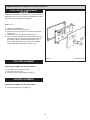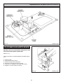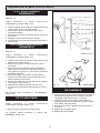
1
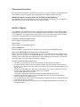
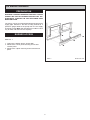
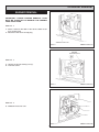
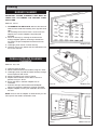
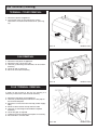
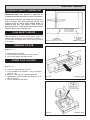
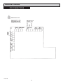
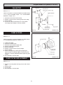
Servicing
Instructions
XT - Oil (K/PF)
For use in GB and IE
DESN 514112 B
Remember, when replacing a part on this appliance, use only spare parts that you can be assured conform the safety and
performance specification that we require. Do not use reconditioned or copy parts that have not been clearly authorised
by AGA.
PLEASE READ THESE INSTRUCTIONS BEFORE SERVICING THIS APPLIANCE
[email protected]
10/13 EINS 514138
Contents
SECTION
CONTENTS
PAGE
CONSUMER PROTECTION
HEALTH & SAFETY
3
3
INTRODUCTION
SERVICE SCHEDULE
4
4
OIL BURNER REMOVAL
PREPARATION
BURNER ACCESS
BURNER REMOVAL
5
5
6
CLEANING
BURNER CHAMBER
OVEN & HOTPLATE FLUEWAY CLEANING
7
7
OIL BURNER SERVICING
BURNER NOZZLE REMOVAL
IGNITION ELECTRODE
PHOTO ELECTRIC CELL (PEC) CLEANING
FAN CLEANING
OIL LINE FILTER CLEANING
FLEXIBLE OIL LINES
8
8
9
9 - 10
10
10
RE-COMMISSIONING - OIL
BLEED AIR FROM OIL SUPPLY
FIT PRESSURE PAUGE
SWITCH ON ELECTRICITY
VENT OIL PUMP
ADJUST OIL PRESSURE
SET COMBUSTION AIR
CHECK SMOKE
11
11
11
11
11
12
12
FAN TERMINAL (CLEANING)
TERMINAL COVER REMOVAL
FAN REMOVAL
FLUE TERMINAL REMOVAL
13
13
13
ELECTRICAL CONTROLS
OVERHEAT SAFETY THERMOSTAT
FLUE SAFETY DEVICE
REMOVAL OF PCB
POWER FLUE CONTROL
PCB CONNECTIONS
14
14
14
14
15
REPLACEMENT OF PARTS (BURNER) FAN MOTOR
PUMP ACCESS
PUMP FILTER REPLACEMENT
SOLENOID COIL
IGNITION TRANSFORMER
IGNITION ELECTRODES
CONTROL BOX
PEC
16
16
16
17
17
17
18
18
REPLACEMENT OF PARTS
(ELECTRICAL CONTROLS)
ELECTRICAL COMPONENT ACCESS
PCB REPLACEMENT
FAN REPLACEMENT
TO FIT NEW FLUE SAFETY DEVICE
TO FIT NEW OVERHEAT THERMOSTAT
TO FIT NEW OVEN CONTROL THERMOSTAT
TO FIT NEW TIMER
RE-ASSEMBLE ELECTRICAL ASSEMBLY
19
19
19
20
21
21
21
21
ELECTRICAL CONTROLS
WIRING DIAGRAM - APPLIANCE
WIRING DIAGRAM - BURNER ONLY
FAULT-FINDING BURNER
HIGH SMOKE NUMBERS & OIL SMELLS
FAULT FINDING CHART - GENERAL 400K P/F
FAULT FINDING CHART - BURNER
FAULT FINDING CHART - CONTROLS
22
23
24
25
26
27
28 - 29
2
Consumer Protection
As responsible manufacturers we take care to make sure that are products are designed and
constructed to meet the required safety standards when properly installed and used.
IMPORTANT NOTICE: PLEASE READ THE ACCOMPANYING WARRANTY
Any alteration that is not approved by AGA could invalidate the approval of the appliance,
operation of the warranty and could affect your statutory rights.
Health & Safety
This appliance may contain some of the materials that are indicated It is the Users/Installers
responsibility to ensure that the necessary personal protective clothing is worn when handling
where applicable, the pertinent parts that contain any of the listed materials that could be
interpreted as being injurious to health and safety, see below for information.
Firebricks, Fuel beds, Artificial Fuels
When handling use disposable gloves.
Fire cement
When handling use disposable gloves.
Glues and Sealants
Exercise caution - if these are still in liquid form use face mask and disposable gloves.
Glass Yarn, Mineral Wool, Insulation Pads, Ceramic Fibre
May be harmful if inhaled. May be irritating to skin, eyes, nose and throat. When handling avoid
contact with skin or eyes. Use disposable gloves, face-masks and eye protection. After
handling wash hands and other exposed parts. When disposing of the product, reduce dust
with water spray, ensure that parts are securely wrapped.
Kerosene & Gas Oil fuels (mineral oils)
1. The effect of mineral oils on the skin vary according to the duration of exposure.
2. The lighter fractions also remove the protective grease normally present on the surface of
the skin. This renders the skin dry, liable to crack and more prone to damage caused by cuts
and abrasions.
3. ‘Oil acne’ is recognised by the presence of skin rashes. The arms are most often affected,
but may occur where there is contact with oil or oily clothing.
- Seek medical attention for any rash.
- Avoid skin contact with mineral oil or clothing contaminated with mineral oil.
4. Inhalation of mineral oil vapours must be avoided. Never fire the burner in the open as
unburnt oil vapours are likely to occur.
5. Use a suitable barrier cream which will give protection against mineral oil, lanolin based hand
creams are usually very effective.
6. Never syphon mineral oils by use of the mouth. If accidentally swallowed, call a doctor, do
not induce vomiting.
3
INTRODUCTION
SERVICE SCHEDULE
To ensure the best performance from your Rayburn it
should be serviced once a year.
Annual Service
BURNER REMOVAL - for cleaning and inspection.
CLEANING - Heat exchanger flueways, oven and
hotplate flueways together with ceramic fibre burner
chambers.
BURNER SERVICING.
OIL PUMP SERVICING - Cleaning of fuel line strainer.
RE-COMMISSIONING.
REPLACEMENT PARTS.
This appliance must be commissioned by a competent
engineer, such as OFTEC approved.
Failure to install and maintain appliances correctly could
lead to prosecution.
An additional flueway and combustion chamber clean
halfway through the season may be necessary in some
cases.
NOTE: The external extractor fan should be regarded as
a consumable part and replaced every 2 years.
The Rayburn cannot be serviced whilst hot, so the
thermostat should be turned off on the evening before the
service visit.
Oven Door Fit - Both doors must be checked and
adjusted if necessary to ensure the alignment with the
door catch is correct, the keep is secure and the oven is
sealed when the door is closed.
IMPORTANT: FLEXIBLE OIL LINE MUST BE
RENEWED AT EACH SERVICE ON A 12 MONTHLY
BASIS.
4
Oil Burner Removal
PREPARATION
WARNING: BEFORE REMOVING SERVICE ACCESS
COVERS OR THE OIL BURNER ENSURE THAT ALL
ELECTRICAL SUPPLIES TO THE APPLIANCE HAVE
BEEN ISOLATED.
The burner can be removed without disconnecting the oil
supply pipe. However if the filter is being cleaned or a
pressure gauge fitted to the pump then the oil supply
should be turned OFF and arrangements made to catch
any oil which will leak from the oil pump.
BURNER ACCESS
SEE FIG. 1
1. Open up the bottom burner access door.
2. Remove the 4 inner panel securing screws and
remove panel.
3. Remove the 3 plinth securing screws and remove
plinth.
FIG. 1
5
DESN 514110 B
Oil Burner Removal
BURNER REMOVAL
IMPORTANT: DURING BURNER REMOVAL CARE
MUST BE TAKEN NOT TO DAMAGE THE CERAMIC
FIBRE INSULATION.
SEE FIG. 2
1. Place a sheet on the floor in front of the cooker to act
as a working area
2. Disconnect the terminal strip plug.
FIG. 2
DESN 511431 A
BURNER
LOCKING BOLTS
SEE FIG. 3
3. Loosen the burner locking nuts (2).
4. Twist the burner.
FIG. 3
DESN 511432 A
FIG. 4
DESN 511433 B
SEE FIG. 4
5. Withdraw the burner unit.
6
Cleaning
BURNER CHAMBER
IMPORTANT: DURING CLEANING CARE MUST BE
TAKEN NOT TO DAMAGE THE CERAMIC FIBRE
INSULATION.
SEE FIG. 5 & 5A
1. TO REMOVE THE HOTPLATE: Remove the bolt and
washers from inside the Roasting Oven (top left hand
side)
Lift insulating covers and remove 2 screws from the
hotplate, then remove hotplate using lifting tool
provided.
2. Clean the flueway by inserting the flexible brush
through top plate aperture, directing it towards the
flue outlet. Scrape the deposits towards the burner
chamber.
3. Thoroughly clean burner chamber flueway
4. Carefully vacuum any debris that has fallen down into
the burner chamber.
FIG. 5
DESN 514184
FIG. 5A
DESN 514113
OVEN & HOTPLATE FLUEWAY
CLEANING
SEE FIG. 5A, 5 & 6
1. Open the top oven door.
2. Remove side and base access doors using hex. driver.
3. Thoroughly clean, top side and base flueways through
access apertures with brush.
4. Remove all debris with vacuum cleaner.
5. Replace side and base access doors. Secure in
position using hex. driver.
6. Brush and clean in between hotplate ribs on
underside.
7. Examine soft rope seal located around hotplate
aperture in top plate. Replace if frayed or damaged.
8. Replace hotplate ensuring the underside ribs lie over
the oven.
NOTE: Ensure that the hotplate is fitted correctly as this
forms part of the cooker combustion circuit.
FIG. 6
7
DESN 514118 A
Oil Burner Servicing
BURNER NOZZLE REMOVAL
SLACKEN (2) HEX.
SCREWS
SEE FIG. 7
CHANGE THE NOZZLE AT THE ANNUAL SERVICE.
1.
Remove blast tube by slackening two hex. screws.
Thoroughly clean the blast tube.
2. Remove (2) screws securing access door.
3. Slacken (2) screws on either side of access door.
4. Open access door.
5. Remove push on electrode leads.
6. Slacken screws securing electrodes.
7. Pull out electrodes.
8. Using socket spanner unscrew nozzle. Ensuring
hexagon is held, to stop nozzle holder turning.
9. Remove nozzle and check filter for debris. Replace
with one of same specified make and pattern
10. Refit nozzle taking care not to overtighten.
11. Re-assemble in reverse order.
DESN 511436 A
NOTE: Do not touch the face of nozzle to avoid blocking
of fine drilling.
IGNITION ELECTRODE
SEE FIG. 7 and PAGE 15.
Inspect the ignition electrodes for crazing in the porcelain.
Replace if there are any signs of deterioration.
DESN 511437
FIG. 7
8
DESN 510238
Oil Burner Servicing
PHOTO ELECTRIC CELL (PEC)
CLEANING
SEE FIG. 8
Withdraw Photo Electric Cell from the burner head.
Clean PEC sensing end with a soft cloth taking care not
to scratch the light sensitive body. Re-insert the PEC
taking care to insert the correct way round.
IF BADLY DISCOLOURED CHANGE IT.
FIG. 8
DESN 511438
FAN CLEANING
SEE FIG. 9
INSPECT AND CLEAN IF NECESSARY.
1. Remove (2) screws securing terminal strip/
transformer bracket.
2. Remove (2) push on electrode leads from transformer.
DESN 511439
FIG. 9
9
DESN 511440
Oil Burner Servicing
SEE FIG. 10
3. Remove (3) screws securing fan motor onto burner
body.
4. Withdraw assembly from burner body.
5. Clean impeller with a soft brush.
6. Spin motor to check that it turns easily.
FIG. 10
DESN 511441
FIG. 11
DESN 511442
SEE FIG. 11
7. Remove (1) screw and slacken (2) screws from air
slider control.
8. Remove air slider and clean any fluff deposits.
9. Re-assemble in reverse order ensuring that earth
terminal is secured behind the screw onto the
terminal/transformer bracket.
OIL LINE FILTER CLEANING
1. Turn OFF the line isolating valve fitted prior to the oil
line filter.
2. Dismantle filter by unscrewing bolt at base of bowl.
3. Make arrangements to catch kerosene.
4. Wash filter thoroughly in clean kerosene.
5. Re-assemble filter in reverse order of removal.
FLEXIBLE OIL LINES
REMEMBER
Do not kink hoses.
Do not pass hoses through side casing panels.
Always flush oil through before final connection.
Check hose for signs of discolouration, cracking or oil
seepage. Replace if necessary.
10
Re-commissioning - Oil
BLEED AIR FROM OIL SUPPLY
Disconnect the flexible oil pipe at the pump inlet, open the
stop valve slowly and run off some of the oil into a
receptacle to establish an air free supply to the pump.
Remake the connection oil tight and leave valve open.
FIT PRESSURE GAUGE
SEE FIG. 12
Remove the bleed screw from the manifold and fit an oil
pressure gauge with R1/8 connection to check the pump
output pressure.
SWITCH ON ELECTRICITY
Set the thermostat to maximum. The burner should run on
pre-purge for 7 to 15 seconds, with the ignition spark
energised. The oil solenoid valve should open allowing
the burner to fire.
Until all the air from the oil pump is flushed out there may
be some flame instability resulting in the burner locking
out. This will be shown by the burner stopping and the
illumination of the signal light in the reset button of the
control box (see Fig. 13). IN THIS EVENT, WAIT AT
LEAST ONE MINUTE, then press the re-set button to
restart.
FIG. 12
DESN 511427
FIG. 13
DESN 511428
VENT OIL PUMP
SEE FIG. 12
Whilst the burner is running, vent air from the pump by
slackening the pressure gauge port sufficient to allow air
to bleed out. When bubble free oil seeps out re-tighten.
ADJUST OIL PRESSURE
SEE FIG. 12
With the burner running check the oil pressure on the
pressure gauge.
If the pressure gauge is not indicating the correct reading
then adjust the pressure by turning the pressure regulator
clockwise to increase or anti-clockwise to decrease the
pressure until the pressure gauge reads 7.6 bar (110
lb/in2).
11
Re-commissioning - Oil
SET COMBUSTION AIR
SEE FIG. 14
After 15 minutes of the burner running.
To sample the flue gases from the cooker burner lift up
the R.H. insulating cover and remove the countersunk
headed screw and insert the sensing end of a portable
analyser to check the CO2 (Carbon Dioxide) level in the
hotplate. The cooker burner should be set to 11.0% CO2.
IMPORTANT:
Ensure that the bottom louvered plinth is in place during
combustion setting procedures and the outer door is
closed.
CHECK SMOKE
Remove the CO2 sampling tube and using the same hole
for flue sampling insert the sensing end of a Baccarach
Smoke Pump and check that the smoke in the flue ways
does not exceed 0-1 on the scale.
DESN 511429 A
Replace the countersunk headed screw on completion
ensuring that it will not interfere with any pots and pans
placed on the hotplate.
FIG. 14
12
DESN 514111
Fan Terminal (Cleaning)
TERMINAL COVER REMOVAL
1. Disconnect power to appliance.
2. The terminal cover is secured using 4 screws.
Unscrew the 4 screws and remove cover. (See Fig.
15).
FIG. 15
DESN 513351
FIG. 16
DESN 513355
FIG. 16A
DESN 513354
FAN REMOVAL
1. Disconnect the power to appliance.
2. Disconnect the 3 wires to the fan.
3. Unscrew (3) M5 fixings and withdraw, fan and mount
assembly.
4. Clean fan with a soft brush.
5. Re-fit fan and mount assembly.
FLUE TERMINAL REMOVAL
In order to gain access to the flue for cleaning it is
necessary to remove the flue terminal assembly.
1. Disconnect the power to the appliance.
2. Unscrew (4) M5 fixings that connect the flue pipe to
the terminal backplate.
3. Disconnect 3 wires from terminal strip (cooker supply
side).
4. Remove cable restraint clamp and free cable.
5. Unscrew (4) wall fixings and withdraw backplate
assembly.
6. Clean flue pipe as required.
7. Inspect flue terminal gasket and replace if necessary.
8. Re-assemble in reverse order.
13
Electrical Controls
OVERHEAT SAFETY THERMOSTAT
IMPORTANT NOTE: This appliance is fitted with an
overheat thermostat which has a manual reset button.
If the overheat stat trips, the cooker will not operate,
until the button has been pushed-in (reset). The
engineer needs to follow ‘Fault Finding Guide’ to
establish why the stat tripped. (The overheat
thermostat and its sensing phial are located on the
controls chassis rear). (See Fig. 25).
FLUE SAFETY DEVICE
This thermostat is a safety cut-out device which will
operate under adverse wind or a blocked flue condition. It
is a manually reset device which can be reset by pressing
in the centre.
FIG. 17
DESN 514123 B
FIG. 18
DESN 512570
FIG. 19
DESN 512562
REMOVAL OF PCB
SEE FIG. 18
1. Remove plinth (3 screws).
2. Unscrew two fixing screws just in front of PCB.
3. Lift the PCB slightly and slide forward.
POWER FLUE CONTROL
SEE FIG. 19
1. Check the control voltage to the fan.
2. Turn the appliance on. Between + and - the voltage
will be 24V dc.
3. Between - and signal the voltage should read
approximately 4.0V dc initially, then drop to 2.6V dc
after 30 seconds.
4. The fan should also slow down.
14
Electrical Controls
PCB CONNECTIONS
FIG. 20
15
Replacement of parts (Oil Burner)
FAN MOTOR
SEE FIG. 21
Follow instructions in sections BURNER ACCESS, Steps
1 to 3, FAN CLEANING, Steps 1 to 4 and BURNER
REMOVAL, Steps 1 to 5.
1.
2.
3.
4.
Disconnect wires from terminal strip.
Slacken (3) grub screws securing pump to fan body.
Remove pump.
Fit new fan motor and assemble in reverse order
ensuring pump coupling is correctly located.
FIG. 21
DESN 511447
FIG. 22
DESN 511448
PUMP ACCESS
SEE FIG. 21
Follow instructions in section BURNER ACCESS, Steps 1
to 3 and BURNER REMOVAL, Steps 1 to 5.
1.
2.
3.
4.
5.
6.
7.
8.
Isolate fuel supply.
Disconnect flexible hose.
Disconnect pump outlet supply tube.
Remove solenoid securing nut.
Remove solenoid.
Slacken (3) grub screws on pump flange.
Remove pump.
When re-fitting pump, inspect pump coupling for
signs of wear or cracking, replace if necessary and
ensure it is correctly positioned before tightening grub
screws.
9. Re-assemble in reverse order.
PUMP FILTER REPLACEMENT
SEE FIG. 22
1. Remove (4) pump plate securing screws and remove
plate.
2. Remove filter.
3. Fit new filter.
4. Re-assemble in reverse order.
16
Replacement of parts
(Oil Burner)
SOLENOID COIL
SEE FIG. 21
Follow instructions in sections BURNER ACCESS, Steps
1 to 3 and BURNER REMOVAL, Steps 1 to 5.
1.
2.
3.
4.
Remove solenoid plug securing nut.
Pull off electrical connection socket from solenoid.
Remove solenoid coil.
Fit new solenoid coil, re-assemble in reverse order.
IGNITION TRANSFORMER
Follow instructions in sections BURNER ACCESS, Steps
1 to 3.
1.
2.
3.
4.
5.
Remove (4) screws securing transformer.
Remove both H.T. leads from transformer.
Disconnect the wires from the terminal strip.
Remove transformer.
Fit new transformer, re-assemble in reverse order.
IGNITION ELECTRODES
SEE FIG. 7
Follow instructions in sections BURNER ACCESS, Steps
1 to 3, BURNER REMOVAL, Steps 1 to 5 and BURNER
NOZZLE REMOVAL, Steps 2 to 7.
1. Remove ignition electrode assembly.
2. Fit new ignition electrode assembly, in reverse order
of removal.
3. Check electrode gap and rest if necessary.
17
Replacement of parts
(Oil Burner)
CONTROL BOX
SEE FIG. 23
Follow instructions in sections ‘BURNER ACCESS’,
Steps 1 to 3.
1. Insert flat bladed screwdriver in LH side of c.box, as
diagram.
2. Repeat as above for RH side.
3. Gently pull control box away from mounting plate.
4. Fit new control box, re-assemble in reverse order.
FIG. 23
PEC
SEE FIG. 8
Follow instructions in sections BURNER ACCESS, Steps
1 to 3, BURNER REMOVAL, Steps 1 to 5.
1.
2.
3.
4.
5.
6.
Unplug PEC.
Undo wire connections from terminal strip.
Withdraw PEC cable.
Slacken and remove PEC clip (note orientation of clip).
Transfer and secure clip to new PEC.
Fit new PEC, re-assemble in reverse order.
18
DESN 511249
Replacement of parts
(Electrical controls)
ELECTRICAL COMPONENT
ACCESS
BEFORE REMOVING SERVICE ACCESS COVERS
ENSURE THAT ALL ELECTRICAL SUPPLIES TO THE
APPLIANCE HAVE BEEN TURNED OFF.
SEE FIG. 24
1. Open the controls door.
2. Remove thermostat control knob.
3. Remove 2 cover panel securing screws and remove
cover panel.
4. Remove the four control panel fixing screws.
5. Tilt the chassis forwards from the top and lift out. To
fully access the rear of the control chassis, the oven
thermostat capillary should be removed from the
oven. Follow instructions in section ‘TO FIT NEW
OVEN CONTROL’ thermostat, Steps 3 to 6.
FIG. 24
PCB REPLACEMENT
SWITCH OFF POWER TO THE APPLIANCE.
1. See Page 11 for removal of PCB.
2. Disconnect all the wires.
3. Fit wires to new PCB (wiring on Page 22).
FAN REPLACEMENT
SWITCH OFF POWER TO THE APPLIANCE.
1. Access and Removal, see Page 12.
19
DESN 514121
Replacement of parts (Electrical controls)
FIG. 25
DESN 516745
TO FIT NEW FLUE SAFETY DEVICE
ENSURE THAT ALL ELECTRICAL SUPPLIES TO THE
APPLIANCE HAVE BEEN TURNED OFF.
SEE FIG. 26
Follow instructions in section BURNER ACCESS, Steps 1
to 3.
1.
2.
3.
4.
5.
6.
Remove PCB.
Unscrew flue safety device.
Remove bracket and unclip phial.
Disconnect the two wires on the switch.
Unscrew nut holding the stat body and remove.
Replace in reverse order of removal.
FIG. 26
20
DESN 512569
Replacement of parts (Electrical controls)
TO FIT NEW OVERHEAT
THERMOSTAT
SEE FIG. 25
Follow
instructions
in
section
COMPONENT ACCESS, Steps 1 to 5.
ELECTRICAL
1. Undo the locknut, which holds the overheat thermostat
to the bracket on the rear of the chassis.
2. Remove the 2 push on connectors from back of
overheat thermostat.
3. Remove the phial from the 2 spring clips on the rear of
the chassis.
4. Withdraw overheat thermostat from chassis.
5. Fit replacement overheat thermostat and assemble in
reverse order.
COOKER
THERMOSTAT
TO FIT NEW OVEN CONTROL
THERMOSTAT
THERMOSTAT
PHIAL LOCATION
SEE FIG. 27
Follow
instructions
in
section
COMPONENT ACCESS, Steps 1 to 5.
DESN 511738 C
ELECTRICAL
1. Undo the two screws on the front of the chassis which
holds the thermostat in place.
2. Remove the (2) push on connectors from back of
thermostat.
3. Open roasting oven door and using a screwdriver,
loosen the rear fixing screws and remove the front
fixing screw of the inner L.H. oven side to expose the
thermostat stat phial.
4. Slacken the single screw where the phial passes
through the roasting oven side and rotate the cover
plate to open the access hole.
5. Slacken the single screw on the phial securing bracket
and rotate the cover bracket.
6. Withdraw the capillary and phial from the oven.
7. Fit replacement thermostat and assemble in reverse
order.
ORANGE
FIG. 27
RE-ASSEMBLE
To complete, follow instructions in ‘RE-ASSEMBLE’,
Steps 1 to 5.
1. Locate the base of the control chassis into the bottom
of the doorway aperture, tilt the chassis backwards
into position and secure with the (4) screws.
2. Thread the wires for the cooker timer through the
aperture and connect them onto the rear of the cooker
timer fitted in the outer panel.
3. Refix the outer panel in position and secure with the
(2) screws.
4. Replace the thermostat knob.
5. Replace the controls door.
TO FIT NEW TIMER
Follow
instructions
in
section
COMPONENT ACCESS’ Steps 1 to 4.
DESN 510546
‘ELECTRICAL
1. Remove timer by depressing retaining clips.
To complete follow instructions in section ‘REASSEMBLE’, Steps 2 to 5.
21
Fault Finding
WIRING DIAGRAM - APPLIANCE
FIG. 28
22
Fault Finding
WIRING DIAGRAM - BURNER ONLY
FIG. 29
23
Fault Finding
Burner
Check that the burner has not gone to lockout.
Causes of lockout can be:l
l
l
l
l
l
l
l
No ignition, ignition electrode incorrectly positioned or insulation cracked, spark generator faulty, check for 230V
at spark generator.
No oil supply.
Poor combustion.
Photo electric cell incorrectly positioned, cracked or needs cleaning.
Live and Neutral connections reversed.
Oil valves not properly closed in shutdown position.
Faulty control box.
Faulty fire valve.
General
For access to individual controls refer to section on Replacement Parts and for wiring continuity checks refer to schematic
wiring layouts.
To check out the electrical wiring at the burner you will first have to have access to the burner chamber. Use the following
procedure:1.
2.
3.
4.
Isolate the electrical power supply.
Open up the bottom burner access door. Remove door and put in a safe place.
Unscrew the 4 screws holding the inner panel in place and remove panel.
Unscrew the 3 screws holding the louvered plinth in place and remove plinth.
The external mains connections are made to the controller in the front right hand corner of the cooker under the oven.
Re-connect the electrical supply and check that there is 230V power supply available across the mains input connections
L & N on the controller. If not then check connecting leads, fuse and whether power is available at mains plug.
If power is available across L & N check the appliance.
24
Fault Finding
HIGH SMOKE NUMBERS
NOZZLE FAULT
REPLACE
NOZZLE
AIR INTAKE
BLOCKED
CHECK AIR INLET
TO BURNER
INCORRECT
COMBUSTION
SETTINGS
RE-ADJUST
TO
INSTALLATION
INSTRUCTIONS
OIL PRESSURE
INCORRECT
ADJUST TO
RECOMMENDED
SETTINGS
INCORRECT
COMPONENTS
USED ON
COMBUSTION
HEAD
SEE SERVICING
INSTRUCTIONS
INTERNAL BURNER
CHAMBER
INSULATION
PANELS
INCORRECTLY
POSITIONED
OR
FAULTY
OIL SMELLS
FUMES ON
START UP
DOWN
DRAUGHT
CHECK WITH
GAUGE
OIL SOAKED
HEARTH
NUMEROUS
LOCK-OUTS
ODOURS
IN
KITCHEN
BURNER
FAULT
CURE THE
LOCK-OUT
CONDITION
25
OIL LEAKS AT
PIPE FITTINGS
TAKE APART
AND
REMAKE AS
REQUIRED
LEAKS AT
TUBING
CONNECTORS
ENSURE END
OF TUBING
SQUARE
Fault Finding
IMPORTANT NOTE: REFER TO OVERHEAT THERMOSTAT’, PAGE 14.
26
Fault Finding
27
Fault Finding
28
Fault Finding
29
30
31
For further advice or information contact
your local distributor/stockist
With AGA Rangemaster’s policy of continuous
product improvement, the Company reserves the
right to change specifications and make
modifications to the appliance described at any
time.
Manufactured by
AGA Rangemaster
Station Road
Ketley Telford
Shropshire TF1 5AQ
England
www.rayburn-web.co.uk
www.agacookshop.co.uk
32