1
BSC Programmer’s Guide
DC 900-1340I
Protogate, Inc.
12225 World Trade Drive, Suite R
San Diego, CA 92128
December 2002
Protogate, Inc.
12225 World Trade Drive, Suite R
San Diego, CA 92128
(858) 451-0865
BSC Programmer’s Guide
© 2002 Protogate, Inc. All rights reserved
Printed in the United States of America
This document can change without notice. Protogate, Inc. accepts no liability for any errors this
document might contain.
Freeway is a trademark of Protogate, Inc.
All other trademarks and trade names are the properties of their respective holders.
Cross References:
(keep this hidden)
BSC
bsc
Binary Synchronous
Communications
BSC 3270
BSC 2780/3780
Contents
List of Figures
11
List of Tables
13
Preface
17
1
25
Introduction
1.1
Product Overview . . . . . . . . . . . . . . . . . . .
1.1.1 Freeway Server . . . . . . . . . . . . . . . . . .
1.1.2 Embedded ICP . . . . . . . . . . . . . . . . . .
1.2 Freeway Client-Server Environment . . . . . . . . .
1.2.1 Establishing Freeway Server Internet Addresses
1.3 Embedded ICP Environment . . . . . . . . . . . . .
1.4 Client Operations . . . . . . . . . . . . . . . . . . .
1.4.1 Defining the DLI and TSI Configuration . . . .
1.4.2 Opening a Session . . . . . . . . . . . . . . . .
1.4.3 Exchanging Data with the Remote Application .
1.4.4 Closing a Session . . . . . . . . . . . . . . . . .
1.5 BSC Product Overview . . . . . . . . . . . . . . . .
1.5.1 Software Description . . . . . . . . . . . . . . .
1.5.2 Hardware Description . . . . . . . . . . . . . .
2
.
.
.
.
.
.
.
.
.
.
.
.
.
.
.
.
.
.
.
.
.
.
.
.
.
.
.
.
.
.
.
.
.
.
.
.
.
.
.
.
.
.
.
.
.
.
.
.
.
.
.
.
.
.
.
.
.
.
.
.
.
.
.
.
.
.
.
.
.
.
.
.
.
.
.
.
.
.
.
.
.
.
.
.
.
.
.
.
.
.
.
.
.
.
.
.
.
.
.
.
.
.
.
.
.
.
.
.
.
.
.
.
.
.
.
.
.
.
.
.
.
.
.
.
.
.
.
.
.
.
.
.
.
.
.
.
.
.
.
.
.
.
.
.
.
.
.
.
.
.
.
.
.
.
.
.
.
.
.
.
.
.
.
.
.
.
.
.
BSC Protocol Summary
2.1
BSC 3270 Protocol Implementation . .
2.1.1 3270 Control Station Operation . .
2.1.2 3270 Tributary Station Operation .
2.1.3 Transmission Codes . . . . . . . .
DC 900-1340I
25
25
27
29
30
30
30
30
31
31
31
31
32
32
33
.
.
.
.
.
.
.
.
.
.
.
.
.
.
.
.
.
.
.
.
.
.
.
.
.
.
.
.
.
.
.
.
.
.
.
.
.
.
.
.
.
.
.
.
.
.
.
.
.
.
.
.
.
.
.
.
.
.
.
.
.
.
.
.
.
.
.
.
.
.
.
.
.
.
.
.
33
34
34
34
3
BSC Programmer’s Guide
2.1.4 Messages and Transmission Blocks. .
2.1.5 BSC 3270 Product Features. . . . . .
2.2 BSC 3270 Access Modes . . . . . . . . . .
2.3 BSC 2780/3780 Protocol Implementation
2.3.1 BSC 2780 Protocol . . . . . . . . . .
2.3.2 BSC 3780 Protocol . . . . . . . . . .
2.3.3 Transmission Codes. . . . . . . . . .
2.3.4 Messages and Transmission Blocks. .
2.3.5 BSC 2780/3780 Product Features. . .
2.4 BSC 2780/3780 Access Modes . . . . . . .
3
.
.
.
.
.
.
.
.
.
.
.
.
.
.
.
.
.
.
.
.
.
.
.
.
.
.
.
.
.
.
.
.
.
.
.
.
.
.
.
.
.
.
.
.
.
.
.
.
.
.
.
.
.
.
.
.
.
.
.
.
.
.
.
.
.
.
.
.
.
.
.
.
.
.
.
.
.
.
.
.
.
.
.
.
.
.
.
.
.
.
.
.
.
.
.
.
.
.
.
.
.
.
.
.
.
.
.
.
.
.
.
.
.
.
.
.
.
.
.
.
.
.
.
.
.
.
.
.
.
.
.
.
.
.
.
.
.
.
.
.
.
.
.
.
.
.
.
.
.
.
.
.
.
.
.
.
.
.
.
.
BSC 3270 DLI Functions
3.1
Summary of DLI Concepts . . . . . . . . . . . . . . . .
3.1.1 Configuration in the Freeway Environment . . . . .
3.1.2 Normal versus Raw Operation . . . . . . . . . . . .
3.1.3 Blocking versus Non-blocking I/O . . . . . . . . . .
3.1.4 Buffer Management . . . . . . . . . . . . . . . . . .
3.2 Example BSC 3270 Call Sequences . . . . . . . . . . . .
3.3 Overview of DLI Functions for BSC 3270 . . . . . . . .
3.3.1 DLI Optional Arguments . . . . . . . . . . . . . . .
3.4 Overview of BSC 3270 Requests using dlWrite . . . . . .
3.4.1 Commands using Raw dlWrite . . . . . . . . . . . .
3.4.1.1 Set Translation Table Command. . . . . . . .
3.4.1.2 Clear Statistics Command . . . . . . . . . . .
3.4.1.3 Set ICP Message Buffer Size Command . . . .
3.4.1.4 Configure Link Command . . . . . . . . . . .
3.4.1.5 Start Link Command . . . . . . . . . . . . . .
3.4.1.6 Stop Link Command . . . . . . . . . . . . . .
3.4.1.7 BSC 3270 Set Poll List Command . . . . . . .
3.4.1.8 Safe Store Acknowledge Command . . . . . .
3.4.1.9 BSC 3270 Specific Poll Command . . . . . . .
3.4.1.10 Send EOT Command. . . . . . . . . . . . . .
3.4.1.11 Create Virtual 3270 Devices Command . . . .
3.4.1.12 Change Virtual 3270 Device Status Command
3.4.2 Information Requests using Raw dlWrite . . . . . .
3.4.2.1 Request Buffer Report . . . . . . . . . . . . .
4
.
.
.
.
.
.
.
.
.
.
35
35
35
38
38
39
40
40
41
42
45
.
.
.
.
.
.
.
.
.
.
.
.
.
.
.
.
.
.
.
.
.
.
.
.
.
.
.
.
.
.
.
.
.
.
.
.
.
.
.
.
.
.
.
.
.
.
.
.
.
.
.
.
.
.
.
.
.
.
.
.
.
.
.
.
.
.
.
.
.
.
.
.
.
.
.
.
.
.
.
.
.
.
.
.
.
.
.
.
.
.
.
.
.
.
.
.
.
.
.
.
.
.
.
.
.
.
.
.
.
.
.
.
.
.
.
.
.
.
.
.
.
.
.
.
.
.
.
.
.
.
.
.
.
.
.
.
.
.
.
.
.
.
.
.
.
.
.
.
.
.
.
.
.
.
.
.
.
.
.
.
.
.
.
.
.
.
.
.
.
.
.
.
.
.
.
.
.
.
.
.
.
.
.
.
.
.
.
.
.
.
.
.
.
.
.
.
.
.
.
.
.
.
.
.
.
.
.
.
.
.
.
.
.
.
.
.
46
46
47
48
49
50
52
54
55
57
57
57
58
59
60
61
62
64
66
67
67
69
71
71
DC 900-1340I
Contents
3.4.2.2 Request Configuration Report . . . . . . . . . .
3.4.2.3 Request Statistics Report. . . . . . . . . . . . . .
3.4.2.4 Request Status Report . . . . . . . . . . . . . . .
3.4.2.5 Request Translation Table Report . . . . . . . . .
3.4.2.6 Request Software Version ID . . . . . . . . . . .
3.4.2.7 Request BSC 3270 Poll List . . . . . . . . . . . .
3.4.2.8 Request Virtual 3270 Device Status . . . . . . . .
3.4.3 Data Transfer using Raw dlWrite . . . . . . . . . . . .
3.4.3.1 Send Normal Data . . . . . . . . . . . . . . . . .
3.4.3.2 Send Transparent Data. . . . . . . . . . . . . . .
3.5 Overview of BSC 3270 Responses using Raw dlRead . . . .
3.5.1 Normal and Transparent Received Data. . . . . . . . .
3.5.2 BSC 3270 Sense/Status Message . . . . . . . . . . . . .
3.5.3 Error, Confirmation, and Acknowledgment Responses
3.5.4 Reports in Response to dlWrite Information Requests .
4
.
.
.
.
.
.
.
.
.
.
.
.
.
.
.
.
.
.
.
.
.
.
.
.
.
.
.
.
.
.
.
.
.
.
.
.
.
.
.
.
.
.
.
.
.
.
.
.
.
.
.
.
.
.
.
.
.
.
.
.
.
.
.
.
.
.
.
.
.
.
.
.
.
.
.
.
.
.
.
.
.
.
.
.
.
.
.
.
.
.
.
.
.
.
.
.
.
.
.
.
.
.
.
.
.
.
.
.
.
.
.
.
.
.
.
.
.
.
.
.
BSC 3270 Link Configuration Options
4.1
4.2
Data Rate Option (1) . . . . . . . . . . . . . . .
Clock Source Option (2) . . . . . . . . . . . . .
4.2.1 External . . . . . . . . . . . . . . . . . . . .
4.2.2 Internal . . . . . . . . . . . . . . . . . . . .
4.3 Reply Timer Length Option (3). . . . . . . . . .
4.4 Number of Leading SYN Characters Option (4).
4.5 Protocol Option (5) . . . . . . . . . . . . . . . .
4.6 Parity Option (6) . . . . . . . . . . . . . . . . .
4.7 Character Set Option (7) . . . . . . . . . . . . .
4.8 Transmission Block Size Option (8) . . . . . . .
4.9 Data Translation Option (10). . . . . . . . . . .
4.10 Station Priority Option (11) . . . . . . . . . . .
4.11 Conversational Mode Option (13) . . . . . . . .
4.12 Retry Limit Option (14). . . . . . . . . . . . . .
4.13 Poll List Delay Option (15) . . . . . . . . . . . .
4.14 Modem Control Option (16) . . . . . . . . . . .
4.14.1 RTS Signal . . . . . . . . . . . . . . . . . .
4.14.2 DSR Signal . . . . . . . . . . . . . . . . . .
4.14.3 DCD Signal . . . . . . . . . . . . . . . . . .
DC 900-1340I
72
72
73
75
75
76
76
78
79
79
80
83
83
83
83
85
.
.
.
.
.
.
.
.
.
.
.
.
.
.
.
.
.
.
.
.
.
.
.
.
.
.
.
.
.
.
.
.
.
.
.
.
.
.
.
.
.
.
.
.
.
.
.
.
.
.
.
.
.
.
.
.
.
.
.
.
.
.
.
.
.
.
.
.
.
.
.
.
.
.
.
.
.
.
.
.
.
.
.
.
.
.
.
.
.
.
.
.
.
.
.
.
.
.
.
.
.
.
.
.
.
.
.
.
.
.
.
.
.
.
.
.
.
.
.
.
.
.
.
.
.
.
.
.
.
.
.
.
.
.
.
.
.
.
.
.
.
.
.
.
.
.
.
.
.
.
.
.
.
.
.
.
.
.
.
.
.
.
.
.
.
.
.
.
.
.
.
.
.
.
.
.
.
.
.
.
.
.
.
.
.
.
.
.
.
.
.
.
.
.
.
.
.
.
.
.
.
.
.
.
.
.
.
.
.
.
.
.
.
.
.
.
.
.
.
.
.
.
.
.
.
.
.
.
.
.
.
.
.
.
.
.
.
.
.
.
.
.
.
.
.
.
.
.
.
.
.
.
.
.
.
.
.
.
.
.
.
.
.
.
.
.
88
89
89
89
90
90
90
91
91
92
93
93
94
94
95
95
95
96
96
5
BSC Programmer’s Guide
4.15 Safe Store Option (17) . . . . . . .
4.16 Station ID Option (18) . . . . . .
4.17 Message Blocking Option (19) . .
4.17.1 Blocking Disabled . . . . . . .
4.17.2 Data Blocking . . . . . . . . .
4.17.3 3270 Command Blocking. . .
4.18 Block Checking Option (20) . . .
4.19 Queue Limit Option (21) . . . . .
4.20 Read Session Option (23) . . . . .
4.21 Interpoll Delay Option (25) . . . .
4.22 3270 Text Addressing Option (27)
4.23 DSR/DCD Delay Option (30) . . .
4.24 Electrical Interface Option (40) . .
5
.
.
.
.
.
.
.
.
.
.
.
.
.
.
.
.
.
.
.
.
.
.
.
.
.
.
.
.
.
.
.
.
.
.
.
.
.
.
.
.
.
.
.
.
.
.
.
.
.
.
.
.
.
.
.
.
.
.
.
.
.
.
.
.
.
.
.
.
.
.
.
.
.
.
.
.
.
.
.
.
.
.
.
.
.
.
.
.
.
.
.
.
.
.
.
.
.
.
.
.
.
.
.
.
.
.
.
.
.
.
.
.
.
.
.
.
.
.
.
.
.
.
.
.
.
.
.
.
.
.
.
.
.
.
.
.
.
.
.
.
.
.
.
.
.
.
.
.
.
.
.
.
.
.
.
.
.
.
.
.
.
.
.
.
.
.
.
.
.
.
.
.
.
.
.
.
.
.
.
.
.
.
.
.
.
.
.
.
.
.
.
.
.
.
.
.
.
.
.
.
.
.
.
.
.
.
.
.
.
.
.
.
.
.
.
.
.
.
.
.
.
.
.
.
.
.
.
.
.
.
.
.
.
.
.
.
.
.
.
.
.
.
.
.
.
.
.
.
.
.
.
.
.
.
.
.
.
.
.
.
BSC 2780/3780 DLI Functions
5.1
Summary of DLI Concepts . . . . . . . . . . . . . . . . . . .
5.1.1 Configuration in the Freeway Environment . . . . . . . .
5.1.2 Normal versus Raw Operation . . . . . . . . . . . . . . .
5.1.3 Blocking versus Non-blocking I/O . . . . . . . . . . . . .
5.1.4 Buffer Management . . . . . . . . . . . . . . . . . . . . .
5.2 Example BSC 2780/3780 Call Sequences . . . . . . . . . . . .
5.3 Overview of DLI Functions for BSC 2780/3780 . . . . . . . .
5.3.1 DLI Optional Arguments . . . . . . . . . . . . . . . . . .
5.4 Overview of BSC 2780/3780 Requests using dlWrite . . . . . .
5.4.1 Commands using Raw dlWrite . . . . . . . . . . . . . . .
5.4.1.1 Set Translation Table Command. . . . . . . . . . .
5.4.1.2 Clear Statistics Command . . . . . . . . . . . . . .
5.4.1.3 Set ICP Message Buffer Size Command . . . . . . .
5.4.1.4 Configure Link Command . . . . . . . . . . . . . .
5.4.1.5 Start Link Command . . . . . . . . . . . . . . . . .
5.4.1.6 Stop Link Command . . . . . . . . . . . . . . . . .
5.4.1.7 Safe Store Acknowledge Command . . . . . . . . .
5.4.1.8 Send EOT Command. . . . . . . . . . . . . . . . .
5.4.1.9 BSC 2780/3780 Send Disconnect Command . . . .
5.4.1.10 BSC 2780/3780 Signon Command . . . . . . . . .
5.4.1.11 BSC 2780/3780 Poll Line with No Data Command .
6
.
.
.
.
.
.
.
.
.
.
.
.
.
96
97
97
97
98
98
99
100
101
101
102
103
104
105
.
.
.
.
.
.
.
.
.
.
.
.
.
.
.
.
.
.
.
.
.
.
.
.
.
.
.
.
.
.
.
.
.
.
.
.
.
.
.
.
.
.
.
.
.
.
.
.
.
.
.
.
.
.
.
.
.
.
.
.
.
.
.
.
.
.
.
.
.
.
.
.
.
.
.
.
.
.
.
.
.
.
.
.
.
.
.
.
.
.
.
.
.
.
.
.
.
.
.
.
.
.
.
.
.
.
.
.
.
.
.
.
.
.
.
.
.
.
.
.
.
.
.
.
.
.
106
106
107
108
109
110
112
114
115
118
118
118
119
120
121
122
123
125
125
126
128
DC 900-1340I
Contents
5.4.1.12 BSC 2780/3780 Flush Queue Command . . . . . .
5.4.1.13 BSC 2780/3780 Autodial Start Command . . . . .
5.4.1.14 BSC 2780/3780 Modem Configuration Command
5.4.1.15 BSC 2780/3780 Trace using dlWrite. . . . . . . . .
5.4.2 Information Requests using Raw dlWrite . . . . . . . . .
5.4.2.1 Request Buffer Report . . . . . . . . . . . . . . . .
5.4.2.2 Request Configuration Report . . . . . . . . . . .
5.4.2.3 Request Statistics Report. . . . . . . . . . . . . . .
5.4.2.4 Request Status Report . . . . . . . . . . . . . . . .
5.4.2.5 Request Translation Table Report . . . . . . . . . .
5.4.2.6 Request Software Version ID . . . . . . . . . . . .
5.4.3 Data Transfer using Raw dlWrite . . . . . . . . . . . . .
5.4.3.1 Send Normal Data . . . . . . . . . . . . . . . . . .
5.4.3.2 Send Transparent Data. . . . . . . . . . . . . . . .
5.4.3.3 Transparent 2780 Record Data . . . . . . . . . . .
5.4.3.4 Priority Data . . . . . . . . . . . . . . . . . . . . .
5.4.3.5 Header Data . . . . . . . . . . . . . . . . . . . . .
5.5 Overview of BSC 2780/3780 Responses using Raw dlRead . .
5.5.1 Received Data. . . . . . . . . . . . . . . . . . . . . . . .
5.5.2 Error, Confirmation, and Acknowledgment Responses .
5.5.3 Reports in Response to dlWrite Information Requests . .
6
.
.
.
.
.
.
.
.
.
.
.
.
.
.
.
.
.
.
.
.
.
.
.
.
.
.
.
.
.
.
.
.
.
.
.
.
.
.
.
.
.
.
.
.
.
.
.
.
.
.
.
.
.
.
.
.
.
.
.
.
.
.
.
.
.
.
.
.
.
.
.
.
.
.
.
.
.
.
.
.
.
.
.
.
.
.
.
.
.
.
.
.
.
.
.
.
.
.
.
.
.
.
.
.
.
.
.
.
.
.
.
.
.
.
.
.
.
.
.
.
.
.
.
.
.
.
BSC 2780/3780 Link Configuration Options
6.1
6.2
Data Rate Option (1) . . . . . . . . . . . . . . .
Clock Source Option (2) . . . . . . . . . . . . .
6.2.1 External . . . . . . . . . . . . . . . . . . . .
6.2.2 Internal . . . . . . . . . . . . . . . . . . . .
6.3 Reply Timer Length Option (3). . . . . . . . . .
6.4 Number of Leading SYN Characters Option (4).
6.5 Protocol Option (5) . . . . . . . . . . . . . . . .
6.6 Parity Option (6) . . . . . . . . . . . . . . . . .
6.7 Character Set Option (7) . . . . . . . . . . . . .
6.7.1 ASCII/LRC-8 . . . . . . . . . . . . . . . . .
6.7.2 EBCDIC/CRC-16. . . . . . . . . . . . . . .
6.7.3 ASCII/CRC-16 . . . . . . . . . . . . . . . .
6.7.4 EBCDIC/CCITT-0 . . . . . . . . . . . . . .
DC 900-1340I
. 130
. 131
. 134
. 136
. 140
. 140
. 141
. 141
. 142
. 144
. 146
. 146
. 147
. 147
. 148
. 149
. 149
. 150
. 153
. 154
. 154
155
.
.
.
.
.
.
.
.
.
.
.
.
.
.
.
.
.
.
.
.
.
.
.
.
.
.
.
.
.
.
.
.
.
.
.
.
.
.
.
.
.
.
.
.
.
.
.
.
.
.
.
.
.
.
.
.
.
.
.
.
.
.
.
.
.
.
.
.
.
.
.
.
.
.
.
.
.
.
.
.
.
.
.
.
.
.
.
.
.
.
.
.
.
.
.
.
.
.
.
.
.
.
.
.
.
.
.
.
.
.
.
.
.
.
.
.
.
.
.
.
.
.
.
.
.
.
.
.
.
.
.
.
.
.
.
.
.
.
.
.
.
.
.
.
.
.
.
.
.
.
.
.
.
.
.
.
.
.
.
.
.
.
.
.
.
.
.
.
.
. 159
. 159
. 160
. 160
. 160
. 161
. 161
. 161
. 162
. 163
. 163
. 163
. 163
7
BSC Programmer’s Guide
6.7.5 ASCII/CCITT-0 . . . . . . . . . .
6.8 Transmission Block Size Option (8). .
6.9 Data Translation Option (10) . . . . .
6.10 Station Priority Option (11). . . . . .
6.11 Space Compression Option (12) . . .
6.12 Conversational Mode Option (13) . .
6.13 Retry Limit Option (14) . . . . . . . .
6.14 Wait for Bid Delay Option (15) . . . .
6.15 Modem Control Option (16) . . . . .
6.15.1 RTS Signal . . . . . . . . . . . . .
6.15.2 DSR Signal . . . . . . . . . . . .
6.15.3 DCD Signal . . . . . . . . . . . .
6.16 Safe Store Option (17) . . . . . . . . .
6.17 Message Blocking Option (19) . . . .
6.17.1 Blocking Disabled . . . . . . . . .
6.17.2 Data Blocking . . . . . . . . . . .
6.17.3 BSC 2780/3780 Record Handling
6.18 Block Checking Option (20) . . . . .
6.19 Queue Limit Option (21) . . . . . . .
6.20 EOM Line Control Option (22) . . . .
6.21 Read Session Option (23) . . . . . . .
6.22 Alternating ACK Control Option (24)
6.23 Line Turnaround Delay Option (25) .
6.24 TTD/WACK Option (26) . . . . . . .
6.25 RVI Handling Option (28) . . . . . .
6.26 DSR/DCD Delay Option (30) . . . . .
6.27 TTD/WACK Limit Option (31) . . . .
6.28 Disconnect Timer Length Option (32)
6.29 Modem Type Option (35) . . . . . . .
6.30 Electrical Interface Option (40) . . . .
6.31 Line Type Option (41) . . . . . . . . .
7
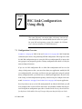
BSC Link Configuration Using dlicfg
7.1
7.2
8
.
.
.
.
.
.
.
.
.
.
.
.
.
.
.
.
.
.
.
.
.
.
.
.
.
.
.
.
.
.
.
.
.
.
.
.
.
.
.
.
.
.
.
.
.
.
.
.
.
.
.
.
.
.
.
.
.
.
.
.
.
.
.
.
.
.
.
.
.
.
.
.
.
.
.
.
.
.
.
.
.
.
.
.
.
.
.
.
.
.
.
.
.
.
.
.
.
.
.
.
.
.
.
.
.
.
.
.
.
.
.
.
.
.
.
.
.
.
.
.
.
.
.
.
.
.
.
.
.
.
.
.
.
.
.
.
.
.
.
.
.
.
.
.
.
.
.
.
.
.
.
.
.
.
.
.
.
.
.
.
.
.
.
.
.
.
.
.
.
.
.
.
.
.
.
.
.
.
.
.
.
.
.
.
.
.
.
.
.
.
.
.
.
.
.
.
.
.
.
.
.
.
.
.
.
.
.
.
.
.
.
.
.
.
.
.
.
.
.
.
.
.
.
.
.
.
.
.
.
.
.
.
.
.
.
.
.
.
.
.
.
.
.
.
.
.
.
.
.
.
.
.
.
.
.
.
.
.
.
.
.
.
.
.
.
.
.
.
.
.
.
.
.
.
.
.
.
.
.
.
.
.
.
.
.
.
.
.
.
.
.
.
.
.
.
.
.
.
.
.
.
.
.
.
.
.
.
.
.
.
.
.
.
.
.
.
.
.
.
.
.
.
.
.
.
.
.
.
.
.
.
.
.
.
.
.
.
.
.
.
.
.
.
.
.
.
.
.
.
.
.
.
.
.
.
.
.
.
.
.
.
.
.
.
.
.
.
.
.
.
.
.
.
.
.
.
.
.
.
.
.
.
.
.
.
.
.
.
.
.
.
.
.
.
.
.
.
.
.
.
.
.
.
.
.
.
.
.
.
.
.
.
.
.
.
.
.
.
.
.
.
.
.
.
.
.
.
.
.
.
.
.
.
.
.
.
.
.
.
.
.
.
.
.
.
.
.
.
.
.
.
.
.
.
.
.
.
.
.
.
.
.
.
.
.
.
.
.
.
.
.
.
.
.
.
.
.
.
.
.
.
.
.
.
.
.
.
.
.
.
.
.
.
.
.
.
.
.
.
.
.
.
.
.
.
.
.
.
.
.
.
.
.
.
.
.
.
.
.
.
.
.
.
.
.
.
.
.
.
.
.
.
.
.
.
.
.
.
.
.
.
.
.
.
.
.
.
.
.
.
.
.
.
.
.
.
.
.
.
.
.
.
.
.
.
.
.
.
.
.
.
.
.
.
.
.
.
.
.
.
.
.
.
.
.
.
.
.
.
163
164
165
166
166
167
167
168
168
169
169
170
170
170
173
173
174
175
175
176
177
178
178
178
179
180
181
181
182
182
182
183
Configuration Overview . . . . . . . . . . . . . . . . . . . . . . . . . . . 183
DLI Session Configuration . . . . . . . . . . . . . . . . . . . . . . . . . 188
DC 900-1340I
Contents
A
BSC 3270 Line Control Procedures
A.1 Control Station Procedures . . . . .
A.1.1 General Poll. . . . . . . . . . .
A.1.2 Device Selection . . . . . . . .
A.1.3 Specific Poll . . . . . . . . . . .
A.2 Tributary Station Procedures . . . .
A.2.1 Normal Mode. . . . . . . . . .
A.2.2 Test Mode . . . . . . . . . . . .
A.3 Line Up/Down Reporting . . . . . .
A.4 Virtual Device Procedures . . . . .
A.4.1 Virtual Printer Operation . . .
A.4.2 Virtual Display Operation . . .
A.4.3 3270 Command Checking . . .
A.4.4 BSC 3270 Sense/Status Message
A.5 Station Up/Down Reporting . . . .
A.6 DSR/DCD Up/Down Reporting . .
A.7 Freeway/Line Interface . . . . . . .
A.8 Modem Control Lines. . . . . . . .
A.9 Clock Signals. . . . . . . . . . . . .
A.10 Idle Line Condition . . . . . . . . .
B
193
.
.
.
.
.
.
.
.
.
.
.
.
.
.
.
.
.
.
.
.
.
.
.
.
.
.
.
.
.
.
.
.
.
.
.
.
.
.
.
.
.
.
.
.
.
.
.
.
.
.
.
.
.
.
.
.
.
.
.
.
.
.
.
.
.
.
.
.
.
.
.
.
.
.
.
.
.
.
.
.
.
.
.
.
.
.
.
.
.
.
.
.
.
.
.
.
.
.
.
.
.
.
.
.
.
.
.
.
.
.
.
.
.
.
.
.
.
.
.
.
.
.
.
.
.
.
.
.
.
.
.
.
.
.
.
.
.
.
.
.
.
.
.
.
.
.
.
.
.
.
.
.
.
.
.
.
.
.
.
.
.
.
.
.
.
.
.
.
.
.
.
.
.
.
.
.
.
.
.
.
.
.
.
.
.
.
.
.
.
.
.
.
.
.
.
.
.
.
.
.
.
.
.
.
.
.
.
.
.
.
.
.
.
.
.
.
.
.
.
.
.
.
.
.
.
.
.
.
.
.
.
.
.
.
.
.
.
.
.
.
.
.
.
.
.
.
.
.
.
.
.
.
.
.
.
.
.
.
.
.
.
.
.
.
.
.
.
.
.
.
.
.
.
.
.
.
.
.
.
.
.
.
.
.
.
.
.
.
.
.
.
.
.
.
.
.
.
.
.
.
.
.
.
.
.
.
.
.
.
.
.
.
.
.
.
.
.
.
.
.
.
.
.
.
.
.
.
.
.
.
.
.
.
.
.
.
.
.
.
.
.
.
.
.
.
.
.
.
.
.
.
.
.
.
.
.
.
.
.
.
.
.
.
.
.
.
.
.
.
.
.
.
.
.
.
.
.
.
.
.
BSC 2780/3780 Control Procedures
B.1 BSC 2780/3780 Communications Control . . . . . . . . . . . . . .
B.1.1 BSC 2780/3780 Software Initialization . . . . . . . . . . . . .
B.1.2 Normal Link Start . . . . . . . . . . . . . . . . . . . . . . . .
B.1.3 Signon Procedure using BSC 2780/3780 Software Commands
B.1.4 Data Reception . . . . . . . . . . . . . . . . . . . . . . . . . .
B.1.5 Normal Data Transmission . . . . . . . . . . . . . . . . . . .
B.1.6 Priority Data Reception . . . . . . . . . . . . . . . . . . . . .
B.1.7 Recoverable Errors In Transmission . . . . . . . . . . . . . . .
B.1.8 Unrecoverable Errors In Transmission . . . . . . . . . . . . .
B.1.9 Normal Link Stop . . . . . . . . . . . . . . . . . . . . . . . .
B.2 DSR/DCD Up/Down Reporting . . . . . . . . . . . . . . . . . . .
B.3 Freeway/Line Interface . . . . . . . . . . . . . . . . . . . . . . . .
B.4 Modem Control Lines. . . . . . . . . . . . . . . . . . . . . . . . .
B.5 Clock Signals. . . . . . . . . . . . . . . . . . . . . . . . . . . . . .
DC 900-1340I
. 193
. 193
. 194
. 195
. 195
. 196
. 196
. 196
. 197
. 197
. 197
. 200
. 204
. 206
. 206
. 207
. 207
. 208
. 208
209
.
.
.
.
.
.
.
.
.
.
.
.
.
.
.
.
.
.
.
.
.
.
.
.
.
.
.
.
.
.
.
.
.
.
.
.
.
.
.
.
.
.
. 209
. 210
. 211
. 212
. 216
. 217
. 218
. 220
. 221
. 223
. 224
. 224
. 224
. 224
9
BSC Programmer’s Guide
B.6
Idle Line Condition . . . . . . . . . . . . . . . . . . . . . . . . . . . . . 225
C
ASCII Translation Tables
227
D
Error Codes
233
E
BSC Loopback Test Program
237
E.1
F
Loopback Test Programs. . . . . . . . . . . . . . . . . . . . . . . . . . . 237
BSC Detailed Command and Response Formats
F.1
BSC Protocol Processing. . . . . . . . .
F.1.1 Session Attach . . . . . . . . . . . .
F.1.2 Set Buffer Size . . . . . . . . . . . .
F.1.3 Link Configuration . . . . . . . . .
F.1.4 Link Enabling (Bind) . . . . . . . .
F.1.5 Data Transfer . . . . . . . . . . . .
F.1.6 Link Disabling (Unbind) . . . . . .
F.1.7 Session Detach . . . . . . . . . . .
F.2 Command/Response Header Summary
F.3 Response Header Format . . . . . . . .
Index
10
.
.
.
.
.
.
.
.
.
.
.
.
.
.
.
.
.
.
.
.
243
.
.
.
.
.
.
.
.
.
.
.
.
.
.
.
.
.
.
.
.
.
.
.
.
.
.
.
.
.
.
.
.
.
.
.
.
.
.
.
.
.
.
.
.
.
.
.
.
.
.
.
.
.
.
.
.
.
.
.
.
.
.
.
.
.
.
.
.
.
.
.
.
.
.
.
.
.
.
.
.
.
.
.
.
.
.
.
.
.
.
.
.
.
.
.
.
.
.
.
.
.
.
.
.
.
.
.
.
.
.
.
.
.
.
.
.
.
.
.
.
.
.
.
.
.
.
.
.
.
.
.
.
.
.
.
.
.
.
.
.
.
.
.
.
.
.
.
.
.
.
.
.
.
.
.
.
.
.
.
.
243
243
244
244
244
244
245
245
246
257
259
DC 900-1340I
List of Figures
Figure 1–1:
Freeway Configuration . . . . . . . . . . . . . . . . . . . . . . . . . . . . 26
Figure 1–2:
Embedded ICP Configuration . . . . . . . . . . . . . . . . . . . . . . . . 27
Figure 1–3:
A Typical Freeway Server Environment . . . . . . . . . . . . . . . . . . . 29
Figure 2–1:
Normal 2780 Text Block. . . . . . . . . . . . . . . . . . . . . . . . . . . . 38
Figure 2–2:
Transparent 2780 Text Block . . . . . . . . . . . . . . . . . . . . . . . . . 39
Figure 2–3:
Normal 3780 Text Block. . . . . . . . . . . . . . . . . . . . . . . . . . . . 40
Figure 2–4:
Transparent 3780 Text Block . . . . . . . . . . . . . . . . . . . . . . . . . 40
Figure 3–1:
“C” Definition of DLI Optional Arguments Structure . . . . . . . . . . . 54
Figure 3–2:
Link Configuration Block with Two Options . . . . . . . . . . . . . . . . 60
Figure 3–3:
Set Poll List Command Example . . . . . . . . . . . . . . . . . . . . . . . 63
Figure 3–4:
BSC 3270 Specific Poll Format . . . . . . . . . . . . . . . . . . . . . . . . 66
Figure 3–5:
Example Create Virtual 3270 Devices . . . . . . . . . . . . . . . . . . . . 68
Figure 3–6:
BSC 3270 Device Status Bits . . . . . . . . . . . . . . . . . . . . . . . . . 76
Figure 5–1:
“C” Definition of DLI Optional Arguments Structure . . . . . . . . . . . 114
Figure 5–2:
Link Configuration Block with Two Options . . . . . . . . . . . . . . . . 120
Figure 5–3:
BSC 2780/3780 Link Trace Data Format . . . . . . . . . . . . . . . . . . . 137
Figure 5–4:
Client Transparent 2780 Record Format . . . . . . . . . . . . . . . . . . . 148
Figure 5–5:
BSC 2780/3780 Modified Transparent 2780 Record Format . . . . . . . . 149
Figure 6–1:
Transmit with Disabled Message Blocking Option. . . . . . . . . . . . . . 171
Figure 6–2:
Transmit with Data Blocking Option . . . . . . . . . . . . . . . . . . . . . 171
Figure 6–3:
Receive with Disabled Message Blocking Option. . . . . . . . . . . . . . . 172
Figure 6–4:
Receive with Data Blocking Option . . . . . . . . . . . . . . . . . . . . . . 172
Figure 7–1:
DLI and TSI Configuration Process . . . . . . . . . . . . . . . . . . . . . 187
Figure 7–2:
Example DLI Configuration File for Two BSC 3270 Links . . . . . . . . . 189
Figure A–1:
General Poll Format . . . . . . . . . . . . . . . . . . . . . . . . . . . . . . 194
DC 900-1340I
11
BSC Programmer’s Guide
Figure A–2:
Device Selection Sequence. . . . . . . . . . . . . . . . . . . . . . . . . . 195
Figure A–3:
Normal Operation for Virtual Printer . . . . . . . . . . . . . . . . . . . 198
Figure A–4:
Printer Error During Printout. . . . . . . . . . . . . . . . . . . . . . . . 199
Figure A–5:
Normal Operation of Virtual Display . . . . . . . . . . . . . . . . . . . . 200
Figure A–6:
BSC 3270 Command Checking . . . . . . . . . . . . . . . . . . . . . . . 201
Figure A–7:
RVI Ignored by BSC 3270 Master . . . . . . . . . . . . . . . . . . . . . . 202
Figure A–8:
WACK Ignored by BSC 3270 Master . . . . . . . . . . . . . . . . . . . . 203
Figure A–9:
BSC 3270 Sense/Status Bytes . . . . . . . . . . . . . . . . . . . . . . . . 204
Figure A–10: BSC 3270 Status Message Format . . . . . . . . . . . . . . . . . . . . . . 204
Figure B–1:
Software Initialization Sequence . . . . . . . . . . . . . . . . . . . . . . 210
Figure B–2:
Start Link Sequence Using Two Commands . . . . . . . . . . . . . . . . 211
Figure B–3:
Signon Procedure (Transmit with Immediate Data) . . . . . . . . . . . . 213
Figure B–4:
Signon Procedure (Transmit with Delayed Data) . . . . . . . . . . . . . 214
Figure B–5:
Signon Procedure (Receive) . . . . . . . . . . . . . . . . . . . . . . . . . 215
Figure B–6:
Data Reception Sequence . . . . . . . . . . . . . . . . . . . . . . . . . . 216
Figure B–7:
Normal Data Transmission Sequence . . . . . . . . . . . . . . . . . . . . 217
Figure B–8:
Two-message Sequence with Priority Message Interrupt . . . . . . . . . 219
Figure B–9:
Recoverable Error Sequence . . . . . . . . . . . . . . . . . . . . . . . . . 220
Figure B–10: No Response from the Remote Station . . . . . . . . . . . . . . . . . . . 221
Figure B–11: Transmission Aborted by the Remote Station . . . . . . . . . . . . . . . 222
Figure B–12: Link Stop Sequence . . . . . . . . . . . . . . . . . . . . . . . . . . . . . 223
12
DC 900-1340I
List of Tables
Table 2–1:
BSC 3270 Session Access Modes . . . . . . . . . . . . . . . . . . . . . . . . 36
Table 2–2:
BSC 3270 Access Modes for Various Operations . . . . . . . . . . . . . . . 37
Table 2–3:
BSC 2780/3780 Session Access Modes . . . . . . . . . . . . . . . . . . . . . 43
Table 2–4:
BSC 2780/3780 Access Modes for Various Operations . . . . . . . . . . . . 44
Table 3–1:
DLI Call Sequence for BSC 3270 (Blocking I/O) . . . . . . . . . . . . . . . 50
Table 3–2:
DLI Call Sequence for BSC 3270 (Non-blocking I/O) . . . . . . . . . . . . 51
Table 3–3:
DLI Functions: Syntax and Parameters (Listed in Typical Call Order). . . . 53
Table 3–4:
Categories for BSC 3270 dlWrite Requests . . . . . . . . . . . . . . . . . . . 56
Table 3–5:
Device Status Values . . . . . . . . . . . . . . . . . . . . . . . . . . . . . . 69
Table 3–6:
Buffer Report Definition . . . . . . . . . . . . . . . . . . . . . . . . . . . . 71
Table 3–7:
BSC 3270 Statistics Report Definition . . . . . . . . . . . . . . . . . . . . . 73
Table 3–8:
Status Report Definition . . . . . . . . . . . . . . . . . . . . . . . . . . . . 74
Table 3–9:
BSC 3270 Device Status Conditions and Responses. . . . . . . . . . . . . . 77
Table 3–10: BSC 3270 Response Codes . . . . . . . . . . . . . . . . . . . . . . . . . . . 81
Table 4–1:
BSC 3270 Link Configuration Options and Settings . . . . . . . . . . . . . 86
Table 4–2:
Modem Control Option Settings. . . . . . . . . . . . . . . . . . . . . . . . 96
Table 5–1:
DLI Call Sequence for BSC 2780/3780 (Blocking I/O) . . . . . . . . . . . . 110
Table 5–2:
DLI Call Sequence for BSC 2780/3780 (Non-blocking I/O) . . . . . . . . . 111
Table 5–3:
DLI Functions: Syntax and Parameters (Listed in Typical Call Order). . . . 113
Table 5–4:
Categories for BSC 2780/3780 dlWrite Requests . . . . . . . . . . . . . . . . 116
Table 5–5:
BSC 2780/3780 Error Responses on Poll Failure . . . . . . . . . . . . . . . 129
Table 5–6:
Autodial Start Acknowledge Errors Returned . . . . . . . . . . . . . . . . . 132
Table 5–7:
Trace Event Numbers . . . . . . . . . . . . . . . . . . . . . . . . . . . . . . 138
Table 5–8:
Buffer Report Definition . . . . . . . . . . . . . . . . . . . . . . . . . . . . 140
Table 5–9:
BSC 2780/3780 Statistics Report Definition . . . . . . . . . . . . . . . . . . 141
DC 900-1340I
13
BSC Programmer’s Guide
Table 5–10: BSC 2780/3780 Status Report Definition. . . . . . . . . . . . . . . . . . . 143
Table 5–11: Last Event Codes for Link Status Report . . . . . . . . . . . . . . . . . . . 145
Table 5–12: BSC 2780/3780 Response Codes . . . . . . . . . . . . . . . . . . . . . . . 151
Table 6–1:
BSC 2780/3780 Link Configuration Options and Settings . . . . . . . . . 156
Table 6–2:
Recommended Data Translation Settings . . . . . . . . . . . . . . . . . . 165
Table 6–3:
Modem Control Option Settings . . . . . . . . . . . . . . . . . . . . . . . 169
Table 7–1:
BSC 3270 ICP Link Parameters and Defaults for Using dlicfg . . . . . . . 190
Table 7–2:
BSC 2780/3780 ICP Link Parameters and Defaults for Using dlicfg . . . . 191
Table A–1: Sense/Status Bit Combinations . . . . . . . . . . . . . . . . . . . . . . . . 205
Table A–2: Condition Changes that Generate Responses to General Polls . . . . . . . 205
Table A–3: EIA-232 Modem Control Lines . . . . . . . . . . . . . . . . . . . . . . . . 207
Table A–4: EIA-232 Clock Signals. . . . . . . . . . . . . . . . . . . . . . . . . . . . . 208
Table B–1:
EIA-232 Modem Control Lines . . . . . . . . . . . . . . . . . . . . . . . . 225
Table B–2:
EIA-232 Clock Signals. . . . . . . . . . . . . . . . . . . . . . . . . . . . . 226
Table C–1: ASCII to EBCDIC Translation Table 1 . . . . . . . . . . . . . . . . . . . . 228
Table C–2: EBCDIC to ASCII Translation Table 1 . . . . . . . . . . . . . . . . . . . . 229
Table C–3: ASCII to EBCDIC Translation Table 2 . . . . . . . . . . . . . . . . . . . . 230
Table C–4: EBCDIC to ASCII Translation Table 2 . . . . . . . . . . . . . . . . . . . . 231
Table D–1: BSC Error Codes . . . . . . . . . . . . . . . . . . . . . . . . . . . . . . . 234
Table E–1:
BSC 3270 Loopback Test Programs and Directories . . . . . . . . . . . . . 237
Table E–2:
BSC 3780 Loopback Test Programs and Directories . . . . . . . . . . . . . 238
Table F–1:
Command/Response Codes. . . . . . . . . . . . . . . . . . . . . . . . . . 246
Table F–2:
DLI_ICP_CMD_ATTACH Command and Response
. . . . . . . . . . . . . . . . 247
Table F–3:
DLI_ICP_CMD_DETACH Command and Response
. . . . . . . . . . . . . . . . 248
Table F–4:
DLI_ICP_CMD_BIND Command and Response .
Table F–5:
DLI_ICP_CMD_UNBIND Command and Response
Table F–6:
DLI_PROT_SET_BUF_SIZE Command and Response
Table F–7:
BSC 3270 General Commands and Responses . . . . . . . . . . . . . . . . 252
Table F–8:
BSC 3270 Device Creation and Modification Commands and Responses . 253
Table F–9:
BSC 2780/3780 General Commands and Responses. . . . . . . . . . . . . 254
. . . . . . . . . . . . . . . . . 249
. . . . . . . . . . . . . . . . 250
. . . . . . . . . . . . . . . 251
Table F–10: DLI_PROT_SET_TRANS_TABLE Command and Response . . . . . . . . . . . . . 255
Table F–11: BSC Transmit Data Commands and Response. . . . . . . . . . . . . . . . 256
14
DC 900-1340I
List of Tables
Table F–12: BSC Receive Data Responses . . . . . . . . . . . . . . . . . . . . . . . . . . 257
DC 900-1340I
15
BSC Programmer’s Guide
16
DC 900-1340I
Preface
Purpose of Document
This document describes the operation and programming interface required to use
Protogate’s Binary Synchronous Communications (BSC) product for Protogate’s
Freeway communications server or embedded ICP.
Note
In this document, the DLI API interface applies to both a Freeway
server or an embedded ICP using DLITE. For the embedded ICP,
also refer to the user’s guide for your ICP and operating system
(for example, the ICP2432 User’s Guide for Windows NT (DLITE
Interface)).
Intended Audience
This document should be read by programmers who are interfacing an application program to a BSC 3270 and/or a BSC 2780/3780 environment. You should understand the
data link interface (DLI), as explained in the Freeway Data Link Interface Reference
Guide.
Required Equipment
The BSC product requires the following two major hardware components to operate:
DC 900-1340I
17
BSC Programmer’s Guide
•
a Freeway communications server or an embedded ICP that runs the communications software
•
a client computer that runs the following:
•
TCP/IP (for a Freeway server)
•
Data link interface (DLI)
•
the user application program
Organization of Document
Chapter 1 is an overview of Freeway and the BSC product.
Chapter 2 summarizes the basic communication protocol formats available on the BSC
software package.
Chapter 3 describes how to use the data link interface (DLI) between the client application program and the BSC 3270 communications software running on the Freeway ICP.
Chapter 4 describes the link configuration options available on the BSC 3270 software
package.
Chapter 5 describes how to use the data link interface (DLI) between the client application program and the BSC 2780/3780 communications software running on the Freeway ICP.
Chapter 6 describes the link configuration options available on the BSC 2780/3780 software package.
Chapter 7 describes how to configure the BSC link options using the dlicfg program.
Appendix A describes the line control procedures for BSC 3270.
Appendix B describes the line control procedures for BSC 2780/3780.
18
DC 900-1340I
Preface
Appendix C contains the ASCII/EBCDIC code translation tables.
Appendix D describes error handling and lists the error codes.
Appendix E describes the BSC loopback test program.
Appendix F gives detailed examples of command and response header formats.
11/16/98
Leslie:
Changed
appropriate
documents to
DC-908-xxxx
(Export
Restricted).
Most are in
the
Military/Gove
rnment
separate table.
Remove
“Freeway”
from several.
Protogate References
The following documents provide useful supporting information, depending on the
customer’s particular hardware and software environments. Most documents are available on-line at Protogate’s web site, www.protogate.com.
General Product Overviews
•
•
Freeway 1100 Technical Overview
25-000-0419
ICP2432 Technical Overview
25-000-0420
Hardware Support
Techpubs:
Don’t delete
the “Other
Helpful
Documents”
(separate
table at end of
References).
Also set “space
below” on first
table = 0 pt.
•
•
•
•
•
•
•
•
Freeway 3100 Hardware Installation Guide
DC 900-2002
Freeway 3200 Hardware Installation Guide
DC 900-2003
Freeway 3400 Hardware Installation Guide
DC 900-2004
Freeway 3600 Hardware Installation Guide
DC 900-2005
Freeway 1100/1150 Hardware Installation Guide
DC 900-1370
Freeway 2000/4000 Hardware Installation Guide
DC 900-1331
Freeway ICP6000R/ICP6000X Hardware Description
DC 900-1020
ICP6000(X)/ICP9000(X) Hardware Description and Theory of
Operation
DC 900-0408
•
•
•
•
•
ICP2424 Hardware Description and Theory of Operation
DC 900-1328
ICP2432 Hardware Description and Theory of Operation
DC 900-1501
ICP2432 Hardware Installation Guide
DC 900-1502
ICP2432B Hardware Description and Theory of Operation
DC 900-2006
ICP2432B Hardware Installation Guide
DC 900-2009
DC 900-1340I
19
BSC Programmer’s Guide
Freeway Software Installation Support
•
•
•
•
•
Freeway Server User’s Guide
DC 900-1333
Freeway Software Release Addendum: Client Platforms
DC 900-1555
Getting Started with Freeway 1100/1150
DC 900-1369
Getting Started with Freeway 2000/4000
DC 900-1330
Loopback Test Procedures
DC 900-1533
Embedded ICP Installation and Programming Support
•
•
•
•
ICP2432 User’s Guide for Tru64 UNIX
DC 900-1513
ICP2432 User’s Guide for OpenVMS Alpha (DLITE Interface)
DC 900-1516
ICP2432 User’s Guide for Windows NT (DLITE Interface)
DC 900-1514
DC 900-1512
ICP2432 User Guide for Solaris STREAMS
Application Program Interface (API) Programming Support
•
•
•
•
Freeway Data Link Interface Reference Guide
DC 900-1385
Freeway QIO/SQIO API Reference Guide
DC 900-1355
Freeway Server-Resident Application Programmer’s Guide
DC 900-1325
Freeway Transport Subsystem Interface Reference Guide
DC 900-1386
Socket Interface Programming Support
•
Freeway Client-Server Interface Control Document
DC 900-1303
Toolkit Programming Support
•
•
•
•
OS/Impact Programmer’s Guide
DC 900-1030
Protocol Software Toolkit Programmer’s Guide
DC 900-1338
OS/Protogate Programmer Guide
DC 900-2008
Protocol Software Toolkit Programmer’s Guide (ICP2432B)
DC 900-2007
Protocol Support
•
•
•
•
20
ADCCP NRM Programmer’s Guide
DC 900-1317
Asynchronous Wire Service (AWS) Programmer’s Guide
DC 900-1324
Addendum: Embedded ICP2432 AWS Programmer’s Guide
DC 900-1557
BSC Programmer’s Guide
DC 900-1340
DC 900-1340I
Preface
•
•
•
•
•
•
•
•
•
•
•
•
•
•
BSCDEMO User’s Guide
DC 900-1349
BSCTRAN Programmer’s Guide
DC 900-1406
DDCMP Programmer’s Guide
DC 900-1343
Freeway AUTODIN Programmer’s Guide
DC 908-1558
Freeway FMP Programmer’s Guide
DC 900-1339
Freeway Marketfeed 2000 Programmer’s Guide
DC 900-1346
Freeway MRS Protocol Programmer’s Guide
DC 900-1565
Freeway SIO STD-1300 Programmer’s Guide
DC 908-1559
Freeway SWIFT and CHIPS Programmer’s Guide
DC 900-1344
Military/Government Protocols Programmer’s Guide
DC 900-1602
SIO STD-1200A (Rev. 1) Programmer’s Guide
DC 908-1359
X.25 Call Service API Guide
DC 900-1392
X.25/HDLC Configuration Guide
DC 900-1345
X.25 Low-Level Interface
DC 900-1307
Other helpful documents:
•
General Information — Binary Synchronous Communications, GA27-3004
IBM
•
•
•
3274 Control Unit Description and Programmer’s Guide, IBM
GA23-0061
Component Description: IBM 2780 Data Transmission Terminal
Component Description: IBM 3780 Data Transmission Terminal
Document Conventions
This document follows the most significant byte first (MSB) and most significant word
first (MSW) conventions for bit-numbering and byte-ordering. In all packet transfers
between the client applications and the ICPs, the ordering of the byte stream is preserved.
The term “Freeway” refers to any of the Freeway server models (for example, Freeway
500/3100/3200/3400 PCI-bus servers, Freeway 1000 ISA-bus servers, or Freeway
2000/4000/8800 VME-bus servers). References to “Freeway” also may apply to an
DC 900-1340I
21
BSC Programmer’s Guide
embedded ICP product using DLITE (for example, the embedded ICP2432 using
DLITE on a Windows NT system).
Physical “ports” on the ICPs are logically referred to as “links.” However, since port and
link numbers are usually identical (that is, port 0 is the same as link 0), this document
uses the term “link.”
Program code samples are written in the “C” programming language.
Revision History
The revision history of the BSC Programmer’s Guide, Protogate document DC 9001340I, is recorded below:
Revision
Ron said the
following
should be
documented
somewhere
(I’m not sure):
“The address
that
BSC2780/3780
is installed at
in the
bscXload.unx
file has
changed.”
Release Date
Description
DC 900-1340A
September 1994 Original release
DC 900-1340B
October 1994
•
•
Modify the 3270 text addressing option (Section 4.22)
Modify the Freeway 1000 electrical interface option
(Section 4.24)
DC 900-1340C
November 1994
•
•
•
Minor modifications and updated error codes
Update file names for software release 2.1
Change the usICPStatus field to iICPStatus and change
the usProtModifier field to iProtModifier (page 54 and
page 114)
DC 900-1340D
February 1995
•
•
Minor modifications
New and updated BSC 2780/3780 options in
Chapter 5, Chapter 6 and Chapter 7.
DC 900-1340E
May 1995
Minor modifications
Modify Line Type option (Section 6.31 on page 182)
DC 900-1340F
January 1996
•
•
•
•
•
22
Minor modifications throughout document
Add dlControl function to Table 3–3 on page 53 and
Table 5–3 on page 113
Add Windows NT to Chapter 7 and Appendix E
DC 900-1340I
Preface
Revision
DC 900-1340G
Release Date
April 1998
Description
•
•
•
DC 900-1340H
November 1998
•
•
•
•
•
DC 900-1340I
December 2002
•
Modify Section 1.1 through Section 1.4.
Changes to BSC 3270: minor changes to Section 3.1.2
on page 47 and Section 3.2 on page 50, add
dlpErrString function (Table 3–3 on page 53)
Changes to BSC 2780/3780: minor changes to
Section 5.1.2 on page 107 and Section 5.2 on
page 110, add dlpErrString function (Table 5–3 on
page 113) add Wait for Bid Delay option (Section 6.14
on page 168) and Line Turnaround Delay option
(Section 6.23 on page 178)
Minor changes to Chapter 7and Appendix E.
Add dlSyncSelect function (Table 3–3 on page 53).
Add permanent hold with notify EOM line control
option (Section 6.20 on page 176 and Table 7–2 on
page 191).
Modify Appendix E to support only non-blocking I/O
loopback test.
Add Appendix F, “BSC Detailed Command and
Response Formats.”
Update contact information for Protogate, Inc. Adjust
figures, drawings, and fonts. Add references for Freeway 3x00 and ICP2432B.
Customer Support
If you are having trouble with any Protogate product, call us at (858) 451-0865 Monday
through Friday between 8 a.m. and 5 p.m. Pacific time.
You can also fax your questions to us at (877) 473-0190 any time. Please include a cover
sheet addressed to “Customer Service.”
We are always interested in suggestions for improving our products. You can use the
report form in the back of this manual to send us your recommendations.
DC 900-1340I
23
BSC Programmer’s Guide
24
DC 900-1340I
Chapter
1
Introduction
1.1 Product Overview
Most recent
modification
date:
03/25/98
Leslie:
Remove
“Freeway
Embedded”
and just say
“embedded
ICP” (as an
interim fix
prior to BIG
makeover).
Protogate provides a variety of wide-area network (WAN) connectivity solutions for
real-time financial, defense, telecommunications, and process-control applications.
Protogate’s Freeway server offers flexibility and ease of programming using a variety of
LAN-based server hardware platforms. Now a consistent and compatible embedded
intelligent communications processor (ICP) product offers the same functionality as
the Freeway server, allowing individual client computers to connect directly to the
WAN.
Both Freeway and the embedded ICP use the same data link interface (DLI). Therefore,
migration between the two environments simply requires linking your client application with the proper library. Various client operating systems are supported (for example, UNIX, VMS, and Windows NT).
Protogate protocols that run on the ICPs are independent of the client operating system
and the hardware platform (Freeway or embedded ICP).
1.1.1 Freeway Server
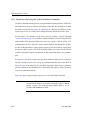
Protogate’s Freeway communications servers enable client applications on a local-area
network (LAN) to access specialized WANs through the DLI. The Freeway server can be
any of several models (for example, Freeway 1100, Freeway 2000/4000, or Freeway
8000/8800). The Freeway server is user programmable and communicates in real time.
It provides multiple data links and a variety of network services to LAN-based clients.
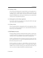
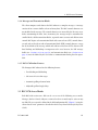
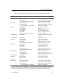
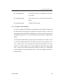
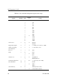
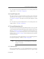
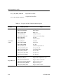
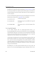
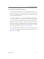
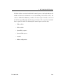
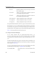
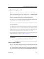
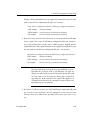
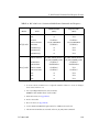
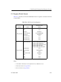
Figure 1–1 shows the Freeway configuration.
DC 900-1340I
25
BSC Programmer’s Guide
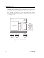
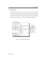
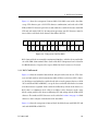
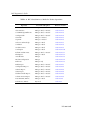
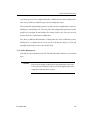
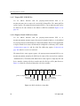
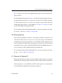
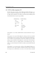
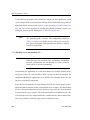
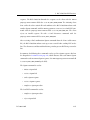
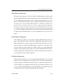
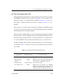
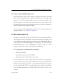
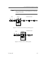
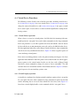
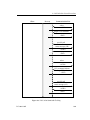
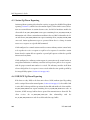
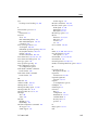
To maintain high data throughput, Freeway uses a multi-processor architecture to support the LAN and WAN services. The LAN interface is managed by a single-board computer, called the server processor. It uses the commercially available VxWorks
operating system to provide a full-featured base for the LAN interface and layered services needed by Freeway.
Freeway
WAN Protocol
Options
●
Commercial
Financial
Government
●
Server Software
ICP
●
Industry Standard Bus
WAN
Interface
Processors
Military
SCADA
ICP
Ethernet LAN
DLI
API
Application
Application
Application
Client 1
Client 2
Client n
●
●
●
DLI
API
3413
DLI
API
Figure 1–1: Freeway Configuration
26
DC 900-1340I
1: Introduction
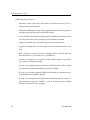
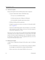
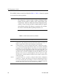
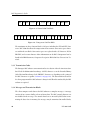
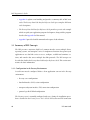
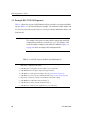
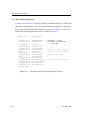
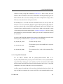
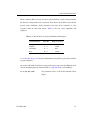
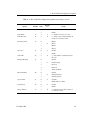
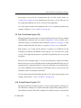
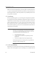
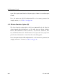
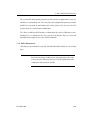
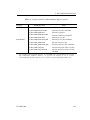
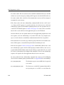
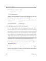
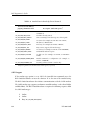
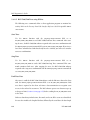
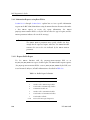
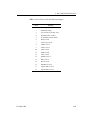
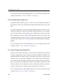
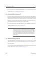
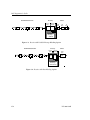
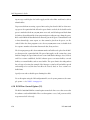
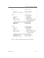
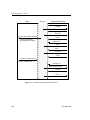
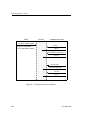
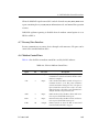
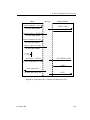
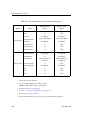
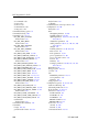
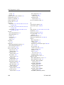
1.1.2 Embedded ICP
The embedded ICP connects your client computer directly to the WAN (for example,
using Protogate’s ICP2432 PCIbus board). The embedded ICP provides client applications with the same WAN connectivity as the Freeway server, using the same data link
interface. The ICP runs the communication protocol software using Protogate’s
real-time operating system. Figure 1–2 shows the embedded ICP configuration.
Client Computer
Client DLITE
API
Appl 1
ICP Device Driver
Industry Standard Bus
●
●
●
Client DLITE
API
Appl 2
WAN Protocol
Options
Embedded ICP
Commercial
Financial
Government
Protogate
WAN Protocol
Software
Military
SCADA
3414
Client DLITE
Appl n
API
Figure 1–2: Embedded ICP Configuration
DC 900-1340I
27
BSC Programmer’s Guide
Summary of product features:
•
Provision of WAN connectivity either through a LAN-based Freeway server or
directly using an embedded ICP
•
Elimination of difficult LAN and WAN programming and systems integration by
providing a powerful and consistent data link interface
•
Variety of off-the-shelf communication protocols available from Protogate which
are independent of the client operating system and hardware platform
•
Support for multiple WAN communication protocols simultaneously
•
Support for multiple ICPs (two, four, eight, or sixteen communication lines per
ICP)
•
Wide selection of electrical interfaces including EIA-232, EIA-449, EIA-485,
EIA-530, EIA-562, V.35, ISO-4903 (V.11), and MIL-188
•
Creation of customized server-resident and ICP-resident software, using Protogate’s software development toolkits
•
Freeway server standard support for Ethernet and Fast Ethernet LANs running
the transmission control protocol/internet protocol (TCP/IP)
•
Freeway server standard support for FDDI LANs running the transmission control protocol/internet protocol (TCP/IP)
•
Freeway server management and performance monitoring with the simple network management protocol (SNMP), as well as interactive menus available
through a local console, telnet, or rlogin
28
DC 900-1340I
1: Introduction
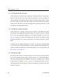
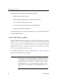
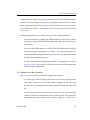
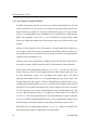
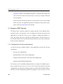
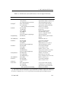
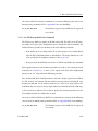
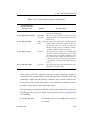
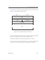
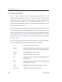
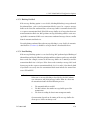
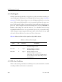
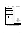
1.2 Freeway Client-Server Environment
The Freeway server acts as a gateway that connects a client on a local-area network to a
wide-area network. Through Freeway, a client application can exchange data with a
remote data link application. Your client application must interact with the Freeway
server and its resident ICPs before exchanging data with the remote data link application.
One of the major Freeway server components is the message multiplexor (MsgMux)
that manages the data traffic between the LAN and the WAN environments. The client
application typically interacts with the Freeway MsgMux through a TCP/IP BSD-style
socket interface (or a shared-memory interface if it is a server-resident application
(SRA)). The ICPs interact with the MsgMux through the DMA and/or shared-memory
interface of the industry-standard bus to exchange WAN data. From the client application’s point of view, these complexities are handled through a simple and consistent
data link interface (DLI), which provides dlOpen, dlWrite, dlRead, and dlClose functions.
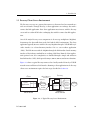
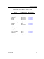
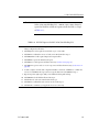
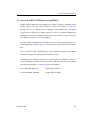
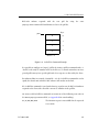
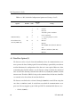
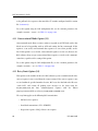
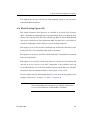
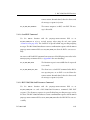
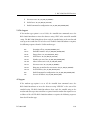
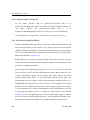
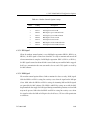
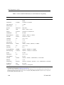
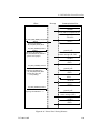
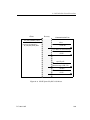
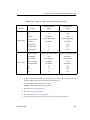
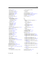
Figure 1–3 shows a typical Freeway connected to a locally attached client by a TCP/IP
network across an Ethernet LAN interface. Running a client application in the Freeway
client-server environment requires the basic steps described in Section 1.4.
Client
Application DLI TSI
TCP/IP
TCP/IP
Socket Interface
client_1
192.52.107.99
Freeway
SRA
T
S msgmux
I
ICP0
ICP1
WAN
protocols
ICP2
ICP3
3125
Shared Memory
Interface
Ethernet
Industry
Standard Bus
Client
freeway_0
192.52.107.100
Figure 1–3: A Typical Freeway Server Environment
DC 900-1340I
29
BSC Programmer’s Guide
1.2.1 Establishing Freeway Server Internet Addresses
The Freeway server must be addressable in order for a client application to communicate with it. In the Figure 1–3 example, the TCP/IP Freeway server name is freeway2,
and its unique Internet address is 192.52.107.100. The client machine where the client
application resides is client1, and its unique Internet address is 192.52.107.99. Refer to
the Freeway Server User’s Guide to initially set up your Freeway and download the operating system, server, and protocol software to Freeway.
1.3 Embedded ICP Environment
Refer to the user’s guide for your embedded ICP and operating system (for example, the
ICP2432 User’s Guide for Windows NT (DLITE Interface)) for software installation and
setup instructions. The user’s guide also gives additional information regarding the data
link interface (DLI) and embedded programming interface descriptions for your specific embedded environment. Refer back to Figure 1–2 on page 27 for a diagram of the
embedded ICP environment. Running a client application in the embedded ICP environment requires the basic steps described in Section 1.4
1.4 Client Operations
1.4.1 Defining the DLI and TSI Configuration
You must define the DLI sessions and the transport subsystem interface (TSI) connections between your client application and Freeway (or an embedded ICP). To accomplish this, you first define the configuration parameters in DLI and TSI ASCII
configuration files, and then you run two preprocessor programs, dlicfg and tsicfg, to
create binary configuration files (see Chapter 7). The dlInit function uses the binary
configuration files to initialize the DLI environment.
30
DC 900-1340I
1: Introduction
1.4.2 Opening a Session
After the DLI and TSI configurations are properly defined, your client application uses
the dlOpen function to establish a DLI session with an ICP link. As part of the session
establishment process, the DLI establishes a TSI connection with the Freeway MsgMux
through the TCP/IP BSD-style socket interface for the Freeway server, or directly to the
client driver for the embedded ICP environment.
1.4.3 Exchanging Data with the Remote Application
After the link is enabled, the client application can exchange data with the remote application using the dlWrite and dlRead functions.
1.4.4 Closing a Session
When your application finishes exchanging data with the remote application, it calls the
dlClose function to disable the ICP link, close the session with the ICP, and disconnect
from Freeway (or the embedded ICP).
1.5 BSC Product Overview
The Protogate Binary Synchronous Communications (BSC) product is a software package that allows applications running on the client to communicate through one or more
serial links to devices using the IBM BSC 3270 and/or BSC 2780/3780 protocol.
Each BSC serial link handles all low-level protocol activity thus freeing the client computer to perform other tasks. User-written client application programs interface to the
BSC software through the Freeway DLI.
Each BSC serial link can be configured as a 2780/3780 link, a 3270 control station (similar to an IBM 3705 communications controller) or a 3270 tributary station (similar to
an IBM 3274 cluster controller). Each link operates independently of other links on the
same server and can be configured with different communication options.
DC 900-1340I
31
BSC Programmer’s Guide
1.5.1 Software Description
Protogate’s BSC product includes the following major software components:
•
A group of communications software downloadable images:
1. Freeway server or embedded ICP software
2. Real-time operating system (OS/Impact or OS/Protogate)
3. BSC 3270 and BSC 2780/3780 communications software
•
DLI library for linking with client applications
•
A loopback test programs (bsc3270alp.c or bsc3780alp.c) to check product installation (see Appendix E)
1/96 Leslie: At
one time we
were going to
include
BSCTRAN
with the BSC
product, then
changed our
minds. The
following
bullet should
be added if we
ever re-change
our minds:
An interactive
file transfer
program
(bsctran) that
allows a user
to move a file
over a BSC
•
An interactive demonstration program (bscdemo) that allows a user to send individual commands to the BSC software on Freeway. The bscdemo program is
described in the BSCDEMO User’s Guide.
The Freeway Server User’s Guide or the user’s guide for your particular embedded ICP
and operating system (for example, the ICP2432 User’s Guide for Windows NT (DLITE
Interface)) describes the software installation procedures. The DLI provides an interface
by which data is exchanged between the client application and Freeway; refer to the
Freeway Data Link Interface Reference Guide.
1.5.2 Hardware Description
A typical Freeway configuration of Protogate’s BSC product requires the following
hardware:
•
Freeway communications server (for example, Freeway 1100, Freeway 2000 or
Freeway 4000) or an embedded ICP (for example the PCIbus ICP2432)
•
32
Ethernet connection to a client running TCP/IP (for a Freeway server)
DC 900-1340I
Chapter
2
BSC Protocol Summary
2.1 BSC 3270 Protocol Implementation
The Protogate Binary Synchronous Communications (BSC) product is a software package that allows applications running on the client to communicate through one or more
serial ports (links) to devices using the IBM BSC 3270 and/or the BSC 2780/3780 protocol.
Each BSC serial link handles all low-level protocol activity thus freeing the client processor to perform other tasks. User-written client application programs interface to the
BSC software through the Freeway DLI functions, described in Chapter 3 and
Chapter 5.
Each BSC serial link can be configured as a 2780/3780 link, a 3270 control station (similar to an IBM 3705 communications controller) or a 3270 tributary station (similar to
an IBM 3274 cluster controller). Each link operates independently of other links on the
same server and can be configured with different communication options.
IBM 3270 BSC is a half-duplex, multipoint protocol used by the IBM 3270 data display
system. Details of the 3270 protocol can be found in the documents GA27-3004, General Information — Binary Synchronous Communications, IBM, and GA23-0061, 3274
Control Unit Description and Programmer’s Guide, IBM. The Protogate version of the
IBM BSC 3270 protocol follows the rules set forth in the above documents, and its
implementation is described throughout this manual.
DC 900-1340I
33
BSC Programmer’s Guide
2.1.1 3270 Control Station Operation
A link configured as a control station can poll up to 32 tributary stations (control units).
Tributaries may be added to or removed from the polling list at any stage of link operation. Data blocks received from tributary stations are marked with the sender’s control
unit (CU) number and device unit (DU) number. The control station selects tributary
stations when it has data to send. The client application program provides the CU and
DU numbers for outbound data blocks.
2.1.2 3270 Tributary Station Operation
A link configured as a tributary station operates much like a single IBM 3274 control
unit with the client application program acting as one or more (up to 32) attached
devices. The client application program uses the station ID option (Section 4.16 on
page 97) to specify the control unit number before link startup. The tributary station
responds to all poll or select sequences that match its CU number and ignores all other
input.
A link may also be configured in tributary “test mode” by setting the station ID option
to 32. In test mode, a single link can appear to a master control station as multiple control units. Control unit numbers for each control unit to be active are placed in the poll
list (Section 3.4.1.7 on page 62).
2.1.3 Transmission Codes
The Protogate BSC software can transmit and receive data in either the American Standard Code for Information Interchange (ASCII) character set or the Extended Binary
Coded Decimal Interchange Code (EBCDIC) character set depending on the setting of
the BSC character set option (Section 4.7 on page 91). The data transferred between the
client program and the BSC software is always in ASCII and is translated by the BSC
software as required.
34
DC 900-1340I
2: BSC Protocol Summary
2.1.4 Messages and Transmission Blocks
The client computer sends data to the BSC software as complete messages. A message
consists of one or more buffers of text or binary data. The BSC control characters are
not included in the message. The control characters are inserted by the Freeway server
before transmitting the data. Once in memory, the messages may be transmitted in
smaller blocks, called transmission blocks, to provide more accurate and efficient error
control. BSC begins each transmission block with a start-of-text (STX) control character and ends each with an end-of-transmission-block (ETB) control character, except
for the last block of the message which ends with an end-of-text (ETX) character. All
data blocking and deblocking is transparent to the user; however, the ICP message
buffer size (Section 3.4.1.3 on page 58) and transmission block size (Section 4.8 on
page 92) must be defined by the user before a communication link is placed in operation.
2.1.5 BSC 3270 Product Features
The Protogate BSC software has the following features:
•
Text blocking and deblocking
•
Safe store of received messages
•
Automatic polling of control units
•
Adjustable poll and reply delays
2.2 BSC 3270 Access Modes
Each BSC 3270 session on a link can be set to one of the following access modes:
Manager, Read or Control. Only one session of each access mode may be active on any
one link. The access mode is defined in the DLI configuration file (Chapter 7) using the
client-related “mode” parameter (described in the Freeway Data Link Interface Reference
Guide).
DC 900-1340I
35
BSC Programmer’s Guide
The valid BSC 3270 access modes are defined in Table 2–1. Table 2–2 shows the required
access modes for various operations.
Note
The concept of a Control session is unique to Protogate’s BSC
product. Do not confuse it with the terms “control station” and
“control unit,” which are defined by the BSC 3270 protocol. You
can have a Control session on either a control station or a control
unit (tributary station). The Manager session moves the real data;
the Control session only allows reporting of statistics, etc.
Table 2–1: BSC 3270 Session Access Modes
Mode
36
Usage
Manager
Set Manager mode for a session by setting the DLI “mode” configuration
parameter to “mgr.” Manager mode gives the client the right to issue any command or request. There can be only one Manager session per link.
Read
Set Read mode for a session by setting the DLI “mode” configuration parameter to “read.” Read mode gives the client the right to issue the same commands
as Manager mode. The main difference between the two modes is that when a
Read session is present, all incoming serial line data read from the link is sent
to the Read session only. Additionally, the safe store acknowledgment is sent to
the Read session, even if the command is issued by the Manager session (the
Manager session receives no acknowledgment). All error reports are duplicated and sent to both the Manager and Read sessions. Only one Read session
is allowed per link.
Control
Set Control mode for a session by setting the DLI “mode” configuration
parameter to “control.” The Control session may not transmit data and does
not receive incoming data. Any Manager session for the link with an active
Control session does not receive copies of responses to commands sent by the
Control session. There can be only one Control session per link.
DC 900-1340I
2: BSC Protocol Summary
Table 2–2: BSC 3270 Access Modes for Various Operations
Operation
Access Mode Required
Reference Section
Set Translation Table
Manager or Read
Section 3.4.1.1
Clear Statistics
Manager or Read
Section 3.4.1.2
Set ICP Message Buffer Size
Any mode
Section 3.4.1.3
Configure Link
Manager or Read
Section 3.4.1.4
Start Link
Manager or Control
Section 3.4.1.5
Stop Link
Manager or Control
Section 3.4.1.6
Set Poll List
Manager
Section 3.4.1.7
Safe Store Acknowledge
Manager or Read
Section 3.4.1.8
Specific Poll
Manager
Section 3.4.1.9
Send EOT
Manager or Read
Section 3.4.1.11
Buffer Report
Any mode
Section 3.4.2.1
Configuration Report
Any mode
Section 3.4.2.2
Statistics Report
Any mode
Section 3.4.2.3
Status Report
Any mode
Section 3.4.2.4
Translation Table Report
Any mode
Section 3.4.2.5
Software Version Report
Any mode
Section 3.4.2.6
Poll List Report
Any mode
Section 3.4.2.7
Data Transmit (dlWrite)
Manager or Read
Section 3.4.3
Data Receive (dlRead)
Any mode
Section 3.5
DC 900-1340I
37
BSC Programmer’s Guide
2.3 BSC 2780/3780 Protocol Implementation
The protocol used in the BSC 2780/3780 product is a logical, half-duplex, bisynchronous, point-to-point protocol used by IBM 2780 and IBM 3780 remote job entry terminals (sometimes called RJE terminals). Details on the operation of IBM’s BSC protocol
can be found in document GA27-3004, General Information — Binary Synchronous
Communications, IBM. Although this manual might imply that BSC 2780 and
BSC 3780 are different protocols, the line-control procedures of BSC 2780 and
BSC 3780 are exactly the same. The only difference is in the format of the text blocks.
Protogate’s BSC 2780/3780 product can send and receive both 2780 and 3780 text
blocks in normal and transparent modes. If you are not sure which protocol you’ll be
using, the following sections explain the differences between BSC 2780 and BSC 3780.
2.3.1 BSC 2780 Protocol
Figure 2–1 shows the normal 2780 text block. It begins with a start-of-text character
(STX character) and ends with an end-of-transmission-block (ETB) or end-of-text
(ETX) character. Each data record within the text block ends with a unit separator character (called ‘US’ in ASCII and ‘IUS’ in EBCDIC), except the last record of the block.
Each record is followed by a block-check character (called BCC) that is a redundancy
check (CRC-16 or LRC-8) of the characters in that record, including the US or
ETB/ETX character. The number of synchronization (SYN) characters are described in
Section 6.4 on page 161. PAD characters ensure complete transmission of the data
block.
SYN SYN STX
record
US
BCC
record
US
BCC
record
ETX BCC PAD
Figure 2–1: Normal 2780 Text Block
38
DC 900-1340I
2: BSC Protocol Summary
Figure 2–2 shows the transparent 2780 text block. Each block starts with a data-linkescape STX character pair (a DLE STX character combination) and ends with a DLE
ETB or DLE ETX character pair. Each record within the text block also starts with DLE
STX and ends with a DLE US. In transparent operation, two SYN characters must be
inserted after each block check character that follows DLE US.
SYN SYN DLE STX
DLE US
BCC
record
DLE US BCC SYN SYN DLE STX
… SYN SYN DLE STX
record
record
DLE ETX BCC PAD
Figure 2–2: Transparent 2780 Text Block
BSC 2780 text blocks are normally a maximum of 400 bytes, which is the internal buffer
size of the IBM 2780 terminal. More details of the BSC 2780 protocol can be found in
the IBM document, Component Description: IBM 2780 Data Transmission Terminal.
2.3.2 BSC 3780 Protocol
Figure 2–3 shows the normal 3780 text block. It begins with a start-of-text (STX) character and ends with an end-of-transmission-block (ETB) or end-of-text (ETX) character. Each data record within the text block ends with a record separator character (called
‘RS’ in ASCII and ‘IRS’ in EBCDIC), except the last record of the block where insertion
of an RS character is optional. Each text block is followed by a block check character (a
BCC) that is a redundancy check (CRC-16 or LRC-8) of the characters in the entire
block, starting with the first character following STX and ending with the ETB or ETX
character. The number of SYN characters are described in Section 6.4 on page 161. PAD
characters ensure complete transmission of the data block.
Figure 2–4 shows the transparent 3780 text block. Each block starts with DLE STX and
ends with DLE ETB or DLE ETX.
DC 900-1340I
39
BSC Programmer’s Guide
SYN SYN STX
record
RS
record
RS
record
ETX
BCC PAD
Figure 2–3: Normal 3780 Text Block
SYN SYN DLE STX record DLE RS record DLE RS record DLE RS DLE ETX BCC PAD
Figure 2–4: Transparent 3780 Text Block
The maximum size for a 3780 text block is 512 bytes including the STX and ETX characters. BSC 3780 also allows for compression of two or more consecutive space characters within the text block. Consecutive spaces are replaced with a GS character (IGS in
EBCDIC) and a count character. More information on the BSC 3780 protocol can be
found in the IBM document, Component Description: IBM 3780 Data Transmission Terminal.
2.3.3 Transmission Codes
The Protogate BSC software can transmit and receive data in either the American Standard Code for Information Interchange (ASCII) character set or the Extended Binary
Coded Decimal Interchange Code (EBCDIC) character set depending on the setting of
the BSC character set option (Section 6.7 on page 162). The data transferred between
the client program and the BSC software is always in ASCII and is translated by the BSC
software as required.
2.3.4 Messages and Transmission Blocks
The client computer sends data to the BSC software as complete messages. A message
consists of one or more buffers of text or binary data. The BSC control characters are
not included in the message. The control characters are inserted by BSC before transmitting the data. Once in memory, the messages may be transmitted in smaller blocks,
40
DC 900-1340I
2: BSC Protocol Summary
called transmission blocks, to provide more accurate and efficient error control. BSC
begins each transmission block with a start-of-text (STX) control character and ends
each with an end-of-transmission-block (ETB) control character, except for the last
block of the message which ends with an end-of-text (ETX) character. All data blocking
and deblocking is transparent to the user; however, the ICP message buffer size
(Section 5.4.1.3 on page 119) and transmission block size (Section 6.8 on page 164)
must be defined by the user before a communication link is placed in operation.
2.3.5 BSC 2780/3780 Product Features
In addition to handling the basic BSC 2780 and BSC 3780 protocols, the Protogate
BSC 2780/3780 software includes several features that allow a user to tune the product
to handle protocol and programming variations. This manual describes these features
in detail in later sections.
The following features allow the user to adjust the product for variations of the
BSC 2780/3780 protocol:
•
Signon procedure for exchange of local and remote identification sequences
•
Safe store of received messages
•
Selectable compression of spaces
•
Selectable conversational mode
•
Variable transmit text block size
•
CRC-16 support for ASCII text blocks
•
Variable reply timer and retry limit
•
Selectable action on control characters (RVI, TTD, WACK, and ACK)
•
Line turnaround control
DC 900-1340I
41
BSC Programmer’s Guide
The following features allow greater programming flexibility:
•
Multiple levels of interface routines
•
Automatic dialing of SADL, AT, and V.25bis autodial modems
•
Trace session for recording protocol activity
•
Control session for control and monitoring of multiple links
•
Automatic text blocking and deblocking
The multipoint (poll-select) protocol operation feature is not supported by the Protogate BSC 2780/3780 product.
2.4 BSC 2780/3780 Access Modes
Each BSC 2780/3780 session on a link can be set to one of the following access modes:
Manager, Read, Control, or Trace. Multiple sessions can be active on any one link, but
only one of each access mode is allowed per link. The access mode is defined in the DLI
configuration file (Chapter 7) using the client-related “mode” parameter (described in
the Freeway Data Link Interface Reference Guide).
The valid BSC 2780/3780 access modes are defined in Table 2–3. Table 2–4 shows the
required access modes for various operations.
Caution
42
If a Manager session is using blocking I/O (with a Read session on
the same link), the unacknowledged writes from the Safe Store
Acknowledgment and Disconnect commands could eventually
prohibit further writes to Freeway. Therefore, Protogate recommends that these two commands be issued only from the Read session.
DC 900-1340I
2: BSC Protocol Summary
Table 2–3: BSC 2780/3780 Session Access Modes
Mode
Usage
Manager
Set Manager mode for a session by setting the DLI “mode” configuration
parameter to “mgr.” Manager mode gives the client the right to issue any command or request. There can be only one Manager session per link.
Read
Set Read mode for a session by setting the DLI “mode” configuration parameter to “read.” Read mode gives the client the right to issue the same commands
as Manager mode (except the Autodial Start and Modem Configuration commands). The main difference between the two modes is that when a Read session is present, all incoming serial line data read from the link is sent to the
Read session only. Additionally, the safe store acknowledgment and disconnect
acknowledgment are sent to the Read session, even if the commands were
issued by the Manager session (the Manager session receives no acknowledgment). All error reports are duplicated and sent to both the Manager and Read
sessions (the Autodial Start acknowledgment is sent to the Manager session
only). Only one Read session is allowed per link.
Control
Set Control mode for a session by setting the DLI “mode” configuration
parameter to “control.” The Control session may not transmit data and does
not receive incoming data. Any Manager session for the link with an active
Control session does not receive copies of responses to commands sent by the
Control session. There can be only one Control session per link.
Trace
Set Trace mode for a session by setting the DLI “mode” configuration parameter to “trace.” There is only one Trace session allowed per link on the ICP, for
monitoring the activity on that link. The Trace session is limited to issuing or
receiving the Start Link Trace and Stop Link Trace commands, and for receiving link trace data (see Section 5.4.1.15 on page 136).
DC 900-1340I
43
BSC Programmer’s Guide
Table 2–4: BSC 2780/3780 Access Modes for Various Operations
Operation
44
Access Mode Required
Reference Section
Set Translation Table
Manager or Read
Section 5.4.1.1
Clear Statistics
Manager, Read, or Control
Section 5.4.1.2
Set ICP Message Buffer Size
Manager, Read, or Control
Section 5.4.1.3
Configure Link
Manager, Read, or Control
Section 5.4.1.4
Start Link
Manager or Control
Section 5.4.1.5
Stop Link
Manager or Control
Section 5.4.1.6
Safe Store Acknowledge
Manager or Read
Section 5.4.1.7
Send EOT
Manager or Read
Section 5.4.1.8
Send Disconnect
Manager or Read
Section 5.4.1.9
Send Signon
Manager or Read
Section 5.4.1.10
Poll Line with No Data
Manager, Read, or Control
Section 5.4.1.11
Flush Queue
Manager or Read
Section 5.4.1.12
Autodial Start
Manager
Section 5.4.1.13
Modem Configuration
Manager
Section 5.4.1.14
Link Trace
Manager only
Section 5.4.1.15
Buffer Report
Manager, Read, or Control
Section 5.4.2.1
Configuration Report
Manager, Read, or Control
Section 5.4.2.2
Statistics Report
Manager, Read, or Control
Section 5.4.2.3
Status Report
Manager, Read, or Control
Section 5.4.2.4
Translation Table Report
Manager, Read, or Control
Section 5.4.2.5
Software Version Report
Manager, Read, or Control
Section 5.4.2.6
Data Transmit (dlWrite)
Manager or Read
Section 5.4.3
Data Receive (dlRead)
Any mode
Section 5.5
DC 900-1340I
Chapter
3
Note
Note
BSC 3270 DLI Functions
In this chapter, the DLI API interface applies to both a Freeway
server or an embedded ICP using DLITE. For the embedded ICP,
also refer to the user’s guide for your ICP and operating system
(for example, the ICP2432 User’s Guide for Windows NT (DLITE
Interface)).
This chapter, along with Chapter 4 and Appendix A, should be
read by programmers who are interfacing an application program
to a BSC 3270 environment. If you are programming
BSC 2780/3780, refer to Chapter 5, Chapter 6, and Appendix B.
This chapter describes how to use the data link interface (DLI) functions to write client
applications interfacing to the Freeway BSC 3270 protocol software. You should be
familiar with the concepts described in the Freeway Data Link Interface Reference Guide;
however, some summary information is provided in Section 3.1.
The following might be helpful references while reading this chapter:
•
Section 3.2 compares a typical sequence of DLI function calls using blocking versus non-blocking I/O.
DC 900-1340I
45
BSC Programmer’s Guide
•
Appendix D explains error handling and provides a summary table of BSC error
codes. The Freeway Data Link Interface Reference Guide gives complete DLI error
code descriptions.
•
The Freeway Data Link Interface Reference Guide provides a generic code example
which can guide your application program development, along with the program
described in Appendix E of this manual.
•
Appendix F provides detailed command and response header formats.
3.1 Summary of DLI Concepts
The DLI presents a consistent, high-level, common interface across multiple clients,
operating systems, and transport services. It implements functions that permit your
application to use data link services to access, configure, establish and terminate sessions, and transfer data across multiple data link protocols. The DLI concepts are
described in detail in the Freeway Data Link Interface Reference Guide. This section summarizes the basic information.
3.1.1 Configuration in the Freeway Environment
Several items must be configured before a client application can run in the Freeway
environment:
•
Freeway server configuration
•
data link interface (DLI) session configuration
•
transport subsystem interface (TSI) connection configuration
•
protocol-specific ICP link configuration
The Freeway server is normally configured only once, during the installation procedures described in the Freeway Server User’s Guide. DLI session and TSI connection
46
DC 900-1340I
3: BSC 3270 DLI Functions
configurations are defined by specifying parameters in DLI and TSI ASCII configuration files and then running two preprocessor programs, dlicfg and tsicfg, to create
binary configuration files. Refer to Chapter 7 of this document, as well as the Freeway
Data Link Interface Reference Guide and the Freeway Transport Subsystem Interface Reference Guide.
ICP link configuration can be performed using any of the following methods:
•
The dlOpen function can configure the ICP links during the DLI session establishment process using the default ICP link configuration values provided by the protocol software.
•
You can specify ICP link parameters in the DLI ASCII configuration file and then
run the dlicfg preprocessor program (see Chapter 7). The dlOpen function uses the
resulting DLI binary configuration file to perform the link configuration during
the DLI session establishment process.
•
You can perform ICP link configuration within the client application (described
in Section 3.4.1.4). This method is useful if you need to change link configuration
without exiting the application.
3.1.2 Normal versus Raw Operation
There are two choices for the protocol DLI configuration parameter:
•
A session is opened for Normal operation if you set protocol to a specific protocol
(for example, “BSC3270”); then the DLI software configures the ICP links using
the values in the DLI configuration file and transparently handles all headers and
I/O.
•
A session is opened for Raw operation if you set protocol to “raw”; then your application must handle all configuration, headers, and I/O details. Raw operation is
recommended for data transfer where responses might be received out of
DC 900-1340I
47
BSC Programmer’s Guide
sequence (especially in BSC 3270). Refer to the Freeway Data Link Interface Reference Guide if you need to use Raw operation.
Normal and Raw operations can be mixed. For example, the client application session
can be configured for Normal operation (allowing DLI to handle link startup and configuration), but the read and write requests (Section 3.4 on page 55 and Section 3.5 on
page 80) can use Raw operation by including the optional arguments structure containing the protocol-specific information (Section 3.3.1 on page 54).
Note
The protocol-specific writeType DLI configuration parameter
(Table 7–1 on page 190) specifies the type of data to be sent on the
line (normal or transparent). This parameter should not be confused
with Normal operation.
3.1.3 Blocking versus Non-blocking I/O
Note
Earlier Freeway releases used the term “synchronous” for blocking
I/O and “asynchronous” for non-blocking I/O. Some parameter
names reflect the previous terminology.
Non-blocking I/O applications are useful when doing I/O to multiple channels with a
single process where it is not possible to “block” on any one channel waiting for I/O
completion. Blocking I/O applications are useful when it is reasonable to have the calling process wait for I/O completion.
In the Freeway environment, the term blocking I/O indicates that the dlOpen, dlClose,
dlRead and dlWrite functions do not return until the I/O is complete. For non-blocking
I/O, these functions might return after the I/O has been queued at the client, but before
the transfer to Freeway is complete. The client must handle I/O completions at the soft-
48
DC 900-1340I
3: BSC 3270 DLI Functions
ware interrupt level in the completion handler established by the dlInit or dlOpen function, or by periodic use of dlPoll to query the I/O completion status.
The asyncIO DLI configuration parameter specifies whether an application session uses
blocking or non-blocking I/O. The alwaysQIO DLI configuration parameter further
qualifies the operation of non-blocking I/O activity. Refer to the Freeway Data Link
Interface Reference Guide for more information.
The effects on different DLI functions, resulting from the choice of blocking or nonblocking I/O, are explained in the Freeway Data Link Interface Reference Guide and
throughout this chapter as they relate to BSC 3270.
3.1.4 Buffer Management
Currently the interrelated Freeway, DLI, TSI and ICP buffers default to a size of 1024
bytes.
Caution
DC 900-1340I
If you need to change a buffer size for your application, refer to the
Freeway Data Link Interface Reference Guide for explanations of the
complexities that you must consider.
49
BSC Programmer’s Guide
3.2 Example BSC 3270 Call Sequences
Table 3–1 shows the sequence of DLI function calls to send and receive data using blocking I/O. Table 3–2 is the non-blocking I/O example. The remainder of this chapter and
the Freeway Data Link Interface Reference Guide give further information about each
function call.
Note
The example call sequences assume that the cfgLink and enable DLI
configuration parameters are both set to “yes” (the defaults). This
means that dlOpen configures and enables the ICP links. Figure 7–2
on page 189 shows an example DLI configuration file.
Table 3–1: DLI Call Sequence for BSC 3270 (Blocking I/O)
1. Call dlInit to initialize the DLI operating environment. The first parameter is your
DLI binary configuration file name.
2. Call dlOpen for each required session (link) to get a session ID.
3. Call dlBufAlloc for all required input and output buffers.
4. Call dlWrite to send requests and data to Freeway (Section 3.4 on page 55).
5. Call dlRead to receive responses and data from Freeway (Section 3.5 on page 80).
6. Repeat Step 4 and Step 5 until you are finished writing and reading.
7. Call dlBufFree for all buffers allocated in Step 3.
8. Call dlClose for each session ID obtained in Step 2.
9. Call dlTerm to terminate your application’s access to Freeway.
50
DC 900-1340I
3: BSC 3270 DLI Functions
Caution
When using non-blocking I/O, a dlRead request must always be
queued to avoid loss of data or responses from the ICP (see Step 5
of Table 3–2).
Table 3–2: DLI Call Sequence for BSC 3270 (Non-blocking I/O)
1. Call dlInit to initialize the DLI operating environment. The first parameter is your DLI
binary configuration file name.
2. Call dlOpen for each required session (link) to get a session ID.
3. Call dlPoll to confirm the success of each session ID obtained in Step 2.
4. Call dlBufAlloc for all required input and output buffers.
5. Call dlRead to queue the initial read request.
6. Call dlWrite to send requests and data to Freeway (Section 3.4 on page 55).
7. Call dlRead to queue reads to receive responses and data from Freeway (Section 3.5 on
page 80).
8. As I/Os complete and the I/O completion handler is invoked, call dlPoll to confirm the
success of each dlWrite in Step 6 and to accept the data from each dlRead in Step 7.
9. Repeat Step 6 through Step 8 until you are finished writing and reading.
10. Call dlBufFree for all buffers allocated in Step 4.
11. Call dlClose for each session ID obtained in Step 2.
12. Call dlPoll to confirm that each session was closed in Step 11.
13. Call dlTerm to terminate your application’s access to Freeway.
DC 900-1340I
51
BSC Programmer’s Guide
3.3 Overview of DLI Functions for BSC 3270
This section summarizes the DLI functions used in writing a client application. An
overview of using the DLI functions is:
•
Start up communications (dlInit, dlOpen, dlBufAlloc)
•
Send requests and data using dlWrite
•
Receive responses using dlRead
•
For blocking I/O, use dlSyncSelect to query read availability status for multiple
sessions
•
For non-blocking I/O, handle I/O completions at the software interrupt level in
the completion handler established by the dlInit or dlOpen function, or by periodic
use of dlPoll to query the I/O completion status
•
Monitor errors using dlpErrString
•
If necessary, reset and download the protocol software to the ICP using dlControl
•
Shut down communications (dlBufFree, dlClose, dlTerm)
Table 3–3 summarizes the DLI function syntax and parameters, listed in the most likely
calling order. Refer to the Freeway Data Link Interface Reference Guide for details.
Caution
52
When using non-blocking I/O, there must always be at least one
dlRead request queued to avoid loss of data or responses from the
ICP.
DC 900-1340I
3: BSC 3270 DLI Functions
Table 3–3: DLI Functions: Syntax and Parameters (Listed in Typical Call Order)
DLI Function
Parameter(s)
Parameter Usage
int dlInit
(char *cfgFile,
char *pUsrCb,
int (*fUsrIOCH)(char *pUsrCb));
DLI binary configuration file name
Optional I/O complete control block
Optional IOCH and parameter
int dlOpen1
(char *cSessionName,
int (*fUsrIOCH)
(char *pUsrCB, int iSessionID));
Session name in DLI config file
Optional I/O completion handler
Parameters for IOCH
int dlPoll
(int iSessionID,
int iPollType,
char **ppBuf,
int *piBufLen,
char *pStat,
DLI_OPT_ARGS **ppOptArgs);
Session ID from dlOpen
Request type
Poll type dependent buffer
Size of I/O buffer (bytes)
Status or configuration buffer
Optional arguments
int dlpErrString
(int dlErrNo);
DLI error number (global variable
dlerrno)
char *dlBufAlloc
(int iBufLen);
Minimum buffer size
int dlRead
(int iSessionID,
char **ppBuf,
int iBufLen,
DLI_OPT_ARGS *pOptArgs);
Session ID from dlOpen
Buffer to receive data
Maximum bytes to be returned
Optional arguments structure
int dlWrite
(int iSessionID,
char *pBuf,
int iBufLen,
int iWritePriority,
DLI_OPT_ARGS *pOptArgs);
Session ID from dlOpen
Source buffer for write
Number of bytes to write
Write priority (normal or expedite)
Optional arguments structure
int dlSyncSelect
(int iNbrSessID,
int sessIDArray[],
int readStatArray[]);
Number of session IDs
Packed array of session IDs
Array containing read status for IDs
char *dlBufFree
(char *pBuf);
Buffer to return to pool
int dlClose
(int iSessionID,
int iCloseMode);
Session ID from dlOpen
Mode (normal or force)
int dlTerm
(void);
int dlControl
(char *cSessionName,
int iCommand,
int (*fUsrIOCH)
(char *pUsrCB, int iSessionID));
Session name in DLI config file
Command (e.g. reset/download)
Optional I/O completion handler
Parameters for IOCH
1 It is critical for the client application to receive the dlOpen completion status before making any
other DLI requests; otherwise, subsequent requests will fail. After the dlOpen completion, however, you
do not have to maintain a one-to-one correspondence between DLI requests and dlRead requests.
DC 900-1340I
53
BSC Programmer’s Guide
3.3.1 DLI Optional Arguments
Section 3.4 and Section 3.5 describe the dlWrite and dlRead functions for a BSC 3270
application. Both functions can use the optional arguments parameter to provide the
protocol-specific information required for Raw operation (Section 3.1.2). The “C” definition of the optional arguments structure is shown in Figure 3–1.
typedef struct
{
unsigned short
unsigned short
}
unsigned short
unsigned short
unsigned short
unsigned short
short
unsigned short
unsigned short
short
unsigned short
unsigned short
unsigned short
unsigned short
unsigned short
DLI_OPT_ARGS;
_DLI_OPT_ARGS
usFWPacketType;
usFWCommand;
usFWStatus;
usICPClientID;
usICPServerID;
usICPCommand;
iICPStatus;
usICPParms[3];
usProtCommand;
iProtModifier;
usProtLinkID;
usProtCircuitID;
usProtSessionID;
usProtSequence;
usProtXParms[2];
/* FW_CONTROL or FW_DATA
/* FW_ICP_WRITE, FW_ICP_WRITE_EXP
/*
or FW_ICP_READ
*/
*/
*/
/* Required for start/stop cmds
*/
/* ICP return error code (dlRead) */
/* Required field (dlWrite)
*/
/* Used for translation tables
*/
Figure 3–1: “C” Definition of DLI Optional Arguments Structure
54
DC 900-1340I
3: BSC 3270 DLI Functions
3.4 Overview of BSC 3270 Requests using dlWrite
For BSC 3270 the dlWrite function supports three dlWrite categories: commands, information requests, and data transfer, which are discussed in detail in Section 3.4.1
through Section 3.4.3. Whether you use blocking or non-blocking I/O, each dlWrite
request must be followed by a dlRead request to receive the command confirmation,
information requested, or acknowledgment of the data transfer. Section 3.5 discusses
these different responses received using dlRead.
In a typical BSC 3270 application, ALL dlWrite requests use Raw operation; that is, the
optional arguments structure (page 54) is required to specify protocol-specific information.
Table 3–4 shows the BSC 3270 DLI request codes for different categories of the dlWrite
function. Each request is explained in the following sections.
In addition to the command-specific error codes listed in the following sections, an
unsuccessful dlWrite function can return one of the following error codes in the dlRead
pOptArgs.iICPStatus field (see Appendix D for error handling):
DLI_ICP_ERR_INBUF_OVERFLOW
Input buffer overflow
DLI_ICP_ERR_OUTBUF_OVERFLOW
Output buffer overflow
DC 900-1340I
55
BSC Programmer’s Guide
Table 3–4: Categories for BSC 3270 dlWrite Requests
Category
Commands
to ICP
Report Requests
Data Transfer
56
DLI Request Code
Usage
DLI_PROT_CFG_LINK
Configure link
DLI_PROT_CHANGE_STATUS
Change virtual 3270 device status
DLI_PROT_CLR_STATISTICS
Clear statistics
DLI_PROT_CREATE_DEVICE
Create virtual 3270 devices
DLI_PROT_SAFE_STORE_ACK
Send safe store acknowledge
DLI_PROT_SEND_BIND
Start link
DLI_PROT_SEND_EOT
Send EOT
DLI_PROT_SEND_UNBIND
Stop link
DLI_PROT_SET_BUF_SIZE
Set ICP message buffer size
DLI_PROT_SET_POLL_LIST
Set poll list
DLI_PROT_SET_SPECIAL_POLL
Issue specific poll
DLI_PROT_SET_TRANS_TABLE
Set translation table
DLI_PROT_GET_BUF_REPORT
Request buffer report
DLI_PROT_GET_DEVICE_STATUS
Request virtual 3270 device status
DLI_PROT_GET_LINK_CFG
Request link configuration report
DLI_PROT_GET_POLL_LIST
Request 3270 poll list
DLI_PROT_GET_SOFTWARE_VER
Request software version ID
DLI_PROT_GET_STATISTICS_REPORT
Request statistics report
DLI_PROT_GET_STATUS_REPORT
Request status report
DLI_PROT_GET_TRANS_TABLE
Request translation table
DLI_PROT_SEND_NORM_DATA
Transmit normal data
DLI_PROT_SEND_NORM_DATA_EOM
Transmit normal data with EOM
DLI_PROT_SEND_TRANS_DATA
Transmit transparent data
DLI_PROT_SEND_TRANS_DATA_EOM
Transmit transparent data with EOM
DC 900-1340I
3: BSC 3270 DLI Functions
3.4.1 Commands using Raw dlWrite
Section 3.4.1.1 through Section 3.4.1.12 explain how to issue specific commands to the
BSC 3270 software using the dlWrite function. Call dlRead to receive the command confirmation response (the dlRead pOptArgs.usProtCommand field is set by the DLI).
3.4.1.1 Set Translation Table Command
Use
the dlWrite function with the
DLI_PROT_SET_TRANS_TABLE
pOptArgs.usProtCommand
field set to
to set translation table 1 or 2. Use the MSB of the
pOptArgs.usProtCircuitID field to specify the translation table to be set (1 or 2). Each link
can use either of the two tables for character translation. After Freeway startup, the
tables contain the default values shown in Appendix C. Use the data area of the buffer
pointed to by the pBuf parameter to send the translation table values. The first 256 bytes
of data are the conversion values for the ASCII-to-new character set translation. The
next 256 bytes are the conversion values for the new character set-to-ASCII translation.
An unsuccessful Set Translation Table command can return one of the following error
codes in the dlRead pOptArgs.iICPStatus field (see Appendix D for error handling):
DLI_ICP_ERR_BAD_MODE
The function request is not available for the requested
access mode.
DLI_ICP_ERR_BAD_PARMS
The parameter value(s) used for the function call are
illegal.
3.4.1.2 Clear Statistics Command
Use
the dlWrite function with the
pOptArgs.usProtCommand
field set to
DLI_PROT_CLR_STATISTICS to clear the link statistics report. The link statistics are cleared as
soon as this command is received. The statistics are automatically cleared when a Start
Link command (Section 3.4.1.5) is issued. The last four fields of the statistics report
(Section 3.4.2.3) are CU-specific. Use the MSB of the pOptArgs.usProtCircuitID field to
DC 900-1340I
57
BSC Programmer’s Guide
specify the CU. If the LSB of the field is not set to ‘1,’ the overall link statistics are not
cleared. Use CU number 32 to clear statistics for all control units.
An unsuccessful Clear Statistics command can return the following error code in the
dlRead pOptArgs.iICPStatus field (see Appendix D for error handling):
DLI_ICP_ERR_BAD_MODE
The function request is not available for the requested
access mode.
3.4.1.3 Set ICP Message Buffer Size Command
The ICP message buffer size applies to all links on the ICP. The DLI sets the ICP message buffer size as part of the configuration process during the dlOpen command. The
default ICP message buffer size of 1024 is used in the following situations:
•
If the buffer size is not changed after the very first dlOpen is issued, immediately
after the BSC 3270 software is downloaded. (The dlOpen function uses the value
specified in the msgBlkSize parameter value, page 190.)
•
If you specify an invalid buffer size for the Set ICP Message Buffer Size command
If your application must set the ICP message buffer size itself (see the caution previously
mentioned in Section 3.1.4), it must set the cfgLink and enable DLI configuration
parameters to “no” and perform the following procedure:
First, download the BSC 3270 software and send a dlOpen request for one link on the
BSC 3270 ICP. Second, send a dlWrite function with the pOptArgs.usProtCommand field
set to DLI_PROT_SET_BUF_SIZE. Set the iBufLen parameter to 2, and set the write buffer to
the maximum data size (in bytes) for any single transfer to or from the BSC 3270 ICP.
The valid range is 256 to 8192 bytes and must be less than or equal to the maxBufSize
parameter in the TSI configuration file (the default value is 1024).
An unsuccessful Set ICP Message Buffer Size command can return one of the following
error codes in the dlRead pOptArgs.iICPStatus field (see Appendix D for error handling):
58
DC 900-1340I
3: BSC 3270 DLI Functions
DLI_ICP_ERR_BAD_MODE
The function request is not available for the requested
access mode.
DLI_ICP_ERR_BAD_PARMS
The parameter value(s) used for the function call are
illegal.
DLI_ICP_ERR_LINK_ACTIVE
The link is already started.
3.4.1.4 Configure Link Command
The DLI can configure the ICP links by setting parameters in the DLI text configuration
file and running the dlicfg preprocessor program as described in Chapter 7; however, if
your application must perform link configuration, set both the cfgLink and enable DLI
configuration parameters to “no” for that link and then perform the configuration as
follows:
Use the dlWrite function with the pOptArgs.usProtCommand field set to DLI_PROT_CFG_LINK
to set the link configuration options. The buffer pointed to by the pBuf parameter contains a string of 16-bit words containing link configuration information. The string
consists of a variable number of two-word configuration option/value pairs ending
with a zero word. The iBufLen field equals the number of bytes in the configuration
string including the zero terminator word. Figure 3–2 gives an example of the link configuration string.
DC 900-1340I
59
BSC Programmer’s Guide
pBuf
configuration option = 1 (data rate)
Word
0
configuration value = 9 (9600)
1
configuration option = 20 (block checking)
2
configuration value = 0 (disabled)
3
0
4
iBufLen = 10
Figure 3–2: Link Configuration Block with Two Options
Each option number corresponds to a software-selectable option of the BSC 3270 software. The configuration value is used to set that option. Table 4–1 on page 86 lists the
available options and values for the BSC 3270 protocol.
An unsuccessful Configure Link command can return one of the following error codes
in the dlRead pOptArgs.iICPStatus field (see Appendix D for error handling):
DLI_ICP_ERR_LINK_ACTIVE
The link is already started.
DLI_ICP_ERR_BAD_MODE
The function request is not available for the requested
access mode.
DLI_ICP_ERR_BAD_PARMS
The parameter value(s) used for the function call are
illegal.
3.4.1.5 Start Link Command
Use
the dlWrite function with the
pOptArgs.usProtCommand
field set to
DLI_PROT_SEND_BIND and the pOptArgs.usICPCommand field set to DLI_ICP_CMD_BIND to start
60
DC 900-1340I
3: BSC 3270 DLI Functions
a link after issuing a Stop Link command (Section 3.4.1.6). After receiving this command, the BSC 3270 software turns on the DTR modem control signal and prepares the
link to transmit and receive data according to the current configuration settings. After a
link starts, data transmission can begin on the line.
For blocking I/O, a successful Start Link command returns zero, but you must call
dlRead to receive the DLI_PROT_RESP_BIND_ACK response indicating that the BSC 3270 soft-
ware has received a data set ready (DSR) signal from the remote end. The link is not
considered started until this signal is received; however, DSR can be ignored by using
certain settings of the modem control option (Section 4.14 on page 95). If you are using
non-blocking I/O, you must also make a dlPoll request to read the completion status of
the command.
An unsuccessful Start Link command can return one of the following error codes in the
dlRead pOptArgs.iICPStatus field (see Appendix D for error handling):
DLI_ICP_ERR_LINK_ACTIVE
The link is already started.
DLI_ICP_ERR_BAD_MODE
The function request is not available for the requested
access mode.
DLI_ICP_ERR_BAD_PARMS
The parameter value(s) used for the function call are
illegal.
3.4.1.6 Stop Link Command
Use
the dlWrite function with the
pOptArgs.usProtCommand
field set to
DLI_PROT_SEND_UNBIND and the pOptArgs.usICPCommand field set to DLI_ICP_CMD_UNBIND to
stop a link without ending your session with Freeway. This command turns off the DTR
modem control signal and shuts down the link transmitter and receiver. A Stop Link
command can be sent to a link that is active or already inactive.
A call to dlClose (described in the Freeway Data Link Interface Reference Guide) also
stops the link, but terminates the session as well. This is the normal method to termi-
DC 900-1340I
61
BSC Programmer’s Guide
nate a session at the end of a client application. The Stop Link command is useful for
temporarily stopping the link without terminating the session (for example, to reconfigure the link using the Link Configuration command). The link is restarted again by
issuing a Start Link command.
For blocking I/O a successful Stop Link command returns zero, but you must call
dlRead to receive the DLI_PROT_RESP_UNBIND_ACK response indicating the link is deacti-
vated. If you are using non-blocking I/O, you must also make a dlPoll request to read the
completion status of the command.
An unsuccessful Stop Link command can return one of the following error codes in the
dlRead pOptArgs.iICPStatus field (see Appendix D for error handling):
DLI_ICP_ERR_BAD_MODE
The function request is not available for the requested
access mode.
DLI_ICP_ERR_BAD_PARMS
The parameter value(s) used for the function call are
illegal.
3.4.1.7 BSC 3270 Set Poll List Command
Use
the dlWrite function with the
DLI_PROT_SET_POLL_LIST
pOptArgs.usProtCommand
field set to
to set the BSC 3270 poll list. The buffer pointed to by the pBuf
parameter contains a variable number of 8-bit bytes (up to 64) containing the control
unit (CU) numbers to poll. The iBufLen parameter equals the number of bytes in the
poll list. When used on links configured as control stations, this command determines
which tributary stations are to be included in the general polling sequence. CU numbers
within the list may be in any order and duplication of CU numbers is allowed. If the
BSC 3270 software detects an illegal CU number in the list (i.e. not from 0 to 31, inclusive), that CU is removed from the list. Unlike the other configuration commands, the
Set Poll List command can be issued when the link is either active or inactive. Figure 3–3
shows an example of the Set Poll List command. After the poll list is changed, the
62
DC 900-1340I
3: BSC 3270 DLI Functions
BSC 3270
software
responds
with
the
new
poll
list
using
the
same
pOptArgs.usProtCommand field and format used to set the poll list.
Byte
pBuf
0
0
1
1
3
2
6
3
iBufLen = 4
Figure 3–3: Set Poll List Command Example
It is possible to configure an “empty” poll list by issuing a poll list command with a –1
(hex FF) as the only CU number in the list. In this case, a control station does not issue
general polls but may issue specific polls and select sequences as directed by the client.
For tributary links in test mode (Station ID = 32), the Set Poll List command is used to
signify the control units which the BSC software will emulate on the link.
If a Set Poll List command is issued with a data size equal to zero, the BSC 3270 software
responds to the client with a list of the current CU numbers in the poll list.
An unsuccessful Set Poll List command can return one of the following error codes in
the dlRead pOptArgs.iICPStatus field (see Appendix D for error handling):
DLI_ICP_ERR_BAD_MODE
The function request is not available for the requested
access mode.
DC 900-1340I
63
BSC Programmer’s Guide
3.4.1.8 Safe Store Acknowledge Command
Use
the dlWrite function with the
DLI_PROT_SAFE_STORE_ACK
pOptArgs.usProtCommand
field set to
to acknowledge a stored message. When the safe store option
is enabled, this command must be sent to the BSC software after each end-of-message
data block (pOptArgs.usProtCommand field set to DLI_PROT_SEND_NORM_DATA_EOM or
DLI_PROT_SEND_TRANS_DATA_EOM) is received by the client.
Safe store provides the ability to acknowledge a received data message after it has been
examined by the client application program or stored on disk. Safe store is often used
by financial institutions where a line acknowledge constitutes acceptance of a sale or
trade.
Normally, the BSC software automatically acknowledges each received data block. With
the safe store option enabled, the BSC software continues to acknowledge received
intermediate blocks (ETB); however, when the last block (ETX) is received, the BSC
software does not send an automatic acknowledgment on the line. Instead, the BSC
software waits for the client to either accept the message by issuing a Safe Store
Acknowledge command or reject the message by issuing a Send EOT command
(Section 3.4.1.11).
The Safe Store Acknowledge command causes the BSC software to transmit a positive
acknowledgment (ACK0 or ACK1) in response to the last block (ETX) received from
the remote station. This is in contrast to the Send EOT command which causes the BSC
software to reject the message by sending an EOT sequence instead of ACK. In this case,
the remote station either records the data transmission as unsuccessful or attempts to
retransmit the entire message.
If the client sends a Safe Store Acknowledge command while the line is still “active”
(i.e., before an EOT sequence is received on the line), the client receives a Safe Store
Acknowledge response back from BSC signifying that the safe store operation was successful.
64
DC 900-1340I
3: BSC 3270 DLI Functions
Note that with the safe store option enabled, the client application program must send
an acceptance (safe store acknowledge) or rejection (EOT) after every complete message is received. Otherwise, normal data communication on the line is suspended.
If the last block of a received message contains a parity or block check error, BSC transmits a NAK response as it would with any other block containing an error.
An unsuccessful Safe Store Acknowledge command can return one of the following
error codes in the dlRead pOptArgs.iICPStatus field (see Appendix D for error handling):
DLI_ICP_ERR_BAD_MODE
The function request is not available for the requested
access mode.
DLI_ICP_ERR_MODE_NOT_SAFE
The client issues a Send EOT command when BSC is
not expecting one, or an EOT is received from the
remote station (forward abort) before the client sends
the message acceptance/rejection.
DLI_ICP_ERR_XMIT_ABORTED
The remote computer (or BSC) sent EOT. The message is discarded.
Safe Store on BSC 3270 Control Stations
If the client application program fails to send an acceptance (safe store acknowledge) or
rejection (EOT) immediately after reading the message, BSC 3270 sends WACK on the
line until a client response is received. The WACKs are transmitted at intervals of one
second less than the configured reply timer length in order to keep the line “active”
while waiting for a client response.
When a control station expects a Safe Store Acknowledge command, the client must
send the command (or EOT) before the link can continue its polling sequence. This is
true even after the remote computer has cancelled the transmission by sending EOT.
DC 900-1340I
65
BSC Programmer’s Guide
Safe Store on BSC 3270 Tributary Stations
Unlike the control station, a tributary station is unable to send WACKs on the line to
keep it active. In the 3270 protocol, a WACK from a tributary station constitutes a positive acknowledgment thus barring its use for safe store operation. Instead of sending
WACK, a tributary station sends no response until it receives a Safe Store Acknowledge
command (or Send EOT command) from the client even after it receives an EOT from
the control station.
3.4.1.9 BSC 3270 Specific Poll Command
Use
the dlWrite function with the
DLI_PROT_SET_SPECIAL_POLL
pOptArgs.usProtCommand
field set to
to issue a specific poll to a device. Set the MSB of the
pOptArgs.usProtCircuitID field to the control unit number and set the LSB to the device
unit number. The format of the Specific Poll is shown in Figure 3–4. CUA represents the
control unit address and DA the device address, which the BSC software derives from
the CU and DU numbers specified by the client application.
The dlRead response to this command is either a data message from the control unit and
device specified, or a station up or down error report.
SYN SYN
EOT
SYN SYN
CUA
CUA
DA
DA
ENQ PAD
Figure 3–4: BSC 3270 Specific Poll Format
An unsuccessful Specific Poll command can return the following error code in the
dlRead pOptArgs.iICPStatus field (see Appendix D for error handling):
DLI_ICP_ERR_BAD_MODE
The function request is not available for the requested
access mode.
66
DC 900-1340I
3: BSC 3270 DLI Functions
3.4.1.10 Send EOT Command
Use
the dlWrite function with the
DLI_PROT_SEND_EOT
pOptArgs.usProtCommand
field set to
to reject a received message when using the safe store option
(Section 4.15 on page 96). The Send EOT is queued behind any preceding outgoing
messages. The BSC 3270 software returns a confirmation response with the dlRead
pOptArgs.usProtCommand field set to DLI_PROT_SEND_EOT when the EOT is sent success-
fully.
An unsuccessful Send EOT command can return one of the following error codes in the
dlRead pOptArgs.iICPStatus field (see Appendix D for error handling):
DLI_ICP_ERR_BAD_MODE
The function request is not available for the requested
access mode.
DLI_ICP_ERR_MODE_NOT_SAFE
The client issues a Send EOT command when BSC is
not expecting one, or an EOT is received from the
remote station (forward abort) before the client sends
the message acceptance/rejection.
3.4.1.11 Create Virtual 3270 Devices Command
Use
the dlWrite function with the
DLI_PROT_CREATE_DEVICE
pOptArgs.usProtCommand
field set to
to create virtual 3270 devices. After booting Freeway, status
information for each possible virtual 3270 device is cleared. For the client application to
create virtual devices, the link must be configured as a tributary (slave) station
(Section 4.10 on page 93), and the 3270 Text Addressing option (Section 4.22 on
page 102) must be set to device emulation.
The type of device being emulated (display or printer) is specified by the range of the
device number. Up to 32 devices can be defined for each control unit. Display devices 0
to 31 are specified as device numbers 0 to 31. Printer devices 0 to 31 are specified as
device numbers 32 to 63 (device number + 32). Set the dlWrite iBufLen parameter to the
number of device numbers listed in the pBuf data area. Set the MSB of the
DC 900-1340I
67
BSC Programmer’s Guide
pOptArgs.usProtCircuitID field to the control unit number to which the virtual devices
are to be attached.
Figure 3–5 is an example of the pBuf data area for a command to create virtual displays
0, 1, and 3 and virtual printers 2 and 4.
Byte
pBuf
0
0
1
1
3
2
34
3
36
4
iBufLen = 5
Figure 3–5: Example Create Virtual 3270 Devices
When the Create Virtual 3270 Devices command is sent to the ICP, all devices listed in
the data area are created and placed on the status indicated in the pOptArgs.iProtModifier
field (see Table 3–5). All devices not listed are taken out of service. Virtual devices
remain configured until another Create Virtual 3270 Devices command is issued. Set
iBufLen to 0 to take all devices out of service. The ICP does not respond to selects and
specific polls addressed to devices that are placed out of service.
To change the status of any virtual device, see the Change Virtual 3270 Device Status
command (Section 3.4.1.12). See Section A.4 on page 197 for more information on virtual device procedures and line sequence diagrams.
68
DC 900-1340I
3: BSC 3270 DLI Functions
Table 3–5: Device Status Values
Status Value Specified in the
pOptArgs.iProtModifier Field
Description
DLI_ICP_ERR_NO_ERR
The device is available and ready to accept 3270 commands from the control station.
DLI_ICP_ERR_DEVICE_BUSY
The device is available but is currently performing some
operation (such as printing).
DLI_ICP_ERR_DEVICE_UNAVAIL
The device is unavailable or has become mechanically disabled (such as printer out of paper).
An unsuccessful Create Virtual 3270 Devices command can return one of the following
error codes in the dlRead pOptArgs.iICPStatus field (see Appendix D for error handling):
DLI_ICP_ERR_BAD_MODE
The function request is not available for the requested
access mode.
DLI_ICP_ERR_BAD_PARMS
The parameter value(s) used for the function call are
illegal.
3.4.1.12 Change Virtual 3270 Device Status Command
Use
the dlWrite function with the
pOptArgs.usProtCommand
field set to
DLI_PROT_CHANGE_STATUS to change the status of a virtual 3270 device. Set the MSB of the
pOptArgs.usProtCircuitID field to the control unit number, and set the LSB to the device
number of the affected device. Set the pOptArgs.iProtModifier field to one of the new
device status values shown in Table 3–5. For the client application to change virtual
device status, the link must be configured as a tributary (slave) station (Section 4.10 on
page 93), and the 3270 Text Addressing option (Section 4.22 on page 102) must be set
to device emulation.
You can also use the Change Virtual 3270 Device Status command to create a single new
virtual device. If the device specified by the control unit number and device number in
the pOptArgs.usProtCircuitID field is not currently in service, it is placed into service. See
DC 900-1340I
69
BSC Programmer’s Guide
Section A.4 on page 197 for more information on virtual device procedures and line
sequence diagrams.
An unsuccessful Change Virtual 3270 Device Status command can return one of the
following error codes in the dlRead pOptArgs.iICPStatus field (see Appendix D for error
handling):
DLI_ICP_ERR_BAD_MODE
The function request is not available for the requested
access mode.
DLI_ICP_ERR_BAD_PARMS
The parameter value(s) used for the function call are
illegal.
70
DC 900-1340I
3: BSC 3270 DLI Functions
3.4.2 Information Requests using Raw dlWrite
Section 3.4.2.1 through Section 3.4.2.8 explain how to issue specific information
requests to the BSC 3270 software using the dlWrite function. You must then make a
Raw
dlRead
request
to
receive
the
report
information
(the
dlRead
pOptArgs.usProtCommand field is set by the DLI to reflect the type of report, and the iBufLen parameter indicates the size of the message).
Caution
The dlWrite iBufLen parameter must specify a buffer size large
enough for the requested report; otherwise, the dlRead function
truncates the text to the size indicated by the dlWrite iBufLen
parameter.
3.4.2.1 Request Buffer Report
Use
the dlWrite function with the
DLI_PROT_GET_BUF_REPORT
pOptArgs.usProtCommand
field set to
to request a buffer report. The dlRead buffer report response
(the pOptArgs.usProtCommand field is set to DLI_PROT_GET_BUF_REPORT by the DLI) consists of 20 words (40 bytes) of buffer information as described in Table 3–6.
Table 3–6: Buffer Report Definition
Word
1
ICP message buffer size
2
Number of free ICP message buffers
3
Total number of ICP message buffers
4
Transmission buffer size
5
Number of free transmission buffers
6
Total number of transmission buffers
7
Total number of links
8–20
DC 900-1340I
Parameter
Reserved for Protogate diagnostics
71
BSC Programmer’s Guide
3.4.2.2 Request Configuration Report
Use
the dlWrite function with the
DLI_PROT_GET_LINK_CFG
pOptArgs.usProtCommand
field set to
to request the current configuration option settings for a link.
The dlRead configuration report response (the pOptArgs.usProtCommand field is set to
DLI_PROT_GET_LINK_CFG by the DLI) consists of a sequence of 16-bit word pairs containing
the option number in the first word and the option setting in the second. The report
format is identical to that used by the dlWrite Configure Link command (Figure 3–2 on
page 60).
3.4.2.3 Request Statistics Report
Use
the dlWrite function with the
DLI_PROT_GET_STATISTICS_REPORT
pOptArgs.usProtCommand
field set to
to request link statistics. The BSC 3270 software main-
tains a set of link statistics. The report consists of 10 words (20 bytes) of statistics. The
first six of these words contain link statistics. Link statistics keep track of events specific
to a physical link on the communications server. The last four words of the report contain statistics for a particular control unit. To request a specific control unit, place the
control unit number (0–31) in the MSB of the pOptArgs.usProtCircuitID field. Use a CU
number of 32 to request statistics for all control units.
The format of the dlRead statistics report response (the pOptArgs.usProtCommand field is
set to DLI_PROT_GET_STATISTICS_REPORT by the DLI) is shown in Table 3–7.
72
DC 900-1340I
3: BSC 3270 DLI Functions
Table 3–7: BSC 3270 Statistics Report Definition
Word
Statistic
1
Block check errors
2
Parity errors
3
Receive overrun errors
4
Buffer errors
5
Messages sent
6
Messages received
7
NAKs sent
8
NAKs received
9
Poll timeouts
10
Select timeouts
3.4.2.4 Request Status Report
Use
the dlWrite function with the
DLI_PROT_GET_STATUS_REPORT
pOptArgs.usProtCommand
field set to
to request the current link status. The status report
returned by dlRead is a snapshot of the link’s hardware and software condition. The
dlRead status report response (the pOptArgs.usProtCommand field is set to
DLI_PROT_GET_STATUS_REPORT
by the DLI) is an eleven-word report containing the cur-
rent link status as shown in Table 3–8.
Link status indicates whether the link is on, off, or starting. Starting indicates that a connection command was received, but the link did not start because it did not receive the
data set ready (DSR) or data carrier detect (DCD) signal from the remote station
(depending on the modem control option, Section 4.14 on page 95). A line is off until it
is started and the signal has been received from the remote station.
Current operation mode settings indicate whether the line can operate. A line is idle
when data transmission or reception can occur. The setting is DSR off if the DSR signal
is off.
DC 900-1340I
73
BSC Programmer’s Guide
Table 3–8: Status Report Definition
Word
1
2
3
4
5
6
7
8
74
Description
Link status
Current operation mode
DTR
DCD
RTS
CTS
Receiver
Transmitter
9
Reserved
10
Reserved
11
DSR
Value
Setting
0
off
1
on
2
starting
0
idle
1
DSR off
0
off
1
on
0
off
1
on
0
off
1
on
0
off
1
on
0
off
1
on
0
off
1
on
0
off
1
on
DC 900-1340I
3: BSC 3270 DLI Functions
The signals DTR, DSR, DCD, RTS, and CTS are reported on when the link detects them.
The transmitter or receiver is on while the link is actually transmitting or receiving data.
The transmitter is also reported as on if the link is attempting (unsuccessfully) to transmit data on the line. This situation can occur if the transmit clock signal is not present.
3.4.2.5 Request Translation Table Report
Use
the dlWrite function with the
pOptArgs.usProtCommand
field set to
DLI_PROT_GET_TRANS_TABLE to request either of the two translation tables. Use the MSB of
the pOptArgs.usProtCircuitID field to specify the requested translation table to be read (1
or 2).
The dlRead translation table report response (the pOptArgs.usProtCommand field is set to
DLI_PROT_GET_TRANS_TABLE by the DLI) has the same format as the dlWrite Set Translation
Table command (Section 3.4.1.1).
An unsuccessful translation table report request can return the following error code in
the dlRead pOptArgs.iICPStatus field (see Appendix D for error handling):
DLI_ICP_ERR_BAD_PARMS
The parameter value(s) used for the function call are
illegal.
3.4.2.6 Request Software Version ID
Use
the dlWrite function with the
pOptArgs.usProtCommand
field set to
DLI_PROT_GET_SOFTWARE_VER to request the software version ID. The dlRead software ver-
sion
report
response
(the
pOptArgs.usProtCommand
field
is
set
to
DLI_PROT_GET_SOFTWARE_VER by the DLI) is a one-line report such as the following:
@(#) Protogate BSC for Freeway 2000 – V03.0k 02-May-01 OS/Impact Version V1.7
DC 900-1340I
75
BSC Programmer’s Guide
3.4.2.7 Request BSC 3270 Poll List
Use
the dlWrite function with the
DLI_PROT_GET_POLL_LIST
pOptArgs.usProtCommand
field set to
to request the current BSC 3270 poll list. The dlRead poll list
report response (the pOptArgs.usProtCommand field is set to DLI_PROT_GET_POLL_LIST by
the DLI) has the same format as the dlWrite Set Poll List command (Figure 3–3 on
page 63).
3.4.2.8 Request Virtual 3270 Device Status
Use
the dlWrite function with the
pOptArgs.usProtCommand
field set to
DLI_PROT_GET_DEVICE_STATUS to request the status of a virtual 3270 device. Set the MSB of
the pOptArgs.usProtCircuitID field to the control unit number. For the client application
to request virtual device status, the link must be configured as a tributary (slave) station
(Section 4.10 on page 93), and the 3270 Text Addressing option (Section 4.22 on
page 102) must be set to device emulation.
The dlRead device status report response (the pOptArgs.usProtCommand field is set to
DLI_PROT_GET_DEVICE_STATUS
by the DLI) lists the status of the current device numbers
(maximum of 32). The format of the dlRead device status report is a single byte for each
device number, starting with device number 0 in the first byte of the pBuf data area.
Figure 3–6 shows the status byte format for each device number.
7
6
5
4
3
2
1
0
pt
de
ec
oc
cr
ir
db
is
printer(1)/display(0)
device end
equipment check
operation check
device in service
device busy
intervention required
command reject
Figure 3–6: BSC 3270 Device Status Bits
76
DC 900-1340I
3: BSC 3270 DLI Functions
When a tributary link is started, each device on that link has a status associated with it
based on the settings of the device status bits. Every device on the link is in one of four
general status conditions, which determines how that device responds to select
sequences from the BSC 3270 master. Table 3–9 lists the status conditions and
responses.
Table 3–9: BSC 3270 Device Status Conditions and Responses
Status Condition
Status Bit
Response to Select
Nonexistent
is = 0
None
Available
is = 1
ACK 0
Unavailable
ir = 1
RVI
Busy
db = 1
WACK
See Section A.4 on page 197 for more information on virtual device procedures and line
sequence diagrams.
An unsuccessful 3270 virtual device status report request can return the following error
code in the dlRead pOptArgs.iICPStatus field (see Appendix D for error handling):
DLI_ICP_ERR_BAD_PARMS
The parameter value(s) used for the function call are
illegal.
DC 900-1340I
77
BSC Programmer’s Guide
3.4.3 Data Transfer using Raw dlWrite
The BSC 3270 software provides two write types (EOM and non-EOM) for each data
transfer to allow the user to send or receive a single message that is larger than the configured ICP message buffer size. Each type of data block consists of n bytes of data,
where n is a number from 0 to the maximum data size specified by the Set ICP Message
Buffer Size command (Section 3.4.1.3). Set the MSB of the pOptArgs.usProtCircuitID
field to the control unit number for the data transfer, and set the LSB to the device unit
number.
When the client computer sends a data block to a control station, BSC 3270 issues a
select sequence on the line in order to transmit the data. If BSC 3270 is currently receiving data from the line, the data block waits in memory until the current operation is
complete before attempting a select.
When the client sends a data block to a tributary station, the data block waits in memory until the station is polled. At that time, BSC 3270 transmits the data on the line.
If the localAck DLI configuration parameter is set to “no” (see the Freeway Data Link
Interface Reference Guide), the client application must make a dlRead request to receive
the data acknowledge response for each dlWrite data transfer request (the dlRead
pOptArgs.usProtCommand field is set to DLI_PROT_RESP_LOCAL_ACK by the DLI). One
DLI_PROT_RESP_LOCAL_ACK
response (with the dlRead pOptArgs.iICPStatus field set to 1,
signifying that one block of data was sent) is sent to the client computer after each data
block has been successfully transmitted to the remote computer, and can be treated by
the client program as the remote acknowledgment. Data acknowledgments are also
used to report transmission errors (as a response to a dlRead request as described in
Section 3.5.3). The client application can use the data acknowledge response to monitor
the success or failure of transmitted data messages, or for regulating the number of outbound messages that the BSC software has pending transmission at any one time.
If the DLI localAck configuration parameter is set to “yes” (which is the default), the
data acknowledge response is implied by a successful dlWrite.
78
DC 900-1340I
3: BSC 3270 DLI Functions
An unsuccessful dlWrite data transfer request can return one of the following error
codes in the dlRead pOptArgs.iICPStatus field (see Appendix D for error handling):
DLI_ICP_ERR_LINK_INACTIVE
The link is stopped.
DLI_ICP_ERR_BAD_MODE
The function request is not available for the requested
access mode.
DLI_ICP_ERR_XMIT_TIMEOUT
The protocol software was unable to transmit the data.
This error occurs when some or all of the modem signals are not present.
3.4.3.1 Send Normal Data
If your application needs to perform a Raw dlWrite, use the dlWrite function with the
pOptArgs.usProtCommand
field
DLI_PROT_SEND_NORM_DATA_EOM
set
DLI_PROT_SEND_NORM_DATA
to
or
to send normal data. The data is code translated to
ASCII or EBCDIC (depending on the Character Set option, Section 4.7 on page 91).
As an example, assuming the ICP message buffer size is 2048 bytes, to send a 4096-byte
normal data block would require two writes, setting the pOptArgs.usProtCommand field
to DLI_PROT_SEND_NORM_DATA and DLI_PROT_SEND_NORM_DATA_EOM, respectively. A 2048byte
message
(or
less)
would
require
one
write
transfer
setting
the
pOptArgs.usProtCommand field to DLI_PROT_SEND_NORM_DATA_EOM.
3.4.3.2 Send Transparent Data
If your application needs to perform a Raw dlWrite, use the dlWrite function with the
pOptArgs.usProtCommand
field
DLI_PROT_SEND_TRANS_DATA_EOM
set
to
DLI_PROT_SEND_TRANS_DATA
or
to send transparent data. The client can send transpar-
ent data in either ASCII or EBCDIC mode. In either mode, the data is not code-converted. The blocks are preceded by DLE STX and terminated with either DLE ETB or
DLE ETX. The DLE characters are not counted in the block size. BSC 3270 performs all
the required DLE insertion and deletion for transparent data streams.
DC 900-1340I
79
BSC Programmer’s Guide
3.5 Overview of BSC 3270 Responses using Raw dlRead
Table 3–10 shows the valid BSC 3270 codes sent to your application in response to a
Raw dlRead request; the returned dlRead pOptArgs.usProtCommand field indicates the
response code. If the dlRead return value is zero or positive, it indicates the number of
bytes read; if it is less than zero, an error has occurred. BSC error codes that can be associated with the responses are returned in the pOptArgs.iICPStatus field and are described
in Appendix D. When applicable, the DLI sets the MSB of the pOptArgs.usProtCircuitID
field to the control unit (CU) number, and the LSB to the device unit (DU) number.
Note
The use of Normal dlRead requests (that is, without the optional
arguments parameter) is not recommended for BSC 3270 since
error reports would be indistinguishable from data received from
the remote application, and the application would be unable to
determine the CU/DU in the request.
The following types of data can be returned from the ICP:
80
•
Normal and transparent received data
•
BSC 3270 sense/status messages
•
Error and confirmation responses
•
Acknowledgments (if the localAck DLI configuration parameter is set to “no”)
•
Reports in response to dlWrite information requests
DC 900-1340I
3: BSC 3270 DLI Functions
Table 3–10: BSC 3270 Response Codes
Category
Received Data
Sense/Status
Message
DLI Response Code in
pOptArgs.usProtCommand Field
Section
DLI_PROT_SEND_NORM_DATA
Normal received data
Section 3.5.1
DLI_PROT_SEND_NORM_DATA_EOM
Normal received data
(end of message)
Section 3.5.1
DLI_PROT_SEND_TRANS_DATA
Transparent received data
Section 3.5.1
DLI_PROT_SEND_TRANS_DATA_EOM
Transparent received data
(end of message)
Section 3.5.1
DLI_PROT_SEND_PRIOR_DATA_EOM
BSC 3270 sense/status message
Section 3.5.2
DLI_PROT_RESP_ERROR
Error report; the dlRead pOptArgs.
Appendix D
iICPStatus field contains more information.
DLI_PROT_RESP_LOCAL_ACK
Acknowledgment that a transmission Section 3.4.3.1
buffer has been sent (if the pOptArgs. and
iICPStatus field = 1). If it is less than Section 3.4.3.2
zero, an error has occurred.
DLI_PROT_RESP_BIND_ACK
Acknowledgment of Start Link com- Section 3.4.1.5
mand
DLI_PROT_RESP_UNBIND_ACK
Acknowledgment of Stop Link com- Section 3.4.1.6
mand
DLI_PROT_SAFE_STORE_ACK
Safe store acknowledge: 1) the last Section 3.4.1.8
data block has been successfully
acknowledged by the remote computer, or 2) the safe store option was
switched from disable to enable while
the link was active.
DLI_PROT_SET_TRANS_TABLE
Set Translation Table confirmation
Section 3.4.1.1
DLI_PROT_CLR_STATISTICS
Clear Statistics confirmation
Section 3.4.1.2
DLI_PROT_SET_BUF_SIZE
Set ICP Message Buffer Size confirm
Section 3.4.1.3
DLI_PROT_CFG_LINK
Configure Link confirmation
Section 3.4.1.4
Set Poll List confirmation
Section 3.4.1.7
DLI_PROT_SET_SPECIAL_POLL
BSC 3270 Special Poll confirmation
Section 3.4.1.9
DLI_PROT_SEND_EOT
Send EOT confirmation
Section 3.4.1.10
DLI_PROT_CREATE_DEVICE
Create Virtual Device confirmation
Section 3.4.1.11
DLI_PROT_CHANGE_STATUS
Change Virtual Device Status confirm Section 3.4.1.12
Errorsa
Acknowledgments
Usage
Command
DLI_PROT_SET_POLL_LIST
Confirmations
DC 900-1340I
81
BSC Programmer’s Guide
Table 3–10: BSC 3270 Response Codes (Cont’d)
Category
Reports
DLI Response Code in
pOptArgs.usProtCommand Field
Usage
Section
DLI_PROT_GET_BUF_REPORT
Buffer report
Section 3.4.2.1
DLI_PROT_GET_LINK_CFG
Link configuration report
Section 3.4.2.2
DLI_PROT_GET_STATISTICS_REPORT Statistics report
Section 3.4.2.3
DLI_PROT_GET_STATUS_REPORT
Link status report
Section 3.4.2.4
DLI_PROT_GET_TRANS_TABLE
Translation table report
Section 3.4.2.5
DLI_PROT_GET_SOFTWARE_VER
Software version ID report
Section 3.4.2.6
DLI_PROT_GET_POLL_LIST
BSC 3270 poll list report
Section 3.4.2.7
DLI_PROT_GET_DEVICE_STATUS
BSC 3270 device status report
Section 3.4.2.8
a All of the responses, as well as the error report, can return an error code in dlRead pOptArgs.iICPStatus field
82
DC 900-1340I
3: BSC 3270 DLI Functions
3.5.1 Normal and Transparent Received Data
The BSC 3270 software provides four read codes for data reception: two for normal
data (DLI_PROT_SEND_NORM_DATA and DLI_PROT_SEND_NORM_DATA_EOM) and two for transparent data (DLI_PROT_SEND_NORM_DATA and DLI_PROT_SEND_NORM_DATA). For efficiency,
normal data sometimes contains multiple messages from the serial lines in a single message buffer.
3.5.2 BSC 3270 Sense/Status Message
When a control station receives a BSC 3270 sense/status message from a tributary link,
it reports that message to the client. The client application performs a dlRead request
and receives a data message with the pOptArgs.usProtCommand field set to
DLI_PROT_SEND_PRIOR_DATA_EOM. The format of the message is:
% R S/S0 S/S1
where S/S0 and S/S1 represent the device status bytes. See Section A.4.4 on page 204
regarding BSC 3270 sense/status messages for virtual devices.
3.5.3 Error, Confirmation, and Acknowledgment Responses
Table 3–10 lists the possible BSC 3270 error, confirmation, and acknowledgment
response codes returned in the dlRead pOptArgs.usProtCommand field. All of the
responses, as well as the DLI_PROT_RESP_ERROR error report, can return an error code in
the dlRead pOptArgs.iICPStatus field to indicate failure.
3.5.4 Reports in Response to dlWrite Information Requests
After issuing a dlWrite information request (Section 3.4.2), a dlRead request must be
issued to receive the report information. The reports are listed in Table 3–10.
DC 900-1340I
83
BSC Programmer’s Guide
84
DC 900-1340I
Chapter
4
Note
BSC 3270 Link
Configuration Options
This chapter, along with Chapter 3 and Appendix A, should be
read by programmers who are interfacing an application program
to a BSC 3270 environment. If you are programming
BSC 2780/3780, refer to Chapter 5, Chapter 6, and Appendix B.
This chapter describes the various link configuration options that can be set using the
DLI configuration file described in Section 7.2 on page 188. Alternatively, the link
options can be set using the dlWrite Configure Link command as described in
Section 3.4.1.4 on page 59.
Table 4–1 lists all the available options in numerical order along with the allowed settings and defaults. The defaults are in effect immediately after the protocol software is
downloaded to the ICP. They remain in effect until you either modify the DLI configuration file and redownload the ICP, or send a dlWrite Configure Link command.
Note
Link configuration options can be set only when the link being
configured is stopped.
Some of the possible error conditions are discussed in the following sections, as they
relate to using each configuration option. Appendix D explains BSC error handling and
gives a list of errors.
DC 900-1340I
85
BSC Programmer’s Guide
Table 4–1: BSC 3270 Link Configuration Options and Settings
Option
Data Rate (bits/second)
Number Value
1
2
Setting
0
75
1
110
2
135
3
150
4
300
5
600
6
1200
7
2400
8
4800
9
Clock Source
Default
()
9600
10
19200
11
38400
12
56000
0
1
External
Internal
Reply Timer Length
3
n
3
n = number of seconds (1 to 1800)
Number of Leading
Sync Characters
4
n
3
n = sync chars (2 to 8)
Protocol
5
1
3270
Parity
6
0
1
None
2
Character Set
7
0
Even
1
Transmission Block Size
8
n
Data Translation
10
0
1
Station Priority
11
ASCII/LRC-8
EBCDIC/CRC-16
512
n = size in bytes (64 to 4096)
Disable
Table 1
2
Table 2
0
Tributary station (slave)
1
86
Odd
Control station (master)
DC 900-1340I
4: BSC 3270 Link Configuration Options
Table 4–1: BSC 3270 Link Configuration Options and Settings (Cont’d)
Option
Conversational Mode
Number Value
13
0
Default
()
1
Setting
Disable
Enable
Retry Limit
14
n
3
n = number of retries (1 to 127)
Poll List Delay
15
n
0
n = delay at end of master poll list in
tenths of seconds (0 to 8192)
Modem Control
16
0
1
Safe Store
17
HDX-1
2
HDX-2
3
FDX-2
0
1
Station ID
18
n
Message Blocking
19
0
1
Block Checking
20
Enable
0
23
3
Reserved
4
3270 commands
0
Disable
0
0
DC 900-1340I
25
n
Exclude first byte
Include first byte
No limit
Buffer limit (1 to 4096)
1
Interpoll Delay
Data blocking
Reserved
n
Read Session
n = CU number of tributary station
(0 to 32)
Disable
2
21
Disable
2
1
Queue Limit
FDX-1
Disable
Enable
0
n = delay between polls in tenths of
seconds (0 to 8192)
87
BSC Programmer’s Guide
Table 4–1: BSC 3270 Link Configuration Options and Settings (Cont’d)
Option
3270 Text Addressing
Number Value
27
Default
()
0
1
Setting
Disable
Normal
2
Reserved
3
Automatic printer emulation
4
Device emulation
DSR/DCD Delay
30
n
3
n = reporting delay in seconds
(1 to 127)
Electrical Interface
(Freeway 1000 only)
40
0
EIA-232
1
EIA-485
2
EIA-530/EIA-449 (balanced, EIA-422)
3
V.35
4
EIA-449 (unbalanced, EIA-423)
5
EIA-562
4.1 Data Rate Option (1)
The data rate can be set by the client for installations where the communications server
must generate the data clocking signal. If external clocking is provided by a modem or
modem eliminator, the configuration of the data rate is not required. However, when
transmitting data, the BSC software uses the data rate setting to calculate the amount of
time to wait before aborting a transmission with the DLI_ICP_ERR_XMIT_TIMEOUT transmit
timeout error. Therefore, if BSC is being used to transmit data, the data rate should be
set to match, or be slower than, the modem clock rate.
The data rate on a link can be set from 75 through 56,000 bits/second. When using data
rates above 19,200 bits/second, be careful not to overload the communications server
processor. Freeway supports up to 16 links per ICP. The maximum link data rates are:
•
88
1 link at 56,000 b/s
DC 900-1340I
4: BSC 3270 Link Configuration Options
•
4–8 links at 19,200 b/s
•
16 links for a 16-port ICP at 9600 b/s
To set this option using the DLI configuration file, use the dataRate parameter; for
example, dataRate = 9600. See Table 7–1 on page 190.
4.2 Clock Source Option (2)
The clock source option determines the source of the data clock signals for a link. Data
clocking can be provided by the BSC software or received from an external source.
To set this option using the DLI configuration file, use the clockSource parameter; for
example, clockSource = “external”. See Table 7–1 on page 190.
4.2.1 External
Protogate recommends the external clock setting for most communications applications that involve a cable length greater than 25 feet. In the external setting, the clock
generator is disabled. Data clocking must be supplied by an external source such as a
modem or modem eliminator. Receive clocking is input through the receiver timing
signal (EIA-232 pin 17), and transmit clocking is input through the transmitter timing
signal (EIA-232 pin 15). Your Freeway server is factory configured for external clocking
using a hardware jumper.
4.2.2 Internal
When the internal clock setting is used, the clock signal is generated at the rate specified
in the data rate option (Section 4.1). The generated clock signal is used for transmit
clocking and is output on the terminal timing signal (EIA-232 pin 24). Receive clocking
is input through the receiver timing signal (EIA-232 pin 17). The transmitter timing
signal (EIA-232 pin 15) is not used. Your Freeway server is factory configured for exter-
DC 900-1340I
89
BSC Programmer’s Guide
nal clocking using a hardware jumper. If you need to set internal clocking, call the Protogate customer support number given in the Preface.
4.3 Reply Timer Length Option (3)
The reply time is the length of time in seconds that the BSC 3270 software waits for the
remote station to reply to a transmission. The transmission may be a poll, select, or data
block. If the remote station does not respond within the timeout period, the BSC software repeats the transmission up to the number of times allowed by the retry limit
option (Section 4.12) before aborting with the DLI_ICP_ERR_RETRY_EXCEEDED retry limit
error. This option also controls the length of time BSC waits in receive mode before
sending ENQ to the remote station.
To set this option using the DLI configuration file, use the replyTimerLen parameter; for
example, replyTimerLen = 3. See Table 7–1 on page 190.
4.4 Number of Leading SYN Characters Option (4)
This option specifies the number of SYN characters to precede all transmitted data
blocks. Certain links may require more SYN characters to ensure synchronization on
poor-quality lines. The minimum number of leading SYN characters is two; the maximum number is eight. This option does not affect the number of SYN characters preceding the EOT part of a poll or select sequence. That number is fixed at two SYN
characters.
To set this option using the DLI configuration file, use the numLeadSync parameter; for
example, numLeadSync = 3. See Table 7–1 on page 190.
4.5 Protocol Option (5)
This option indicates the protocol used on the ICP and has only one setting
(“BSC3270”). This setting is reported in the configuration report (Section 3.4.2.2 on
90
DC 900-1340I
4: BSC 3270 Link Configuration Options
page 72) which can be used by client application programs to verify the protocol running on the ICP.
The DLI configuration program (Chapter 7) considers this protocol option to be protocol-independent, but it must be set to “BSC3270” in order to select the BSC 3270 protocol. This parameter must be set prior to any attempt to assign another BSC 3270
configuration option within a session definition (see Figure 7–2 on page 189); otherwise the DLI configuration program will fail.
To set this option using the DLI configuration file, use the protocol parameter; for example, protocol = “BSC3270”. See Table 7–1 on page 190.
4.6 Parity Option (6)
When using the ASCII/LRC-8 character set, this option controls the setting of bit 7 of
each character. Parity can be set to odd, even, or none (space parity). Any transmission
containing a parity error is detected by the receiver hardware, and the appropriate error
recovery is taken by the BSC software. If no parity is selected, bit 7 is set to zero for all
transmitted characters. Parity is automatically disabled when the EBCDIC character set
is used. The parity used for ASCII transmission is normally odd.
To set this option using the DLI configuration file, use the parity parameter; for example, parity = “odd”. See Table 7–1 on page 190.
4.7 Character Set Option (7)
This option determines the character code for the BSC control sequences used on the
transmission line. It also determines what type of block checking is done on data blocks.
When this option is set to ASCII/LRC-8, the BSC control sequences are transmitted in
7-bit ASCII format, and LRC-8 block checking is performed.
DC 900-1340I
91
BSC Programmer’s Guide
When the EBCDIC/CRC-16 setting is used, the BSC control sequences are transmitted
in 8-bit EBCDIC, and the CRC-16 block check polynomial is used. The parity option is
ignored when using EBCDIC/CRC-16.
The BSC software transmits ASCII control characters on the line with space parity when
you select no parity (Section 4.6).
To set this option using the DLI configuration file, use the charSet parameter; for example, charSet = “asciilrc8”. See Table 7–1 on page 190.
4.8 Transmission Block Size Option (8)
The BSC software has transmission buffers fixed at 4,096 bytes. Each link has one transmit buffer and one receive buffer. You can define the maximum amount of the 4,096
bytes that the BSC software can transmit as one block on the communication line by
setting the transmission block size from 64 to 4,096 bytes. The BSC software, however,
can receive blocks up to 4,096 bytes regardless of the setting of this option. See
Section 2.1.4 on page 35 for more information on transmission blocks.
The size of the transmission block includes the bisynchronous text control characters as
well as the data characters. For example, a transmission block size of 512 bytes consists
of 510 bytes of data plus two control characters (STX and ETX). SYN, DLE, PAD, and
BCC characters are not included in the transmission block size count. The BSC software
automatically inserts all control characters in the transmission block. If the remote station sends a transmission block that is larger than 4,096 bytes, the BSC software sends a
NAK response to the transmission and returns the DLI_ICP_ERR_BUF_OVERFLOW buffer
overrun error to the client along with all the data which was successfully received.
The size of message buffers from the client is independent of the transmission block
size. The ICP message buffer size is controlled by the Set ICP Message Buffer Size command (Section 3.4.1.3 on page 58). Messages to be transmitted that are greater than the
transmission block size are broken into smaller messages and sent separately.
92
DC 900-1340I
4: BSC 3270 Link Configuration Options
For messages received on the communication line, the ICP message buffer size
(Section 3.4.1.3 on page 58) is the maximum size that can be received; otherwise, the
DLI_ICP_ERR_BUF_OVERFLOW error code is sent to the client application.
To set this option using the DLI configuration file, use the transBlkSize parameter; for
example, transBlkSize = 512. See Table 7–1 on page 190.
4.9 Data Translation Option (10)
This option invokes transmit and receive data translation using one of the two onboard
ASCII/EBCDIC translation tables described in Appendix C, either of which can be
changed by issuing a Set Translation Table command (Section 3.4.1.1 on page 57). This
option is enabled only when the character set option (Section 4.7) is set to EBCDIC.
If this option is set to disable and the character set option is set to EBCDIC, no data
translation is performed, but EBCDIC control sequences are used on the line. In this
case, the client application program is responsible for performing any necessary data
translation.
When one of the translation tables is selected, data translation is enabled. Data blocks
from the client are treated as ASCII data and are translated into EBCDIC before they are
transmitted on the communication line. Conversely, data blocks received from the line
are treated as EBCDIC and are translated to ASCII before they are sent to the client. No
translation is done on transparent data blocks.
To set this option using the DLI configuration file, use the dataTranslation parameter; for
example, dataTranslation = “table1”. See Table 7–1 on page 190.
4.10 Station Priority Option (11)
This option enables the data link to operate as either a control station or a tributary station. If the link is configured as a control station, BSC 3270 performs polling and selection of tributary stations. If the link is configured as a tributary station, it responds only
DC 900-1340I
93
BSC Programmer’s Guide
to the poll and select sequences that match the CU number configured with the station
ID (Section 4.16).
To set this option using the DLI configuration file, use the stationPri parameter; for
example, stationPri = “master”. See Table 7–1 on page 190.
4.11 Conversational Mode Option (13)
Conversational mode allows a remote station to respond to an ETX block with a data
block, instead of responding with an ACK and waiting for line turnaround. If this
option is set to enable, conversational data responses are sent (when possible) on the
line. If this option is set to disable, conversational responses are not sent; however, the
BSC software always accepts conversational data responses received on the communication line, regardless of the setting of this option.
To set this option using the DLI configuration file, use the convMode parameter; for
example, convMode = “no”. See Table 7–1 on page 190.
4.12 Retry Limit Option (14)
This option sets the number of times the BSC software repeats a transmission when the
correct response is not received from the remote station. If the correct response is not
received within the specified number of retries, BSC resets the data link to the idle state
(sends EOT) and returns all pending write messages to the client using the
DLI_PROT_RESP_LOCAL_ACK
data
acknowledgment
response
with
the
dlRead
pOptArgs.iICPStatus field set to the DLI_ICP_ERR_RETRY_EXCEEDED error.
The retry limit applies to the following BSC transmissions:
94
•
Poll and select sequences
•
Data block transmission (STX—ETB/ETX)
•
Request for response (ENQ) if there is no response
DC 900-1340I
4: BSC 3270 Link Configuration Options
In some situations the remote computer may send a WACK (wait acknowledge)
sequence instead of the expected response (ACK0 or ACK1) to a transmitted data block.
BSC transmits an ENQ in response to the received WACK. The WACK–ENQ sequences
are not counted by BSC. Thus it is possible for the remote computer to prevent the
DLI_ICP_ERR_RETRY_EXCEEDED error by sending WACK until it is ready to send the correct
response.
To set this option using the DLI configuration file, use the retryLimit parameter; for
example, retryLimit = 3. See Table 7–1 on page 190.
4.13 Poll List Delay Option (15)
This option specifies the amount of time a control station delays upon reaching the end
of the poll list. Delay time is specified in tenths of seconds and can range from zero (no
delay) to 8192 (819.2 seconds). The poll list delay is in addition to any interpoll delay
set (Section 4.21). This option is not used by links configured as tributary stations.
To set this option using the DLI configuration file, use the pollListDelay parameter; for
example, pollListDelay = 0. See Table 7–1 on page 190.
4.14 Modem Control Option (16)
This option determines the operation of the request to send (RTS), data set ready
(DSR), and data carrier detect (DCD) modem signals. Table 4–2 lists the possible settings for this option.
To set this option using the DLI configuration file, use the modemControl parameter; for
example, modemControl = “FDX1”. See Table 7–1 on page 190.
4.14.1 RTS Signal
When the modem control option is set to half-duplex operation (HDX-1 or HDX-2),
the RTS signal is turned on when BSC is ready to transmit and turned off when trans-
DC 900-1340I
95
BSC Programmer’s Guide
Table 4–2: Modem Control Option Settings
Value
Setting
Description
0
HDX-1
Half duplex, monitor DSR
1
FDX-1
Full duplex, monitor DSR
2
HDX-2
Half duplex, ignore DSR and DCD
3
FDX-2
Full duplex, ignore DSR and DCD
mission is complete. In full-duplex operation (FDX-1 or FDX-2), the RTS signal is
turned on when the link is started and stays on until the link is stopped. In all cases,
transmission does not start until a clear to send (CTS) signal is received by the BSC software.
4.14.2 DSR Signal
The modem control option allows a link to monitor the data set ready (DSR) signal.
With either the HDX-1 or FDX-1 setting, line activity ceases when the signal on the
DSR pin is lost. With either the HDX-2 or FDX-2 setting, the incoming DSR and DCD
signals are ignored by the BSC software. The HDX-2 and FDX-2 settings are useful for
half-duplex modems that toggle the DSR signal during normal link operation, or when
DSR may not be present. In all cases, CTS is used for permission to send data.
4.14.3 DCD Signal
The modem control option allows a link to use the data carrier detect (DCD) signal as
DSR. With either the HDX-2 or FDX-2 setting, incoming DCD signals are ignored by
the BSC software.
4.15 Safe Store Option (17)
The safe store option enables or disables the safe store capability of the BSC software.
See Section 3.4.1.8 on page 64 for more information about safe store.
96
DC 900-1340I
4: BSC 3270 Link Configuration Options
To set this option using the DLI configuration file, use the safeStore parameter; for
example, safeStore = ”no”. See Table 7–1 on page 190.
4.16 Station ID Option (18)
This option determines the control unit number of a tributary station. Control units
range from 0 to 31. If the station ID is set to 32, the tributary station enters “test mode.”
See Section A.2.2 on page 196. This option is not used by links configured as control
stations.
To set this option using the DLI configuration file, use the stationID parameter; for
example, stationID = 0. See Table 7–1 on page 190.
4.17 Message Blocking Option (19)
This option controls the logical blocking and deblocking of data between message buffers and transmission blocks during normal link operation. Normally, the ICP message
buffer size (Section 3.4.1.3 on page 58) is configured to be much larger than the transmission block size (Section 4.8), but this does not have to be true in order for message
blocking to work. See Section 2.1.4 on page 35 for more information on message buffers
and transmission blocks.
To set this option using the DLI configuration file, use the messageBlocking parameter;
for example, messageBlocking = “dataBlk”. See Table 7–1 on page 190.
Note
When transparent data is received, blocking acts as if message
blocking is set to disable.
4.17.1 Blocking Disabled
If the message blocking option is set to disable, blocking/deblocking is not performed.
For inbound data, each received transmission block is treated as a separate message
DC 900-1340I
97
BSC Programmer’s Guide
buffer to the client. For outbound data, each message buffer is transmitted on the line
as a separate transmission block. If the ICP message buffer size is larger than the maximum transmission block size, BSC 3270 performs message deblocking until the entire
message buffer is transmitted.
4.17.2 Data Blocking
If the message blocking option is set to data blocking, BSC 3270 performs logical blocking of inbound data and logical deblocking of outbound data without regard to any
embedded data records. For example, assume the ICP message buffer size is 4096 bytes
and the transmission block size is 512 bytes. If the client sends a 1024-byte message,
BSC sends that message in three separate transmission blocks (512, 512, and 6). Note
that the third 6-byte block is necessary since the transmission block count includes the
control characters STX and ETX.
Caution
When you set message blocking to data blocking, the BSC software
can concatenate non-EOM message buffers from the client into
the transmission buffer if all the following are true:
1.
2.
3.
The transmit buffer is not full.
The BSC software has another message buffer queued for
transmission.
The client is sending the data in non-transparent mode.
Concatenation depends on the timing of the message buffers the
client queues. It does not always occur.
4.17.3 3270 Command Blocking
If this option is set to 3270 commands, BSC 3270 scans all outbound messages for escape
characters (ESC) which signify the start of a 3270 display screen command. BSC 3270
98
DC 900-1340I
4: BSC 3270 Link Configuration Options
then deblocks the message such that the 3270 command strings are not split across
transmission block boundaries.
4.18 Block Checking Option (20)
This option determines what characters are included in the block check character
(BCC) calculation on transmitted and received data blocks. If the received block check
character does not match the BCC value calculated by BSC, the DLI_ICP_ERR_BAD_BCC
error code is returned to the client application. Block checking can be set to include or
exclude the leading BSC control character or can be disabled completely.
If the option is set to exclude, the BCC calculation starts with the first data character following STX. This is the normal BSC mode of BCC calculation.
If the option is set to include, the STX is included in the BCC calculation for transmitted
and received data blocks.
If the option is set to disable, a block check character is still generated on transmit and
expected on receive, but the receive BCC comparison is not performed and each
received data block is sent to the client without regard to any possible error. The BCC
calculation is done on transmitted blocks as if the option is set to exclude.
To set this option using the DLI configuration file, use the blockChecking parameter; for
example, blockChecking = “exclFirst”. See Table 7–1 on page 190.
Note
DC 900-1340I
When transmitting non-transparent text, embedded SYN characters are not included in the outbound BCC calculation.
99
BSC Programmer’s Guide
4.19 Queue Limit Option (21)
The queue limit option is used to prevent the ICP message buffer pool from being
exhausted. Message buffers for all links on the ICP are taken from the same memory
pool. This method allows each link to draw buffers as demand increases. However, if a
process in the client were to stop reading on one link without disabling the link, incoming messages could deplete the buffer supply and the other links would not be able to
obtain buffers.
To prevent this from occurring, a queue limit can be placed on the BSC-to-client message queue for a particular link. When the queue limit is reached, the last buffer on the
queue is marked with the DLI_ICP_ERR_QFULL error code, and all subsequent blocks
from the link are discarded until the client program begins reading messages from the
queue. BSC sends NAK for all data blocks that cannot be put on the queue. Control
blocks such as data acknowledge, status report, etc. that cannot be placed on the queue,
are discarded. When the client program receives the DLI_ICP_ERR_QFULL error, it should
check the sequence number to determine how much data, if any, was lost.
The client program specifies the maximum number of buffers to be placed in the BSCto-client queue for a particular link. The queue limit applies to all sessions for a given
link. For example, if a queue limit of ten is set on a link that has a Master and a Control
session established, the BSC software queues ten master buffers and ten control buffers.
The queue limit is also independent for each type of session; for example, if the Master
session has all ten buffers queued and waiting to be read, this does not affect the Control
session’s ten-buffer limit.
Specify a zero value to disable queue limiting for a link.
To set this option using the DLI configuration file, use the qLimit parameter; for example, qLimit = 0. See Table 7–1 on page 190.
100
DC 900-1340I
4: BSC 3270 Link Configuration Options
4.20 Read Session Option (23)
The read session option determines what happens on the line when data is received on
a link for which there is no Read session (Section 2.2 on page 35) currently attached.
Under ordinary circumstances a link has a Manager session reading incoming data and
transmitting outgoing data, or it has a Manager session sending data and a Read session
receiving incoming data. If the Read session for a particular link doesn’t exist, and this
option is set to disable (the default setting), incoming data blocks are routed to the
Manager session for that link. If the option is set to enable, and the Read session for a
given link is non-existent, incoming data blocks are NAK’d, and any buffers currently
queued for the Read session are dequeued and discarded. When a Read session is
resumed on that link, incoming data is sent to the Read session as is done normally.
To set this option using the DLI configuration file, use the readSession parameter; for
example, readSession = ”no”. See Table 7–1 on page 190.
4.21 Interpoll Delay Option (25)
This BSC 3270 option determines the amount of time a control station delays after each
general poll. The setting value is an integer between 0 (no delay) and 8192 where each
unit represents a delay of a tenth of a second.
For a tributary station, this option controls the time to wait between polls from the control station. After responding to a poll or select, the tributary station starts the interpoll
timer for the specified amount of time. If another poll or select is not received before the
timer expires, the tributary sends the DLI_ICP_ERR_STATION_DOWN error report to the client. On receipt of the next valid poll or select, the tributary sends the
DLI_ICP_ERR_STATION_UP error report and restarts the timer. A setting of zero disables the
station up/down reporting for the tributary station.
To set this option using the DLI configuration file, use the interpollDelay parameter; for
example, interpollDelay = 0. See Table 7–1 on page 190.
DC 900-1340I
101
BSC Programmer’s Guide
4.22 3270 Text Addressing Option (27)
This BSC 3270 option determines whether IBM 3270 embedded addressing is performed on inbound and outbound messages. The IBM 3274 cluster controller inserts
the address for the control unit (CU) and device in the first two bytes following STX of
the first block of a data or status message as follows:
3270 Data Message
3270 Status Message
STX
SOH
CU address
%
Device address
R
Text
STX
ETX or ETB
CU address
BCC
Device address
Status bytes
ETX
BCC
If this option is set to disable, embedded address insertion and deletion is not performed.
If this option is set to normal, a link configured as a tributary (3274 cluster controller)
automatically inserts the CU and device addresses into the first block of outbound messages. The addresses are derived from the CU and device number bytes in the dlWrite
pOptArgs.usProtCircuitID field. A link configured as a control station (3705 communica-
tions controller) extracts the embedded addresses from inbound messages. These
addresses are used to determine the CU and device number associated with the inbound
message.
If this option is set to automatic printer emulation, 3270 command checking is performed, device status is kept, and printer emulation is performed. When a link using
this setting receives a valid 3270 write, erase/write, or erase/write alternate command
102
DC 900-1340I
4: BSC 3270 Link Configuration Options
with the “start print” bit set in the write control character (WCC), the link responds to
the data block with WACK instead of ACK. It then queues up a “device end” sense/status message to send in response to the next general poll received from the master. See
Section A.4.3 on page 200 for more information on 3270 command checking. See
Section A.4.4 on page 204 for more information on sense/status messages.
If this option is set to device emulation, 3270 command checking is performed, device
status is kept, and device address embedding is performed. This setting is used in applications that emulate IBM 3270 printers or displays. See Section A.4.3 on page 200 for
more information on 3270 command checking.
Note
The setting of this option applies to all of the control units configured on a multiple CU link. For example, if a link is configured for
control units 0 and 1, it is not possible to have control unit 0 operating under the IBM 3270 setting (enable) and control unit 1 operating under the device emulation setting at the same time.
To set this option using the DLI configuration file, use the textAddr parameter; for
example, textAddr = ”normal”. See Table 7–1 on page 190.
4.23 DSR/DCD Delay Option (30)
This option determines the delay in seconds between the time BSC detects a loss of the
data set ready (DSR) or the data carrier detect (DCD) modem signal (depending on the
setting of the modem control option, Section 4.14) and the time this loss is reported to
the client application program. This option is designed for use in systems where
momentary losses of the DSR/DCD signal are common.
When the BSC software detects a loss of the DSR/DCD signal, it delays for the specified
number of seconds before reporting the loss with the DLI_ICP_ERR_DSR_DOWN error
DC 900-1340I
103
BSC Programmer’s Guide
report. If the signal returns before the delay time expires, the timer is reset and no report
is made.
To set this option using the DLI configuration file, use the dsrDelay parameter; for
example, dsrDelay = 3. See Table 7–1 on page 190.
4.24 Electrical Interface Option (40)
The electrical interface option applies to the Freeway 1000 model only and allows the
electrical interface for each link to be set. The valid values are EIA-232 (default),
EIA-485, EIA-530/EIA-449 (balanced, EIA-422), V.35, EIA-449 (unbalanced, EIA423), and EIA-562. Refer to the ICP2424 Hardware Description and Theory of Operation
guide for more information on electrical interfaces and cabling options.
To set this option using the DLI configuration file, use the elecInterface parameter; for
example, elecInterface = “EIA232”. See Table 7–1 on page 190.
104
DC 900-1340I
Chapter
5
Note
Note
BSC 2780/3780
DLI Functions
In this chapter, the DLI functions apply to both a Freeway server
or an embedded ICP using DLITE. For the embedded ICP, also
refer to the user’s guide for your ICP and operating system (for
example, the ICP2432 User’s Guide for Windows NT (DLITE Interface)).
This chapter, along with Chapter 6 and Appendix B, should be
read by programmers who are interfacing an application program
to a BSC 2780/3780 environment. If you are programming
BSC 3270, refer to Chapter 3, Chapter 4, and Appendix A.
This chapter describes how to use the data link interface (DLI) functions to write client
applications interfacing to the Freeway BSC 2780/3780 protocol software. You should
be familiar with the concepts described in the Freeway Data Link Interface Reference
Guide; however, some summary information is provided in Section 5.1.
The following might be helpful references while reading this chapter:
•
Section 5.2 compares a typical sequence of DLI function calls using blocking versus non-blocking I/O.
DC 900-1340I
105
BSC Programmer’s Guide
•
Appendix D explains error handling and provides a summary table of BSC error
codes. The Freeway Data Link Interface Reference Guide gives complete DLI error
code descriptions.
•
The Freeway Data Link Interface Reference Guide provides a generic code example
which can guide your application program development, along with the programs described in Appendix E of this manual.
5.1 Summary of DLI Concepts
The DLI presents a consistent, high-level, common interface across multiple clients,
operating systems, and transport services. It implements functions that permit your
application to use data link services to access, configure, establish and terminate sessions, and transfer data across multiple data link protocols. The DLI concepts are
described in detail in the Freeway Data Link Interface Reference Guide. This section summarizes the basic information.
5.1.1 Configuration in the Freeway Environment
Several items must be configured before a client application can run in the Freeway
environment:
•
Freeway server configuration
•
data link interface (DLI) session configuration
•
transport subsystem interface (TSI) connection configuration
•
protocol-specific ICP link configuration
The Freeway server is normally configured only once, during the installation procedures described in the Freeway Server User’s Guide. DLI session and TSI connection
configurations are defined by specifying parameters in DLI and TSI ASCII configuration files and then running two preprocessor programs, dlicfg and tsicfg, to create
106
DC 900-1340I
5: BSC 2780/3780 DLI Functions
binary configuration files. Refer to Chapter 7 of this document, as well as the Freeway
Data Link Interface Reference Guide and the Freeway Transport Subsystem Interface Reference Guide.
ICP link configuration can be performed using any of the following methods:
•
The dlOpen function can configure the ICP links during the DLI session establishment process using the default ICP link configuration values provided by the protocol software.
•
You can specify ICP link parameters in the DLI ASCII configuration file and then
run the dlicfg preprocessor program (see Chapter 7). The dlOpen function uses the
resulting DLI binary configuration file to perform the link configuration during
the DLI session establishment process.
•
You can perform ICP link configuration within the client application (described
in Section 5.4.1.4). This method is useful if you need to change link configuration
without exiting the application.
5.1.2 Normal versus Raw Operation
There are two choices for the protocol DLI configuration parameter:
•
A session is opened for Normal operation if you set protocol to a specific protocol
(for example, “BSC3780”); then the DLI software configures the ICP links using
the values in the DLI configuration file and transparently handles all headers and
I/O.
•
A session is opened for Raw operation if you set protocol to “raw”; then your application must handle all configuration, headers, and I/O details. Raw operation is
recommended for data transfer where responses might be received out of
sequence (especially in BSC 3270). Refer to the Freeway Data Link Interface Reference Guide if you need to use Raw operation.
DC 900-1340I
107
BSC Programmer’s Guide
Normal and Raw operations can be mixed. For example, the client application session
can be configured for Normal operation (allowing DLI to handle link startup and configuration), but the read and write requests (Section 5.4 on page 115 and Section 5.5 on
page 150) can use Raw operation by including the optional arguments structure containing the protocol-specific information (Section 5.3.1 on page 114).
Note
The protocol-specific writeType DLI configuration parameter
(Table 7–2 on page 191) specifies the type of data to be sent on the
line (normal or transparent). This parameter should not be confused
with Normal operation.
5.1.3 Blocking versus Non-blocking I/O
Note
Earlier Freeway releases used the term “synchronous” for blocking
I/O and “asynchronous” for non-blocking I/O. Some parameter
names reflect the previous terminology.
Non-blocking I/O applications are useful when doing I/O to multiple channels with a
single process where it is not possible to “block” on any one channel waiting for I/O
completion. Blocking I/O applications are useful when it is reasonable to have the calling process wait for I/O completion.
In the Freeway environment, the term blocking I/O indicates that the dlOpen, dlClose,
dlRead and dlWrite functions do not return until the I/O is complete. For non-blocking
I/O, these functions might return after the I/O has been queued at the client, but before
the transfer to Freeway is complete. The client must handle I/O completions at the software interrupt level in the completion handler established by the dlInit or dlOpen function, or by periodic use of dlPoll to query the I/O completion status.
108
DC 900-1340I
5: BSC 2780/3780 DLI Functions
The asyncIO DLI configuration parameter specifies whether an application session uses
blocking or non-blocking I/O. The alwaysQIO DLI configuration parameter further
qualifies the operation of non-blocking I/O activity. Refer to the Freeway Data Link
Interface Reference Guide for more information.
The effects on different DLI functions, resulting from the choice of blocking or nonblocking I/O, are explained in the Freeway Data Link Interface Reference Guide and
throughout this chapter as they relate to BSC 2780/3780.
5.1.4 Buffer Management
Currently the interrelated Freeway, DLI, TSI and ICP buffers default to a size of 1024
bytes.
Caution
DC 900-1340I
If you need to change a buffer size for your application, refer to the
Freeway Data Link Interface Reference Guide for explanations of the
complexities that you must consider.
109
BSC Programmer’s Guide
5.2 Example BSC 2780/3780 Call Sequences
Table 5–1 shows the sequence of DLI function calls to send and receive data using blocking I/O. Table 5–2 is the non-blocking I/O example. The remainder of this chapter and
the Freeway Data Link Interface Reference Guide give further information about each
function call.
Note
The example call sequences assume that the cfgLink and enable DLI
configuration parameters are both set to “yes” (the defaults). This
means that dlOpen configures and enables the ICP links. Figure 7–2
on page 189 shows an example DLI configuration file.
Table 5–1: DLI Call Sequence for BSC 2780/3780 (Blocking I/O)
1. Call dlInit to initialize the DLI operating environment. The first parameter is your
DLI binary configuration file name.
2. Call dlOpen for each required session (link) to get a session ID.
3. Call dlBufAlloc for all required input and output buffers.
4. Call dlWrite to send requests and data to Freeway (Section 5.4 on page 115).
5. Call dlRead to receive responses and data from Freeway (Section 5.5 on page 150).
6. Repeat Step 4 and Step 5 until you are finished writing and reading.
7. Call dlBufFree for all buffers allocated in Step 3.
8. Call dlClose for each session ID obtained in Step 2.
9. Call dlTerm to terminate your application’s access to Freeway.
110
DC 900-1340I
5: BSC 2780/3780 DLI Functions
Caution
When using non-blocking I/O, a dlRead request must always be
queued to avoid loss of data or responses from the ICP (see Step 5
of Table 5–2).
Table 5–2: DLI Call Sequence for BSC 2780/3780 (Non-blocking I/O)
1. Call dlInit to initialize the DLI operating environment. The first parameter is your DLI
binary configuration file name.
2. Call dlOpen for each required session (link) to get a session ID.
3. Call dlPoll to confirm the success of each session ID obtained in Step 2.
4. Call dlBufAlloc for all required input and output buffers.
5. Call dlRead to queue the initial read request.
6. Call dlWrite to send requests and data to Freeway (Section 5.4 on page 115).
7. Call dlRead to queue reads to receive responses and data from Freeway (Section 5.5 on
page 150).
8. As I/Os complete and the I/O completion handler is invoked, call dlPoll to confirm the
success of each dlWrite in Step 6 and to accept the data from each dlRead in Step 7.
9. Repeat Step 6 through Step 8 until you are finished writing and reading.
10. Call dlBufFree for all buffers allocated in Step 4.
11. Call dlClose for each session ID obtained in Step 2.
12. Call dlPoll to confirm that each session was closed in Step 11.
13. Call dlTerm to terminate your application’s access to Freeway.
DC 900-1340I
111
BSC Programmer’s Guide
5.3 Overview of DLI Functions for BSC 2780/3780
This section summarizes the DLI functions used in writing a client application. An
overview of using the DLI functions is:
•
Start up communications (dlInit, dlOpen, dlBufAlloc)
•
Send requests and data using dlWrite
•
Receive responses using dlRead
•
For blocking I/O, use dlSyncSelect to query read availability status for multiple
sessions
•
For non-blocking I/O, handle I/O completions at the software interrupt level in
the completion handler established by the dlInit or dlOpen function, or by periodic
use of dlPoll to query the I/O completion status
•
Monitor errors using dlpErrString
•
If necessary, reset and download the protocol software to the ICP using dlControl
•
Shut down communications (dlBufFree, dlClose, dlTerm)
Table 5–3 summarizes the DLI function syntax and parameters, listed in the most likely
calling order. Refer to the Freeway Data Link Interface Reference Guide for details.
Caution
112
When using non-blocking I/O, there must always be at least one
dlRead request queued to avoid loss of data or responses from the
ICP.
DC 900-1340I
5: BSC 2780/3780 DLI Functions
Table 5–3: DLI Functions: Syntax and Parameters (Listed in Typical Call Order)
DLI Function
Parameter(s)
Parameter Usage
int dlInit
(char *cfgFile,
char *pUsrCb,
int (*fUsrIOCH)(char *pUsrCb));
DLI binary configuration file name
Optional I/O complete control block
Optional IOCH and parameter
int dlOpen1
(char *cSessionName,
int (*fUsrIOCH)
(char *pUsrCB, int iSessionID));
Session name in DLI config file
Optional I/O completion handler
Parameters for IOCH
int dlPoll
(int iSessionID,
int iPollType,
char **ppBuf,
int *piBufLen,
char *pStat,
DLI_OPT_ARGS **ppOptArgs);
Session ID from dlOpen
Request type
Poll type dependent buffer
Size of I/O buffer (bytes)
Status or configuration buffer
Optional arguments
int dlpErrString
(int dlErrNo);
DLI error number (global variable
dlerrno)
char *dlBufAlloc
(int iBufLen);
Minimum buffer size
int dlRead
(int iSessionID,
char **ppBuf,
int iBufLen,
DLI_OPT_ARGS *pOptArgs);
Session ID from dlOpen
Buffer to receive data
Maximum bytes to be returned
Optional arguments structure
int dlWrite
(int iSessionID,
char *pBuf,
int iBufLen,
int iWritePriority,
DLI_OPT_ARGS *pOptArgs);
Session ID from dlOpen
Source buffer for write
Number of bytes to write
Write priority (normal or expedite)
Optional arguments structure
int dlSyncSelect
(int iNbrSessID,
int sessIDArray[],
int readStatArray[]);
Number of session IDs
Packed array of session IDs
Array containing read status for IDs
char *dlBufFree
(char *pBuf);
Buffer to return to pool
int dlClose
(int iSessionID,
int iCloseMode);
Session ID from dlOpen
Mode (normal or force)
int dlTerm
(void);
int dlControl
(char *cSessionName,
int iCommand,
int (*fUsrIOCH)
(char *pUsrCB, int iSessionID));
Session name in DLI config file
Command (e.g. reset/download)
Optional I/O completion handler
Parameters for IOCH
1 It is critical for the client application to receive the dlOpen completion status before making any
other DLI requests; otherwise, subsequent requests will fail. After the dlOpen completion, however, you
do not have to maintain a one-to-one correspondence between DLI requests and dlRead requests.
DC 900-1340I
113
BSC Programmer’s Guide
5.3.1 DLI Optional Arguments
Section 5.4 and Section 5.5 describe the dlWrite and dlRead functions for a
BSC 2780/3780 application. Both functions can use the optional arguments parameter
to provide the protocol-specific information required for Raw operation
(Section 5.1.2). The “C” definition of the optional arguments structure is shown in
Figure 5–1.
typedef struct
{
unsigned short
unsigned short
}
_DLI_OPT_ARGS
usFWPacketType;
usFWCommand;
unsigned short
usFWStatus;
unsigned short
usICPClientID;
unsigned short
usICPServerID;
unsigned short
usICPCommand;
short
iICPStatus;
unsigned short
usICPParms[3];
unsigned short
usProtCommand;
short
iProtModifier;
unsigned short
usProtLinkID;
unsigned short
usProtCircuitID;
unsigned short
usProtSessionID;
unsigned short
usProtSequence;
unsigned short
usProtXParms[2];
DLI_OPT_ARGS;
/* FW_CONTROL or FW_DATA
/* FW_ICP_WRITE, FW_ICP_WRITE_EXP
/* or FW_ICP_READ
*/
*/
*/
/* Required for start/stop cmds
/* ICP return error code (dlRead)
*/
*/
/* Required field (dlWrite)
*/
/* Used for translation tables
*/
Figure 5–1: “C” Definition of DLI Optional Arguments Structure
114
DC 900-1340I
5: BSC 2780/3780 DLI Functions
5.4 Overview of BSC 2780/3780 Requests using dlWrite
For BSC 2780/3780 the dlWrite function supports three dlWrite categories: commands,
information requests, and data transfer, which are discussed in detail in Section 5.4.1
through Section 5.4.3. Whether you use blocking or non-blocking I/O, each Raw
dlWrite request must be followed by a dlRead request to receive the command confirma-
tion, information requested, or acknowledgment of the data transfer. Section 5.5 discusses these different responses received using dlRead.
In a typical BSC 2780/3780 application, some dlWrite requests use Raw operation; that
is, the optional arguments structure (page 114) is required to specify protocol-specific
information.
If your application is limited to interacting with Freeway only to exchange data with the
remote application, you can read and write using Normal operation. The writeType DLI
configuration parameter (Table 7–2 on page 191) specifies the type of data to be
exchanged. If writeType is set to “normal,” normal data with EOM is used
(Section 5.4.3.1); if writeType is set to “transparent,” transparent data with EOM is used
(Section 5.4.3.2).
Caution
Take care not to confuse the terms “Normal operation” and “normal data.” Normal data can be sent using either Normal or Raw
operation.
Table 5–4 shows the BSC 2780/3780 DLI request codes for different categories of the
dlWrite function. Each request is explained in the following sections.
In addition to the command-specific error codes listed in the following sections, an
unsuccessful dlWrite function can return one of the following error codes in the dlRead
pOptArgs.iICPStatus field (see Appendix D for error handling):
DC 900-1340I
115
BSC Programmer’s Guide
DLI_ICP_ERR_INBUF_OVERFLOW
Input buffer overflow
DLI_ICP_ERR_OUTBUF_OVERFLOW
Output buffer overflow
Table 5–4: Categories for BSC 2780/3780 dlWrite Requests
Category
Commands
to ICP
Report Requests
116
DLI Request Code
Usage
DLI_PROT_CFG_LINK
Configure link
DLI_PROT_CLR_STATISTICS
Clear statistics
DLI_PROT_FLUSH_QUEUE
Flush queue
DLI_PROT_MODEM_CFG
Configure modem
DLI_PROT_SAFE_STORE_ACK
Send safe store acknowledge
DLI_PROT_SEND_BIND
Start link
DLI_PROT_SEND_DISC
Send disconnect
DLI_PROT_SEND_EOT
Send EOT
DLI_PROT_SEND_SIGNON
Send signon
DLI_PROT_SEND_UNBIND
Stop link
DLI_PROT_SET_BUF_SIZE
Set ICP message buffer size
DLI_PROT_SET_SPECIAL_POLL
Issue specific poll
DLI_PROT_SET_TRANS_TABLE
Set translation table
DLI_PROT_START_AUTODIAL
Start autodial
DLI_PROT_START_LINK_TRACE
Start link trace
DLI_PROT_STOP_LINK_TRACE
Stop link trace
DLI_PROT_GET_BUF_REPORT
Request buffer report
DLI_PROT_GET_LINK_CFG
Request link configuration report
DLI_PROT_GET_SOFTWARE_VER
Request software version ID
DLI_PROT_GET_STATISTICS_REPORT
Request statistics report
DLI_PROT_GET_STATUS_REPORT
Request status report
DLI_PROT_GET_TRANS_TABLE
Request translation table
DC 900-1340I
5: BSC 2780/3780 DLI Functions
Table 5–4: Categories for BSC 2780/3780 dlWrite Requests (Cont’d)
Category
Data Transfer
DLI Request Code
Usage
DLI_PROT_SEND_HDR_DATA
Transmit header data
DLI_PROT_SEND_HDR_DATA_EOM
Transmit header data with EOM
DLI_PROT_SEND_NORM_DATA
Transmit normal data
DLI_PROT_SEND_NORM_DATA_EOM
Transmit normal data with EOM1
DLI_PROT_SEND_PRIOR_DATA
Transmit priority data
DLI_PROT_SEND_PRIOR_DATA_EOM
Transmit priority data with EOM
DLI_PROT_SEND_TRANS_DATA
Transmit transparent data
DLI_PROT_SEND_TRANS_DATA_EOM
Transmit transparent data with EOMa
DLI_PROT_SEND_2780_DATA
Transmit transparent 2780 record data
DLI_PROT_SEND_2780_DATA_EOM
Transmit transparent 2780 record data
with EOM
1 If
you use dlWrite without optional arguments, one of the EOM types is used, depending on the writeType
DLI configuration parameter (Table 7–2 on page 191). If writeType is set to “normal,”
DLI_PROT_SEND_NORM_DATA_EOM is used; if it is set to “transparent,” DLI_PROT_SEND_TRANS_DATA_EOM is used.
DC 900-1340I
117
BSC Programmer’s Guide
5.4.1 Commands using Raw dlWrite
Section 5.4.1.1 through Section 5.4.1.15 explain how to issue specific commands to the
BSC 2780/3780 software using the dlWrite function. Call dlRead to receive the command
confirmation response (the dlRead pOptArgs.usProtCommand field is set by the DLI).
5.4.1.1 Set Translation Table Command
Use
the dlWrite function with the
DLI_PROT_SET_TRANS_TABLE
pOptArgs.usProtCommand
field set to
to set translation table 1 or 2. Use the MSB of the
pOptArgs.usProtCircuitID field to specify the translation table to be set (1 or 2). Each link
can use either of the two tables for character translation. After Freeway startup, the
tables contain the default values shown in Appendix C. Use the data area of the buffer
pointed to by the pBuf parameter to send the translation table values. The first 256 bytes
of data are the conversion values for the ASCII-to-new character set translation. The
next 256 bytes are the conversion values for the new character set-to-ASCII translation.
An unsuccessful Set Translation Table command can return one of the following error
codes in the dlRead pOptArgs.iICPStatus field (see Appendix D for error handling):
DLI_ICP_ERR_BAD_MODE
The function request is not available for the requested
access mode.
DLI_ICP_ERR_BAD_PARMS
The parameter value(s) used for the function call are
illegal.
5.4.1.2 Clear Statistics Command
Use
the dlWrite function with the
pOptArgs.usProtCommand
field set to
DLI_PROT_CLR_STATISTICS to clear the link statistics report. The link statistics are cleared as
soon as this command is received. The statistics are automatically cleared when a Start
Link command (Section 5.4.1.5) is issued.
118
DC 900-1340I
5: BSC 2780/3780 DLI Functions
An unsuccessful Clear Statistics command can return the following error code in the
dlRead pOptArgs.iICPStatus field (see Appendix D for error handling):
DLI_ICP_ERR_BAD_MODE
The function request is not available for the requested
access mode.
5.4.1.3 Set ICP Message Buffer Size Command
The ICP message buffer size applies to all links on the ICP. The DLI sets the ICP message buffer size as part of the configuration process during the dlOpen command. The
default ICP message buffer size of 1024 is used in the following situations:
•
If the buffer size is not changed after the very first dlOpen is issued, immediately
after the BSC 2780/3780 software is downloaded. (The dlOpen function uses the
value specified in the msgBlkSize parameter value, page 192.)
•
If you specify an invalid buffer size for the Set ICP Message Buffer Size command
If your application must set the ICP message buffer size itself (see the caution previously
mentioned in Section 5.1.4), it must set the cfgLink and enable DLI configuration
parameters to “no” and perform the following procedure:
First, download the BSC 2780/3780 software and send a dlOpen request for one link on
the ICP. Second, send a dlWrite function with the pOptArgs.usProtCommand field set to
DLI_PROT_SET_BUF_SIZE.
Set the iBufLen parameter to 2, and set the write buffer to the
maximum data size (in bytes) for any single transfer to or from the ICP. The valid range
is 256 to 8192 bytes and must be less than or equal to the maxBufSize parameter in the
TSI configuration file (the default value is 1024).
An unsuccessful Set ICP Message Buffer Size command can return one of the following
error codes in the dlRead pOptArgs.iICPStatus field (see Appendix D for error handling):
DLI_ICP_ERR_BAD_MODE
The function request is not available for the requested
access mode.
DC 900-1340I
119
BSC Programmer’s Guide
DLI_ICP_ERR_BAD_PARMS
The parameter value(s) used for the function call are
illegal.
DLI_ICP_ERR_LINK_ACTIVE
The link is already started.
5.4.1.4 Configure Link Command
The DLI can configure the ICP links by setting parameters in the DLI text configuration
file and running the dlicfg preprocessor program as described in Chapter 7; however, if
your application must perform link configuration, set both the cfgLink and enable DLI
configuration parameters to “no” for that link and then perform the configuration as
follows:
Use the dlWrite function with the pOptArgs.usProtCommand field set to DLI_PROT_CFG_LINK
to set the link configuration options. The buffer pointed to by the pBuf parameter contains a string of 16-bit words containing link configuration information. The string
consists of a variable number of two-word configuration option/value pairs ending
with a zero word. The iBufLen field equals the number of bytes in the configuration
string including the zero terminator word. Figure 5–2 gives an example of the link configuration string.
pBuf
configuration option = 1 (data rate)
Word
0
configuration value = 9 (9600)
1
configuration option = 20 (block checking)
2
configuration value = 0 (disabled)
3
0
4
iBufLen = 10
Figure 5–2: Link Configuration Block with Two Options
120
DC 900-1340I
5: BSC 2780/3780 DLI Functions
Each option number corresponds to a software-selectable option of the BSC 2780/3780
software. The configuration value is used to set that option. Table 6–1 on page 156 lists
the available options and values for the BSC 2780/3780 protocol.
Note
The Configure Link command can be used at any time during link
operation. However, changing some option values while a link is
running may result in unusual errors. Table 6–1 on page 156 indicates the options which can be changed while a link is running.
An unsuccessful Configure Link command can return one of the following error codes
in the dlRead pOptArgs.iICPStatus field (see Appendix D for error handling):
DLI_ICP_ERR_LINK_ACTIVE
The link is already started.
DLI_ICP_ERR_BAD_MODE
The function request is not available for the requested
access mode.
DLI_ICP_ERR_BAD_PARMS
The parameter value(s) used for the function call are
illegal.
5.4.1.5 Start Link Command
Use
the dlWrite function with the
pOptArgs.usProtCommand
field set to
DLI_PROT_SEND_BIND and the pOptArgs.usICPCommand field set to DLI_ICP_CMD_BIND to start
a link after issuing a Stop Link command (Section 5.4.1.6). After receiving this command, the BSC 2780/3780 software turns on the DTR modem control signal and prepares the link to transmit and receive data according to the current configuration
settings. After a link starts, data transmission can begin on the line.
For blocking I/O, a successful Start Link command returns zero, but you must call
dlRead to receive the DLI_PROT_RESP_BIND_ACK response indicating that the
BSC 2780/3780 software has received a data set ready (DSR) signal (or a DCD signal,
DC 900-1340I
121
BSC Programmer’s Guide
depending on the setting of the modem control option, Section 6.15 on page 168) from
the remote end. The link is not considered started until this signal is received. If you are
using non-blocking I/O, you must also make a dlPoll request to read the completion status of the command.
An unsuccessful Start Link command can return one of the following error codes in the
dlRead pOptArgs.iICPStatus field (see Appendix D for error handling):
DLI_ICP_ERR_LINK_ACTIVE
The link is already started.
DLI_ICP_ERR_BAD_MODE
The function request is not available for the requested
access mode.
DLI_ICP_ERR_BAD_PARMS
The parameter value(s) used for the function call are
illegal.
5.4.1.6 Stop Link Command
Use
the dlWrite function with the
pOptArgs.usProtCommand
field set to
DLI_PROT_SEND_UNBIND and the pOptArgs.usICPCommand field set to DLI_ICP_CMD_UNBIND to
stop a link without ending your session with Freeway. This command turns off the DTR
modem control signal and shuts down the link transmitter and receiver. A Stop Link
command can be sent to a link that is active or already inactive.
A call to dlClose (described in the Freeway Data Link Interface Reference Guide) also
stops the link, but terminates the session as well. This is the normal method to terminate a session at the end of a client application. The Stop Link command is useful for
temporarily stopping the link without terminating the session (for example, to reconfigure the link using the Link Configuration command). The link is restarted again by
issuing a Start Link command.
For blocking I/O a successful Stop Link command returns zero, but you must call
dlRead to receive the DLI_PROT_RESP_UNBIND_ACK response indicating the link is deacti-
122
DC 900-1340I
5: BSC 2780/3780 DLI Functions
vated. If you are using non-blocking I/O, you must also make a dlPoll request to read the
completion status of the command.
An unsuccessful Stop Link command can return one of the following error codes in the
dlRead pOptArgs.iICPStatus field (see Appendix D for error handling):
DLI_ICP_ERR_BAD_MODE
The function request is not available for the requested
access mode.
DLI_ICP_ERR_BAD_PARMS
The parameter value(s) used for the function call are
illegal.
5.4.1.7 Safe Store Acknowledge Command
Use
the dlWrite function with the
DLI_PROT_SAFE_STORE_ACK
pOptArgs.usProtCommand
field set to
to acknowledge a stored message. When the safe store option
is enabled, this command must be sent to the BSC software after each end-of-message
data block is received by the client (see the data transfer EOM codes listed in Table 5–4).
Safe store provides the ability to acknowledge a received data message after it has been
examined by the client application program or stored on disk. Safe store is often used
by financial institutions where a line acknowledge constitutes acceptance of a sale or
trade.
Normally, the BSC software automatically acknowledges each received data block. With
the safe store option enabled, the BSC software continues to acknowledge received
intermediate blocks (ETB); however, when the last block (ETX) is received, the BSC
software does not send an automatic acknowledgment on the line. Instead, the BSC
software waits for the client to either accept the message by issuing a Safe Store
Acknowledge command or reject the message by issuing a Send EOT command
(Section 5.4.1.8).
The Safe Store Acknowledge command causes the BSC software to transmit a positive
acknowledgment (ACK0 or ACK1) in response to the last block (ETX) received from
DC 900-1340I
123
BSC Programmer’s Guide
the remote station. This is in contrast to the Send EOT command which causes the BSC
software to reject the message by sending an EOT sequence instead of ACK. In this case,
the remote station either records the data transmission as unsuccessful or attempts to
retransmit the entire message.
If the client sends a Safe Store Acknowledge command while the line is still “active”
(i.e., before an EOT sequence is received on the line), the client receives a Safe Store
Acknowledge response back from BSC signifying that the safe store operation was successful. The TTD/WACK option (Section 6.24 on page 178) can be used to extend the
time the line is active while the client application processes the ETX block.
Note that with the safe store option enabled, the client application program must send
an acceptance (safe store acknowledge) or rejection (EOT) after every complete message is received. Otherwise, normal data communication on the line is suspended.
If the last block of a received message contains a parity or block check error, BSC transmits a NAK response as it would with any other block containing an error.
If the safe store option (Section 6.16 on page 170) is enabled while a link is active, a safe
store acknowledge response with the dlRead pOptArgs.iICPStatus field set to 0 (success)
is generated by the BSC software and sent to the Manager session (this is the case even if
the Control session initiates the Configure Link command). The safe store acknowledge
response is the signal to the client application that safe store is now active.
An unsuccessful Safe Store Acknowledge command can return one of the following
error codes in the dlRead pOptArgs.iICPStatus field (see Appendix D for error handling):
DLI_ICP_ERR_BAD_MODE
The function request is not available for the requested
access mode.
DLI_ICP_ERR_MODE_NOT_SAFE
The client issues a Send EOT command when BSC is
not expecting one, or an EOT is received from the
124
DC 900-1340I
5: BSC 2780/3780 DLI Functions
remote station (forward abort) before the client sends
the message acceptance/rejection.
DLI_ICP_ERR_XMIT_ABORTED
The remote computer (or BSC) sent EOT. The message is discarded.
5.4.1.8 Send EOT Command
Use
the dlWrite function with the
DLI_PROT_SEND_EOT
pOptArgs.usProtCommand
field set to
to reject a received message when using the safe store option
(Section 6.16 on page 170). The Send EOT is queued behind any preceding outgoing
messages. The BSC 2780/3780 software returns a confirmation response with the dlRead
pOptArgs.usProtCommand field set to DLI_PROT_SEND_EOT when the EOT is sent success-
fully.
An unsuccessful Send EOT command can return one of the following error codes in the
dlRead pOptArgs.iICPStatus field (see Appendix D for error handling):
DLI_ICP_ERR_BAD_MODE
The function request is not available for the requested
access mode.
DLI_ICP_ERR_MODE_NOT_SAFE
The client issues a Send EOT command when BSC is
not expecting one, or an EOT is received from the
remote station (forward abort) before the client sends
the message acceptance/rejection.
5.4.1.9 BSC 2780/3780 Send Disconnect Command
Use
the dlWrite function with the
DLI_PROT_SEND_DISC
pOptArgs.usProtCommand
field set to
to send a BSC 2780/3780 Disconnect command (DLE EOT
sequence). The disconnect sequence is queued behind any preceding messages sent by
the client. The BSC 2780/3780 software returns a confirmation response with the dlRead
pOptArgs.usProtCommand field set to DLI_PROT_SEND_DISC when the DLE EOT is sent suc-
cessfully.
DC 900-1340I
125
BSC Programmer’s Guide
If the BSC 2780/3780 software receives a DLE EOT from the line, the client receives a
disconnect message with the dlRead pOptArgs.usProtCommand field set to
DLI_PROT_SEND_DISC. If there were any outgoing queued messages, they are returned with
the dlRead pOptArgs.usProtCommand field set to DLI_PROT_RESP_LOCAL_ACK, and the dlRead
pOptArgs.iICPStatus field set to DLI_ICP_ERR_XMIT_ABORTED (transmission aborted by
EOT) error code.
The Send Disconnect command is also used during a signon sequence to reject an
invalid signon bid or response, as described in the next section.
An unsuccessful Send Disconnect command can return one of the following error codes
in the dlRead pOptArgs.iICPStatus field (see Appendix D for error handling):
DLI_ICP_ERR_BAD_MODE
The function request is not available for the requested
access mode.
DLI_ICP_ERR_LINK_INACTIVE
The link is stopped.
5.4.1.10 BSC 2780/3780 Signon Command
Use
the dlWrite function with the
DLI_PROT_SEND_SIGNON
pOptArgs.usProtCommand
field set to
to send a BSC 2780/3780 Signon command. The pBuf parameter
points to a variable number of 8-bit bytes (up to 20) containing the signon ID.
The signon procedure consists of a bid–response sequence to exchange IDs between the
local and remote stations as a prelude to data transfer. Either station can initiate the
signon sequence. The BSC 2780/3780 software handles the signon line procedure, but
the client application is responsible for verification of remote and local IDs. The signon
procedure should be used only on the initial message; all subsequent messages are preceded by a normal line bid (ENQ without ID).
When the BSC 2780/3780 software receives a Signon command from the client, it places
the ID sequence before the ENQ character of the first line bid. The other station receives
the bid, verifies the ID sequence, and places its own ID sequence before the ACK0 of the
126
DC 900-1340I
5: BSC 2780/3780 DLI Functions
response. The BSC 2780/3780 forwards the response to the client with the dlRead
pOptArgs.usProtCommand field also set to DLI_PROT_SEND_SIGNON. The initiating client
then verifies the other station’s ID and confirms to the BSC 2780/3780 software with
another Signon command (with the iBufLen parameter set to zero) or a Send EOT command with the pOptArgs.usProtCommand field set to DLI_PROT_SEND_EOT. The client
rejects an invalid response ID with a Send Disconnect command with the
pOptArgs.usProtCommand field set to DLI_PROT_SEND_DISC.
After receiving a final confirmation Signon command from the client (valid remote
ID), the BSC 2780/3780 software waits up to two seconds before sending EOT on the
line. The client must send data within this time period to prevent EOT being sent on the
line.
In summary, the following three commands can be used in a signon sequence. Refer to
the diagrams in Section B.1.3 on page 212, which illustrate that each dlWrite Signon
command results in a dlRead Signon response (the dlRead pOptArgs.usProtCommand field
is set to DLI_PROT_SEND_SIGNON by the DLI).
The Signon command is used to:
•
initiate a signon bid
•
receive a signon bid
•
send a signon response
•
receive a signon response
•
complete a signon procedure
The Send EOT command is used to:
•
complete a signon procedure
•
reject a signon bid
DC 900-1340I
127
BSC Programmer’s Guide
The Send Disconnect command is used to:
•
reject a signon bid
•
reject a signon response
An unsuccessful Signon command can return one of the following error codes in the
dlRead pOptArgs.iICPStatus field (see Appendix D for error handling):
DLI_ICP_ERR_BAD_MODE
The function request is not available for the requested
access mode.
DLI_ICP_ERR_LINK_INACTIVE
The link is stopped.
5.4.1.11 BSC 2780/3780 Poll Line with No Data Command
Use
the dlWrite function with the
pOptArgs.usProtCommand
field set to
DLI_PROT_SET_SPECIAL_POLL to send a BSC 2780/3780 Poll Line with No Data command.
This command is used when the client computer has no data to send but wants to check
whether the remote computer is active. This command causes the BSC 2780/3780 software to bid for the line (using ENQ). If the remote computer responds normally
(ACK0), the BSC 2780/3780 software sends an immediate EOT to terminate the session
and sends a response to the client with the dlRead pOptArgs.usProtCommand field set to
DLI_PROT_RESP_LOCAL_ACK, and the dlRead pOptArgs.iICPStatus field set to zero (success).
If the poll was not successful, the dlRead pOptArgs.usProtCommand field set to
DLI_PROT_RESP_LOCAL_ACK,
and the dlRead pOptArgs.iICPStatus field set to one of the
errors shown in Table 5–5.
If a Poll Line command is issued (using Manager or Read mode) to a link that is busy
transmitting or receiving, the BSC 2780/3780 software does not perform the poll line
until the message in progress has completed. This ensures that data acknowledgments
are returned to the client in the proper sequence.
128
DC 900-1340I
5: BSC 2780/3780 DLI Functions
Table 5–5: BSC 2780/3780 Error Responses on Poll Failure
Local Acknowledge
pOptArgs.iICPStatus
Field Error Code
Meaning
DLI_ICP_ERR_XMIT_ABORTED
EOT abort
The remote station sent EOT instead of ACK0 in
response to the ENQ poll.
DLI_ICP_ERR_RETRY_EXCEEDED
Retry limit
exceeded
The remote station did not respond to the bid
within the number of retries specified by the Retry
Limit option.
DLI_ICP_ERR_DSR_DOWN
DSR or DCD The poll was not issued because the Data Set Ready
down
(DSR) or Data Carrier Detect (DCD) modem signal was low. This error occurs only when the
Modem Control option is set to HDX-1 or FDX-1
(for DSR) or HDX-3 or FDX-3 (for DCD).
DLI_ICP_ERR_NO_CLIENT
Line busy
The poll was not issued for one of the following
reasons: 1) the link is waiting for a response from
the remote station, 2) the link is waiting for a Safe
Store Acknowledge command from the client, or
3) the poll was requested using Control mode, and
a data message is currently being transmitted or
received.
DLI_ICP_ERR_USER_ABORT
User abort
The poll was canceled because a Flush Queue command was issued by the client.
Reason for Error
When issuing a Poll Line command, wait until the data acknowledge response is
returned from the command before issuing another Poll Line command. If the data
acknowledge response from the Poll Line command is never received (usually because
it was issued to a line with no clock signals), use the Flush Queue command to cancel
the Poll Line and return the data acknowledge response.
If the poll cannot be attempted, the Poll Line with No Data command can return one of
the following error codes in the dlRead pOptArgs.iICPStatus field (see Appendix D for
error handling):
DLI_ICP_ERR_BAD_MODE
The function request is not available for the requested
access mode.
DC 900-1340I
129
BSC Programmer’s Guide
DLI_ICP_ERR_LINK_INACTIVE
The link is stopped.
5.4.1.12 BSC 2780/3780 Flush Queue Command
Use
the dlWrite function with the
pOptArgs.usProtCommand
field set to
DLI_PROT_FLUSH_QUEUE to send a BSC 2780/3780 Flush Queue command to clear out any
data acknowledgments that might remain when a link is stopped and restarted.
If a transmission is in progress, the Flush Queue command causes any outbound
queued messages to be returned to the client with the dlRead pOptArgs.usProtCommand
field set to DLI_PROT_RESP_LOCAL_ACK, and the dlRead pOptArgs.iICPStatus field set to
DLI_ICP_ERR_DEVICE_BUSY
or DLI_ICP_ERR_USER_ABORT. The transmission is aborted by
sending an EOT instead of the next appropriate response.
The BSC 2780/3780 software responds to a Flush Queue command with a Flush Queue
confirmation
with
DLI_PROT_FLUSH_QUEUE.
the
dlRead
pOptArgs.usProtCommand
field
set
to
The client should issue a Flush Queue command and then read
from the BSC 2780/3780 software until the confirmation is received. This makes sure
the BSC 2780/3780 software can begin the next transmission from a known, cleared
state.
The Flush Queue command is a transmit-only function; it does not affect incoming
messages. This is in contrast to the Stop Link command (Section 5.4.1.6) that aborts
both the receive and transmit functions.
An unsuccessful Flush Queue command can return the following error code in the
dlRead pOptArgs.iICPStatus field (see Appendix D for error handling):
DLI_ICP_ERR_BAD_MODE
The function request is not available for the requested
access mode.
130
DC 900-1340I
5: BSC 2780/3780 DLI Functions
5.4.1.13 BSC 2780/3780 Autodial Start Command
Use
the dlWrite function with the
pOptArgs.usProtCommand
field set to
DLI_PROT_START_AUTODIAL to send a BSC 2780/3780 Autodial Start command. The buffer
pointed to by the pBuf parameter contains a string of a variable number of 8-bit bytes
(up to 256) containing the dial string.
An autodial start acknowledge response with the dlRead pOptArgs.usProtCommand field
set to DLI_PROT_START_AUTODIAL is sent to the client when the BSC 2780/3780 software
receives a message from the modem indicating that the connection has been made. The
buffer pointed to by the pBuf parameter contains the string of responses from the
modem. The Autodial Start command supports SADL (Synchronous Autodial Language), Hayes AT-compatible, and V.25bis (byte synchronous) modems. The modem
type is selected with the modem type option (Section 6.29 on page 182).
An unsuccessful Autodial Start command can return one of the error codes listed in
Table 5–6 in the dlRead pOptArgs.iICPStatus field of the autodial start acknowledge (see
Appendix D for error handling):
DC 900-1340I
131
BSC Programmer’s Guide
Table 5–6: Autodial Start Acknowledge Errors Returned
Error Code in the dlRead
pOptArgs.iICPStatus Field
Description (Modem Response1)
DLI_ICP_ERR_NO_ERR
Successful connection (for example, L, CTS detected, or
CONNECT)
DLI_ICP_ERR_LINK_ACTIVE
The link is already started.
DLI_ICP_ERR_XMIT_TIMEOUT
Timeout waiting for modem response or line signals
DLI_ICP_ERR_DSR_DOWN
No carrier (for example, E, CFI AB, or No Carrier)
DLI_ICP_ERR_NO_CLIENT
Modem set to BUSY-OUT
DLI_ICP_ERR_DEVICE_BUSY
Line busy (for example, B, CFI ET, or BUSY)
DLI_ICP_ERR_BUSY_OUT
Busy-out not supported for modem type
DLI_ICP_ERR_NO_ANSWER
No answer (for example, F, CFI NT, or NO ANSWER)
DLI_ICP_ERR_INVALID_RESP
Unidentified modem response
DLI_ICP_ERR_NO_DIALTONE
No dial tone (for example, E, CFI DT, or NO DIALTONE)
DLI_ICP_ERR_BAD_MODEM_RESP
Invalid command or configuration (for example, C,
CFI FC, or ERROR)
DLI_ICP_ERR_INCOMING_CALL
Incoming call detected INC (V.25bis only)
1
Examples in parentheses are the SADL, V.25bis, and AT responses, respectively.
SADL Support
If the modem type option is set to SADL, the Autodial Start command causes the
BSC 2780/3780 software to insert the character ‘D’ at the start of the autodial string.
The BSC 2780/3780 software then initiates communications with the SADL modem.
The SADL modem type supports synchronous autodial modems (such as Racal-Milgo
and Black Box). The BSC 2780/3780 software recognizes the following responses from
the SADL modem type:
132
L
Online
A
Online
B
Busy (DLI_ICP_ERR_DEVICE_BUSY)
DC 900-1340I
5: BSC 2780/3780 DLI Functions
F
No answer tone (DLI_ICP_ERR_NO_ANSWER)
E
No dial tone (DLI_ICP_ERR_NO_DIALTONE)
C
Invalid command or configuration (DLI_ICP_ERR_BAD_MODEM_RESP)
V.25bis Support
If the modem type option is set to V.25bis, the Autodial Start command causes the
BSC 2780/3780 software to insert the character string “CRN” at the start of the autodial
string. The BSC 2780/3780 software then sends the autodial string to the modem and
waits up to 60 seconds for CTS to be detected. The BSC 2780/3780 software recognizes
the following responses from the V.25bis modem type:
INC
Incoming call (DLI_ICP_ERR_INCOMING_CALL)
CFI FC
Forbidden number (DLI_ICP_ERR_BAD_MODEM_RESP)
CFI ET
Engaged tone (DLI_ICP_ERR_DEVICE_BUSY)
CFI DT
No dial tone (DLI_ICP_ERR_NO_DIALTONE)
CFI NS
Number not stored (DLI_ICP_ERR_BAD_MODEM_RESP)
CFI AB
Abort Call no carrier (DLI_ICP_ERR_DSR_DOWN)
CFI NT
No answer tone (DLI_ICP_ERR_NO_ANSWER)
CFI RT
Ring tone or modem does not answer (DLI_ICP_ERR_NO_ANSWER)
CFI CB
Local DCE busy (DLI_ICP_ERR_DEVICE_BUSY)
INV
Invalid command or configuration (DLI_ICP_ERR_BAD_MODEM_RESP)
CFI
Generic call failure (DLI_ICP_ERR_INVALID_RESP)
AT Support
If the modem type option is set to AT, the Autodial Start command causes the
BSC 2780/3780 software to insert the character string “ATE1VD” at the start of the
autodial string. The BSC 2780/3780 software then sends the autodial string to the
modem and waits up to 60 seconds for a response from the modem that signals success
or failure of the call. The BSC 2780/3780 software recognizes the following responses
from the AT modem type:
DC 900-1340I
133
BSC Programmer’s Guide
CONNECT
On line
NO CARRIER No carrier detected (DLI_ICP_ERR_DSR_DOWN)
BUSY
Line Busy (DLI_ICP_ERR_DEVICE_BUSY)
NO ANSWER No answer (DLI_ICP_ERR_NO_ANSWER)
NO DIALTONENo dial tone detected (DLI_ICP_ERR_NO_DIALTONE)
ERROR
Invalid command or configuration (DLI_ICP_ERR_BAD_MODEM_RESP)
5.4.1.14 BSC 2780/3780 Modem Configuration Command
Use
the dlWrite function with the
DLI_PROT_MODEM_CFG
pOptArgs.usProtCommand
field set to
to send a BSC 2780/3780 Modem Configuration command. The
iBufLen parameter can be up to 256 bytes. The data content for each modem type is
defined later in this section.
The BSC 2780/3780 software sends the modem configuration confirmation response
with the dlRead pOptArgs.usProtCommand field set to DLI_PROT_MODEM_CFG to the client.
The buffer pointed to by the pBuf parameter contains the string of responses from the
modem. The significant difference from the Autodial Start command is that DTR is
raised only long enough to send the modem configuration string and to get any
response from the modem. The manner in which the Modem Configuration command
is sent depends on the setting of the modem type option (Section 6.29 on page 182).
The Modem Configuration command supports SADL (synchronous autodial language), V.25bis (byte synchronous), and Hayes AT-compatible modems.
An unsuccessful Modem Configuration command can return one of the following error
codes in the dlRead pOptArgs.iICPStatus field (see Appendix D for error handling):
DLI_ICP_ERR_BAD_MODE
The function request is not available for the requested
access mode.
DLI_ICP_ERR_LINK_ACTIVE
134
The link is already started.
DC 900-1340I
5: BSC 2780/3780 DLI Functions
SADL Modem Configuration
If the modem type option is set to SADL, the BSC 2780/3780 software sends the configuration string pointed to by the dlWrite pBuf parameter to the SADL modem. For example, the configuration string might be ‘01111,’ with the iBufLen parameter set to 5. To
busy-out a SADL modem, you must send a configuration string that enables the busyout option (refer to your particular SADL modem user’s guide for the specific busy-out
string). The busy-out command results in the link remaining disabled with DTR low.
The “BUSY” string is not a valid configuration string for a SADL modem; if this string
is sent, the BSC 2780/3780 software returns a modem configuration confirmation with
the dlRead pOptArgs.iICPStatus field set to DLI_ICP_ERR_BUSY_OUT, busy-out not supported.
V.25bis Modem Configuration
If the modem type option is set to V.25bis, the BSC 2780/3780 software inserts the
proper control characters before and after the configuration string pointed to by the
dlWrite pBuf parameter, sends the string to the V.25bis modem, and waits up to 20 sec-
onds for a response. The BSC 2780/3780 software recognizes the error strings “INV”
and “INC” from the V.25bis modem. The “BUSY” string is not a valid configuration
string for a V.25bis modem; if this string is sent, the BSC 2780/3780 software returns a
modem configuration confirmation with the dlRead pOptArgs.iICPStatus field set to
DLI_ICP_ERR_BUSY_OUT, busy-out not supported.
AT Modem Configuration
If the modem type option is set to AT, the BSC 2780/3780 software inserts the string
“ATE1V” before the configuration string pointed to by the dlWrite pBuf parameter,
sends the string to the AT modem, and waits up to five seconds for a response. To busyout an AT modem, the configuration string “BUSY”, with the iBufLen parameter set to
4, causes the BSC 2780/3780 software to send “ATE1V*B1” to the modem. The busyout command results in the link remaining disabled with DTR low.
DC 900-1340I
135
BSC Programmer’s Guide
5.4.1.15 BSC 2780/3780 Trace using dlWrite
The following trace commands allow a client application program to monitor line
activity. Refer to the Freeway Data Link Interface Reference Guide for possible dlWrite
error returns.
Start Trace
Use
the dlWrite function with the
DLI_PROT_START_LINK_TRACE
pOptArgs.usProtCommand
field set to
to send a BSC 2780/3780 Start Trace command. After start-
ing the trace, the BSC 2780/3780 software responds with a start trace confirmation with
the dlRead pOptArgs.usProtCommand field set to DLI_PROT_START_LINK_TRACE. If you issue a
Start Trace command to a link that already has trace enabled, you will receive another
start trace confirmation.
Stop Trace
Use
the dlWrite function with the
DLI_PROT_STOP_LINK_TRACE
pOptArgs.usProtCommand
field set to
to send a BSC 2780/3780 Stop Trace command. This com-
mand terminates link trace. After stopping the trace, the BSC 2780/3780 software
responds with a stop trace confirmation with the dlRead pOptArgs.usProtCommand field
set to DLI_PROT_STOP_LINK_TRACE.
Link Trace Data
After trace is enabled, the BSC 2780/3780 software sends the link trace data to the client
with the dlRead pOptArgs.usProtCommand field set to DLI_PROT_LINK_TRACE_DATA. Link
trace data is reported to the client each time a data transmission or reception event
occurs, in the order of its occurrence. The BSC software queues trace data messages up
to the queue limit (Section 6.19 on page 175) before sending the DLI_ICP_ERR_QFULL error
to the client.
Link trace data always includes time, line mode, and event. If the event was a data block,
the trace also includes the length of the data, followed by the actual data (the data length
136
DC 900-1340I
5: BSC 2780/3780 DLI Functions
is limited to the size of the ICP message buffer minus the first 8 bytes of statistics). Refer
to Figure 5–3 for the format of the link trace data.
Byte 1
Byte 0
0
time
2
event
line mode
data length
4
6
8
data
Figure 5–3: BSC 2780/3780 Link Trace Data Format
The time is reported in relative time in tenths of seconds. The clock starts at zero when
the Start Trace command is received. The time is a longword (4 bytes).
The line mode identifies whether the link is transmitting (0) or receiving (1).
The event reports the type of BSC control character sequence that was transmitted or
received. Table 5–7 lists the control sequences and the reported event number.
DC 900-1340I
137
BSC Programmer’s Guide
Table 5–7: Trace Event Numbers
Event
138
BSC Control Sequence
1
DSR/DCD change
2
ENQ
3
ETB text block
4
ETX text block
5
ACK0
6
ACK1
7
ACK
8
NAK
9
TTD
10
WACK
11
RVI
12
EOT
13
DLE EOT
14
Signon ENQ sequence
15
Signon ACK0 sequence
16
Autodial
17
Modem configuration
18
Modem timer
19
CTS detected
DC 900-1340I
5: BSC 2780/3780 DLI Functions
If a block of data is associated with the BSC control sequence, data length indicates the
number of characters transmitted or received, including start character (STX), end
character (ETB/ETX/ACK0/ENQ), and BCC. The data length is limited to the size of
the ICP message buffer minus the first 8 bytes of statistics. The received or transmitted
data is reported in ASCII. The following BSC control sequences include data:
•
ETB text block
•
ETX text block
•
Signon ENQ sequence
•
Signon ACK0 sequence
•
Autodial
•
Modem configuration
DC 900-1340I
139
BSC Programmer’s Guide
5.4.2 Information Requests using Raw dlWrite
Section 5.4.2.1 through Section 5.4.2.6 explain how to issue specific information
requests to the BSC 2780/3780 software using the dlWrite function. You must then make
a
Raw
dlRead
request
to
receive
the
report
information
(the
dlRead
pOptArgs.usProtCommand field is set by the DLI to reflect the type of report, and the
iBufLen parameter indicates the size of the message).
Caution
The dlWrite iBufLen parameter must specify a buffer size large
enough for the requested report; otherwise, the dlRead function
truncates the text to the size indicated by the dlWrite iBufLen
parameter
5.4.2.1 Request Buffer Report
Use
the dlWrite function with the
DLI_PROT_GET_BUF_REPORT
pOptArgs.usProtCommand
field set to
to request a buffer report. The dlRead buffer report response
(the pOptArgs.usProtCommand field is set to DLI_PROT_GET_BUF_REPORT by the DLI) consists of 20 words (40 bytes) of buffer information as described in Table 5–8.
Table 5–8: Buffer Report Definition
Word
1
ICP message buffer size
2
Number of free ICP message buffers
3
Total number of ICP message buffers
4
Transmission buffer size
5
Number of free transmission buffers
6
Total number of transmission buffers
7
Total number of links
8–20
140
Parameter
Reserved for Protogate diagnostics
DC 900-1340I
5: BSC 2780/3780 DLI Functions
5.4.2.2 Request Configuration Report
Use
the dlWrite function with the
DLI_PROT_GET_LINK_CFG
pOptArgs.usProtCommand
field set to
to request the current configuration option settings for a link.
The dlRead configuration report response (the pOptArgs.usProtCommand field is set to
DLI_PROT_GET_LINK_CFG by the DLI) consists of a sequence of 16-bit word pairs containing
the option number in the first word and the option setting in the second. The report
format is identical to that used by the dlWrite Configure Link command (Figure 5–2 on
page 120).
5.4.2.3 Request Statistics Report
Use
the dlWrite function with the
DLI_PROT_GET_STATISTICS_REPORT
pOptArgs.usProtCommand
field set to
to request link statistics. The BSC 2780/3780 software
maintains a set of link statistics. The report consists of 12 words (24 bytes) of statistics.
The format of the dlRead statistics report response (the pOptArgs.usProtCommand field is
set to DLI_PROT_GET_STATISTICS_REPORT by the DLI) is shown in Table 5–9.
Table 5–9: BSC 2780/3780 Statistics Report Definition
Word
1
2
3
4
5
6
7
8
9
10
11
12
DC 900-1340I
Statistic
Block check errors
Parity errors
Receive overrun errors
Buffer errors
Messages sent
Messages received
NAKs sent
NAKs received
Buffer errors (on send)
Reserved
Transmission blocks sent
Transmission blocks received
141
BSC Programmer’s Guide
5.4.2.4 Request Status Report
Use
the dlWrite function with the
DLI_PROT_GET_STATUS_REPORT
pOptArgs.usProtCommand
field set to
to request the current link status. The status report
returned by dlRead is a snapshot of the link’s hardware and software condition. The
dlRead status report response (the pOptArgs.usProtCommand field is set to
DLI_PROT_GET_STATUS_REPORT by the DLI) is a twelve-word report containing the current
link status as shown in Table 5–10.
Link status indicates whether the link is on, off, or starting. Starting indicates that a connection command was received, but the link did not start because it did not receive the
data set ready (DSR) or data carrier detect (DCD) signal (depending on the modem
control option, Section 6.15 on page 168) from the local modem because the remote
station is not active. A line is off until it is started and the signal has been received from
the remote station.
The current operation mode settings shown below indicate the current state of the line.
The current operation mode has meaning only after the line is enabled.
142
idle
no data transfer activity on the line
DSR off
awaiting the DSR signal. This mode is encountered only
when using the HDX-1 or FDX-1 modem control options.
transmit
transferring data to a remote station
receive
receiving data from a remote station
safe
awaiting a Safe Store Acknowledge command from the client application
unsafe
previously in safe mode, but the remote station aborts the
transmission with an EOT.
bidding
bidding for the line but no acknowledgment received
dial transmit
sending the autodial string to the modem
DC 900-1340I
5: BSC 2780/3780 DLI Functions
Table 5–10: BSC 2780/3780 Status Report Definition
Word
Description
1
Link status
2
Current operation mode
3
DTR
4
DCD
5
RTS
6
CTS
7
Receiver
8
Transmitter
9
10
11
12
Last event
Reserved
Reserved
DSR
DC 900-1340I
Value
Setting
0
1
2
0
1
2
3
4
5
6
7
8
9
10
11
12
13
0
1
0
1
0
1
0
1
0
1
0
1
1–18
Off
On
Starting
Idle
DSR off
Transmit
Receive
Safe
Unsafe
Bidding
Dial transmit
Dial receive
V.25 autodial
AT autodial
SADL configuration
V.25 configuration
AT configuration
Off
On
Off
On
Off
On
Off
On
Off
On
Off
On
See Table 5–11
0
1
Off
On
143
BSC Programmer’s Guide
dial receive
awaiting the modem’s message or messages on the status
of the autodial sequence
V.25 autodial
sending a V.25 autodial string or waiting for a response to
a V.25 autodial string from the modem
AT autodial
sending an AT autodial string or waiting for a response to
an AT autodial string from the modem
SADL configuration
sending a configuration string to a SADL modem
V.25 configuration
sending a configuration string to a V.25 modem
AT configuration
sending a configuration string to an AT modem
The signals DTR, DSR, DCD, RTS, and CTS are reported on when the link detects them.
The transmitter or receiver is on while the link is actually transmitting or receiving data.
The transmitter is also reported as on if the link is attempting (unsuccessfully) to transmit data on the line. This situation can occur if the transmit clock signal is not present.
Table 5–11 lists the possible values for the Last Event code.
5.4.2.5 Request Translation Table Report
Use
the dlWrite function with the
pOptArgs.usProtCommand
field set to
DLI_PROT_GET_TRANS_TABLE to request either of the two translation tables. Use the MSB of
the pOptArgs.usProtCircuitID field to specify the requested translation table to be read (1
or 2).
The dlRead translation table report response (the pOptArgs.usProtCommand field is set to
DLI_PROT_GET_TRANS_TABLE by the DLI) has the same format as the dlWrite Set Translation
Table command (Section 5.4.1.1).
An unsuccessful translation table report request can return the following error code in
the dlRead pOptArgs.iICPStatus field (see Appendix D for error handling):
DLI_ICP_ERR_BAD_PARMS
The parameter value(s) used for the function call are
illegal.
144
DC 900-1340I
5: BSC 2780/3780 DLI Functions
Table 5–11: Last Event Codes for Link Status Report
Code
DC 900-1340I
Meaning
1
Timer expired
2
DSR/DCD change
3
V.25 modem circuit 106 (CTS)
4
Transmit buffer overflow
5
No available transmit buffer
6
ENQ received
7
Text block received
8
ACK0 received
9
ACK1 received
10
ACK received
11
NAK received
12
TTD received
13
WACK received
14
RVI received
15
EOT received
16
DLE EOT received
17
Signon ACK received
18
Signon ENQ received
145
BSC Programmer’s Guide
5.4.2.6 Request Software Version ID
Use
the dlWrite function with the
pOptArgs.usProtCommand
field set to
DLI_PROT_GET_SOFTWARE_VER to request the software version ID. The dlRead software ver-
sion
report
response
(the
pOptArgs.usProtCommand
field
is
set
to
DLI_PROT_GET_SOFTWARE_VER by the DLI) is a one-line report such as the following:
@(#) Protogate BSC for Freeway 2000 – V03.0k 02-May-01 OS/Impact Version V1.7
5.4.3 Data Transfer using Raw dlWrite
The BSC 2780/3780 software provides two write types (EOM and non-EOM) for each
data transfer to allow the user to send or receive a single message that is larger than the
configured ICP message buffer size. Each type of data block consists of n bytes of data,
where n is a number from 0 to the maximum data size specified by the Set ICP Message
Buffer Size command (Section 5.4.1.3).
If BSC 2780/3780 is currently receiving data from the line when the client computer
sends a data block, the data block waits in memory until the current operation is complete before attempting to transmit.
If the localAck DLI configuration parameter is set to “no” (see the Freeway Data Link
Interface Reference Guide), the client application must make a dlRead request to receive
the data acknowledge response for each dlWrite data transfer request (the dlRead
pOptArgs.usProtCommand field is set to DLI_PROT_RESP_LOCAL_ACK by the DLI). One
DLI_PROT_RESP_LOCAL_ACK
response (with the dlRead pOptArgs.iICPStatus field set to 1,
signifying that one block of data was sent) is sent to the client computer after each data
block has been successfully transmitted to the remote computer, and can be treated by
the client program as the remote acknowledgment. Data acknowledgments are also
used to report transmission errors (as a response to a dlRead request as described in
Section 5.5.2). The client application can use the data acknowledge response to monitor
the success or failure of transmitted data messages, or for regulating the number of outbound messages that the BSC software has pending transmission at any one time.
146
DC 900-1340I
5: BSC 2780/3780 DLI Functions
If the DLI localAck configuration parameter is set to “yes” (which is the default), the
data acknowledge response is implied by a successful dlWrite.
An unsuccessful dlWrite data transfer request can return one of the following error
codes in the dlRead pOptArgs.iICPStatus field (see Appendix D for error handling):
DLI_ICP_ERR_LINK_INACTIVE
The link is stopped.
DLI_ICP_ERR_BAD_MODE
The function request is not available for the requested
access mode.
DLI_ICP_ERR_XMIT_TIMEOUT
The protocol software was unable to transmit the data.
This error occurs when some or all of the modem signals are not present.
5.4.3.1 Send Normal Data
If your application needs to perform a Raw dlWrite, use the dlWrite function with the
pOptArgs.usProtCommand
field
DLI_PROT_SEND_NORM_DATA_EOM
set
DLI_PROT_SEND_NORM_DATA
to
or
to send normal data. Refer back to Section 2.3 on
page 38 for examples of normal data.
As an example, assuming the ICP message buffer size is 2048 bytes, to send a 4096-byte
normal data block would require two writes, setting the pOptArgs.usProtCommand field
to DLI_PROT_SEND_NORM_DATA and DLI_PROT_SEND_NORM_DATA_EOM, respectively. A 2048byte
message
(or
less)
would
require
one
write
transfer
setting
the
pOptArgs.usProtCommand field to DLI_PROT_SEND_NORM_DATA_EOM.
To automatically send normal data with EOM, set writeType = “normal” in the DLI configuration file (Table 7–2 on page 191).
5.4.3.2 Send Transparent Data
If your application needs to perform a Raw dlWrite, use the dlWrite function with the
pOptArgs.usProtCommand
DC 900-1340I
field
set
to
DLI_PROT_SEND_TRANS_DATA
or
147
BSC Programmer’s Guide
DLI_PROT_SEND_TRANS_DATA_EOM
to send transparent data. The client can send transpar-
ent data in either ASCII or EBCDIC mode. In either mode, the data is not code-converted. The blocks are preceded by DLE STX and terminated with either DLE ETB or
DLE ETX. The DLE characters are not counted in the block size. The BSC 2780/3780
software performs all the required DLE insertion and deletion for transparent data
streams. Refer back to Section 2.3 on page 38 for examples of transparent data.
To automatically send transparent data with EOM, set writeType = “transparent” in the
DLI configuration file (Table 7–2 on page 191).
5.4.3.3 Transparent 2780 Record Data
Use
the dlWrite function with the
DLI_PROT_SEND_2780_DATA
pOptArgs.usProtCommand
field set to
or DLI_PROT_SEND_2780_DATA_EOM to send transparent 2780
record data. The client can send transparent 2780 record data in either the ASCII or
EBCDIC character set mode. The data is not code-converted in either mode. Each
record must be preceded by a two-byte count equal to the number of bytes (characters)
in that record. A union declaration in C such as the following can be helpful for inserting the two separate count bytes into a byte-oriented character buffer:
union {
short word;
char byte [2];
} count;
The client sends data buffers with the format shown in Figure 5–4:
count 1
record 1
count 2
record 2
…
count n
record n
Figure 5–4: Client Transparent 2780 Record Format
148
DC 900-1340I
5: BSC 2780/3780 DLI Functions
The BSC 2780/3780 software transmits the data in the modified format of Figure 5–5:
SYN SYN DLE STX
record 1 DLE US CRC SYN SYN DLE STX
DLE US CRC … SYN SYN DLE STX
record n
record 2
DLE ETB CRC
Figure 5–5: BSC 2780/3780 Modified Transparent 2780 Record Format
The DLE characters are not counted in the transmission block size. The BSC 2780/3780
software performs all the required SYN, DLE, STX, ETB, ETX, US, and CRC insertion
and deletion for transparent 2780 data streams.
5.4.3.4 Priority Data
the dlWrite function with the pOptArgs.usProtCommand field set to
DLI_PROT_SEND_PRIOR_DATA or DLI_PROT_SEND_PRIOR_DATA_EOM to send priority data. When
the client computer sends non-transparent priority data to the BSC 2780/3780 software, the software transmits the data immediately if the link is idle. If the link is currently receiving data, the BSC 2780/3780 software sends a reverse interrupt (RVI) to
request a line turnaround in order to transmit the priority message. After the remote
station turns the line around, the BSC 2780/3780 software sends the priority message.
Non-transparent priority data blocks received from the line are reported to the client as
normal data (the dlRead pOptArgs.usProtCommand field is set to
DLI_PROT_SEND_NORM_DATA or DLI_PROT_SEND_NORM_DATA_EOM).
Use
5.4.3.5 Header Data
the dlWrite function with the pOptArgs.usProtCommand field set to
DLI_PROT_SEND_HDR_DATA or DLI_PROT_SEND_HDR_DATA_EOM to send header data. The client
uses the header data commands for transmitting non-transparent data that starts with
the SOH character on the line. Non-transparent header data blocks received from the
line are also reported by the BSC 2780/3780 software to the client as normal data (the
dlRead pOptArgs.usProtCommand field is set to DLI_PROT_SEND_NORM_DATA or
DLI_PROT_SEND_NORM_DATA_EOM).
Use
DC 900-1340I
149
BSC Programmer’s Guide
5.5 Overview of BSC 2780/3780 Responses using Raw dlRead
Table 5–12 shows the valid BSC 2780/3780 codes sent to your application in response to
a Raw dlRead request; the returned dlRead pOptArgs.usProtCommand field indicates the
response code. If the dlRead return value is zero or positive, it indicates the number of
bytes read; if it is less than zero, an error has occurred. BSC error codes that can be associated with the responses are returned in the pOptArgs.iICPStatus field and are described
in Appendix D.
Note
The use of Normal dlRead requests (that is, without the optional
arguments parameter) is not recommended for BSC 2780/3780
since error reports would be indistinguishable from data received
from the remote application.
The following types of data can be returned from the ICP:
150
•
Received data
•
Error and confirmation responses
•
Acknowledgments (if the localAck DLI configuration parameter is set to “no”)
•
Reports in response to dlWrite information requests
DC 900-1340I
5: BSC 2780/3780 DLI Functions
Table 5–12: BSC 2780/3780 Response Codes
Category
Received Data
DLI Response Code in
pOptArgs.usProtCommand Field
Usage
Reference
Section
DLI_PROT_SEND_NORM_DATA
Normal received data
Section 5.5.1
DLI_PROT_SEND_NORM_DATA_EOM
Normal received data
(end of message)
Section 5.5.1
DLI_PROT_SEND_TRANS_DATA
Transparent received data
Section 5.5.1
DLI_PROT_SEND_TRANS_DATA_EOM
Transparent received data
(end of message)
Section 5.5.1
DLI_PROT_SEND_2780_DATA
Transparent 2780 record data
Section 5.5.1
DLI_PROT_SEND_2780_DATA_EOM
Transparent 2780 record data
(end of message)
Section 5.5.1
DLI_PROT_LINK_TRACE_DATA
Link trace data
Section 5.4.1.15
DLI_PROT_RESP_ERROR
Error report; the dlRead pOptArgs.
Appendix D
iICPStatus field contains more information.
DLI_PROT_RESP_BIND_ACK
Acknowledgment of Start Link com- Section 5.4.1.5
mand
DLI_PROT_RESP_UNBIND_ACK
Acknowledgment of Stop Link com- Section 5.4.1.6
mand
DLI_PROT_RESP_LOCAL_ACK
Acknowledgment that a transmission Section 5.4.3
buffer has been sent (if the dlRead
pOptArgs.iICPStatus field = 1). If it is
less than zero, an error has occurred.
DLI_PROT_SAFE_STORE_ACK
Safe store acknowledge: 1) the last data Section 5.4.1.7
block has been successfully acknowledged by the remote computer, or 2)
the safe store option was switched
from disable to enable while the link
was active.
DLI_PROT_START_AUTODIAL
Acknowledge response to an Autodial Section 5.4.1.13
Start command. If any failure occurs,
the link is disabled, and the dlRead
pOptArgs.iICPStatus field contains
one of the error codes in Table 5–6.
Errors1
Acknowledgments
a
All of the responses, as well as the DLI_PROT_RESP_ERROR error report, can return an error code in the dlRead pOptArgs.iICPStatus field.
DC 900-1340I
151
BSC Programmer’s Guide
Table 5–12: BSC 2780/3780 Response Codes (Cont’d)
Category
Command
Confirmations
Reports
1
DLI Response Code in
pOptArgs.usProtCommand Field
Reference
Section
Usage
DLI_PROT_SET_TRANS_TABLE
Set Translation Table confirmation.
Section 5.4.1.1
DLI_PROT_CLR_STATISTICS
Clear Statistics confirmation.
Section 5.4.1.2
DLI_PROT_SET_BUF_SIZE
Set ICP Message Buffer Size confirma- Section 5.4.1.3
tion.
DLI_PROT_CFG_LINK
Configure Link confirmation.
Section 5.4.1.4
DLI_PROT_SEND_EOT
Send EOT confirmation
Section 5.4.1.8
DLI_PROT_SEND_DISC
(1) Send DLE EOT confirmation, or Section 5.4.1.9
(2) the BSC software received a DLE
EOT from the line. Any queued outgoing messages are returned with the
dlRead pOptArgs.iICPStatus field set
to DLI_ICP_ERR_XMIT_ABORTED.
DLI_PROT_SEND_SIGNON
Send Signon confirmation
Section 5.4.1.10
DLI_PROT_SET_SPECIAL_POLL
Poll Line with No Data confirmation
Section 5.4.1.11
DLI_PROT_FLUSH_QUEUE
Flush Queue confirmation sent to the Section 5.4.1.12
client after any queued outbound messages have been returned with the
dlRead pOptArgs.iICPStatus field set
to DLI_PROT_RESP_LOCAL_ACK and an
error in the dlRead pOptArgs
.iICPStatus field.
DLI_PROT_MODEM_CFG
Modem Configuration confirmation Section 5.4.1.14
after the BSC software receives a
response from the modem. If any failure occurs, the dlRead pOptArgs
.iICPStatus field contains one of the
error codes shown in Table 5–6.
DLI_PROT_START_LINK_TRACE
Start Trace confirmation
Section 5.4.1.15
DLI_PROT_STOP_LINK_TRACE
Stop Trace confirmation
Section 5.4.1.15
DLI_PROT_GET_BUF_REPORT
Buffer report
Section 5.4.2.1
DLI_PROT_GET_LINK_CFG
Link configuration report
Section 5.4.2.2
DLI_PROT_GET_STATISTICS_REPORT
Statistics report
Section 5.4.2.3
DLI_PROT_GET_STATUS_REPORT
Link status report
Section 5.4.2.4
DLI_PROT_GET_TRANS_TABLE
Translation table report
Section 5.4.2.5
DLI_PROT_GET_SOFTWARE_VER
Software version ID report
Section 5.4.2.6
All of the responses, as well as the error report, can return an error code in the dlRead pOptArgs.iICPStatus field.
152
DC 900-1340I
5: BSC 2780/3780 DLI Functions
5.5.1 Received Data
The BSC 2780/3780 software provides the following dlRead codes for data reception:
•
normal data
(DLI_PROT_SEND_NORM_DATA and DLI_PROT_SEND_NORM_DATA_EOM)
•
transparent data
(DLI_PROT_SEND_TRANS_DATA and DLI_PROT_SEND_TRANS_DATA_EOM)
•
transparent 2780 record data
(DLI_PROT_SEND_2780_DATA and DLI_PROT_SEND_2780_DATA_EOM)
•
link trace data (DLI_PROT_LINK_TRACE_DATA)
Note
Non-transparent priority data or header data received on the line
is reported to the client as normal data.
For efficiency, the normal data type sometimes contains multiple messages from the
serial lines in a single message buffer. The dlRead function returns a non-zero
pOptArgs.iICPStatus field if there is an error associated with the message.
When the BSC 2780/3780 software receives transparent 2780 record data from the line,
it is modified and sent to the client in the same COUNT/RECORD format as the client
sends to the BSC 2780/3780 software (refer back to Figure 5–4 on page 148). The dlRead
pOptArgs.usProtCommand
field
is
set
to
DLI_PROT_SEND_2780_DATA
or
DLI_PROT_SEND_2780_DATA_EOM by the DLI.
DC 900-1340I
153
BSC Programmer’s Guide
Caution
With larger transparent 2780 records (such that only one record
fits into a transmission block), the BSC 2780/3780 software
receives the block as:
DLE
STX
record
DLE
ETB
BCC
This is exactly the same format as a 3780 transparent data block,
and is therefore sent to the client as transparent data (dlRead
pOptArgs.usProtCommand field set to DLI_PROT_SEND_TRANS_DATA).
This problem can possibly be avoided by setting the
BSC 2780/3780 software transmission block size large enough to
hold more than one transparent 2780 record.
5.5.2 Error, Confirmation, and Acknowledgment Responses
Table 5–12 lists the possible BSC 2780/3780 error, confirmation, and acknowledgment
response codes returned in the dlRead pOptArgs.usProtCommand field. All of the
responses, as well as the DLI_PROT_RESP_ERROR error report, can return an error code in
the dlRead pOptArgs.iICPStatus field to indicate failure.
5.5.3 Reports in Response to dlWrite Information Requests
After issuing a dlWrite information request (Section 5.4.2), you must issue a dlRead
request to receive the report information. The reports are listed in Table 5–12.
154
DC 900-1340I
Chapter
6
Note
BSC 2780/3780 Link
Configuration Options
This chapter, along with Chapter 5 and Appendix B, should be
read by programmers who are interfacing an application program
to a BSC 2780/3780 environment. If you are programming
BSC 3270, refer to Chapter 3, Chapter 4, and Appendix A.
This chapter describes the various link configuration options that can be set using the
DLI configuration file described in Section 7.2 on page 188. Alternatively, the link
options can be set using the dlWrite Configure Link command as described in
Section 5.4.1.4 on page 120.
Table 6–1 lists all the available options in numerical order along with the allowed settings and defaults. The defaults are in effect immediately after the protocol software is
downloaded to the ICP. They remain in effect until you either modify the DLI configuration file and redownload the ICP, or send a dlWrite Configure Link command.
Note
Except where noted in Table 6–1, link configuration options can be
set only when the link being configured is stopped.
Some of the possible error conditions are discussed in the following sections, as they
relate to using each configuration option. Appendix D explains BSC error handling and
gives a list of errors.
DC 900-1340I
155
BSC Programmer’s Guide
Table 6–1: BSC 2780/3780 Link Configuration Options and Settings
Option
Data Rate (bits/second)
Number
Value
1
0
1
2
3
4
5
6
7
8
9
10
11
12
13
0
1
n
n
Clock Source
2
Reply Timer Length
Number of Leading Sync
Characters
Protocol
Parity
3
4
Character Set
Transmission Block Size
Data Translation a
a
156
5
6
7
8
10
0
0
1
2
0
1
2
3
4
5
n
0
1
2
Default
()
3
3
512
Setting
75
110
135
150
300
600
1200
2400
4800
9600
19200
38400
56000
64000
External
Internal
n = number of seconds (1 to 1800)
n = sync chars (2 to 8)
2780/3780
None
Odd
Even
ASCII/LRC-8
EBCDIC/CRC-16
ASCII/CRC-16
Reserved
EBCDIC/CCITT-0
ASCII/CCITT-0
n = size in bytes (64 to 4096)
Disable
Table 1
Table 2
Option can be changed while the link is active.
DC 900-1340I
6: BSC 2780/3780 Link Configuration Options
Table 6–1: BSC 2780/3780 Link Configuration Options and Settings (Cont’d)
Option
Station Priority
a
Number
Value
11
0
1
0
1
0
1
n
n
Space Compression a
12
Conversational Mode a
13
Retry Limit
Wait for Bid Delay
14
15
Modem Control
16
Safe Store a
17
Message Blocking a
19
Block Checking
a
20
Queue Limit a
21
EOM Line Control a
22
Read Sessiona
23
Alternating Ack a
24
a
0
1
2
3
4
5
6
7
0
1
0
1
0
1
2
0
n
0
1
2
3
0
1
0
1
Default
()
3
10
Setting
Slave
Master
Disable
Enable
Disable
Enable
n = number of retries (1 to 127)
n = delay after sending EOT in tenths of
seconds (1 to 8192)
HDX-1
FDX-1
HDX-2
FDX-2
HDX-3
FDX-3
HDX-4
FDX-4
Disable
Enable
Disable
Data blocking
Disable
Exclude first byte
Include first byte
No limit
Buffer limit (1 to 4096)
Reverse line
Hold Line
Permanent Hold
Permanent Hold with Notify
Disable
Enable
Disable (ACK)
Enable (ACK0/ACK1)
Option can be changed while the link is active.
DC 900-1340I
157
BSC Programmer’s Guide
Table 6–1: BSC 2780/3780 Link Configuration Options and Settings (Cont’d)
Number
Value
Default
()
Line Turnaround Delay
25
n
0
TTD/WACK a
26
0
1
2
3
0
1
n
0
n
0
n
0
1
2
3
0
1
2
3
4
5
0
1
Option
RVI Handling a
28
DSR/DCD Delay a
TTD/WACK Limit a
30
31
Disconnect Timer Length
32
Modem Type
35
Electrical Interface
(Freeway 1000 only)
40
Line Type
41
a
158
3
Setting
n = delay after receiving EOT in tenths of
seconds (1 to 8192)
Disable
Normal (transmit both TTDs and WACKs)
Transmit TTDs only (suppress WACKs)
Transmit WACKs only (suppress TTDs)
Continue
Abort
n = delay in seconds (1 to 127)
No limit
n = number of receives (1 to 8192)
Disable disconnect timer
n = number of seconds (1 to 1800)
Disable
SADL
V.25bis
AT
EIA-232
EIA-485
EIA-530/EIA-449 (balanced, EIA-422)
V.35
EIA-449 (unbalanced, EIA-423)
EIA-562
Leased line (send EOT on error)
Dial-up line (send DLE EOT on error)
Option can be changed while the link is active.
DC 900-1340I
6: BSC 2780/3780 Link Configuration Options
6.1 Data Rate Option (1)
The data rate can be set by the client for installations where the communications server
must generate the data clocking signal. If external clocking is provided by a modem or
modem eliminator, the configuration of the data rate is not required. However, when
transmitting data, the BSC software uses the data rate setting to calculate the amount of
time to wait before aborting a transmission with the DLI_ICP_ERR_XMIT_TIMEOUT transmit
timeout error. Therefore, if BSC is being used to transmit data, the data rate should be
set to match, or be slower than, the modem clock rate.
The data rate on a link can be set from 75 through 64,000 bits/second. When using data
rates above 19,200 bits/second, be careful not to overload the communications server
processor. Freeway supports up to 16 links per ICP. The maximum link data rates are:
•
2 links at 64,000 b/s
•
4 links at 38,000 b/s
•
8 links at 19,200 b/s
•
16 links for a 16-port ICP at 9600 b/s
To set this option using the DLI configuration file, use the dataRate parameter; for
example, dataRate = 9600. See Table 7–2 on page 191.
6.2 Clock Source Option (2)
The clock source option determines the source of the data clock signals for a link. Data
clocking can be provided by the BSC software or received from an external source.
To set this option using the DLI configuration file, use the clockSource parameter; for
example, clockSource = “external”. See Table 7–2 on page 191.
DC 900-1340I
159
BSC Programmer’s Guide
6.2.1 External
Protogate recommends the external clock setting for most communications applications that involve a cable length greater than 25 feet. In the external setting, the clock
generator is disabled. Data clocking must be supplied by an external source such as a
modem or modem eliminator. Receive clocking is input through the receiver timing signal (EIA-232 pin 17), and transmit clocking is input through the transmitter timing signal (EIA-232 pin 15). Your Freeway server is factory configured for external clocking
using a hardware jumper.
6.2.2 Internal
When the internal clock setting is used, the clock signal is generated at the rate specified
in the data rate option (Section 6.1). The generated clock signal is used for transmit
clocking and is output on the terminal timing signal (EIA-232 pin 24). Receive clocking
is input through the receiver timing signal (EIA-232 pin 17). The transmitter timing signal (EIA-232 pin 15) is not used. Your Freeway server is factory configured for external
clocking using a hardware jumper. If you need to set internal clocking, call the Protogate
customer support number given in the Preface.
6.3 Reply Timer Length Option (3)
The reply time is the length of time in seconds that the BSC 2780/3780 software waits
for the remote station to reply to a transmission. The transmission may be a poll, select,
or data block. If the remote station does not respond within the timeout period, the
BSC software repeats the transmission up to the number of times allowed by the retry
limit option (Section 6.13) before aborting with the DLI_ICP_ERR_RETRY_EXCEEDED retry
limit error. This option also controls the length of time BSC waits in receive mode
before sending ENQ to the remote station.
To set this option using the DLI configuration file, use the replyTimerLen parameter; for
example, replyTimerLen = 3. See Table 7–2 on page 191.
160
DC 900-1340I
6: BSC 2780/3780 Link Configuration Options
6.4 Number of Leading SYN Characters Option (4)
This option specifies the number of SYN characters to precede all transmitted data
blocks. Certain links may require more SYN characters to ensure synchronization on
poor-quality lines. The minimum number of leading SYN characters is two; the maximum number is eight.
To set this option using the DLI configuration file, use the numLeadSync parameter; for
example, numLeadSync = 3. See Table 7–2 on page 191.
6.5 Protocol Option (5)
This option indicates the protocol used on the ICP and has only one setting
(“BSC3780”). This setting is reported in the configuration report (Section 3.4.2.2 on
page 72) which can be used by client application programs to verify the protocol running on the ICP.
The DLI configuration program (Chapter 7) considers this protocol option to be protocol-independent, but it must be set to “BSC3780” in order to select the BSC 2780/3780
protocol. This parameter must be set prior to any attempt to assign another
BSC 2780/3780 configuration option within a session definition (see Figure 7–2 on
page 189); otherwise the DLI configuration program will fail.
To set this option using the DLI configuration file, use the protocol parameter; for example, protocol = “BSC3780”. See Table 7–2 on page 191.
6.6 Parity Option (6)
When using the ASCII/LRC-8 or ASCII/CRC-16 character set, this option controls the
setting of bit 7 of each character. Parity can be set to odd, even, or none (space parity).
Any transmission containing a parity error is detected by the receiver hardware, and the
appropriate error recovery is taken by the BSC software. If no parity is selected, bit 7 is
set to zero for all transmitted characters. Parity is automatically disabled when the
DC 900-1340I
161
BSC Programmer’s Guide
EBCDIC/CRC-16 character set is used. The parity used for ASCII transmission is normally odd.
To set this option using the DLI configuration file, use the parity parameter; for example, parity = “odd”. See Table 7–2 on page 191.
6.7 Character Set Option (7)
This option determines the character code for the BSC control sequences used on the
transmission line. It also determines what type of block checking is done on data blocks.
The BSC software transmits all control characters on the line with space parity when no
parity (Section 6.6) is selected.
You can configure the BSC 2780/3780 software to transmit and receive the following
data combinations:
1. CRC-16 or CCITT-0 block check:
•
EBCDIC non-transparent
•
EBCDIC transparent
•
ASCII non-transparent, no parity
•
ASCII non-transparent, parity on control characters only
•
ASCII transparent, no parity
•
ASCII transparent, parity on control characters only
2. LRC-8 block check:
•
ASCII non-transparent, no parity
•
ASCII non-transparent, with parity
•
ASCII transparent, no parity
•
ASCII transparent, with parity
To set this option using the DLI configuration file, use the charSet parameter; for example, charSet = “ebcdiccrc16”. See Table 7–2 on page 191.
162
DC 900-1340I
6: BSC 2780/3780 Link Configuration Options
6.7.1 ASCII/LRC-8
When this setting is used, the BSC control sequences are transmitted in 7-bit ASCII format, and LRC-8 block checking is performed.
6.7.2 EBCDIC/CRC-16
When this setting is used, the BSC control sequences are transmitted in 8-bit EBCDIC,
and the CRC-16 block check polynomial is used. The parity option is ignored when
using EBCDIC/CRC-16.
6.7.3 ASCII/CRC-16
When this setting is used, the BSC 2780/3780 software performs CRC-16 block checking on all input and output ASCII data blocks. The software transmits and receives
character and data parity depending on the setting of the BSC parity option as shown
below:
0
none
No data parity, no control character parity
1
odd
No data parity, odd control character parity
2
even
No data parity, even control character parity
6.7.4 EBCDIC/CCITT-0
When this setting is used, the BSC control sequences are transmitted in 8-bit EBCDIC,
and the CCITT-0 block check polynomial (X16 + X12 + X5 +1) is used. The parity option
is ignored when using EBCDIC/CCITT-0.
6.7.5 ASCII/CCITT-0
When this setting is used, the BSC software uses the CCITT-0 block check polynomial
(X16 + X12 + X5 +1) on all input and output ASCII data blocks. The software transmits
and receives character and data parity depending on the setting of the BSC parity option
as shown below:
DC 900-1340I
163
BSC Programmer’s Guide
0
none
No data parity, no control character parity
1
odd
No data parity, odd control character parity
2
even
No data parity, even control character parity
6.8 Transmission Block Size Option (8)
The BSC software has transmission buffers fixed at 4,096 bytes. Each link has one transmit buffer and one receive buffer. You can define the maximum amount of the 4,096
bytes that the BSC software can transmit as one block on the communication line by
setting the transmission block size from 64 to 4,096 bytes. The BSC software, however,
can receive blocks up to 4,096 bytes regardless of the setting of this option. See
Section 2.3.4 on page 40 for more information on transmission blocks.
The size of the transmission block includes the bisynchronous text control characters as
well as the data characters. For example, a transmission block size of 512 bytes consists
of 510 bytes of data plus two control characters (STX and ETX). SYN, DLE, PAD, and
BCC characters are not included in the transmission block size count. The BSC software
automatically inserts all control characters in the transmission block. If the remote station sends a transmission block that is larger than 4,096 bytes, the BSC software sends a
NAK response to the transmission and returns the DLI_ICP_ERR_BUF_OVERFLOW buffer
overrun error to the client along with all the data which was successfully received.
The size of message buffers from the client is independent of the transmission block
size. The ICP message buffer size is controlled by the Set ICP Message Buffer Size command (Section 5.4.1.3 on page 119). Messages to be transmitted that are greater than
the transmission block size are broken into smaller messages and sent separately.
For messages received on the communication line, the ICP message buffer size
(Section 5.4.1.3 on page 119) is the maximum size that can be received; otherwise, the
DLI_ICP_ERR_BUF_OVERFLOW error code is sent to the client application.
To set this option using the DLI configuration file, use the transBlkSize parameter; for
example, transBlkSize = 512. See Table 7–2 on page 191.
164
DC 900-1340I
6: BSC 2780/3780 Link Configuration Options
6.9 Data Translation Option (10)
This option invokes transmit and receive data translation using one of the two onboard
ASCII/EBCDIC translation tables described in Appendix C, either of which can be
changed by issuing a Set Translation Table command (Section 5.4.1.1 on page 118).
This option is enabled only when the character set option (Section 6.7) is set to
EBCDIC.
If this option is set to disable, no data translation is performed, but EBCDIC control
sequences are used on the line. In this case, the client application program is responsible
for performing any necessary data translation.
When one of the translation tables is selected, data translation is enabled. Data blocks
from the client are treated as ASCII data and are translated into EBCDIC before they are
transmitted on the communication line. Conversely, data blocks received from the line
are treated as EBCDIC and are translated to ASCII before they are sent to the client.
The BSC 2780/3780 software translates data from transparent as well as non-transparent data blocks. Table 6–2 illustrates the proper data translation settings for various
types of data.
Table 6–2: Recommended Data Translation Settings
Type of Data
Required Data
Translation Setting
Reason for Setting
Transparent 2780
Disable
Required because of the transparent 2780 count
characters. See Section 5.4.3.3 on page 148.
Transparent 3780
(non-text)
Disable
Required because some ASCII control characters
do not translate to an EBCDIC equivalent.
Transparent 3780
Non-transparent text
DC 900-1340I
Enable or Disable Same for either setting.
Enable
Required when the character set is EBCDIC
CRC16 because some ASCII text characters are
equivalent to EBCDIC control characters; for
example, ASCII 32 is an EBCDIC SYN character.
165
BSC Programmer’s Guide
To set this option using the DLI configuration file, use the dataTranslation parameter; for
example, dataTranslation = “table1”. See Table 7–2 on page 191.
6.10 Station Priority Option (11)
This option enables the link to operate as a slave or as a master station. The purpose of
this option is to resolve any contention when both stations bid for the line at the same
time.
If the link is configured as a slave, the BSC 2780/3780 software bids for the line at a rate
equal to the length of the reply timer. If the BSC 2780/3780 software receives a simultaneous line bid, it aborts its own bid and accepts the bid from the remote station. If the
link is configured as a master, the BSC 2780/3780 software bids at a rate of one second
less than the reply timer length (Section 6.3). If the master station receives another bid
simultaneously, it ignores the received bid and the BSC 2780/3780 software continues
bidding.
To set this option using the DLI configuration file, use the stationPri parameter; for
example, stationPri = “slave”. See Table 7–2 on page 191.
6.11 Space Compression Option (12)
When the space compression option is selected, the BSC 2780/3780 software performs
3780 space compression or space expansion on all non-transparent data blocks. On
transmitted blocks, the software replaces each group of two or more consecutive space
characters (up to 63) with an IGS (EBCDIC) or GS (ASCII) character followed by a
space-count character that defines the number of spaces removed. For a group of 64 or
more consecutive spaces, multiple IGS (GS)/space-count character sequences are used.
When the software receives data blocks, it deletes the IGS and GS characters and uses
the space-count character to replace the proper number of space characters.
To set this option using the DLI configuration file, use the spaceComp parameter; for
example, spaceComp = “no”. See Table 7–2 on page 191.
166
DC 900-1340I
6: BSC 2780/3780 Link Configuration Options
6.12 Conversational Mode Option (13)
Conversational mode allows a remote station to respond to an ETX block with a data
block, instead of responding with an ACK and waiting for line turnaround. If this
option is set to enable, conversational data responses are sent (when possible) on the
line. If this option is set to disable, conversational responses are not sent; however, the
BSC software always accepts conversational data responses received on the communication line, regardless of the setting of this option.
To set this option using the DLI configuration file, use the convMode parameter; for
example, convMode = “no”. See Table 7–2 on page 191.
6.13 Retry Limit Option (14)
This option sets the number of times the BSC software repeats a transmission when the
correct response is not received from the remote station. If the correct response is not
received within the specified number of retries, BSC resets the data link to the idle state
(sends EOT) and returns all pending write messages to the client using the
DLI_PROT_RESP_LOCAL_ACK
data
acknowledgment
response
with
the
dlRead
pOptArgs.iICPStatus field set to the DLI_ICP_ERR_RETRY_EXCEEDED error.
The retry limit applies to the following BSC transmissions:
•
Initial line bid (ENQ)
•
Data block transmission (STX—ETB/ETX)
•
Request for response (ENQ) if there is no response
In some situations the remote computer may send a WACK (wait acknowledge)
sequence instead of the expected response (ACK0 or ACK1) to a transmitted data block.
BSC transmits an ENQ in response to the received WACK. The WACK–ENQ sequences
are not counted by BSC. Thus it is possible for the remote computer to prevent the
DLI_ICP_ERR_RETRY_EXCEEDED error by sending WACK until it is ready to send the correct
response.
DC 900-1340I
167
BSC Programmer’s Guide
To set this option using the DLI configuration file, use the retryLimit parameter; for
example, retryLimit = 3. See Table 7–2 on page 191.
6.14 Wait for Bid Delay Option (15)
This option controls the delay that occurs after BSC sends a message on a link which is
followed by a normal line turnaround (EOT). The delay is intended to give the remote
computer a chance to bid for the line if it has something to send, especially if the BSC
software has several messages queued to send. Delay time is specified in tenths of seconds and can range from zero (no delay) to 8192 (819.2 seconds).
To set this option using the DLI configuration file, use the waitBidDelay parameter; for
example, waitBidDelay = 10. See Table 7–2 on page 191.
Note
There is one “forced” wait-for-bid delay in the BSC 3780 protocol.
The situation occurs when BSC sends data and the remote computer responds with RVI (forced turnaround). In this case, BSC
uses the value in option 15 as a delay, unless it is 0 in which case
there is a forced delay of 0.5 seconds to give the remote computer a
chance to bid.
6.15 Modem Control Option (16)
This option determines the operation of the request to send (RTS), data set ready
(DSR), and data carrier detect (DCD) modem signals. Table 6–3 lists the possible settings for this option.
To set this option using the DLI configuration file, use the modemControl parameter; for
example, modemControl = “FDX1”. See Table 7–2 on page 191.
168
DC 900-1340I
6: BSC 2780/3780 Link Configuration Options
Table 6–3: Modem Control Option Settings
Value
Setting
Description
0
HDX-1
Half duplex, monitor DSR
1
FDX-1
Full duplex, monitor DSR
2
HDX-2
Half duplex, ignore DSR and DCD
3
FDX-2
Full duplex, ignore DSR and DCD
4
HDX-3
Half duplex, monitor DCD
5
FDX-3
Full duplex, monitor DCD
6
HDX-4
Half duplex, monitor DSR and DCD
7
FDX-4
Full duplex, monitor DSR and DCD
6.15.1 RTS Signal
When the modem control option is set to half-duplex operation (HDX-1, HDX-2, or
HDX-3), the RTS signal is turned on when BSC is ready to transmit and turned off
when transmission is complete. In full-duplex operation (FDX-1, FDX-2, or FDX-3),
the RTS signal is turned on when the link is started and stays on until the link is stopped.
In all cases, transmission does not start until a clear to send (CTS) signal is received by
the BSC software.
6.15.2 DSR Signal
The modem control option allows a link to monitor the data set ready (DSR) signal.
With the HDX-1 or FDX-1 setting, line activity ceases when the signal on the DSR pin
is lost. With either the HDX-2 or FDX-2 setting, the incoming DSR and DCD signals
are ignored by the BSC software. The HDX-2 and FDX-2 settings are useful for halfduplex modems that toggle the DSR signal during normal link operation, or when DSR
may not be present. With either the HDX-4 or FDX-4 setting, line activity ceases when
the signal on either the DSR or DCD pin is lost. In all cases, CTS is used for permission
to send data.
DC 900-1340I
169
BSC Programmer’s Guide
6.15.3 DCD Signal
The modem control option allows a link to use the data carrier detect (DCD) signal as
DSR. With either the HDX-3 or FDX-3 setting, line activity ceases when the signal on
the DCD pin is lost. With either the HDX-2 or FDX-2 setting, incoming DCD signals
are ignored by the BSC software. With either the HDX-4 or FDX-4 setting, line activity
ceases when the signal on either the DSR or DCD pin is lost.
6.16 Safe Store Option (17)
The safe store option enables or disables the safe store capability of the BSC software.
See Section 5.4.1.7 on page 123 for more information about safe store.
To set this option using the DLI configuration file, use the safeStore parameter; for
example, safeStore = “no”. See Table 7–2 on page 191.
6.17 Message Blocking Option (19)
This option controls the logical blocking and deblocking of data between message buffers and transmission blocks during normal link operation. Normally, the ICP message
buffer size (Section 5.4.1.3 on page 119) is configured to be much larger than the transmission block size (Section 6.8), but this does not have to be true in order for message
blocking to work. See Section 2.3.4 on page 40 for more information on message buffers
and transmission blocks.
To set this option using the DLI configuration file, use the messageBlocking parameter;
for example, messageBlocking = “dataBlk”. See Table 7–2 on page 191.
Figure 6–1 through Figure 6–4 show message blocking set to disable compared to message blocking set to data blocking. The figures use an ICP message buffer size of 1024, a
transmit buffer size of 512, and a receive buffer size of 4096.
170
DC 900-1340I
6: BSC 2780/3780 Link Configuration Options
Note
When transparent data is received, blocking acts as if message
blocking is set to disable.
Client
Freeway
EOM
block
2nd
block
1st
block
Message
buffers
100
100
100
1024
2
1
Transmit
buffer
512
ETX
100 STX
ETB 100 STX
2
3
Message
Blocking =
disabled
ETB 100
STX
1
DRWG-2440
3
Communications Line
Figure 6–1: Transmit with Disabled Message Blocking Option
Communications Line
Freeway
EOM
block
2nd
block
1st
block
100
100
100
3
2
1
Message
buffers
1024
Transmit
buffer
512
Message
Blocking =
data blocking
ETX
300
STX
DRWG-2441
Client
Figure 6–2: Transmit with Data Blocking Option
DC 900-1340I
171
BSC Programmer’s Guide
Freeway
Communications Line
Receive
buffer
ETX
100 STX
ETB 100 STX
ETB
2
3
100 STX
4096
Client
Message
buffers
1024
EOM
Block
2nd
Block
1st
Block
100
100
100
3
2
1
1
DRWG-2442
Message
Blocking =
disabled
Figure 6–3: Receive with Disabled Message Blocking Option
Freeway
Receive
buffer
ETX
100 STX
3
ETB 100 STX
ETB 100 STX
2
1
4096
Client
Message
buffers
EOM
block
300
1024
Message
Blocking =
data blocking
DRWG-2443
Communications Line
Figure 6–4: Receive with Data Blocking Option
172
DC 900-1340I
6: BSC 2780/3780 Link Configuration Options
6.17.1 Blocking Disabled
If the message blocking option is set to disable, blocking/deblocking is not performed.
For inbound data, each received transmission block is treated as a separate message
buffer to the client. For outbound data, each message buffer is transmitted on the line
as a separate transmission block. If the ICP message buffer size is larger than the maximum transmission block size, BSC performs message deblocking until the entire message buffer is transmitted. BSC never concatenates outbound messages that are smaller
than the transmission block size.
To avoid splitting outbound data when message blocking is set to disable, the transmission block size (Section 6.8) should be set larger than the client data block size.
6.17.2 Data Blocking
If the message blocking option is set to data blocking, BSC performs logical blocking of
inbound data and logical deblocking of outbound data without regard to any embedded
data records. For example, assume the ICP message buffer size is 4096 bytes and the
transmission block size is 512 bytes. If the client sends a 1024-byte message, BSC sends
that message in three separate transmission blocks (512, 512, and 6). Note that the third
6-byte block is necessary since the transmission block count includes the control characters STX and ETX.
Caution
When you set message blocking to data blocking, the BSC software
can concatenate non-EOM message buffers from the client into
the transmission buffer if all the following are true:
1.
2.
3.
The transmit buffer is not full.
The BSC software has another message buffer queued for
transmission.
The client is sending the data in non-transparent mode.
Concatenation depends on the timing of the message buffers the
client queues. It does not always occur.
DC 900-1340I
173
BSC Programmer’s Guide
6.17.3 BSC 2780/3780 Record Handling
When message blocking is set to data blocking, the BSC 2780/3780 software performs
2780 and 3780 record handling if appropriate. The software scans the first block of all
messages for 3780 record separator (RS) or 2780 unit separator (US) characters. The
BSC 2780/3780 software performs 2780 or 3780 message blocking depending on which
type of character it encounters first. If it does not find a RS or US character in the first
data block, it blocks or deblocks the entire message regardless of embedded data
records. If the BSC 2780/3780 software receives a block of records ending in ETB, and
the last record of the block does not end with a record separator, the BSC 2780/3780
software inserts an RS or US character at the end of the block to separate the last record
of that block from the first record of the next block; otherwise, the BSC 2780/3780 software never inserts RS or US characters into the text block.
If the BSC 2780/3780 software encounters a 2780 US character in the first block of a
non-transparent message, it then blocks and deblocks the message such that the 2780
records are not split across a transmission block or ICP message buffer boundaries.
Outgoing message records from the BSC 2780/3780 software have a BCC appended
after each US, whereas records incoming to the client have the BCCs stripped away.
Refer to Section 5.4.3.3 on page 148 for details on the format of transparent 2780
blocks.
If the BSC 2780/3780 software encounters a 3780 RS character in the first block of a
non-transparent message, it then blocks and deblocks the message such that the 3780
records are not split across transmission block or ICP message buffer boundaries. As
mentioned above, the software handles transparent 3780 data as if message blocking is
set to disable; that is, each transmission block is sent as a separate message buffer to the
client, thus enabling the client to preserve transparent record boundaries.
174
DC 900-1340I
6: BSC 2780/3780 Link Configuration Options
6.18 Block Checking Option (20)
This option determines what characters are included in the block check character
(BCC) calculation on transmitted and received data blocks. If the received block check
character does not match the BCC value calculated by BSC, the DLI_ICP_ERR_BAD_BCC
error code is returned to the client application. Block checking can be set to include or
exclude the leading BSC control character or can be disabled completely.
If the option is set to exclude, the BCC calculation starts with the first data character following STX. This is the normal BSC mode of BCC calculation.
If the option is set to include, the STX is included in the BCC calculation for transmitted
and received data blocks.
If the option is set to disable, a block check character is still generated on transmit and
expected on receive, but the receive BCC comparison is not performed and each
received data block is sent to the client without regard to any possible error. The BCC
calculation is done on transmitted blocks as if the option is set to exclude.
To set this option using the DLI configuration file, use the blockChecking parameter; for
example, blockChecking = “exclFirst”. See Table 7–2 on page 191.
Note
When transmitting non-transparent text, embedded SYN characters are not included in the outbound BCC calculation.
6.19 Queue Limit Option (21)
The queue limit option is used to prevent the ICP message buffer pool from being
exhausted. Message buffers for all links on the ICP are taken from the same memory
pool. This method allows each link to draw buffers as demand increases. However, if a
process in the client were to stop reading on one link without disabling the link, incom-
DC 900-1340I
175
BSC Programmer’s Guide
ing messages could deplete the buffer supply and the other links would not be able to
obtain buffers.
To prevent this from occurring, a queue limit can be placed on the BSC-to-client message queue for a particular link. When the queue limit is reached, the last buffer on the
queue is marked with the DLI_ICP_ERR_QFULL error code, and all subsequent blocks from
the link are discarded until the client program begins reading messages from the queue.
BSC sends NAK for all data blocks that cannot be put on the queue. Control blocks such
as data acknowledge, status report, etc. that cannot be placed on the queue, are discarded. When the client program receives the DLI_ICP_ERR_QFULL error, it should check
the sequence number to determine how much data, if any, was lost.
The client program specifies the maximum number of buffers to be placed in the BSCto-client queue for a particular link. The queue limit applies to all sessions for a given
link. For example, if a queue limit of ten is set on a link that has Manager, Read, Control,
and Trace sessions established, the BSC software queues ten master buffers, ten read
buffers, ten control buffers, and ten trace buffers. The queue limit is also independent
for each type of session; for example, if the Manager session has all ten buffers queued
and waiting to be read, this does not affect the Control, Read, or Trace session’s tenbuffer limit.
Specify a zero value to disable queue limiting for a link.
To set this option using the DLI configuration file, use the qLimit parameter; for example, qLimit = 0. See Table 7–2 on page 191.
6.20 EOM Line Control Option (22)
The BSC 2780/3780 EOM line control option controls the line reverse that occurs after
the software sends an EOM block. There are four options: reverse, hold, permanent hold,
or permanent hold with notify.
176
DC 900-1340I
6: BSC 2780/3780 Link Configuration Options
If this option is set to reverse, the BSC 2780/3780 software automatically turns the line
around by sending EOT after it transmits the last block of each message.
If this option is set to hold, the BSC 2780/3780 software holds the line and continues
sending messages as long as the software has more messages queued for transmission.
The BSC 2780/3780 software turns the line around by sending EOT as soon as it sends
the ETX block of the last queued message.
If this option is set to permanent hold, the BSC 2780/3780 software always holds the line
by sending TTDs. The client must turn the line around by sending a Send EOT
(Section 5.4.1.8 on page 125) or Send Disconnect (DLE EOT) command
(Section 5.4.1.9 on page 125). The remote station cannot transmit until the client turns
the line around.
If this option is set to permanent hold with notify, BSC 2780/3780 operates the same as
the permanent hold option, but a message is sent to the client if an EOT is sent or
received.
Note
Under all option settings, the remote station can force a line turnaround by responding to a text block with RVI instead of ACK.
To set this option using the DLI configuration file, use the eomLineCtrl parameter; for
example, eomLineCtrl = “reverse”. See Table 7–2 on page 191.
6.21 Read Session Option (23)
The read session option determines what happens on the line when data is received on
a link for which there is no Read session (Section 2.4 on page 42) currently attached.
Under ordinary circumstances a link has a Manager session reading incoming data and
transmitting outgoing data, or it has a Manager session sending data and a Read session
receiving incoming data. If the Read session for a particular link doesn’t exist, and this
DC 900-1340I
177
BSC Programmer’s Guide
option is set to disable (the default setting), incoming data blocks are routed to the
Manager session for that link. If the option is set to enable, and the Read session for a
given link is non-existent, incoming data blocks are NAK’d, and any buffers currently
queued for the Read session are dequeued and discarded. When a Read session is
resumed on that link, incoming data is sent to the Read session as is done normally.
To set this option using the DLI configuration file, use the readSession parameter; for
example, readSession = “no”. See Table 7–2 on page 191.
6.22 Alternating ACK Control Option (24)
The alternating ACK control option defines whether the BSC 2780/3780 software
acknowledges BSC data blocks by alternating response codes (ACK0 and ACK1) or by
sending a single ACK character.
To set this option using the DLI configuration file, use the altAck parameter; for example, altAck = “yes”. See Table 7–2 on page 191.
6.23 Line Turnaround Delay Option (25)
This option controls the delay that BSC waits to bid after it receives a line turnaround
(EOT) from the remote computer. This option is useful when communicating with
older computers that need more time to switch to receive mode. Delay time is specified
in tenths of seconds and can range from zero (no delay) to 8192 (819.2 seconds).
To set this option using the DLI configuration file, use the lineTurnDelay parameter; for
example, lineTurnDelay = 0. See Table 7–2 on page 191.
6.24 TTD/WACK Option (26)
The TTD/WACK option controls whether or not the BSC 2780/3780 software transmits
temporary text delay (TTD) and wait acknowledge (WACK) sequences when appropriate.
178
DC 900-1340I
6: BSC 2780/3780 Link Configuration Options
If this option is set to normal (TTD and WACK), and safe store acknowledge is set to
enable (Section 6.16 and Section 5.4.1.7 on page 123), the BSC 2780/3780 software
transmits a WACK instead of an ACK until the client responds with a safe store
acknowledge. The BSC 2780/3780 software transmits a TTD after it transmits an ETB
block and has no more client data to send.
If this option is set to disable, the BSC 2780/3780 software does not transmit TTDs or
WACKs. This option does not affect the reception of TTDs or WACKs.
If this option is set to TTD only, the BSC 2780/3780 software transmits a TTD after it
transmits an ETB block and has no more client data to send.
If this option is set to WACK only, and safe store acknowledge is set to enable
(Section 6.16 and Section 5.4.1.7 on page 123), the BSC 2780/3780 software transmits a
WACK instead of an ACK until the client responds with a safe store acknowledge.
To set this option using the DLI configuration file, use the ttdWack parameter; for example, ttdWack = “normal”. See Table 7–2 on page 191.
6.25 RVI Handling Option (28)
The RVI handling option affects the course of action that the BSC 2780/3780 software
follows if it receives an RVI during the transmission of a message. See Section 5.4.3.4 on
page 149 regarding priority data.
If the continue option is selected, the BSC 2780/3780 software continues sending the
remaining blocks in a message before turning the line around to receive the priority
message.
If the abort option is selected, the BSC 2780/3780 software immediately turns the line
around after receiving an RVI on an ETB block. The aborted data blocks are returned to
the client with the dlRead pOptArgs.usProtCommand field set to DLI_PROT_RESP_LOCAL_ACK,
and the dlRead pOptArgs.iICPStatus field set to DLI_ICP_ERR_RVI_RCV_ABORTED.
DC 900-1340I
179
BSC Programmer’s Guide
When an RVI is received during transmission of a message, the BSC 2780/3780 software
indicates the successful transmission of a data block by setting the dlRead
pOptArgs.usProtCommand
field
to
DLI_PROT_RESP_LOCAL_ACK,
and
the
dlRead
pOptArgs.iICPStatus field to DLI_ICP_ERR_RVI_GOOD_RECV in the following two cases:
1. a data block is acknowledged by an RVI (when the continue option is selected)
2. an ETX block is acknowledged by an RVI (when either continue or abort is
selected).
To set this option using the DLI configuration file, use the rviHandling parameter; for
example, rviHandling = “continue”. See Table 7–2 on page 191.
Caution
The client sends a priority message to the BSC 2780/3780 software
using the priority data codes (DLI_PROT_SEND_PRIOR_DATA and
DLI_PROT_SEND_PRIOR_DATA_EOM); however, the BSC 2780/3780 software
receives
priority
messages
as
normal
data
(DLI_PROT_SEND_NORM_DATA and DLI_PROT_SEND_NORM_DATA_EOM).
The client’s only indication of an incoming priority message is the
RVI code in the dlRead pOptArgs.iICPStatus field
(DLI_ICP_ERR_RVI_GOOD_RECV or DLI_ICP_ERR_RVI_RCV_ABORTED).
6.26 DSR/DCD Delay Option (30)
This option determines the delay in seconds between the time BSC detects a loss of the
data set ready (DSR) or the data carrier detect (DCD) modem signal (depending on the
setting of the modem control option, Section 6.15) and the time this loss is reported to
the client application program. This option is designed for use in systems where
momentary losses of the DSR/DCD signal are common.
When the BSC software detects a loss of the DSR/DCD signal, it delays for the specified
number of seconds before reporting the loss with the DLI_ICP_ERR_DSR_DOWN error
180
DC 900-1340I
6: BSC 2780/3780 Link Configuration Options
report. If the signal returns before the delay time expires, the timer is reset and no report
is made.
To set this option using the DLI configuration file, use the dsrDelay parameter; for
example, dsrDelay = 3. See Table 7–2 on page 191.
6.27 TTD/WACK Limit Option (31)
This option limits the number of consecutive TTDs and WACKs that can be received by
the ICP. If the remote station transmits consecutive WACKs equal in number to this
limit, the ICP resets the data link to idle mode, sends EOT or DLE EOT (depending on
the setting of the line type option in Section 6.31), and aborts the transmission with the
DLI_ICP_ERR_RETRY_EXCEEDED
error. If the number of consecutive received TTDs exceeds
this limit, the ICP ceases responding to TTDs.
To set this option using the DLI configuration file, use the ttdLimit parameter; for example, ttdLimit = 0. See Table 7–2 on page 191.
6.28 Disconnect Timer Length Option (32)
This option specifies the disconnect timer length in seconds. The timer is started when
the BSC 2780/3780 software is in receive or idle mode (see Section 5.4.2.4 on page 142).
Any legal line activity resets the timer. The action taken when the timer expires depends
on the setting of the line type option (Section 6.31).
If the timer expires on a leased line in receive mode, the BSC 2780/3780 software sends
EOT on the line, changes to idle mode, and notifies the client with the
DLI_ICP_ERR_DISC_TIMEOUT error. No line action is taken if the timer expires in idle mode.
If the timer expires on a dial-up line in either receive or idle mode, the BSC 2780/3780
software sends DLE EOT on the line, sets the mode to idle, and notifies the client with
the DLI_ICP_ERR_DISC_TIMEOUT error.
DC 900-1340I
181
BSC Programmer’s Guide
To set this option using the DLI configuration file, use the discTimerLen parameter; for
example, discTimerLen = 0. See Table 7–2 on page 191.
6.29 Modem Type Option (35)
This option defines how the BSC 2780/3780 software handles the autodial start and
modem configuration commands (Section 5.4.1.13 on page 131 and Section 5.4.1.14
on page 134, respectively). Choose one of four settings: disable, SADL, AT, or V.25bis.
To set this option using the DLI configuration file, use the modemType parameter; for
example, modemType = “SADL”. See Table 7–2 on page 191.
6.30 Electrical Interface Option (40)
The electrical interface option applies to the Freeway 1000 model only and allows the
electrical interface for each link to be set. The valid values are EIA-232 (default),
EIA-485, EIA-530/EIA-449 (balanced, EIA-422), V.35, EIA-449 (unbalanced, EIA-423),
and EIA-562. Refer to the ICP2424 Hardware Description and Theory of Operation guide
for more information on electrical interfaces and cabling options.
To set this option using the DLI configuration file, use the elecInterface parameter; for
example, elecInterface = “EIA232”. See Table 7–2 on page 191.
6.31 Line Type Option (41)
This option controls the action the BSC 2780/3780 software takes when a disconnect
timeout (Section 6.28) or TTD/WACK retry limit (Section 6.27) occurs. When leased
line is selected, the BSC 2780/3780 software sends EOT on the line and then notifies the
client with the DLI_ICP_ERR_DISC_TIMEOUT error. When dial-up line is selected, the
BSC 2780/3780 software sends DLE EOT on the line and then notifies the client with the
DLI_ICP_ERR_DISC_TIMEOUT error.
To set this option using the DLI configuration file, use the lineType parameter; for
example, lineType = “leased”. See Table 7–2 on page 191.
182
DC 900-1340I
Chapter
7
Note
BSC Link Configuration
Using dlicfg
The term “Freeway” can mean either a Freeway server or an
embedded ICP. For the embedded ICP, also refer to the user’s guide
for your ICP and operating system (for example, the ICP2432
User’s Guide for Windows NT (DLITE Interface)).
7.1 Configuration Overview
Section 3.1.1 on page 46 (BSC 3270) and Section 5.1.1 on page 106 (BSC 2780/3780)
summarized your choices for performing ICP link configuration. This chapter describes
the BSC link configuration process using the DLI text configuration file as input to the
dlicfg preprocessor program to produce a binary configuration file which is used by the
dlInit and dlOpen functions.
If you use the DLI configuration file to define link configuration and later need to
change a link parameter value, you must shut down your application, modify the DLI
text configuration file, rerun dlicfg, and then restart your application using the updated
binary configuration file (you do not have to rebuild your application). If you need to
make changes to link configuration frequently, consider using the Configure Link command (Section 3.4.1.4 on page 59 or Section 5.4.1.4 on page 120) in your application.
Even if you choose not to use the DLI configuration file to define the BSC links, you still
must configure DLI sessions and TSI connections. You should be familiar with the protocol-independent configuration procedures described in the Freeway Data Link Interface Reference Guide and the Freeway Transport Subsystem Interface Reference Guide.
DC 900-1340I
183
BSC Programmer’s Guide
The DLI and TSI configuration process is a part of the loopback testing procedure
described in Appendix E and the installation procedure described in the Freeway Server
User’s Guide. During your client application development and testing, you might need
to perform DLI and TSI configuration repeatedly.
The DLI and TSI configuration procedures are summarized as follows (examples are for
BSC 3270):
1. Create or modify a TSI text configuration file specifying the configuration of the
TSI connections (for example, bsc3270altcfg in the freeway/client/test/ bsc3270
directory).
2. Create or modify a DLI text configuration file specifying the DLI session configuration and optional ICP link configurations for all ICPs and serial communication links in your Freeway system (for example, bsc3270aldcfg in the
freeway/client/test/bsc3270 directory).
3. If you have a UNIX or Windows NT system, skip this step. If you have a VMS system,
run
makefc.com
the
command
file
from
the
[FREEWAY.CLIENT.TEST.BSC3270] directory to create the foreign commands
used for dlicfg and tsicfg.
@MAKEFC <tcp-sys>
where <tcp-sys> is your TCP/IP package:
MULTINET (for a Multinet system)
TCPWARE (for TCPware system)
UCX
(for a UCX system)
VMS example: @MAKEFC UCX
4. From the freeway/client/test/bsc3270 directory, execute tsicfg with the text file from
Step 1 as input. This creates the TSI binary configuration file in the same directory
as the location of the text file (unless a different path is supplied with the optional
184
DC 900-1340I
7: BSC Link Configuration Using dlicfg
filename). If the optional filename is not supplied, the binary file is given the same
name as your TSI text configuration file plus a .bin extension.
tsicfg TSI-text-configuration-filename [TSI-binary-configuration-filename]
VMS example:
tsicfg bsc3270altcfg
UNIX example: freeway/client/op-sys/bin/tsicfg bsc3270altcfg
NT example:
freeway\client\op-sys\bin\tsicfg bsc3270altcfg
5. From the freeway/client/test/bsc3270 directory, execute dlicfg with the text file from
Step 2 as input. This creates the DLI binary configuration file in the same directory as the location of the text file (unless a different path is supplied with the
optional filename). If the optional filename is not supplied, the binary file is given
the same name as your DLI text configuration file plus a .bin extension.
dlicfg DLI-text-configuration-filename [DLI-binary-configuration-filename]
VMS example:
dlicfg bsc3270aldcfg
UNIX example:
freeway/client/op-sys/bin/dlicfg bsc3270aldcfg
NT example:
freeway\client\op-sys\bin\dlicfg bsc3270aldcfg
Note
You must rerun dlicfg or tsicfg whenever you modify the text configuration file so that the DLI or TSI functions can apply the
changes. On all but VMS systems, if a binary file already exists with
the same name in the directory, the existing file is renamed by
appending the .BAK extension. If the renamed file duplicates an
existing file in the directory, the existing file is removed by the configuration preprocessor program.
6. If you have a UNIX system, move the TSI and DLI binary configuration files that
you created in Step 4 and Step 5 into the appropriate freeway/client/op-sys/bin
directory where op-sys indicates the operating system: sunos, hpux, solaris, rs_aix,
osf1.
DC 900-1340I
185
BSC Programmer’s Guide
UNIX example: mv bsc3270aldcfg.bin /usr/local/freeway/client/hpux/bin
mv bsc3270altcfg.bin /usr/local/freeway/client/hpux/bin
7. If you have a VMS system, run the move.com command file from the
[FREEWAY.CLIENT.TEST.BSC3270] directory. This moves the DLI and TSI
binary configuration files you created in Step 4 and Step 5 into the bin directory
for your particular TCP/IP package.
@MOVE filename <tcp-sys>
where filename is the name of the binary configuration file and
<tcp-sys> is the TCP/IP package:
MULTINET (for a Multinet system)
TCPWARE (for TCPware system)
UCX
(for a UCX system)
VMS example: @MOVE BSC3270ALDCFG.BIN UCX
8. If you have a Windows NT system, move the TSI and DLI binary configuration
files that you created in Step 4 and Step 5 into the appropriate freeway\client\opsys\bin directory where op-sys indicates the operating system: ant or int.
NT example: copy bsc3270aldcfg.bin \freeway\client\ant\bin
copy bsc3270altcfg.bin \freeway\client\ant\bin
When your application calls the dlInit function, the DLI and TSI binary configuration
files generated in Step 4 and Step 5 are used to configure the DLI sessions and TSI connections. Figure 7–1 shows the configuration process.
186
DC 900-1340I
7: BSC Link Configuration Using dlicfg
Application
dlicfg
DLI
DLI Text
Configuration File
DLI Configuration
Preprocessor
DLI Binary
Configuration File
TSI
2836
tsicfg
TSI Text
Configuration File
TSI Configuration
Preprocessor
TSI Binary
Configuration File
Transport
Environment
Figure 7–1: DLI and TSI Configuration Process
DC 900-1340I
187
BSC Programmer’s Guide
7.2 DLI Session Configuration
The DLI text configuration file used by the dlicfg program consists of the following sections:
•
A “main” section which specifies the DLI configuration for non-session-specific
operations (described in the Freeway Data Link Interface Reference Guide)
•
One or more additional sections, each specifying a protocol-specific session associated with a particular Freeway serial communication link (port). Each link can
be configured independently of the other links. The BSC protocol allows multiple
sessions per link.
The protocol-specific session parameters can be divided into two groups:
•
Client-related parameters are described in the Freeway Data Link Interface Reference Guide. For example, each session has an associated TSI connection name
which you also specify in your TSI configuration file, though multiple sessions
can use the same TSI connection.
•
Protocol-specific link parameter values which are different from the defaults
shown in Table 7–1 (BSC 3270) or Table 7–2 (BSC 2780/3780). These parameters
are optional in the DLI text configuration file. The dlWrite Configure Link command also can perform protocol-specific configuration.
Figure 7–2 is an example DLI configuration file showing the “main” section and two
BSC 3270 sessions (the only difference for BSC 2780/3780 would be setting protocol =
“BSC3780”). The DLI client-related parameters are shown in typewriter type. The proto-
col-specific parameters are shown in bold typewriter type. You need to include only
those parameters whose values differ from the defaults. Chapter 4 and Chapter 6
describe the link configuration options in detail.
The syntax for the BSC 3270 link configuration parameters is shown in Table 7–1, along
with the defaults. The parameter names are case independent but are shown in upper
and lower case for readability. Table 7–2 shows the same values for BSC 2780/3780.
188
DC 900-1340I
7: BSC Link Configuration Using dlicfg
main
{
asyncIO = “no”;
tsiCfgName = “bsc3270altcfg.bin”;
}
// DLI “main” section:
//
// Wait for I/O completion
// TSI binary config file
//
//
ICP0link0
{
asyncIO = “no”;
boardNo = 0;
portNo = 0;
protocol = “BSC3270”;
transport = “client1”;
// First session name:
// Client-related parameters:
//
Use blocking I/O
//
First ICP is zero
//
First ICP link is zero
//
or “BSC3780” if BSC 2780/3780
//
TSI connection name specified
//
in TSI configuration file
// Optional protocol parameters (different from defaults): //
dataRate = 4800;
// 4800 bits/second
qLimit = 10;
// 10-buffer queue limit
//
//
//
//
//
//
//
//
//
//
}
ICP0link1
{
asyncIO = “no”;
boardNo = 0;
portNo = 1;
protocol = “BSC3270”;
transport = “client1”;
// Second session name:
// Client-related parameters:
//
Use blocking I/O
//
First ICP is zero
//
Second ICP link is one
//
or “BSC3780” if BSC 2780/3780
//
TSI connection name specified
//
in TSI configuration file
// Optional protocol parameters (different from defaults): //
transBlkSize = 1024;
// 1024-byte transmit blocks
dataTranslation = “Table2”;
// Data translation table
//
//
//
//
//
//
//
//
//
//
}
Figure 7–2: Example DLI Configuration File for Two BSC 3270 Links
DC 900-1340I
189
BSC Programmer’s Guide
Table 7–1: BSC 3270 ICP Link Parameters and Defaults for Using dlicfg
dlicfg Option Name
Default
Valid Values
dataRate
9600
75, 110, 135, 150, 300, 600, 1200, 2400, 4800, 9600, 19200, 38400 or
56000
clockSource
“external”
“external” or “internal”
replyTimerLen
3
1–1800
numLeadSync
3
2–8
protocol
“BSC3270”
“BSC3270”
parity
“odd”
“none”, “odd” or “even”
charSet
“asciilrc8”
“asciilrc8” or “ebcdiccrc16”
transBlkSize
512
64–4096
dataTranslation
“table1”
“disable”, “table1” or “table2”
stationPri
“master”
“master” or “slave”
convMode
“no”
“yes” or “no”
retryLimit
3
1–127
pollListDelay
0
0–8192
modemControl
“FDX1”
“HDX1”, “FDX1”, “HDX2”, or “FDX2”
safeStore
”no”
“yes” or “no”
stationID
0
0–32
messageBlocking
“dataBlk”
“disable”, “dataBlk” or “cmdBlk”
blockChecking
“exclFirst”
“disable”, “exclFirst” or “inclFirst”
qLimit
0
0–4096
readSession
”no”
“yes” or “no”
interpollDelay
0
0–8192
textAddr
”normal”
“disable”, “normal”, “autoPrintEm”, or “deviceEm”
dsrDelay
3
1–127
elecInterface
“EIA232”
“EIA232”, “EIA485”, “EIA530”, “V35”, “unbEIA449” or “EIA562”
msgBlkSize1
1024
256–8192
writeType2
“normal”
“normal” or “transparent”
1 The msgBlkSize parameter
allows the DLI to configure the ICP message buffer size (equivalent to the Set ICP Message Buffer Size command in Section 3.4.1.3 on page 58).
2
If you use dlWrite without optional arguments, one of the EOM types is used, depending on the writeType DLI configuration parameter. If writeType is set to “normal,” DLI_PROT_SEND_NORM_DATA_EOM is used; if it is set to “transparent,”
DLI_PROT_SEND_TRANS_DATA_EOM is used.
190
DC 900-1340I
7: BSC Link Configuration Using dlicfg
Table 7–2: BSC 2780/3780 ICP Link Parameters and Defaults for Using dlicfg
dlicfg Option Name
Default
Valid Values
dataRate
9600
75, 110, 135, 150, 300, 600, 1200, 2400, 4800, 9600, 19200,
38400, 56000 or 64000
clockSource
“external”
“external” or “internal”
replyTimerLen
3
1–1800
numLeadSync
3
2–8
protocol
“BSC3780”
“BSC3780”
parity
“odd”
“none”, “odd” or “even”
charSet
“ebcdiccrc16”
“asciilrc8”, “ebcdiccrc16”, “asciicrc16”, “ebcdicccitt0” or
“asciiccitt0”
transBlkSize
512
64–4096
dataTranslation
“table1”
“disable”, “table1” or “table2”
stationPri
“slave”
“master” or “slave”
spaceComp
“no”
“yes” or “no”
convMode
“no”
“yes” or “no”
retryLimit
3
1–127
waitBidDelay
10
0–8192
modemControl
“FDX1”
“HDX1”, “FDX1”, “HDX2”, “FDX2”, “HDX3”, “FDX3”,
“HDX4” or “FDX4”
safeStore
“no”
“yes” or “no”
messageBlocking
“dataBlk”
“disable” or “dataBlk”
blockChecking
“exclFirst”
“disable”, “exclFirst” or “inclFirst”
qLimit
0
0–4096
eomLineCtrl
“reverse”
“reverse”, “hold”, “permHold” or “permHoldNotify”
readSession
“no”
“yes” or “no”
altAck
“yes”
“yes” or “no”
lineTurnDelay
0
0–8192
ttdWack
“normal”
“disable”, “normal”, “ttdOnly” or “wackOnly”
rviHandling
“continue”
“continue” or “abort”
DC 900-1340I
191
BSC Programmer’s Guide
Table 7–2: BSC 2780/3780 ICP Link Parameters and Defaults for Using dlicfg (Cont’d)
dlicfg Option Name
Default
Valid Values
dsrDelay
3
1–127
ttdLimit
0
0–8192
discTimerLen
0
0–1800
modemType
“SADL”
“none”, “SADL”, “V25bis” or “AT”
elecInterface
“EIA232”
“EIA232”, “EIA485”, “EIA530”, “V35”, “unbEIA449” or
“EIA562”
lineType
“leased”
“leased” or “dialUp”
1024
256–8192
“normal”
“normal” or “transparent”
msgBlkSize
1
writeType2
1 The msgBlkSize
parameter allows the DLI to configure the ICP message buffer size (equivalent to the Set
ICP Message Buffer Size command in Section 5.4.1.3 on page 119).
2
If you use dlWrite without optional arguments, one of the EOM types is used, depending on the writeType
DLI configuration parameter. If writeType is set to “normal,” DLI_PROT_SEND_NORM_DATA_EOM is used; if it is set
to “transparent,” DLI_PROT_SEND_TRANS_DATA_EOM is used.
192
DC 900-1340I
Appendix
A
BSC 3270 Line
Control Procedures
This appendix defines line control procedures for the BSC 3270 protocol.
Note
This appendix, along with Chapter 3 and Chapter 4, should be
read by programmers who are interfacing an application program
to a BSC 3270 environment. If you are programming
BSC 2780/3780, refer to Chapter 5, Chapter 6 and Appendix B.
A.1 Control Station Procedures
When a link is configured as a control station, it operates much like an IBM 3705 communications controller in BSC mode. All data transfer takes place between the control
station and one of up to 32 tributary stations. The control station uses general poll, specific poll, and device selection sequences to transfer data to and from each tributary.
A.1.1 General Poll
A general poll is a request for data from all devices attached to a control unit. The format of the general poll is shown in Figure A–1. CUA is the control unit address and GPA
is the general poll indicator. The general poll indicator has a hexadecimal value of 7F
(EBCDIC) or 22 (ASCII).
The BSC 3270 software begins transmitting general polls on the line immediately after
the client starts the link by opening a session using dlOpen (assuming the cfgLink and
enable parameters are set to “yes” in the DLI configuration file). General polls are issued
DC 900-1340I
193
BSC Programmer’s Guide
SYN SYN EOT PAD SYN SYN
CUA
CUA
GPA GPA ENQ PAD
Figure A–1: General Poll Format
to control units in the order specified in the poll list given to the ICP in the Set Poll List
command (Section 3.4.1.7 on page 62). Each control unit in the poll list is polled for
input until the end of the list is reached. The BSC 3270 software then delays for the
period specified by the poll list delay option (Section 4.13 on page 95). At the end of the
delay, if any, the general polling sequence starts again.
A control unit responds to a general poll with one of the following:
•
data
•
device status information
•
EOT (nothing to send)
If a control unit fails to respond to a general poll within the specified timeout period,
the client is notified with the DLI_PROT_RESP_ERROR error report containing the
DLI_ICP_ERR_STATION_DOWN error code. The client can then remove the control unit from
the poll list by issuing a Set Poll List command. If the control unit is not removed from
the list, it continues to be polled during subsequent iterations through the poll list.
A.1.2 Device Selection
When the client application program writes a block of data to a link, the BSC 3270 software issues a device selection sequence after the completion of the next general poll. The
device selection sequence is shown in Figure A–2. CUA is the control unit selection
address and DA is the device address. These addresses are derived from the CU and
device numbers specified by the client application program in the dlWrite
pOptArgs.usProtCircuitID field.
194
DC 900-1340I
A: BSC 3270 Line Control Procedures
SYN SYN EOT PAD SYN SYN
CUA
CUA
DA
DA
ENQ PAD
Figure A–2: Device Selection Sequence
In order to give equal priority to input and output, at least one general poll is issued
after each device selection sequence.
A.1.3 Specific Poll
The client application program may send a specific poll on the line by issuing a Specific
Poll command (Section 3.4.1.9 on page 66) at any time while the link is active. Upon
receipt of this command, the BSC 3270 software issues a specific poll to the CU and DU
specified in the command. If the tributary has data or status to send, it appears to the
client as received data. Otherwise, BSC 3270 generates the DLI_ICP_ERR_STATION_UP or
DLI_ICP_ERR_STATION_DOWN error report as a response.
If a reverse interrupt (RVI) is received in response to a device selection sequence, the
BSC 3270 software discards all the messages in the transmit queue and sends the client
the DLI_PROT_RESP_LOCAL_ACK response with error code DLI_ICP_ERR_NO_CLIENT (device
busy) for each message discarded. The BSC 3270 software then automatically issues a
specific poll to that device to obtain any pending sense/status information.
A.2 Tributary Station Procedures
When a link is configured as a tributary station, its operation is similar to that of an IBM
3274 control unit with one or more “virtual” devices attached. When receiving data, the
CU specified in the station ID option (Section 4.16 on page 97) determines when the
BSC software responds on the link (unless the client is in test mode, as described below).
For transmissions, the client application program determines which device it wishes to
emulate by placing the proper CU and DU in the dlWrite pOptArgs.usProtCircuitID field.
The CU should not differ from the configured station ID under normal circumstances.
DC 900-1340I
195
BSC Programmer’s Guide
A.2.1 Normal Mode
A tributary link operates in normal mode when it acts as only one control unit. Normal
mode is in effect when the station ID option is set to a CU number from 0 to 31.
When the link is started, the BSC 3270 responds to only those poll and select sequences
that contain the configured control number. All other sequences are received but
ignored.
A.2.2 Test Mode
If the station ID option is set to 32, the tributary link enters “test mode.” While in this
configuration, the tributary link can respond as multiple control units on the same line.
The tributary link specifies the active control unit numbers with a Set Poll List command (Section 3.4.1.7 on page 62). In test mode, the tributary link responds to poll and
select sequences directed to any of the control units specified in the poll list and ignores
the rest.
A.3 Line Up/Down Reporting
If CTS and/or clock signals are missing, then BSC 3270 notifies the client with the
DLI_PROT_RESP_ERROR
error report containing the DLI_ICP_ERR_XMIT_TIMEOUT error code.
At that time, all ICP message buffers that are queued for transmission are discarded.
The client receives the DLI_PROT_RESP_LOCAL_ACK data acknowledge with the
DLI_ICP_ERR_XMIT_TIMEOUT error code for each discarded message buffer.
If the signal(s) return and line activity resumes, BSC 3270 sends the client the
DLI_PROT_RESP_ERROR
error report containing the DLI_ICP_ERR_LINE_UP informational
code, and normal line operation is resumed.
196
DC 900-1340I
A: BSC 3270 Line Control Procedures
A.4 Virtual Device Procedures
The following sections describe some of the line procedures involving virtual devices.
See Section 3.4.1.11 on page 67 to create virtual devices, Section 3.4.1.12 on page 69 to
change the status of virtual devices, and Section 3.4.2.8 on page 76 to request a virtual
device status report. A review of these sections would be helpful before reading the following sections.
A.4.1 Virtual Printer Operation
When a device is created as a virtual printer, the ICP checks the incoming 3270 command byte for the “start print” bit set in the Write command or in the Copy command.
If the start print bit is set, the ICP responds to the data with WACK, sends the data to
the host with the DLI_ICP_ERR_DEVICE_BUSY error code, and sets the DB bit for that device.
The host application must then send a Change Virtual 3270 Device Status command to
clear the device busy condition for that device. Figure A–3 shows a typical sequence of
events involving a virtual printer.
If an error occurs during printout (such as the printer running out of paper), the client
application must inform the ICP of the printer error so that the ICP can send the appropriate responses to the control station. In this case, the host sends a Change Virtual
3270 Device Status command to change the status to “device unavailable.” The ICP
considers that device unavailable until the client informs otherwise. Figure A–4 shows a
typical sequence of events involving a printer error.
A.4.2 Virtual Display Operation
A virtual device configured as a display terminal is similar to a printer device except that
the “start print” bit in the Write command or Copy command is ignored by the ICP,
and the incoming data is sent to the host without the device busy error. Figure A–5
shows how a virtual display handles a write command with the “start print” bit set.
DC 900-1340I
197
BSC Programmer’s Guide
Client
Freeway
Communication Line
select
<ACK0>
3270 WRITE command byte
with start print bit
<WACK>
DLI_PROT_SEND_NORM_DATA_EOM
dlRead
pOptArgs.iICPStatus
= DLI_ICP_ERR_DEVICE_BUSY
<EOT>
general poll
<EOT>
select
<WACK>
<EOT>
DLI_PROT_CHANGE_STATUS
dlWrite
pOptArgs.iProtModifier = 0
general poll
status message (DE)
<ACK1>
<EOT>
Figure A–3: Normal Operation for Virtual Printer
198
DC 900-1340I
A: BSC 3270 Line Control Procedures
Client
Freeway
Communication Line
select
<ACK0>
3270 WRITE command byte
with start print bit
<WACK>
DLI_PROT_SEND_NORM_DATA_EOM
<EOT>
dlRead
pOptArgs.iICPStatus
= DLI_ICP_ERR_DEVICE_BUSY
DLI_PROT_CHANGE_STATUS
dlWrite
pOptArgs.iProtModifier =
DLI_ICP_ERR_DEVICE_UNAVAIL
(printer out of paper)
general poll
status message (IR, DE)
<ACK1>
<EOT>
DLI_PROT_CHANGE_STATUS
dlWrite
pOptArgs.iProtModifier =
DLI_ICP_ERR_DEVICE_BUSY
(printer has paper but
is still printing)
general poll
<EOT>
select
<WACK>
<EOT>
DLI_PROT_CHANGE_STATUS
dlWrite
pOptArgs.iProtModifier = 0
general poll
status message (DE)
<ACK1>
<EOT>
Figure A–4: Printer Error During Printout
DC 900-1340I
199
BSC Programmer’s Guide
Client
Freeway
Communication Line
select
<ACK0>
3270 WRITE command byte
with start print bit
<ACK1>
DLI_PROT_SEND_NORM_DATA_EOM
dlRead
pOptArgs.iICPStatus = 0
<EOT>
Figure A–5: Normal Operation of Virtual Display
A.4.3 3270 Command Checking
A tributary link scans the incoming data stream for the presence of valid 3270 commands for devices configured either as displays or printers. First, the link checks for the
presence of the escape (ESC) character that precedes each BSC 3270 command. Second,
it checks the 3270 command byte for a valid Read, Write, Copy, or Erase command. If
a bad command is found, line response and status maintained are determined by the
type of command error that occurred as shown in Figure A–6.
Normally, the BSC 3270 master sends EOT when it receives a WACK or RVI response
to a select sequence. If the BSC 3270 master sends a Write or Copy command instead of
EOT, the ICP discards the command, sends EOT to the BSC 3270 master, and sets the
appropriate status bits. Figure A–7 and Figure A–8 show two examples.
200
DC 900-1340I
A: BSC 3270 Line Control Procedures
Client
Freeway
Communication Line
select
<ACK0>
illegal 3270 command
<EOT>
specific poll
status message (CR)
<ACK1>
<EOT>
select
<ACK0>
3270 command without
leading <ESC> char
<EOT>
specific poll
status message (OC)
<ACK1>
<EOT>
Figure A–6: BSC 3270 Command Checking
DC 900-1340I
201
BSC Programmer’s Guide
Client
Freeway
Communication Line
DLI_PROT_CHANGE_STATUS
dlWrite
pOptArgs.iProtModifier =
DLI_ICP_ERR_DEVICE_UNAVAIL
select
<RVI>
3270 WRITE command byte
<EOT>
specific poll
status message (IR)
<ACK1>
<EOT>
Figure A–7: RVI Ignored by BSC 3270 Master
202
DC 900-1340I
A: BSC 3270 Line Control Procedures
Client
Freeway
Communication Line
DLI_PROT_CHANGE_STATUS
dlWrite
pOptArgs.iProtModifier =
DLI_ICP_ERR_DEVICE_BUSY
select
<WACK>
3270 WRITE command byte
<EOT>
specific poll
status message (DB, US)
<ACK1>
<EOT>
Figure A–8: WACK Ignored by BSC 3270 Master
DC 900-1340I
203
BSC Programmer’s Guide
A.4.4 BSC 3270 Sense/Status Message
Status and sense conditions are recorded by the BSC 3274 control unit for each attached
device. These conditions include busy or ready status or detected errors. All remote status and sense conditions are combined into two bytes (per device), which are always
sent in a status message from the 3274. In EBCDIC code, the sense/status bytes are sent
as printable EBCDIC characters. In ASCII code, they are translated to ASCII characters
before they are sent. Figure A–9 shows the sense/status bytes as they would appear in
Sun memory byte ordering. Figure A–10 shows the format of a status message as it is
transmitted on the communication line.
S/S 0
C
1
R
R
S/S 1
DB US DE
R
C
1
device busy
unit specify
device end (ready bit)
C – 0 or 1 to make byte appear as a printable EBCDIC character
1 – always a 1
R – reserved
CR
IR EC DC
R
OC
operation check
data check
equipment check
intervention required
command reject
Figure A–9: BSC 3270 Sense/Status Bytes
SOH
%
R
STX
cua
da
s/s 0
s/s 1
ETX
BCC
cua = control unit address
da = device address
s/s 0 = sense/status byte 0
s/s 1 = sense/status byte 1
Figure A–10: BSC 3270 Status Message Format
The ICP sends status messages to the BSC 3270 master based on changes in device status or errors detected in the 3270 command stream. Although there are 256 possible
204
DC 900-1340I
A: BSC 3270 Line Control Procedures
combinations of status and sense bits, only a portion of this total is normally used.
These combinations are listed in Figure 4–9 of the 3274 Control Unit Description and
Programmer’s Guide, IBM. A tributary link of the ICP can maintain any of the combinations of sense and status bits shown in Table A–1.
Table A–1: Sense/Status Bit Combinations
Sense/Status
Bits
Description
CR
An invalid or illegal 3270 command is received.
OC
An invalid command sequence is received (ESC is not the second data character).
IR
The addressed device is unavailable
IR, DE
A device that was previously recorded as ready, available, and busy is now not
ready and not busy.
DB
The addressed device is busy.
DB, US
A write or copy command was directed to a busy device.
DE
A device previously recorded as busy is now not busy, or a device previously
recorded as unavailable is now available.
Normally, The ICP sends any pending status to the BSC 3270 master in response to a
specific poll. There are some instances where pending status is sent in response to the
next general poll. These instances involve changes in 3270 virtual device status conditions. Table A–2 lists the status condition changes that cause a status message to be generated in response to a general poll.
Table A–2: Condition Changes that Generate Responses to General Polls
Device Condition Change
Non-existent to available
DE
Unavailable to available
DE
Busy to available
DE
Busy to unavailable
DC 900-1340I
Status Bits Set
IR, DE
205
BSC Programmer’s Guide
A.5 Station Up/Down Reporting
Station up/down reporting is based on line activity (as opposed to DSR/DCD up/down
reporting, Section A.6, which is based on modem signals). When a link is started, all stations are assumed down. As stations become active, the BSC 3270 software notifies the
client with the DLI_PROT_RESP_ERROR error report containing the DLI_ICP_ERR_STATION_UP
information code. When a station down condition is detected, BSC 3270 notifies the client with the DLI_PROT_RESP_ERROR error report containing the DLI_ICP_ERR_STATION_DOWN
error code. Station up/down messages are generated when there is a change in station
status or as a response to a Specific Poll command.
A link configured as a control station considers a remote tributary station (control unit)
to be up when it receives a response to a poll or select sequence. It considers a station
down when the station fails to respond to a general poll sequence within the specified
timeout and retry limits.
A link configured as a tributary station reports its connection to the control station as
an up/down indication. A tributary considers itself up when a poll or select sequence
with the proper control unit number is received. The tributary considers itself down
when a valid poll or select sequence is not received within the time period specified by
the interpoll delay option (Section 4.21 on page 101).
A.6 DSR/DCD Up/Down Reporting
If the data set ready (DSR) or the data carrier detect (DCD) modem signal (depending
on the setting of the modem control option, Section 4.14 on page 95) is lost while a link
is active, BSC 3270 suspends line operations for that link and notifies the client with the
DLI_PROT_RESP_ERROR
error report containing the DLI_ICP_ERR_DSR_DOWN error code. At
that time, all ICP message buffers that are queued for transmission are discarded. The
client
receives
the
DLI_PROT_RESP_LOCAL_ACK
data
acknowledge
with
the
DLI_ICP_ERR_DSR_DOWN error code for each discarded message buffer.
206
DC 900-1340I
A: BSC 3270 Line Control Procedures
When the DSR/DCD signal returns, BSC sends the client the DLI_PROT_RESP_ERROR error
report containing the DLI_ICP_ERR_DSR_UP information code, and normal line operation
resumes.
DSR/DCD up/down reporting is disabled when the modem control option is set to
HDX-2 or FDX-2.
A.7 Freeway/Line Interface
Freeway communicates to remote devices through serial connectors. The ports can be
connected to standard modem cables.
A.8 Modem Control Lines
Table A–3 lists the EIA-232 modem control lines used by the BSC software.
Table A–3: EIA-232 Modem Control Lines
Signal
Pin
Direction
Description
RTS
4
Output
For half-duplex, RTS is turned on just before
transmission is started and turned off when transmission is complete.
CTS
5
Input
CTS is checked after RTS is turned on but prior to
transmit. If CTS is on at this point, transmit is
started and further changes in the CTS pin are
ignored until the next block is ready to be transmitted. If CTS is off at this point, transmission is
delayed until the CTS pin is turned on.
DSR
6
Input
DSR is monitored by the BSC software and its status is reported in the link status report.
DCD
8
Input
DCD is monitored by the BSC software, and its status is reported in the link status report.
DTR
20
Output
DTR is turned on when the link is started and
turned off when the link is stopped.
DC 900-1340I
207
BSC Programmer’s Guide
A.9 Clock Signals
The BSC communication interface is designed to use either externally or internally generated clock signals. Clocking is selected through the clock source option (Section 4.2
on page 89). The BSC software always uses receive clocking provided by the receive data
source. Under external clocking, BSC receives its transmit clocks from the remote computer. Under internal clocking, the transmit clock is internally generated and also output to the remote computer. For internal clocking on the Freeway 2000/4000, the
hardware clock jumper for each link must be set as described in the Freeway
ICP6000R/ICP6000X Hardware Description manual. If you need to set internal clocking,
call the Protogate customer support number given in the Preface. For the Freeway 1000,
refer to the ICP2424 Hardware Description and Theory of Operation.
Table A–4 defines the EIA-232 clock signals used by the BSC software.
Table A–4: EIA-232 Clock Signals
Signal
Pin
Direction
Description
XMT CLK
15
Input
External clocking: transmit clock
Internal clocking: not used
RCV CLK
17
Input
External clocking: receive clock
Internal clocking: receive clock
EXT CLK
24
Output
External clocking: not used
Internal clocking: server-generated
Clock signal to be connected to the XMT CLK of
the local interface and the RCV CLK pin of the
remote interface.
A.10 Idle Line Condition
When no data is being transmitted on a full-duplex circuit, the transmit line is held in
a marking condition (all one-bits are transmitted).
208
DC 900-1340I
Appendix
B
BSC 2780/3780 Control
Procedures
This appendix defines the control procedures for the BSC 2780/3780 protocol.
Note
This appendix, along with Chapter 5 and Chapter 6, should be
read by programmers who are interfacing an application program
to a BSC 2780/3780 environment. If you are programming
BSC 3270, refer to Chapter 3, Chapter 4 and Appendix A.
B.1 BSC 2780/3780 Communications Control
The client and BSC 2780/3780 software use the command and response messages to
control data communication on the links. The following sections present typical data
exchange situations. For each of these examples, the ICP message buffer size is 1024
bytes, and the transmission buffer size is 256 bytes.
DC 900-1340I
209
BSC Programmer’s Guide
B.1.1 BSC 2780/3780 Software Initialization
After downloading the software to the ICP, issue a dlOpen request. If the cfgLink and
enable DLI configuration parameters are set to “no,” an optional Set ICP Message Buffer
Size command (Section 5.4.1.3 on page 119) can be issued. If you do not issue the message buffer command, the size defaults to 1024 bytes. When the cfgLink and enable DLI
configuration parameters are set to “yes” (their default values), the DLI automatically
configures the message buffer size during dlOpen, using the value supplied in the
msgBlkSize parameter (page 192).
Figure B–1 shows the download and buffer configuration sequence.
Client
Freeway
Remote Station
Download software to ICP
dlOpen
Set ICP Buffer Size
dlWrite
(DLI_PROT_SET_BUF_SIZE)
Confirmation
dlRead
(DLI_PROT_SET_BUF_SIZE)
Figure B–1: Software Initialization Sequence
210
DC 900-1340I
B: BSC 2780/3780 Control Procedures
B.1.2 Normal Link Start
To start link operation, the client issues a Link Configuration command (Section 5.4.1.4
on page 120) followed by Start Link command (Section 5.4.1.5 on page 121) to enable
the link. If the client does not issue the link configuration command, the configuration
set by the previous link configuration command (or the default configuration) takes
effect when the link begins operation. If the cfgLink and enable DLI configuration
parameters are set to “yes” (their default values), the DLI automatically performs the
link configuration and enabling, using the configuration settings supplied in the session
definition in the DLI text configuration file (Section 7.2 on page 188).
Figure B–2 shows an example start sequence.
Client
Freeway
Remote Station
Link configuration
… …
dlWrite
(DLI_PROT_CFG_LINK)
any period of time
Start Link
dlWrite
(DLI_PROT_START_LINK)
Start acknowledge
dlRead
(DLI_PROT_RESP_BIND_ACK)
Figure B–2: Start Link Sequence Using Two Commands
Note
DC 900-1340I
In blocking mode the start acknowledge is implied by a successful
Start Link command.
211
BSC Programmer’s Guide
B.1.3 Signon Procedure using BSC 2780/3780 Software Commands
The BSC 2780/3780 software provides an optional initial signon procedure to allow the
local and remote clients to exchange and validate station IDs after the links are enabled
but before transferring data. Figure B–3 and Figure B–4 illustrate the difference in the
signon sequence due to a change in the timing of the first data block from the client.
In both figures, the initiating (local) client starts by sending a Signon command
(Section 5.4.1.10 on page 126) to the BSC 2780/3780 software with its station ID in the
output buffer of the command. This action causes the sequence LOCAL<ENQ> to be
transmitted on the line. When the remote station responds with REMOTE<ACK0>,
the BSC 2780/3780 software sends a signon response to the client with the remote ID in
the data area of the response. The local client then validates the remote ID and, if the ID
is valid, sends another Signon command to the BSC 2780/3780 software as a confirmation.
In Figure B–3, the client sends the first data block within the allowed two-second time
interval, causing the data to be sent on the communication line rather than EOT. In
Figure B–4, the client delays the first data block beyond the allotted two-second time
period, resulting in an EOT followed by a normal line bid sequence before the data is
sent on the communication line.
Figure B–5 shows a typical signon sequence in receive mode followed by data.
Note
212
As shown in the figures, each Signon command results in a dlRead
Signon response (the pOptArgs.usProtCommand field is set to
DLI_PROT_SEND_SIGNON by the DLI).
DC 900-1340I
B: BSC 2780/3780 Control Procedures
Client
Signon command = “LOCAL”
dlWrite
(DLI_PROT_SEND_SIGNON)
Freeway
Remote Station
LOCAL<ENQ>
REMOTE<ACK0>
Signon response = “REMOTE”
dlRead
(DLI_PROT_SEND_SIGNON)
Signon command (no data)
dlWrite
(DLI_PROT_SEND_SIGNON)
Signon response (no data)
dlRead
(DLI_PROT_SEND_SIGNON)
Less than
2 seconds
.
.
.
Data block = “HELLO”
dlWrite
<STX>HELLO<ETX>
(DLI_PROT_SEND_NORM_DATA_EOM)
<ACK1>
Data Acknowledge
dlRead
(DLI_PROT_RESP_LOCAL_ACK)
<EOT>
Figure B–3: Signon Procedure (Transmit with Immediate Data)
DC 900-1340I
213
BSC Programmer’s Guide
Client
Signon command = “LOCAL”
dlWrite
(DLI_PROT_SEND_SIGNON)
Freeway
Remote Station
LOCAL<ENQ>
REMOTE<ACK0>
Signon response = “REMOTE”
dlRead
(DLI_PROT_SEND_SIGNON)
Signon command (no data)
dlWrite
(DLI_PROT_SEND_SIGNON)
Signon response (no data)
dlRead
(DLI_PROT_SEND_SIGNON)
More than
2 seconds
.
.
.
Data block = “HELLO”
dlWrite
(DLI_PROT_SEND_NORM_DATA_EOM)
<EOT>
<ENQ>
<ACK0>
<STX>HELLO<ETX>
<ACK1>
Data Acknowledge
dlRead
(DLI_PROT_RESP_LOCAL_ACK)
<EOT>
Figure B–4: Signon Procedure (Transmit with Delayed Data)
214
DC 900-1340I
B: BSC 2780/3780 Control Procedures
Client
Freeway
Remote Station
REMOTE<ENQ>
Signon response = “REMOTE”
dlRead
(DLI_PROT_SEND_SIGNON)
Signon command = “LOCAL”
dlWrite
(DLI_PROT_SEND_SIGNON)
LOCAL<ACK0>
<STX>HELLO<ETX>
Data block = “HELLO”
dlRead
(DLI_PROT_SEND_NORM_DATA_EOM)
<ACK1>
<EOT>
Signon response (no data)
dlRead
(DLI_PROT_SEND_SIGNON)
Figure B–5: Signon Procedure (Receive)
DC 900-1340I
215
BSC Programmer’s Guide
B.1.4 Data Reception
The BSC 2780/3780 software can receive data at any time after the link is started. The
client application program should have a dlRead request issued at all times so the
received data can be transferred to the client. Figure B–6 is an example of how the
BSC 2780/3780 software receives a typical data message.
Client
Freeway
ACK0
ACK1
ACK0
ACK1
Remote Station
ENQ
Block 1 (ETB)
254 bytes data
Block 2 (ETB)
254 bytes data
Block 3 (ETX)
100 bytes data
608 Bytes Normal Data
dlRead
(DLI_PROT_SEND_NORM_DATA_EOM)
EOT
Figure B–6: Data Reception Sequence
216
DC 900-1340I
B: BSC 2780/3780 Control Procedures
B.1.5 Normal Data Transmission
In Figure B–7, the client program sends a two-block message to the BSC 2780/3780
software to be transmitted on the line. The BSC 2780/3780 software segments the data
into transmission blocks, sends the ETB/ETX blocks, sends the two acknowledgments
to the client program, then turns the line around.
Note
The STX and ETX control characters are included in the transmission block size. For example, a 256-byte transmission block can
transmit only 254 bytes of actual data.
Client
508 Bytes Normal Data
dlWrite
(DLI_PROT_SEND_NORM_DATA)
Freeway
Remote Station
ENQ
ACK0
608 Bytes Normal Data
dlWrite
(DLI_PROT_SEND_NORM_DATA_EOM)
Block 1 (ETB)
254 bytes data
Block 2 (ETB)
254 bytes data
ACK1
ACK0
Data Acknowledge
dlRead
(DLI_PROT_RESP_LOCAL_ACK)
Block 3 (ETB)
254 bytes data
Block 4 (ETB)
254 bytes data
Block 5 (ETX)
100 bytes data
ACK1
ACK0
ACK1
Data Acknowledge
dlRead
(DLI_PROT_RESP_LOCAL_ACK)
EOT
Figure B–7: Normal Data Transmission Sequence
DC 900-1340I
217
BSC Programmer’s Guide
B.1.6 Priority Data Reception
Assuming the BSC 2780/3780 software has the RVI handling option (Section 6.25 on
page 179) configured for continue, if the BSC 2780/3780 software receives a reverse
interrupt during transmission, the message transmission finishes normally, and an RVI
received code is returned in the error field of the data acknowledgment. The
BSC 2780/3780 software then sends EOT to reverse the line and prepares to receive the
priority data message. After the priority message has been received, the BSC 2780/3780
software continues transmission by sending the next message. In Figure B–8, the
BSC 2780/3780 software has the RVI handling option configured for continue, and a
priority message interrupts a transmission sequence of two messages.
218
DC 900-1340I
B: BSC 2780/3780 Control Procedures
Client
Freeway
Remote Station
Message A
dlWrite
(DLI_PROT_SEND_NORM_DATA_EOM)
ENQ
ACK0
Message B
Block A1 (ETB)
dlWrite
(DLI_PROT_SEND_NORM_DATA_EOM)
ACK1
Block A2 (ETB)
RVI
Block A3 (ETX) *
Data Acknowledge A
dlRead
(DLI_PROT_RESP_LOCAL_ACK)
pOptArgs.iICPStatus
= DLI_ICP_ERR_RVI_GOOD_RECV
ACK1
EOT
Normal Data (EOM)
dlRead
(DLI_PROT_SEND_NORM_DATA_EOM)
ENQ
ACK0
Priority Message (ETX)
ACK1
EOT
ENQ
Block B1 (ETB)
Block B2 (ETB)
Block B3 (ETX)
ACK0
ACK1
ACK0
ACK1
Data Acknowledge B
dlRead
(DLI_PROT_RESP_LOCAL_ACK)
EOT
*BSC 2780/3780 software has the continue setting configured for RVI handling.
Figure B–8: Two-message Sequence with Priority Message Interrupt
DC 900-1340I
219
BSC Programmer’s Guide
B.1.7 Recoverable Errors In Transmission
Figure B–9 shows how the BSC 2780/3780 software handles recoverable line errors.
Client
Normal data
Freeway
dlWrite
(DLI_PROT_SEND_NORM_DATA_EOM)
Remote Station
ENQ
ACK0
Block 1 (ETB)
(BCC error)
NAK
Block 1 (ETB)
ACK1
Block 2 (ETB)
(BCC error)
NAK
Block 2 (ETB)
ACK0
Block 3 (ETX)
Timeout
ENQ
.
.
.
(Missed ETX)
ACK0
Block 3 (ETX)
ACK1
Data Acknowledge
dlRead
(DLI_PROT_RESP_LOCAL_ACK)
EOT
Figure B–9: Recoverable Error Sequence
220
DC 900-1340I
B: BSC 2780/3780 Control Procedures
B.1.8 Unrecoverable Errors In Transmission
When an unrecoverable transmission error occurs, the BSC 2780/3780 software discards all messages in the transmit queue. A data acknowledgment containing the appropriate error code in the dlRead pOptArgs.iICPStatus field is returned for each discarded
message. Figure B–10 and Figure B–11 show examples of unrecoverable error handling.
Client
Freeway
Remote Station
Normal data
dlWrite
ENQ
(DLI_PROT_SEND_NORM_DATA)
ACK0
Block 1 (ETB)
ACK1
Block 2 (ETB)
No response
ENQ
No response
ENQ
Retry limit exceeded
.
.
.
No response
EOT
Data Acknowledge
dlRead
pOptArgs.iICPStatus
= DLI_ICP_ERR_RETRY_EXCEEDED
Figure B–10: No Response from the Remote Station
DC 900-1340I
221
BSC Programmer’s Guide
Client
Normal data
dlWrite
(DLI_PROT_SEND_NORM_DATA_EOM)
Freeway
Remote Station
ENQ
ACK0
Block 1 (ETB)
Block 2 (ETB)
ACK1
EOT
Data Acknowledge
dlRead
pOptArgs.iICPStatus
= DLI_ICP_ERR_XMIT_ABORTED
Figure B–11: Transmission Aborted by the Remote Station
222
DC 900-1340I
B: BSC 2780/3780 Control Procedures
B.1.9 Normal Link Stop
The client can stop a link at any time by issuing a Stop Link command (Section 5.4.1.6
on page 122), which disables the transmitter and the receiver and returns any data
buffers in use to the client.
A call to dlClose (described in the Freeway Data Link Interface Reference Guide) also
stops the link, but terminates the session as well. This is the normal method to terminate a session at the end of a client application. The Stop Link command is useful for
temporarily stopping the link without terminating the session (for example, to reconfigure the link using the Link Configuration command). The link is restarted again by
issuing a Start Link command (Section 5.4.1.5 on page 121).
Figure B–12 is an example of the link stop sequence.
Client
Freeway
Remote Station
Stop link
dlWrite
(DLI_PROT_STOP_LINK)
Stop Acknowledge
dlRead
(DLI_PROT_RESP_UNBIND_ACK)
Figure B–12: Link Stop Sequence
Note
DC 900-1340I
In blocking mode the stop acknowledge is implied by a successful
Stop Link command.
223
BSC Programmer’s Guide
B.2 DSR/DCD Up/Down Reporting
If the data set ready (DSR) or the data carrier detect (DCD) modem signal (depending
on the setting of the modem control option, Section 6.15 on page 168) is lost while a
link is active, BSC 2780/3780 suspends line operations for that link and notifies the client with the DLI_PROT_RESP_ERROR error report containing the DLI_ICP_ERR_DSR_DOWN
error code. After reporting the DSR/DCD loss to the client, all message buffers that are
queued in memory for transmission remain in the queued state. If the signal is not
recovered, the BSC 2780/3780 software returns the queued message buffers to the client
when the client closes the session with dlClose or issues a Flush Queue command
(Section 5.4.1.12 on page 130).
When the DSR/DCD signal returns, BSC sends the client the DLI_PROT_RESP_ERROR
error report containing the DLI_ICP_ERR_DSR_UP information code, and normal line operation resumes.
DSR/DCD up/down reporting is disabled when the modem control option is set to
HDX-2 or FDX-2.
B.3 Freeway/Line Interface
Freeway communicates to remote devices through serial connectors. The ports can be
connected to standard modem cables.
B.4 Modem Control Lines
Table B–1 lists the EIA-232 modem control lines used by the BSC software.
B.5 Clock Signals
The BSC communication interface is designed to use either externally or internally generated clock signals. Clocking is selected through the clock source option (Section 6.2
on page 159). The BSC software always uses receive clocking provided by the receive
224
DC 900-1340I
B: BSC 2780/3780 Control Procedures
Table B–1: EIA-232 Modem Control Lines
Signal
Pin
Direction
Description
RTS
4
Output
For half-duplex, RTS is turned on just before
transmission is started and turned off when transmission is complete.
CTS
5
Input
CTS is checked after RTS is turned on but prior to
transmit. If CTS is on at this point, transmit is
started and further changes in the CTS pin are
ignored until the next block is ready to be transmitted. If CTS is off at this point, transmission is
delayed until the CTS pin is turned on.
DSR
6
Input
DSR is monitored by the BSC software and its status is reported in the link status report.
DCD
8
Input
DCD is monitored by the BSC software, and its status is reported in the link status report.
DTR
20
Output
DTR is turned on when the link is started and
turned off when the link is stopped.
data source. Under external clocking, BSC receives its transmit clocks from the remote
computer. Under internal clocking, the transmit clock is internally generated and also
output to the remote computer. For internal clocking on the Freeway 2000/4000, the
hardware clock jumper for each link must be set as described in the Freeway
ICP6000R/ICP6000X Hardware Description manual. If you need to set internal clocking,
call the Protogate customer support number given in the Preface. For the Freeway 1000,
refer to the ICP2424 Hardware Description and Theory of Operation.
Table B–2 defines the EIA-232 clock signals used by the BSC software.
B.6 Idle Line Condition
When no data is being transmitted on a full-duplex circuit, the transmit line is held in
a marking condition (all one-bits are transmitted).
DC 900-1340I
225
BSC Programmer’s Guide
Table B–2: EIA-232 Clock Signals
Signal
226
Pin
Direction
Description
XMT CLK
15
Input
External clocking: transmit clock
Internal clocking: not used
RCV CLK
17
Input
External clocking: receive clock
Internal clocking: receive clock
EXT CLK
24
Output
External clocking: not used
Internal clocking: server-generated
Clock signal to be connected to the XMT CLK of
the local interface and the RCV CLK pin of the
remote interface.
DC 900-1340I
Appendix
C
ASCII Translation Tables
The BSC software contains two ASCII/EBCDIC translation tables. Both tables may be
modified using software commands (Section 3.4.1.1 on page 57 and Section 5.4.1.1 on
page 118). Table C–1 through Table C–4 show the contents of the translation tables as
they would appear immediately after the communications server download.
DC 900-1340I
227
BSC Programmer’s Guide
Table C–1: ASCII to EBCDIC Translation Table 1
0
1
2
3
4
5
6
7
8
9
A
B
C
D
E
F
0
00
00
02
03
00
00
2E
2F
16
05
25
0B
0C
0D
0E
0F
1
00
11
12
13
3C
3D
00
00
18
19
3F
27
1C
1D
1E
1F
2
40
4F
7F
7B
5B
6C
50
7D
4D
5D
5C
4E
6B
60
4B
61
3
F0
F1
F2
F3
F4
F5
F6
F7
F8
F9
7A
5E
4C
7E
6E
6F
4
7C
C1
C2
C3
C4
C5
C6
C7
C8
C9
D1
D2
D3
D4
D5
D6
5
D7
D8
D9
E2
E3
E4
E5
E6
E7
E8
E9
4A
E0
5A
5F
6D
6
79
81
82
83
84
85
86
87
88
89
91
92
93
94
95
96
7
97
98
99
A2
A3
A4
A5
A6
A7
A8
A9
C0
6A
D0
A1
07
8
20
21
22
23
24
15
06
17
28
29
2A
2B
2C
09
0A
1B
9
30
31
1A
33
34
35
36
08
38
39
3A
3B
04
14
3E
E1
A
41
42
43
44
45
46
47
48
49
51
52
53
54
55
56
57
B
58
59
62
63
64
65
66
67
68
69
70
71
72
73
74
75
C
76
77
78
80
8A
8B
8C
8D
8E
8F
90
9A
9B
9C
9D
9E
D
9F
A0
AA AB
AC AD
AE
AF
B0
B1
B2
B3
B4
B5
B6
B7
E
B8
B9
BA
BB
BC
BD
BE
BF
CA
CB
CC
CD
CE
CF
DA
DB
F
DC
DD
DE
DF
EA
EB
EC
ED
EE
EF
FA
FB
FC
FD
FE
FF
Example: ASCII character 1B translates to EBCDIC character 27.
228
DC 900-1340I
C: ASCII Translation Tables
Table C–2: EBCDIC to ASCII Translation Table 1
0
1
2
3
4
5
6
7
8
9
A
B
C
D
E
F
0
00
01
02
03
9C
09
86
7F
97
8D
8E
0B
0C
0D
0E
0F
1
10
11
12
13
9D
85
08
87
18
19
92
8F
1C
1D
1E
1F
2
80
81
82
83
84
0A
17
1B
88
89
8A
8B
8C
05
06
07
3
90
91
16
93
94
95
96
04
98
99
9A
9B
14
15
9E
1A
4
20
A0
A1
A2
A3
A4
A5
A6
A7
A8
5B
2E
3C
28
2B
21
5
26
A9
AA
AB
EC
AD
AE
AF
B0
B1
5D
24
2A
29
3B
5E
6
2D
2F
B2
B3
B4
B5
B6
B7
B8
B9
7C
2C
25
5F
3E
3F
7
BA
BB
BC
BD
BE
BF
C0
C1
C2
60
3A
23
40
27
3D
22
8
C3
61
62
63
64
65
66
67
68
69
C4
C5
C6
C7
C8
C9
9
CA
6A
6B
6C
6D
6E
6F
70
71
72
CB
CC
CD
CE
CF
D0
A
D1
7E
73
74
75
76
77
78
79
7A
D2
D3
D4
D5
D6
D7
B
D8
D9
DA
DB
DC
DD
DE
DF
E0
E1
E2
E3
E4
E5
E6
E7
C
7B
41
42
43
44
45
46
47
48
49
E8
E9
EA
EB
EC
ED
D
7D
4A
4B
4C
4D
4E
4F
50
51
52
EE
EF
F0
F1
F2
F3
E
5C
9F
53
54
55
56
57
58
59
5A
F4
F5
F6
F7
F8
F9
F
30
31
32
33
34
35
36
37
38
39
FA
FB
FC
FD
FE
FF
Example: EBCDIC character 26 translates to ASCII character 17.
DC 900-1340I
229
BSC Programmer’s Guide
Table C–3: ASCII to EBCDIC Translation Table 2
0
1
2
3
4
5
6
7
8
9
A
B
C
D
E
F
0
00
00
02
00
00
00
2E
2F
16
05
25
0B
0C
0D
0E
0F
1
00
11
12
13
3C
3D
00
00
18
19
3F
27
22
00
1E
1F
2
40
5A
7F
7B
5B
6C
50
7D
4D
5D
5C
4E
6B
60
4B
61
3
F0
F1
F2
F3
F4
F5
F6
F7
F8
F9
7A
5E
4C
7E
6E
6F
4
7C
C1
C2
C3
C4
C5
C6
C7
C8
C9
D1
D2
D3
D4
D5
D6
5
D7
D8
D9
E2
E3
E4
E5
E6
E7
E8
E9
4A
E0
6A
5F
6D
6
79
81
82
83
84
85
86
87
88
89
91
92
93
94
95
96
7
97
98
99
A2
A3
A4
A5
A6
A7
A8
A9
C0
4F
D0
A1
07
8
00
00
00
00
00
00
2E
2F
16
40
25
0B
0C
0D
0E
0F
9
00
11
12
13
3C
3D
00
00
18
19
3F
27
22
00
35
00
A
40
5A
7F
7B
5B
6C
50
7D
4D
5D
5C
4E
6B
60
4B
61
B
F0
F1
F2
F3
F4
F5
F6
F7
F8
F9
7A
5E
4C
7E
6E
6F
C
7C
C1
C2
C3
C4
C5
C6
C7
C8
C9
D1
D2
D3
D4
D5
D6
D
D7
D8
D9
E2
E3
E4
E5
E6
E7
E8
E9
4A
E0
5F
4F
6D
E
79
81
82
83
84
85
86
87
88
89
91
92
93
94
95
96
F
97
98
99
A2
A3
A4
A5
A6
A7
A8
A9
C0
6A
D0
A1
07
Example: ASCII character A1 translates to EBCDIC character 5A.
230
DC 900-1340I
C: ASCII Translation Tables
Table C–4: EBCDIC to ASCII Translation Table 2
0
1
2
3
4
5
6
7
8
9
A
B
C
D
E
F
0
00
01
02
03
00
09
00
7F
00
00
00
0B
0C
0D
0E
0F
1
10
11
12
13
00
00
08
00
18
19
00
00
1C
1D
1E
1F
2
00
00
00
00
00
0A
17
1B
00
00
00
00
00
05
06
07
3
00
00
16
00
00
00
00
04
00
00
00
00
14
15
00
1A
4
20
00
00
00
00
00
00
00
00
00
5B
2E
3C
28
2B
7C
5
26
00
00
00
00
00
00
00
00
00
21
24
2A
29
3B
5E
6
2D
2F
00
00
00
00
00
00
00
00
5D
2C
25
5F
3E
3F
7
00
00
00
00
00
00
00
00
00
60
3A
23
40
27
3D
22
8
00
61
62
63
64
65
66
67
68
69
00
00
00
00
00
00
9
00
6A
6B
6C
6D
6E
6F
70
71
72
00
00
00
00
00
00
A
00
7E
73
74
75
76
77
78
79
7A
00
00
00
00
00
00
B
00
00
00
00
00
00
00
00
00
00
00
00
00
00
00
00
C
7B
41
42
43
44
45
46
47
48
49
00
00
00
00
00
00
D
7D
4A
4B
4C
4D
4E
4F
50
51
52
00
00
00
00
00
00
E
5C
00
53
54
55
56
57
58
59
5A
00
00
00
00
00
00
F
30
31
32
33
34
35
36
37
38
39
00
00
00
00
00
7F
Example: EBCDIC character 7A translates to ASCII character 3A.
DC 900-1340I
231
BSC Programmer’s Guide
232
DC 900-1340I
Appendix
D
Error Codes
There are several methods used by the DLI and BSC software to report errors
(Table D–1 lists the BSC errors).
1. The error code can be returned directly by the DLI function call. Typical errors
are those described in the Freeway Data Link Interface Reference Guide.
2. The BSC errors listed in Table D–1 can be returned in the global variable
iICPStatus. The DLI constant definitions are in the file dlicperr.h.
3. The BSC errors listed in Table D–1 can also be returned in the dlRead
pOptArgs.iICPStatus field of the response to a dlWrite request. The DLI sets the
dlRead pOptArgs.usProtCommand field to the same value as the dlWrite request that
caused the error. An example of this type of error is the DLI_ICP_ERR_BAD_MODE
invalid mode error.
4. The BSC error can be reported in an error report response to a dlRead request. The
returned dlRead pOptArgs.usProtCommand field is set to DLI_PROT_RESP_ERROR, and
the dlRead pOptArgs.iICPStatus field is set to the actual error code. An example of
this type of error is the DLI_ICP_ERR_DSR_DOWN error.
5. Under certain communication line conditions that cause queued transmission
buffers to be discarded (such as losing the DSR signal while transmitting data),
the BSC error can be reported in a data acknowledgment response to a dlRead
request. In this case, the returned dlRead pOptArgs.usProtCommand field is set to
DLI_PROT_RESP_LOCAL_ACK, and the dlRead pOptArgs.iICPStatus field is set to the
actual error code. An example of this type of error is the DLI_ICP_ERR_XMIT_TIMEOUT
transmit timeout error.
DC 900-1340I
233
BSC Programmer’s Guide
Table D–1: BSC Error Codes
Code
DLI Constant Name
Meaning
0
DLI_ICP_ERR_NO_ERR
A data block has been successfully transmitted or
received on the line or a command has been successfully executed.
1
DLI_ONE_BLOCK
One block of data has been sent.
–103 DLI_ICP_ERR_NO_CLIENT
(2 uses)
The protocol software has the maximum number of
clients registered for that link.
–103
DLI_ICP_ERR_DEVICE_UNAVAIL
The device is unavailable or is mechanically disabled
(such as printer out of paper).
–104
DLI_ICP_ERR_MASTER_IN_USE
The requested session (access mode) is already in use.
–105
DLI_ICP_ERR_BAD_CMD
The command from the client program is not a legal
value.
–106
DLI_ICP_ERR_BAD_BCC
The received block check character does not match the
BCC value calculated by the protocol software.
–108
DLI_ICP_ERR_QFULL
The ICP message buffer queue limit has been reached.
This error usually occurs when the client fails to make
dlRead requests frequently enough to read incoming
messages.
–109
DLI_ICP_ERR_XMIT_TIMEOUT
The protocol software was unable to transmit the data.
This error occurs when some or all of the modem signals are not present.
–110
DLI_ICP_ERR_DSR_UP
The protocol software has received a positive data set
ready (DSR) signal from the remote station.
–111
DLI_ICP_ERR_DSR_DOWN
The data set ready (DSR) signal from the remote station was lost. All polling and data transfer operations
are stopped.
–112
DLI_ICP_ERR_BAD_PARITY
The protocol software has detected a parity error or
errors.
–113
DLI_ICP_ERR_RCV_OVERFLOW
The protocol software did not process a character
before the next character was received. This can be
caused by high data rates on several of the links.
–114
DLI_ICP_ERR_BUF_OVERFLOW
A message larger than the transmission/receive buffer
was received. Some data was lost.
–115
DLI_ICP_ERR_BUF_TOO_SMALL
The ICP message buffer size is smaller than the buffer
received from the client.
–117
DLI_ICP_ERR_LINK_ACTIVE
The link is already started.
234
DC 900-1340I
D: Error Codes
Table D–1: BSC Error Codes (Cont’d)
Code
DLI Constant Name
Meaning
–118
DLI_ICP_ERR_LINK_INACTIVE
The link is stopped.
–119
DLI_ICP_ERR_BAD_SESSID
If this error occurs, please call Protogate.
–121
DLI_ICP_ERR_NO_SESSION
No more clients are available on this ICP. This error
should never occur; if it does, please call Protogate.
–122
DLI_ICP_ERR_BAD_PARMS
The parameter value(s) used for the function call are
illegal.
–123
DLI_ICP_ERR_BAD_MODE
The function request is not available for the requested
access mode.
–124
DLI_ICP_ERR_BAD_OP
The device is not owned; no legal operations.
–125
DLI_ICP_ERR_NO_CTRL_SESS
No non-Control session is registered for this link. The
operation is not allowed.
–126
DLI_ICP_ERR_XMIT_ABORTED
The remote computer (or BSC) sent EOT. The message
is discarded.
–127
DLI_ICP_ERR_RETRY_EXCEEDED
The retry limit was exceeded while attempting to transmit a data block or select a tributary station. The message is discarded.
–128
DLI_ICP_ERR_RVI_GOOD_RECV
An RVI was received after the last (ETX) block of a
message was transmitted on the line. The message
transmission was successful. This is an informational
message only.
–129
DLI_ICP_ERR_RVI_RCV_ABORTED
An RVI was received after an intermediate (ETB) block
of a message was transmitted on the line. The message
is discarded.
–130
DLI_ICP_ERR_STATION_UP
A 3270 remote station has changed status from a logically inactive state to an active one. For control stations, this means that a remote tributary station has
responded to a general poll or select sequence. The
number of the remote tributary station is placed in the
CU byte of the pOptArgs.usCircuitID field of the error
report. For tributary stations, this means that a poll or
select sequence has been received from the remote
control station for the control unit number specified
in the CU byte of the pOptArgs.usCircuitID field of the
error report.
DC 900-1340I
235
BSC Programmer’s Guide
Table D–1: BSC Error Codes (Cont’d)
Code
DLI Constant Name
–131
DLI_ICP_ERR_STATION_DOWN
A 3270 remote station has changed status from a logically active state to an inactive one. For control stations, this means that a remote tributary station failed
to answer a general poll sequence within a required
number of retries. The control unit number of the
tributary station is placed in the CU byte of the
pOptArgs.usCircuitID field of the error report. For tributary stations, this means that the remote control station failed to issue a poll or select sequence within the
timeout period specified by the interpoll delay option.
–132
DLI_ICP_ERR_LINE_UP
A transmission/reception has occurred on a link that
was previous marked down.
–133
DLI_ICP_ERR_USER_ABORT
A transmission/reception was aborted after the client
issued a Stop Link command.
–134
DLI_ICP_ERR_NO_CU
No such CU in poll list.
–135
DLI_ICP_ERR_MODE_NOT_SAFE
The client issues a Send EOT command when BSC is
not expecting one, or an EOT is received from the
remote station (forward abort) before the client sends
the message acceptance/rejection.
–136
DLI_ICP_ERR_MODE_NOT_MASTER
Request command/function is available only to a
Manager session.
–137
DLI_ICP_ERR_DEVICE_BUSY
Fatal modem error; device is busy.
–138
DLI_ICP_ERR_BUSY_OUT
Busy-out is not supported.
–139
DLI_ICP_ERR_NO_ANSWER
No answer.
–140
DLI_ICP_ERR_INVALID_RESP
Unidentified modem response.
–141
DLI_ICP_ERR_NO_DIALTONE
No dial tone.
–142
DLI_ICP_ERR_BAD_MODEM_RESP
Invalid command or configuration.
–143
DLI_ICP_ERR_INCOMING_CALL
Incoming call detected.
–144
DLI_ICP_ERR_INVALID_PROTOCOL
Unknown protocol type.
–145
DLI_ICP_ERR_INBUF_OVERFLOW
Input buffer overflow
–146
DLI_ICP_ERR_OUTBUF_OVERFLOW
Output buffer overflow
–147
DLI_ICP_ERR_DISC_TIMEOUT
Disconnect timeout error
–151
DLI_ICP_ERR_BCC_PARITY
BCC and parity errors were detected
236
Meaning
DC 900-1340I
Appendix
E
BSC Loopback Test
Program
Note
In this chapter, the DLI API interface applies to both a Freeway
server or an embedded ICP using DLITE. For the embedded ICP,
also refer to the user’s guide for your ICP and operating system (for
example, the ICP2432 User’s Guide for Windows NT (DLITE Interface)).
E.1 Loopback Test Programs
The BSC loopback test programs and test directories are listed in Table E–1 and
Table E–2, according to operating system (UNIX, VMS, or Windows NT). This section
provides a summary of the steps required to run the loopback test; see the Loopback Test
Procedures document for the details and an example output (this information was previously in the Freeway Server User’s Guide). The loopback program uses non-blocking
I/O, meaning that the asyncIO DLI configuration parameter (described in the Freeway
Data Link Interface Reference Guide) must be set to “yes” (the default is “no” for blocking I/O).
Table E–1: BSC 3270 Loopback Test Programs and Directories
Operating System
Program
UNIX
bsc3270alp.c
VMS
Windows NT
DC 900-1340I
BSC 3270 Test Directory
usr/local/freeway/client/test/bsc3270
BSC3270ALP.C SYS$SYSDEVICE:[FREEWAY.CLIENT.TEST.BSC3270]
bsc3270alp.c
c:\freeway\client\test\bsc3270
237
BSC Programmer’s Guide
Table E–2: BSC 3780 Loopback Test Programs and Directories
Operating System
Program
UNIX
bsc3780alp.c
BSC 3780 Test Directory
usr/local/freeway/client/test/bsc3780
BSC3780ALP.C SYS$SYSDEVICE:[FREEWAY.CLIENT.TEST.BSC3780]
VMS
bsc3780alp.c
Windows NT
c:\freeway\client\test\bsc3780
To run the test program, perform the following steps:
1. Make sure the server TSI configuration parameter is correctly defined in the TSI
text configuration file for each TSI connection definition. Refer to the Freeway
Transport Subsystem Interface Reference Guide.
2. Make any required changes to the DLI text configuration file for DLI session
parameters or ICP link parameters whose values differ from the defaults (for
example, the elecInterface parameter for a Freeway 1000). Refer to the Freeway
3/97 Leslie: A
decision was
made by Eric
Loos and
Mark Attaway
to leave in all
the references
to nonsupported
platforms (in
the name of
user
friendliness).
However, I
did change all
the examples
to use only
supported
platforms.
Supported
platforms are:
VAX VMS
UCX 6.x,
AXP VMS
UCX 6.x,
Solaris 2.5.x,
HP-UX 10.x,
AXP
Windows NT
3.51, and Intel
Windows NT
3.51,
Data Link Interface Reference Guide and to Chapter 7 of this guide.
3. Be sure you are in the correct directory.
For UNIX: cd /usr/local/freeway/client/test/bsc3780
or:
cd /usr/local/freeway/client/test/bsc3270
For VMS: SET DEF SYS$SYSDEVICE:[FREEWAY.CLIENT.TEST.BSC3780]
or: SET DEF SYS$SYSDEVICE:[FREEWAY.CLIENT.TEST.BSC3270]
For NT:
cd c:\freeway\client\test\bsc3780
or: cd c:\freeway\client\test\bsc3270
4. Run the make file provided in the test directory.
For UNIX: make -f makefile.<op-sys> all
where <op-sys> is the operating system:
sun
238
(for a Sun system)
DC 900-1340I
E: BSC Loopback Test Program
hpux
(for an HP/UX system)
sol
(for a Solaris system)
aix
(for an RS6000/AIX system)
osf/1
(for an OSF1 system)
UNIX example: make -f makefile.sol all
For VMS: @MAKEVMS "" <tcp-sys>
where <tcp-sys> is the TCP/IP package:
MULTINET (for a Multinet system)
TCPWARE (for TCPware system)
UCX
(for a UCX system)
VMS example: @MAKEVMS "" UCX
For NT: nmake -f makefile.<op-sys> all
where <op-sys> is the operating system:
ant
(for Alpha NT)
int
(for Intel NT)
NT example: nmake -f makefile.ant all
The make file automatically performs the following:
•
In VMS systems only, creates the foreign commands used for the dlicfg and
tsicfg configuration preprocessor programs. (This is not necessary for UNIX
and NT systems.)
•
Runs the dlicfg and tsicfg configuration preprocessor programs. These programs process the appropriate DLI and TSI text configuration files to create
the DLI and TSI binary configuration files. The text configuration files provided for non-blocking I/O are:
DLI:
TSI:
DC 900-1340I
bsc3270aldcfg
bsc3780aldcfg
bsc3270altcfg
bsc3780altcfg
239
BSC Programmer’s Guide
The resulting binary configuration files have the same names with a .bin
extension. For example, bsc3270aldcfg.bin.
•
Copies the DLI and TSI binary configuration files to the appropriate bin
directory.
UNIX example: freeway/client/op-sys/bin
VMS example: [FREEWAY.CLIENT.<vms_platform>_tcp-sys.BIN]
where <vms_platform> is VAX or AXP
for example, [FREEWAY.CLIENT.VAX_UCX.BIN]
NT example:
•
freeway\client\op-sys\bin
Compiles and links the loopback test program (for example, bsc3270alp.c)
and copies it to the same bin directory.
5. Boot the Freeway server and load the BSC protocol software onto the ICP (refer to
the Freeway Server User’s Guide).
As of 7/98,
Ginni still has
the cable
diagrams in
the User’s
Guide.
6. Connect two ICP links with loopback cables (refer to the Freeway Server User’s
Guide appendix).
7. Execute the test program from the directory where the binary DLI and TSI configuration files reside (that resulted from Step 4 above).
In Step 4 above, the make file runs the dlicfg and tsicfg preprocessor programs and compiles and links the test program. If you already compiled and linked the test program,
you can avoid recompiling and relinking it by running dlicfg and tsicfg yourself instead
of running the make file. However, note the following if you do.
In a UNIX system, if you run dlicfg and tsicfg instead of running the make file, you must
manually move the resulting DLI and TSI binary configuration files to the appropriate
freeway/client/op-sys/bin directory where op-sys indicates the operating system: sunos,
hpux, solaris, rs_aix, osf1.
240
DC 900-1340I
E: BSC Loopback Test Program
UNIX example: mv bsc3270aldcfg.bin /usr/local/freeway/client/hpux/bin
mv bsc3270altcfg.bin /usr/local/freeway/client/hpux/bin
In a VMS system, if you run dlicfg and tsicfg instead of running the make file, you must
do the following:
•
Before you run dlicfg and tsicfg, run the makefc.com command file to create the
foreign commands used for dlicfg and tsicfg.
@MAKEFC <tcp-sys>
where <tcp-sys> is your TCP/IP package:
MULTINET(for a Multinet system)
TCPWARE (for TCPware system)
UCX
(for a UCX system)
VMS example: @MAKEFC UCX
•
After you run dlicfg and tsicfg, run the move.com command file which moves the
DLI and TSI binary configuration files to the bin directory for your TCP/IP package.
@MOVE filename <tcp-sys>
where filename is the name of the binary configuration file and <tcp-sys> is
your TCP/IP package as shown above.
VMS example: @MOVE BSC3780ALDCFG.BIN UCX
In a Windows NT system, if you run dlicfg and tsicfg instead of running the make file,
you must manually move the resulting DLI and TSI binary configuration files to the
appropriate freeway\client\op-sys\bin directory where op-sys indicates the operating system: ant or int. For example, freeway\client\ant\bin.
NT example: copy bsc3270aldcfg.bin \freeway\client\ant\bin
copy bsc3270altcfg.bin \freeway\client\ant\bin
DC 900-1340I
241
BSC Programmer’s Guide
242
DC 900-1340I
Appendix
F
BSC Detailed Command and
Response Formats
This appendix is intended as an aid to programmers writing an application program
under one of the following conditions:
1. If you are writing to Protogate’s data link interface (DLI) using Raw operation,
also refer to the Freeway Data Link Interface Reference Guide. If you are using the
embedded DLITE interface, also refer to the user’s guide for your particular ICP
and operating system; for example, the ICP2432 User’s Guide for Windows NT
(DLITE Interface).
2. If you are writing a non-DLI application using a Protogate driver interface, also
refer to the user’s guide for your particular ICP and operating system; for example, the ICP2432 User’s Guide for Windows NT (DLITE Interface).
3. If you are writing a non-DLI application using a socket interface, also refer to the
Freeway Client-Server Interface Control Document.
F.1 BSC Protocol Processing
F.1.1 Session Attach
The client application must process a DLI_ICP_CMD_ATTACH command and subsequent
response for each node and link that is be accessed. The session ID (usProtSessionID)
field in the Protocol Header must be saved and placed in every subsequent Protocol
Header command message. See Table F–2 on page 247.
DC 900-1340I
243
BSC Programmer’s Guide
F.1.2 Set Buffer Size
The client application must process a DLI_PROT_SET_BUF_SIZE command and subsequent
response to the ICP to set the maximum buffer size of data that is transmitted and/or
received on the protocol link. This command message should be sent at the completion
of the first link attach, and before any other command messages are sent to the ICP. The
usICPCommand field of the ICP Header is DLI_ICP_CMD_WRITE. See Table F–6 on page 251.
F.1.3 Link Configuration
The client application must process a DLI_PROT_CFG_LINK command and subsequent
response to the ICP to configure each link. The usICPCommand field of the ICP Header
is DLI_ICP_CMD_WRITE. See Table F–7 on page 252 and Table F–9 on page 254.
F.1.4 Link Enabling (Bind)
The client application must process a DLI_ICP_CMD_BIND command and subsequent
response to the ICP to enable a link for transfer or receipt of data. See Table F–4 on
page 249.
F.1.5 Data Transfer
The client application is now ready to process any data that is to be transmitted or
received. To transmit data, the client must send data using one of the following protocol commands:
244
•
•
•
•
•
DLI_PROT_SEND_NORM_DATA
•
DLI_PROT_SEND_2780_DATA_EOM (BSC 2780/3780 only)
DLI_PROT_SEND_NORM_DATA_EOM
DLI_PROT_SEND_TRANS_DATA
DLI_PROT_SEND_TRANS_DATA_EOM
DLI_PROT_SEND_2780_DATA (BSC 2780/3780 only)
DC 900-1340I
F: BSC Detailed Command and Response Formats
The usICPCommand field of the ICP Header is DLI_ICP_CMD_WRITE. See Table F–11 on
page 256.
The client application is normally implemented to allow asynchronous receipt of both
the acknowledgment to these commands, which is DLI_PROT_RESP_LOCAL_ACK (see
Table F–11 on page 256), and receipt of data received at the data link (see Table F–12 on
Roger
LaFrance —
The
underlined
appears to
contradict
Table F-11 on
page 260?
page 257). For both messages, the usICPCommand field of the received ICP Header is
DLI_ICP_CMD_READ.
There are other protocol commands (and subsequent responses) that can be sent to or
received from the ICP (the general format is shown in Table F–7 on page 252 and
Table F–9 on page 254).
F.1.6 Link Disabling (Unbind)
When the client application is ready to terminate data transfer of a link, it processes a
DLI_ICP_CMD_UNBIND
command and subsequent response to the ICP to disable the speci-
fied link. See Table F–5 on page 250.
F.1.7 Session Detach
When the client application is ready to terminate processing, it processes a
DLI_ICP_CMD_DETACH command and subsequent response for each node and link that is be
detached from session management. See Table F–3 on page 248.
After a session and link have been detached, the same, or another client application is
free to attach a session to the link. Without normal session detaches, any link that is
attached on the ICP is not re-usable, and the ICP must be re-downloaded to make the
link again available.
DC 900-1340I
245
BSC Programmer’s Guide
F.2 Command/Response Header Summary
Table F–1 lists the commands and responses which are detailed in this appendix. The
referenced tables show the required header field values for both the ICP Header and the
Protocol Header.
For the complete list of BSC 3270 commands and responses, see Table 3–4 on page 56
and Table 3–10 on page 81. For the complete list of BSC 2780/3780 commands and
responses, see Table 5–4 on page 116 and Table 5–12 on page 151.
Table F–1: Command/Response Codes
Command/Response Code
Reference Format Table
DLI_ICP_CMD_ATTACH
Table F–2 on page 247
DLI_ICP_CMD_DETACH
Table F–3 on page 248
DLI_ICP_CMD_BIND
Table F–4 on page 249
DLI_ICP_CMD_UNBIND
Table F–5 on page 250
DLI_PROT_SET_BUF_SIZE
Table F–6 on page 251
BSC 3270 General Commands & Responses
Table F–7 on page 252
DLI_PROT_CREATE_DEVICE
Table F–8 on page 253
DLI_PROT_CHANGE_STATUS
Table F–8 on page 253
BSC 2780/3780 General Commands & Responses
Table F–9 on page 254
DLI_PROT_SET_TRANS_TABLE
Table F–10 on page 255
BSC Data Transmit and Receive Commands & Responses:
DLI_PROT_SEND_NORM_DATA
DLI_PROT_SEND_NORM_DATA_EOM
DLI_PROT_SEND_TRANS_DATA
DLI_PROT_SEND_TRANS_DATA_EOM
DLI_PROT_SEND_2780_DATA
DLI_PROT_SEND_2780_DATA_EOM
DLI_PROT_RESP_LOCAL_ACK
246
Table F–11 on page 256
(for Data Transmit)
Table F–12 on page 257
(for Data Receive)
DC 900-1340I
F: BSC Detailed Command and Response Formats
Table F–2: DLI_ICP_CMD_ATTACH Command and Response
Command Value
(Write)
Response Value
(Read)
fill1
N/A
N/A
fill2
N/A
N/A
16
16
DLI_ICP_CMD_ATTACH
DLI_ICP_CMD_ATTACH
iICPStatus
See Note 1.
See Note 2.
usICPParms[0]
See Note 3.
See Note 3.
usICPParms[1]
0
N/A
usICPParms[2]
0
N/A
DLI_ICP_CMD_ATTACH
DLI_ICP_CMD_ATTACH
iProtModifier
See Note 4.
See Note 2.
usProtLinkID
Link Number
Link Number
usProtCircuitID
0
N/A
usProtSessionID
0
See Note 5.
N/A
N/A
See Note 6.
N/A
0
N/A
Header
Field
iICPSize
usICPCommand
ICP_header
usProtCommand
Prot_header
fill3
usProtXParms[0]
fill4
Notes:
1. Zero (0) for Big Endian clients (such as SunOS)
0x4000 for Little Endian clients (such as DEC)
2. DLI return status (See Appendix D)
3. Node number that will be used on client driver read requests. See the appropriate user’s
guide for your operating system for a description of read nodes.
4. Session Access Mode (see Section 2.2 on page 35 for BSC 3270 or Section 2.4 on page 42
for BSC 3780)
5. This returned Session ID must be provided on all subsequent writes for this link/node (see
Note 3.)
6. Protocol type: 4 = BSC 3270 or 5 = BSC 3780
DC 900-1340I
247
BSC Programmer’s Guide
Table F–3: DLI_ICP_CMD_DETACH Command and Response
Command Value
(Write)
Response Value
(Read)
fill1
N/A
N/A
fill2
N/A
N/A
16
16
DLI_ICP_CMD_DETACH
DLI_ICP_CMD_DETACH
See Note 1.
See Note 2.
usICPParms[0]
0
N/A
usICPParms[1]
0
N/A
usICPParms[2]
0
N/A
DLI_ICP_CMD_DETACH
DLI_ICP_CMD_DETACH
iProtModifier
See Note 3.
See Note 4.
usProtLinkID
Link Number
Link Number
usProtCircuitID
0
N/A
usProtSessionID
See Note 5.
See Note 5.
fill3
0
N/A
fill4
0
N/A
fill5
0
N/A
Header
Field
iICPSize
usICPCommand
ICP_header
iICPStatus
usProtCommand
Prot_header
Notes:
1. Zero (0) for Big Endian clients (such as SunOS)
0x4000 for Little Endian clients (such as DEC)
2. DLI return status (See Appendix D)
3. Session Access Mode (see Section 2.2 on page 35 for BSC 3270 or Section 2.4 on page 42
for BSC 3780)
4. Protocol status (See Appendix D)
5. The usProtSessionID that was returned on the DLI_ICP_CMD_ATTACH command
248
DC 900-1340I
F: BSC Detailed Command and Response Formats
Table F–4: DLI_ICP_CMD_BIND Command and Response
Command Value
(Write)
Response Value
(Read)
fill1
N/A
N/A
fill2
N/A
N/A
16
16
DLI_ICP_CMD_BIND
DLI_ICP_CMD_BIND
See Note 1.
See Note 2.
usICPParms[0]
0
N/A
usICPParms[1]
0
N/A
usICPParms[2]
0
N/A
DLI_ICP_CMD_BIND
DLI_ICP_CMD_BIND
iProtModifier
N/A
See Note 3.
usProtLinkID
Link Number
Link Number
usProtCircuitID
0
N/A
usProtSessionID
See Note 4.
See Note 4.
fill3
0
N/A
fill4
0
N/A
fill5
0
N/A
Header
Field
iICPSize
usICPCommand
ICP_header
iICPStatus
usProtCommand
Prot_header
Notes:
1. Zero (0) for Big Endian clients (such as SunOS)
0x4000 for Little Endian clients (such as DEC)
2. DLI return status (See Appendix D)
3. Protocol status (See Appendix D)
4. The usProtSessionID that was returned on the DLI_ICP_CMD_ATTACH command
DC 900-1340I
249
BSC Programmer’s Guide
Table F–5: DLI_ICP_CMD_UNBIND Command and Response
Command Value
(Write)
Response Value
(Read)
fill1
N/A
N/A
fill2
N/A
N/A
16
16
DLI_ICP_CMD_UNBIND
DLI_ICP_CMD_UNBIND
See Note 1.
See Note 2.
usICPParms[0]
0
N/A
usICPParms[1]
0
N/A
usICPParms[2]
0
N/A
DLI_ICP_CMD_UNBIND
DLI_ICP_CMD_UNBIND
iProtModifier
0
See Note 3.
usProtLinkID
Link Number
Link Number
usProtCircuitID
0
N/A
usProtSessionID
See Note 4.
See Note 4.
fill3
0
N/A
fill4
0
N/A
fill5
0
N/A
Header
Field
iICPSize
usICPCommand
ICP_header
iICPStatus
usProtCommand
Prot_header
Notes:
1. Zero (0) for Big Endian clients (such as SunOS)
0x4000 for Little Endian clients (such as DEC)
2. DLI return status (See Appendix D)
3. Protocol status (See Appendix D)
4. The usProtSessionID that was returned on the DLI_ICP_CMD_ATTACH command
250
DC 900-1340I
F: BSC Detailed Command and Response Formats
Table F–6: DLI_PROT_SET_BUF_SIZE Command and Response
Command Value
(Write)
Response Value
(Read)
fill1
0
N/A
fill2
0
N/A
iICPSize
18
18
DLI_ICP_CMD_WRITE
DLI_ICP_CMD_WRITE
See Note 1.
See Note 2.
usICPParms[0]
0
N/A
usICPParms[1]
0
N/A
usICPParms[2]
0
N/A
DLI_PROT_SET_BUF_SIZE
DLI_PROT_SET_BUF_SIZE
iProtModifier
0
See Note 3.
usProtLinkID
See Note 4.
N/A
usProtCircuitID
0
N/A
usProtSessionID
See Note 5.
See Note 5.
fill3
0
N/A
fill4
0
N/A
fill5
0
N/A
Header
Field
usICPCommand
ICP_header
iICPStatus
usProtCommand
Prot_header
Notes:
1. Zero (0) for Big Endian clients (such as SunOS)
0x4000 for Little Endian clients (such as DEC)
2. DLI return status (See Appendix D)
3. Protocol status (See Appendix D)
4. Only one DLI_PROT_SET_BUF_SIZE command can be sent as the first command after the first
attach, and the usProtLinkID field must match the link specified on the attach.
5. The usProtSessionID that was returned on the DLI_ICP_CMD_ATTACH command
DC 900-1340I
251
BSC Programmer’s Guide
Table F–7: BSC 3270 General Commands and Responses
Command Value
(Write)
Response Value
(Read)
fill1
0
N/A
fill2
0
N/A
See Note 1.
See Note 1.
DLI_ICP_CMD_WRITE
DLI_ICP_CMD_WRITE
See Note 2.
See Note 3.
usICPParms[0]
0
N/A
usICPParms[1]
0
N/A
usICPParms[2]
0
N/A
See Note 4.
See Note 4.
iProtModifier
0
See Note 5.
usProtLinkID
Link Number (if
required)
Link Number (if
required)
usProtCircuitID
See Note 6.
N/A
usProtSessionID
See Note 7.
See Note 7.
fill3
0
N/A
fill4
0
N/A
fill5
0
N/A
Header
Field
iICPSize
usICPCommand
ICP_header
iICPStatus
usProtCommand
Prot_header
Notes:
1. 16 plus the size of the data area
2. Zero (0) for Big Endian clients (such as SunOS)
0x4000 for Little Endian clients (such as DEC)
3. DLI return status (See Appendix D)
4. See Table 3–4 on page 56 and Table 3–10 on page 81
5. Protocol status (See Appendix D)
6. See the usProtCircuitID field requirements for each BSC write and read
7. The usProtSessionID that was returned on the DLI_ICP_CMD_ATTACH command
252
DC 900-1340I
F: BSC Detailed Command and Response Formats
Table F–8: BSC 3270 Device Creation and Modification Commands and Responses
Header
Command Value
(Write)
Response Value
(Read)
0
0
See Note 1.
N/A
N/A
See Note 1.
DLI_ICP_CMD_WRITE
DLI_ICP_CMD_WRITE
See Note 2.
0
0
0
See Note 3.
N/A
N/A
N/A
DLI_PROT_CREATE_DEVICE or
DLI_PROT_CHANGE_STATUS
DLI_PROT_CREATE_DEVICE or
DLI_PROT_CHANGE_STATUS
See Note 4.
Link Number
See Note 6.
See Note 7.
0
0
0
See Note 5.
Link Number
N/A
See Note 7.
N/A
N/A
N/A
Field
fill1
fill2
iICPSize
usICPCommand
ICP_header
iICPStatus
usICPParms[0]
usICPParms[1]
usICPParms[2]
usProtCommand
iProtModifier
usProtLinkID
Prot_header
usProtCircuitID
usProtSessionID
fill3
fill4
fill5
Notes:
1. To create a device, iICPSize is set to 16 plus the number of devices to create. To change a
device status, iICPSize = 16.
2. Zero (0) for Big Endian clients (such as SunOS)
0x4000 for Little Endian clients (such as DEC)
3. DLI return status (See Appendix D)
4. Device status value
5. Protocol status (See Appendix D)
6. See the usProtCircuitID field requirements for each BSC write and read
7. The usProtSessionID that was returned on the DLI_ICP_CMD_ATTACH command
DC 900-1340I
253
BSC Programmer’s Guide
Table F–9: BSC 2780/3780 General Commands and Responses
Command Value
(Write)
Response Value
(Read)
fill1
0
N/A
fill2
0
N/A
See Note 1.
See Note 1.
DLI_ICP_CMD_WRITE
DLI_ICP_CMD_WRITE
See Note 2.
See Note 3.
usICPParms[0]
0
N/A
usICPParms[1]
0
N/A
usICPParms[2]
0
N/A
See Note 4.
See Note 4.
iProtModifier
0
See Note 5.
usProtLinkID
Link Number (if
required)
Link Number (if
required)
usProtCircuitID
0
N/A
usProtSessionID
See Note 6.
See Note 6.
fill3
0
N/A
fill4
0
N/A
fill5
0
N/A
Header
Field
iICPSize
usICPCommand
ICP_header
iICPStatus
usProtCommand
Prot_header
Notes:
1. 16 plus the size of the data area
2. Zero (0) for Big Endian clients (such as SunOS)
0x4000 for Little Endian clients (such as DEC)
3. DLI return status (See Appendix D)
4. See Table 5–4 on page 116 and Table 5–12 on page 151
5. Protocol status (See Appendix D)
6. The usProtSessionID that was returned on the DLI_ICP_CMD_ATTACH command
254
DC 900-1340I
F: BSC Detailed Command and Response Formats
Table F–10: DLI_PROT_SET_TRANS_TABLE Command and Response
Command Value
(Write)
Response Value
(Read)
fill1
0
N/A
fill2
0
N/A
See Note 1.
N/A
DLI_ICP_CMD_WRITE
DLI_ICP_CMD_WRITE
See Note 2.
See Note 3.
usICPParms[0]
0
N/A
usICPParms[1]
0
N/A
usICPParms[2]
0
N/A
DLI_PROT_SET_TRANS_TABLE
DLI_PROT_SET_TRANS_TABLE
iProtModifier
N/A
See Note 4.
usProtLinkID
Link Number
Link Number
usProtCircuitID
See Note 5.
N/A
usProtSessionID
See Note 6.
See Note 6.
fill3
0
N/A
fill4
0
N/A
fill5
0
N/A
Header
Field
iICPSize
usICPCommand
ICP_header
iICPStatus
usProtCommand
Prot_header
Notes:
1. iICPSize = 528 (Protocol Header size (16) plus two 256-byte translation tables). The two
translation tables follow the Protocol Header in the data area.
2. Zero (0) for Big Endian clients (such as SunOS)
0x4000 for Little Endian clients (such as DEC)
3. DLI return status (See Appendix D)
4. Protocol status (See Appendix D)
5. Translation table (1 or 2); see Appendix C.
6. The usProtSessionID that was returned on the DLI_ICP_CMD_ATTACH command
DC 900-1340I
255
BSC Programmer’s Guide
Table F–11: BSC Transmit Data Commands and Response
Header
Command Value
(Write)
Response Value
(Read)
0
0
See Note 1.
N/A
N/A
16
DLI_ICP_CMD_WRITE
DLI_ICP_CMD_WRITE
See Note 2.
0
0
0
See Note 3.
N/A
N/A
N/A
Field
fill1
fill2
iICPSize
usICPCommand
ICP_header iICPStatus
usICPParms[0]
usICPParms[1]
usICPParms[2]
usProtCommand
DLI_PROT_SEND_NORM_DATA
DLI_PROT_SEND_NORM_DATA_EOM
DLI_PROT_SEND_TRANS_DATA
DLI_PROT_SEND_TRANS_DATA_EOM
DLI_PROT_SEND_2780_DATA
DLI_PROT_SEND_2780_DATA_EOM
iProtModifier
Prot_header usProtLinkID
usProtCircuitID
usProtSessionID
fill3
fill4
fill5
0
Link Number
See Note 5.
See Note 6.
0
0
0
DLI_PROT_RESP_LOCAL_ACK
See Note 4.
Link Number
N/A
See Note 6.
N/A
N/A
N/A
Notes:
1. 16 plus the size of the data area
2. Zero (0) for Big Endian clients (such as SunOS)
0x4000 for Little Endian clients (such as DEC)
3. DLI return status (See Appendix D)
4. Protocol status (See Appendix D). A value of 1 is returned when a successful data transfer
completes.
5. Protocol status (See Appendix D)
6. The usProtSessionID that was returned on the DLI_ICP_CMD_ATTACH command
256
DC 900-1340I
F: BSC Detailed Command and Response Formats
F.3 Response Header Format
Table F–12 describes the header information for the responses associated with the
receipt of data.
Table F–12: BSC Receive Data Responses
Header
Field
fill1
fill2
iICPSize
ICP_header
usICPCommand
iICPStatus
usICPParms[0]
usICPParms[1]
usICPParms[2]
usProtCommand
iProtModifier
Prot_header
usProtLinkID
fill3
usProtSessionID
fill4
fill5
fill6
Response Value
(Read)
N/A
N/A
See Note 1.
DLI_ICP_CMD_READ
See Note 2.
N/A
N/A
N/A
DLI_PROT_SEND_NORM_DATA
DLI_PROT_SEND_NORM_DATA_EOM
DLI_PROT_SEND_TRANS_DATA
DLI_PROT_SEND_TRANS_DATA_EOM
DLI_PROT_SEND_2780_DATA
DLI_PROT_SEND_2780_DATA_EOM
N/A
Link Number
N/A
See Note 3.
N/A
N/A
N/A
Notes:
1. The number of data bytes received plus the Protocol Header size (16)
2. DLI return status (See Appendix D)
3. Protocol status (See Appendix D)
DC 900-1340I
257
BSC Programmer’s Guide
258
DC 900-1340I
Index
Numerics
3270 text addressing option 102
A
Aborted transmission 179
Access modes 35, 37, 42, 44
control 36, 43
manager 36, 43
read 36, 43
trace 43
Addressing
Internet 30
Alternating ACK control option 178
ASCII translation tables
see Translation tables
Attach session 243
header format 247
Audience 17
Autodial start command 131
AT support 133
SADL support 132
V.25bis support 133
B
Bid delay option 168
Binary configuration files 30, 184
Bit numbering 21
Block check character 38, 39, 92, 99, 164, 174,
175
Block checking option 99, 175
Blocking disabled option 97, 173
Blocking I/O 48, 108
call sequence 50, 110
BSC
DLI functions 45, 105
DC 900-1340I
error codes 233
hardware description 32
options
see Configuration options
overview 31
protocol summary 33
software description 32
BSC product
BSC 2780/3780 features 41
BSC 3270 features 35
BSC 3270 poll list 76
Buffer report 71, 140
Buffer size command
header format 251
Byte order 247, 248, 249, 250, 251, 252, 253,
254, 255, 256
Byte ordering 21
C
Caution
data loss 51, 52, 111, 112
priority data 180
transparent 2780 records 154
Character set option 91, 148, 162
ASCII/CRC-16 163
ASCII/LRC-8 163
EBCDIC/CRC-16 163
Client operations 30
Client-server environment 29
establishing Internet address 30
Clock signals 75, 144, 208, 224, 226
Clock source option 89, 159
external 89, 160
internal 89, 160
Codes
259
BSC Programmer’s Guide
see Command codes
see Data codes
see Error codes
see Information codes
see Response codes
Command blocking option 98
Command checking 200
Command codes 56, 116
DLI_ICP_CMD_ATTACH
header format 247
DLI_ICP_CMD_BIND
header format 249
DLI_ICP_CMD_DETACH
header format 248
DLI_ICP_CMD_UNBIND
header format 250
DLI_PROT_CFG_LINK 59, 120
DLI_PROT_CHANGE_STATUS 69
DLI_PROT_CLR_STATISTICS 57, 118
DLI_PROT_CREATE_DEVICE 67
header format 253
DLI_PROT_FLUSH_QUEUE 130
DLI_PROT_GET_DEVICE_STATUS 76
DLI_PROT_MODEM_CFG 134
DLI_PROT_SAFE_STORE_ACK 64, 123
DLI_PROT_SEND_BIND 60, 121
DLI_PROT_SEND_DISC 125, 127
DLI_PROT_SEND_EOT 67, 125, 127
DLI_PROT_SEND_SIGNON 126, 212
DLI_PROT_SEND_UNBIND 61, 122
DLI_PROT_SET_BUF_SIZE 58, 119
header format 251
DLI_PROT_SET_POLL_LIST 62
DLI_PROT_SET_SPECIAL_POLL 66, 128
DLI_PROT_SET_TRANS_TABLE 57, 118
header format 255
DLI_PROT_START_AUTODIAL 131
DLI_PROT_START_LINK_TRACE 136
DLI_PROT_STOP_LINK_TRACE 136
transmit data
header format 256
Command header summary 246
Commands
foreign 184, 239
general header format 252, 254
260
header format 243
see dlWrite
Communications control procedures 209
Configuration 46, 106
binary files 184
DLI
alwaysQIO parameter 49, 109
asyncIO parameter 49, 109
cfgLink parameter 50, 58, 59, 110, 119, 120,
193, 210, 211
elecInterface parameter 238
enable parameter 50, 58, 59, 110, 119, 120,
193, 210, 211
example 189
localAck parameter 78, 80, 146, 150
main section 188
mode parameter 35, 42
protocol parameter 47, 107
protocol-specific sessions 188
sessions 188
summary 184
writeType parameter 48, 108, 115, 117, 147,
148, 190, 192
DLI and TSI 30
dlicfg program 183, 185
overview 183
TSI
maxBufSize parameter 58, 119
server parameter 238
summary 184
tsicfg program 184
Configuration options 85, 86, 155, 156
3270 text addressing 102
Alternating ACK control 178
block checking 99, 162, 175
character set 40, 91, 162
ASCII-CCITT-0 163
ASCII/CRC-16 163
ASCII/LRC-8 163
EBCDIC-CCITT-0 163
EBCDIC/CRC-16 163
clock source 89, 159
external 89, 160
internal 89, 160
conversational mode 94, 167
DC 900-1340I
Index
data rate 88, 159
data translation 93, 165
disconnect timer length 181
DSR/DCD delay 103, 180
electrical interface 104, 182
EOM line control 176
interpoll delay 101
line turnaround delay 178
line type 182
message blocking 97, 170
BSC 2780/3780 records 174
command blocking 98
data blocking 98, 173
disabled 97, 173
modem control 95, 168
DCD signal 96, 170
DSR signal 96, 169
RTS signal 95, 169
modem type 182
number of leading SYN characters 90, 161
parity 91, 161, 162, 163
poll list delay 95
protocol 33, 38, 39, 90, 161
queue limit 100, 175
read session 101, 177
reply timer length 90, 160
retry limit 94, 167
RVI handling 179, 218
safe store 96, 170
space compression 40, 166
station ID 97
station priority 93, 166
table for using dlicfg 190, 191
transmission block size 35, 41, 92, 154, 164
TTD/WACK 178
TTD/WACK limit 181
wait for bid delay 168
Configuration report 72, 141
Configure link command 59, 120, 188
Control access mode 36, 43
Control characters 35, 38, 39, 40, 92, 149, 164,
217
trace data 137, 139
Control procedures
see Communication control procedures
DC 900-1340I
see Line control procedures
Control station
see Station
Control unit address 193, 194
Control unit number 34, 62, 66, 97, 102, 195
Conversational mode option 94, 167
CTS signal 96, 132, 169, 207, 225
Customer support 23
D
Data
exchanging with remote application 31
receive
header format 257
receive normal data 83
example 216
receive transparent data 83
send normal data 79, 147
example 217
send transparent data 79, 147
transmit
header format 256
Data acknowledgment 83, 154
see Response codes
Data blocking option 98, 173
Data codes 56, 117
DLI_PROT_LINK_TRACE_DATA 136
DLI_PROT_SEND_2780_DATA 148, 153
DLI_PROT_SEND_2780_DATA_EOM 148,
153
DLI_PROT_SEND_HDR_DATA 149
DLI_PROT_SEND_HDR_DATA_EOM 149
DLI_PROT_SEND_NORM_DATA 79, 83,
147, 149
DLI_PROT_SEND_NORM_DATA_EOM 79
, 83, 147, 149
DLI_PROT_SEND_PRIOR_DATA 149
DLI_PROT_SEND_PRIOR_DATA_EOM 14
9
DLI_PROT_SEND_TRANS_DATA 79, 83,
147, 154
DLI_PROT_SEND_TRANS_DATA_EOM 79
, 83, 148
Data link interface (DLI) 29, 30
Data message format 102
261
BSC Programmer’s Guide
Data rate option 88, 159
Data reception 153
multiple messages 153
Data transfer 78, 146
header data 149
header format 244, 256, 257
normal data 83, 149
priority data 149
transparent 2780 record 148
transparent data 83, 154
Data translation option 93, 165
DCD signal 96, 121, 170, 207, 225
Detach session 245
header format 248
Device address 194
Device emulation 103
Device selection 194
Device unit number 34, 66, 195
Direct memory access 29
Disable link (unbind) command 245
header format 250
Disconnect timer length option 181
Disconnect, sending 125, 127, 128, 177
dlBufAlloc (see also Functions) 53
dlBufFree (see also Functions) 53
dlClose (see also Functions) 53
dlControl (see also Functions) 53
DLE EOT see Send disconnect
dlerrno global variable 53, 113
DLI
configuration
msgBlkSize parameter 58, 119
raw operation 243
DLI concepts 46, 106
blocking vs non-blocking I/O 48, 108
configuration 46, 106
see also Configuration, DLI
normal vs raw operation 47, 107
DLI functions 45, 105
overview 52, 112
see also Functions
summary table 53, 113
syntax synopsis 53, 113
DLI_ICP_CMD_ATTACH command
header format 247
262
DLI_ICP_CMD_BIND command
header format 249
DLI_ICP_CMD_DETACH command
header format 248
DLI_ICP_CMD_UNBIND command
header format 250
DLI_PROT_CREATE_DEVICE command
header format 253
DLI_PROT_SET_BUF_SIZE command
header format 251
DLI_PROT_SET_TRANS_TABLE command
header format 255
dlicfg preprocessor program 183
dlInit (see also Functions) 53
dlOpen (see also Functions) 53
dlpErrString (see also Functions) 53, 113
dlPoll (see also Functions) 53
dlRead (see also Functions) 53
dlTerm (see also Functions) 53
dlWrite categories
BSC 2780/3780 trace 136
start trace 136
stop trace 136
commands 57, 118
autodial start 131
AT support 133
SADL support 132
V.25bis support 133
clear statistics 57, 118
configure link 59, 120
create virtual 3270 devices 67, 69
flush queue 130
modem configuration 134
AT support 135
SADL support 135
V.25bis support 135
poll line with no data 128
safe store acknowledge 64, 123
send disconnect 125, 127, 128, 177
send EOT 64, 66, 67, 124, 125, 127, 177
set ICP message buffer size 210
set message buffer size 58, 119
set poll list 62
set translation table 57, 118
signon 126, 212
DC 900-1340I
Index
specific poll 66
start link 60, 121, 211
stop link 61, 122, 223
data transfer 78, 146
header data 149
normal data 79, 147, 217
priority data 149, 179, 218
transparent 2780 record 148
transparent data 79, 147, 154
information 71, 140
BSC 3270 poll list 76
buffer report 71, 140
configuration report 72, 141
software version ID 75, 146
statistics report 72, 141
status report 73, 142
translation table 75, 144
virtual 3270 device status 76
dlWrite (see also Functions) 53
Documents
reference 19
Download software 30
DSR signal 61, 96, 121, 169, 206, 207, 224, 225
DSR/DCD delay option 103, 180
DSR/DCD up/down reporting 206, 224
DTR signal 134, 135, 207, 225
E
EBCDIC translation tables
see Translation tables
elecInterface DLI parameter 238
Electrical interface option 104, 182
Embedded ICP
environment 30
overview 27
Emulation
device 103
printer 102
Enable link (bind) command 244
header format 249
ENQ 94, 95, 167
EOM line control option 176
EOT
send command 67
EOT, sending 64, 66, 67, 124, 127, 177
DC 900-1340I
Error codes
autodial 132
BSC table of codes 234
dlerrno global variable 53, 113
DLI_ICP_ERR_BAD_BCC 99, 175
DLI_ICP_ERR_BAD_MODE 57, 58, 59, 60,
61, 62, 63, 65, 66, 67, 69, 70, 79, 118, 119,
121, 122, 123, 124, 125, 126, 128, 129, 130,
134, 147, 233
DLI_ICP_ERR_BAD_MODEM_RESP 132,
133, 134
DLI_ICP_ERR_BAD_PARMS 57, 59, 60, 61,
62, 69, 70, 75, 77, 118, 120, 121, 122, 123,
144
DLI_ICP_ERR_BUF_OVERFLOW 92, 93,
164
DLI_ICP_ERR_BUSY_OUT 132, 135
DLI_ICP_ERR_DEVICE_BUSY 130, 132,
133, 134
DLI_ICP_ERR_DISC_TIMEOUT 181, 182
DLI_ICP_ERR_DSR_DOWN 103, 129, 132,
133, 134, 180, 206, 224, 233
DLI_ICP_ERR_DSR_UP 207, 224
DLI_ICP_ERR_INBUF_OVERFLOW 55,
116
DLI_ICP_ERR_INCOMING_CALL 132, 133
DLI_ICP_ERR_INVALID_RESP 132, 133
DLI_ICP_ERR_LINE_UP 196
DLI_ICP_ERR_LINK_ACTIVE 59, 60, 61,
120, 121, 122, 132, 134
DLI_ICP_ERR_LINK_INACTIVE 79, 126,
128, 130, 147
DLI_ICP_ERR_MODE_NOT_SAFE 65, 67,
124, 125, 126, 128, 130
DLI_ICP_ERR_NO_ANSWER 132, 133, 134
DLI_ICP_ERR_NO_CLIENT 129, 132, 195
DLI_ICP_ERR_NO_DIALTONE 132, 133,
134
DLI_ICP_ERR_OUTBUF_OVERFLOW 55,
116
DLI_ICP_ERR_QFULL 100, 136, 176
DLI_ICP_ERR_RETRY_EXCEEDED 90, 94,
95, 129, 160, 167, 181, 221
DLI_ICP_ERR_RVI_GOOD_RECV 180
DLI_ICP_ERR_RVI_RCV_ABORTED 179,
263
BSC Programmer’s Guide
180
DLI_ICP_ERR_STATION_DOWN 101, 194,
195, 206
DLI_ICP_ERR_STATION_UP 101, 195, 206
DLI_ICP_ERR_USER_ABORT 129, 130
DLI_ICP_ERR_XMIT_ABORTED 65, 125,
126, 129, 222
DLI_ICP_ERR_XMIT_TIMEOUT 79, 88,
132, 147, 159, 196, 233
iICPStatus global variable 233
list of codes 233
optArgs.usICPStatus field 233
Error report
DLI_PROT_RESP_ERROR 83, 154, 233
see also Error codes
Errors
recoverable 220
unrecoverable 221
Ethernet 28
Event codes 145
Example
call sequence 50, 110
DLI configuration file 189
line sequences 209
test programs 237
F
FDDI 28
Features 35, 41
product 28
Files
binary configuration 184
example DLI configuration 189
make file 238
makefc.com 184, 241
move.com 186, 241
Flush queue command 130
Foreign commands 184, 239
Freeway
client-server environment 29
overview 25
Freeway/line interface 207, 224
Functions
dlBufAlloc 53, 113
dlBufFree 53, 113
264
dlClose 53, 113
dlControl 53, 113
dlInit 53, 113
dlOpen 53, 113
dlpErrString 53, 113
dlPoll 53, 113
dlRead 53, 80, 113, 150
dlSyncSelect 53, 113
dlTerm 53, 113
dlWrite 53, 55, 113, 115
see also dlWrite categories
G
General poll 193
H
Hardware components 32
Headers
command and response format 243
response format 257
History of revisions 22
I
IBM
remote job entry 38
ICP message buffer
see Message buffer
Idle line condition 208, 225
iICPStatus global variable 233
Include file
dlicperr.h 233
Information codes 56, 116
DLI_PROT_GET_ BUF_REPORT 71, 140
DLI_PROT_GET_BUF_REPORT 71, 140
DLI_PROT_GET_LINK_CFG 72, 141
DLI_PROT_GET_POLL_LIST 76
DLI_PROT_GET_SOFTWARE_VER 75, 146
DLI_PROT_GET_STATISTICS_REPORT 72
, 141
DLI_PROT_GET_STATUS_REPORT 73, 142
DLI_PROT_GET_TRANS_TABLE 75, 144
Initialization
BSC 2780/3780 software 210
Internet addresses 30
Interpoll delay option 101
DC 900-1340I
Index
I/O
blocking vs non-blocking 48, 108
L
LAN interface processor 26
Line
turnaround 217
Line bid
abort 166
BSC 2780/3780 poll line 128
BSC 2780/3780 signon 126, 212
contention 166
Line control procedures 193
clock signals 208, 224
DSR/DCD up/down reporting 206, 224
Freeway/line interface 207, 224
idle line 208, 225
modem control lines 207, 224
Line turnaround 149, 176, 177, 179
Line turnaround delay option 178
Line type option 182
Line up/down reporting 196
Link configuration options
see Configuration options
Link disable (unbind) command
header format 250
Link enable (bind) command
header format 249
M
Make file 238
makefc.com file 184, 241
Manager mode 36, 43
Message blocking option 97, 170
Message buffer size 35, 41
Message buffer size set 58, 119
Messages
data 102
status 102
Modem
Black Box 132
Racal-Milgo 132
Modem configuration command 134
AT support 135
SADL support 135
DC 900-1340I
V.25bis support 135
Modem control lines 207, 224
Modem control option 95, 168
DCD signal 96, 170
DSR signal 96, 169
RTS signal 95, 169
Modem type option 182
Modes
DLI access 35, 37, 42
ICP access 44
normal 196
test 196
move.com file 186, 241
N
NAK 65, 92, 100, 124, 164, 176
Non-blocking I/O 48, 108
call sequence 51, 111
Normal data 79, 115, 147, 217
Normal mode 196
Normal operation 47, 107, 115
Number of leading SYN chars option 90, 161
O
Operating system
Protogate’s real-time 27
Operation
normal vs raw 47, 107
Optional arguments
structure 54, 114
Options
see Configuration options
OS/Impact 32
OS/Protogate 32
Overview
BSC 31
configuration 183
DLI functions 52, 112
embedded ICP 27
Freeway server 25
product 25
P
Parity option 91, 161
Poll
265
BSC Programmer’s Guide
general 193
specific 195
Poll line with no data command 128
Poll list delay option 95
Poll list set command 62
Printer emulation 102
Priority data 179, 218
Processor
Big Endian 247, 248, 249, 250, 251, 252, 253,
254, 255, 256
byte order 247, 248, 249, 250, 251, 252, 253,
254, 255, 256
Little Endian 247, 248, 249, 250, 251, 252,
253, 254, 255, 256
Product
BSC 2780/3780 features 41
BSC 3270 features 35
features 28
introduction 25
overview 25
support 23
Programs
test 237
Protocol
BSC 2780/3780 implementation 38
BSC 3270 implementation 33
Protocol option 90, 161
Protocol processing 243
attach sessions 243
header format 247
BSC3270 device
header format 253
data transfer 244
header format 256
detach session
header format 248
detach sessions 245
disable link (unbind) 245
header format 250
enable link (bind) 244
header format 249
general commands
header format 252, 254
general responses
header format 252, 254
266
link configuration 244
set buffer size 244
header format 251
translation table
header format 255
Protocol summary of BSC 33
Q
Queue flush command 130
Queue limit option 100, 175
R
Raw operation 47, 54, 55, 107, 114, 115, 243
Read mode 36, 43
Read session option 101, 177
Record handling 38, 39, 174
splitting 174
Reference documents 19
Reply timer length option 90, 160, 166
Reports
BSC 3270 poll list 76
buffer 71, 140
configuration 72, 141
DSR/DCD up/down/DCD signal 206, 224
error 83, 154
line up/down 196
software version ID 75, 146
station up/down 206
statistics 72, 141
status 73, 142
last event codes 145
translation table 75, 144
virtual 3270 device status 76
Response codes
BSC 2780/3780 table of codes 151
BSC 3270 table of codes 81
DLI_ICP_CMD_ATTACH
header format 247
DLI_ICP_CMD_BIND
header format 249
DLI_ICP_CMD_DETACH
header format 248
DLI_ICP_CMD_UNBIND
header format 250
DLI_PROT_CHANGE_STATUS
DC 900-1340I
Index
header format 253
DLI_PROT_CREATE_DEVICE
header format 253
DLI_PROT_FLUSH_QUEUE 130
DLI_PROT_GET_DEVICE_STATUS 76
DLI_PROT_GET_LINK_CFG 141
DLI_PROT_GET_POLL_LIST 76
DLI_PROT_GET_SOFTWARE_VER 75, 146
DLI_PROT_GET_STATISTICS_REPORT 14
1
DLI_PROT_GET_STATUS_REPORT 142
DLI_PROT_GET_TRANS_TABLE 144
DLI_PROT_MODEM_CFG 134
DLI_PROT_RESP_BIND_ACK 61, 121, 211
DLI_PROT_RESP_ERROR 83, 154, 194, 196,
206, 207, 224, 233
see also Error codes
DLI_PROT_RESP_LOCAL_ACK 78, 94, 126,
128, 130, 146, 167, 179, 180, 195, 196, 206,
233
header format 256
DLI_PROT_RESP_UNBIND_ACK 62, 122,
223
DLI_PROT_SEND_DISC 125, 126
DLI_PROT_SEND_EOT 67, 125
DLI_PROT_SEND_SIGNON 127
DLI_PROT_SET_BUF_SIZE
header format 251
DLI_PROT_SET_TRANS_TABLE
header format 255
DLI_PROT_START_AUTODIAL 131
DLI_PROT_START_LINK_TRACE 136
DLI_PROT_STOP_LINK_TRACE 136
receive data
header format 257
signon 212
trace data 136
trace event numbers 138
trace start 136
trace stop 136
Response header summary 246
Responses
general header format 252, 254
header format 243, 257
Retry limit example 221
DC 900-1340I
Retry limit option 94, 167
Revision history 22
RJE 38
rlogin 28
RTS signal 95, 169, 207, 225
RVI 149, 195
RVI handling 177, 202, 218
RVI handling option 179
S
Safe store
acknowledge 64, 123, 179
control stations 65
tributary stations 66
Safe store option 96, 170
Send disconnect 125, 127, 128, 177
Send EOT 64, 66, 67, 94, 124, 127, 167, 177
Send EOT command 125
Sense/status message 83, 204
Server processor 26
Session
attach 243
closing 31
configuration 188
detach 245
opening 31
Set buffer size command
header format 251
Signon command 126, 212
SNMP 28
Software
components 32
download 30
Software version ID 75, 146
Space compression option 166
Specific poll 66, 195
Start link
see dlWrite categories, commands
Start link command 60, 121
Station
control station
operation 34
procedures 193
safe store 65
tributary station
267
BSC Programmer’s Guide
operation 34
procedures 195
safe store 66
up/down reporting 101
up/down reporting 206
Station ID option 97
Station priority option 93, 166
Statistics
clear 57, 118
report 72, 141
Status message format 102
Status report 73, 142
Stop link
see dlWrite categories, commands
Stop link command 61, 122
Summary
command header 246
response header 246
Support, product 23
T
TCP/IP 28
package 184
VMS package 239
Technical support 23
telnet 28
Test mode 196
Test programs 237
Trace access mode 43
Trace commands and responses 136
Translation table command
header format 255
Translation tables
ASCII-to-EBCDIC 228, 230
EBCDIC-to-ASCII 229, 231
report 75, 144
set 57, 118
Translation, data 93, 165
Transmission
blocks 35, 40, 217
codes 34, 40
Transmission block size option 92, 154, 164
Transmit data command
header format 256
Transparent data 79, 147
268
Transport subsystem interface (TSI) 30
Tributary station
see Station
TSI configuration
see Configuration, TSI
tsicfg preprocessor program 184
TTD/WACK limit option 181
TTD/WACK option 177, 178
U
UNIX
configuration process 184
loopback test 237, 238
V
Virtual 3270 device
status 76
Virtual 3270 devices
create 67, 69
Virtual device
command checking 200
display 197
printer 197
procedures 197
sense/status message 204
VMS
configuration process 184
loopback test 237, 238
TCP/IP package 239
VxWorks 26
W
WACK 65, 66, 95, 167, 203
Windows NT
configuration process 184
loopback test 237, 238
writeType DLI parameter 48, 108, 115
DC 900-1340I
BSC Programmer’s Guide
DC 900-1340I
Customer Report Form
We are constantly improving our products. If you have suggestions or problems you would
like to report regarding the hardware, software or documentation, please complete this form
and mail it to Protogate at 12225 World Trade Drive, Suite R, San Diego, CA 92128, or fax it
to (877) 473-0190.
If you are reporting errors in the documentation, please enter the section and page number.
Your Name:
Company:
Address:
Phone Number:
Product:
Problem or
Suggestion:
Protogate, Inc.
Customer Service
12225 World Trade Drive, Suite R
San Diego, CA 92128