1
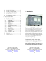
MAC-200
Master Antenna Controller
User Manual
Thank you for buying your new MAC-200 Master
Antenna Controller. The MAC-200 incorporates the
very latest American-made technology as well as our
experience in having delivered more than 100,000
Smartuners since 1985. It is a state-of-the-art tuner
providing a new and unique level of usefulness.
The concept of the MAC-200 is quite different from
our line of Smartuners. Instead of dedicating one
Smartuner per antenna, we’ve brought the tuner to
the point where all of the antennas come together:
the radio room. The MAC-200 provides tuning for
all antennas in a single box. The ease of installation
and flexible operation make this an ideal choice. We
know that the simplicity, reliability, and flexibility
of the MAC-200 will enhance your HF operation for
years to come.
SGC continues to focus on providing the most useful
products and services for our customers around the
world. Please feel free to call to discuss your antenna
system requirements at any time. We look forward
to making your HF experience the very best.
Downloaded by
Amateur Radio Directory
Cat. # XX-XX
Pierre Goral
President, SGC Inc.
www.hamdirectory.info
August 2003
Mailing: PO Box 3526, Bellevue, WA. 98009
Shipping: 13737 SE 26th St. Bellevue, WA. 98005
Toll Free: 800-259-7331 * Phone: 425-746-6310 * Fax: 425-746-6384
www.sgcworld.com * Email: [email protected]
2
NOTICES
Table of Contents
READING THIS MANUAL: The most important sections to
read in this manual are MAC-200 SETUP (section XX) and
MAC-200 OPERATION (section XX). All users should read
and understand this material. Other information such as
Theory of Operation is provided for those who want to
understand their new MAC-200 more completely.
1
INTRODUCTION ...............................................................6
2
TECHNICAL SPECIFICATIONS ....................................8
3
MAC-200 SETUP ................................................................9
3.1
MECHANICAL DESIGN ..................................................9
3.1.1
Opening the MAC-200............................... 9
3.2
CONNECTIONS TO THE MAC-200 ................................12
3.2.1
12 VDC Power .........................................12
3.2.2
RF Input from your transceiver .................14
3.2.3
Chassis Ground .......................................14
3.2.4
Connecting Antennas to the MAC-200......15
3.3
ANTENNAS AND THE MAC-200 ..................................19
3.3.1
Optimum Coupling....................................19
3.3.2
Connecting Multiple Antennas ..................20
3.3.3
Balanced vs. Unbalanced Antennas .........21
3.3.4
Antennas with Feed Point Tuning .............22
3.3.5
Antenna Recommendations .....................22
3.3.6
Tips & Tricks ............................................32
3.3.7
References on Antennas ..........................33
3.4
THE GOLDEN RULES OF HF INSTALLATION ................34
ATTENTION: The MAC-200 RF Path is interrupted when
power is off in both receive and transmit modes. To prevent
damage to transceivers, do not operate with power off to this
device.
NOTE: For efficient operation of the MAC-200, apply 12
VDC from the same power supply as the transceiver.
4
MAC-200 OPERATION ...................................................36
4.1
POWERING ON THE MAC200 .......................................36
4.1.1
Backlighting..............................................36
4.1.2
Keytones..................................................37
Mailing: PO Box 3526, Bellevue, WA. 98009
Shipping: 13737 SE 26th St. Bellevue, WA. 98005
Toll Free: 800-259-7331 * Phone: 425-746-6310 * Fax: 425-746-6384
www.sgcworld.com * Email: [email protected]
Mailing: PO Box 3526, Bellevue, WA. 98009
Shipping: 13737 SE 26th St. Bellevue, WA. 98005
Toll Free: 800-259-7331 * Phone: 425-746-6310 * Fax: 425-746-6384
www.sgcworld.com * Email: [email protected]
3
4
4.2
4.3
4.4
4.5
4.6
5
SELECTING THE METER RANGE ..................................38
SELECTING THE OPERATING ANTENNA ........................38
AUTO VS. MANUAL ANTENNA SELECTION .................39
FRONT PANEL RESET-LOCK OPERATION .....................41
DO-IT-YOURSELF LIGHT BULB TEST ..........................42
1 Introduction
THEORY OF OPERATION ............................................46
5.1
TUNING PROCESS AND OPTIONS .................................47
5.1.1
Tuning Process ........................................48
5.1.2
Impedance Detector .................................49
5.1.3
VSWR Detector........................................50
5.1.4
Phase Detector ........................................51
5.1.5
Central Processing Unit (CPU) .................53
5.1.6
Initialization ..............................................54
5.1.7
Jumper Settings .......................................55
5.1.8
Program Description.................................56
5.1.9
Tuning Paths............................................59
5.1.10
Internal B.I.T.E.* LEDs .............................64
5.2
SCHEMATICS ...............................................................67
5.3
COMPONENT LOCATION..............................................68
Why did we create the MAC-200? To pull together the essential
tools for antenna management for stations with more than one
antenna. Discussions with amateurs and professionals have shown
that most have more than one antenna that they need to deal with,
yet the only place where all of these antennas come together is in
the radio room. Only there is it possible to manage which antenna
is in use and provide matching for all of them. Unfortunately,
existing tools just don’t go far enough.
From antenna switches, to complex, electronic, computer
controlled antenna switches … the only thing available has been a
switch. Existing devices allow directing RF to one antenna or
another from a group of antennas. Some manual tuners provide for
two or sometimes three antennas with an ability to tune them, but
Mailing: PO Box 3526, Bellevue, WA. 98009
Shipping: 13737 SE 26th St. Bellevue, WA. 98005
Toll Free: 800-259-7331 * Phone: 425-746-6310 * Fax: 425-746-6384
www.sgcworld.com * Email: [email protected]
Mailing: PO Box 3526, Bellevue, WA. 98009
Shipping: 13737 SE 26th St. Bellevue, WA. 98005
Toll Free: 800-259-7331 * Phone: 425-746-6310 * Fax: 425-746-6384
www.sgcworld.com * Email: [email protected]
5
6
now SGC has taken the next step and added an intelligent tuner to
the control station.
The MAC-200 is something completely new, an antenna switching
system that also provides built in intelligent tuning capability to
trim the line before going into your transceiver. The MAC-200 has
170 built in memories to remember both the tuning parameters and
the antenna at a variety of frequencies. It has all of the
sophistication developed over the years with SGC’s Smartuner line
of antenna couplers. However, the MAC-200 is an antenna
TUNER intended for installation near the transceiver rather than at
the antenna feed point..
The MAC-200, located as it is in the radio room at the point where
all antenna feed lines come together, provides tuning at the end of
the antenna feed line rather than at the optimum point, the antenna
feed point. SGC Smartuners provide for matching of an antenna to
the feed line, thereby minimizing SWR and losses on the line. The
MAC-200 allows control of multiple antennas from a single box
and tuning the antenna system in order to connect to the
transceiver, but it must match the impedance as reflected by the
transmission line to the device.
Downloaded by
Amateur Radio Directory
www.hamdirectory.info
2 Technical Specifications
HF Frequency Range
Power Input
Number of Inputs
Revolving Memory Bins
Number of Outputs
Network
Impedance Range
Longwire
feedline
Balanced Output
VSWR
DC Input Requirement
DC Operating Range
Input Current
Random Set Time
Recurrent Set Time
Antenna Length (Long Wire)
Installation
Operating Temperature
Size
Weight
Case Construction
Meters
Cable Connections
1.8-60Mhz
1.5-200 watts PEP
1 type SO239
168
5 – 1 End Fed, 1 Balanced Feed, 3
Coaxial
Pi Configuration
.2-5000 ohms
5-1000 ohms
5-1000 ohms
Typically less than 2:1
+13.8 VDC (nominal)
+10 to 18.5VDC
230 milliamps average
Typically < 2 seconds
Typically < 10 ms
Minimum 9 ft – 7-30Mhz
Minimum 40 ft - 3-30Mhz
Minimum 100 ft – 1.8-30Mhz
Desktop
-35 to +70C
6.5 X 3 X 8.5 inches
5 pounds
Extruded Aluminum
1 SWR
1 Power with 20 & 200 watt scales
Standard Coaxial PLUS
Standard mini-plug for DC PLUS
Lugs for wire antennas and ground
Mailing: PO Box 3526, Bellevue, WA. 98009
Shipping: 13737 SE 26th St. Bellevue, WA. 98005
Toll Free: 800-259-7331 * Phone: 425-746-6310 * Fax: 425-746-6384
www.sgcworld.com * Email: [email protected]
Mailing: PO Box 3526, Bellevue, WA. 98009
Shipping: 13737 SE 26th St. Bellevue, WA. 98005
Toll Free: 800-259-7331 * Phone: 425-746-6310 * Fax: 425-746-6384
www.sgcworld.com * Email: [email protected]
7
8
In order to open the MAC-200 to get at
the JP1 or JP3 jumpers or to visually
inspect the circuit boards, you need to
do the following:
3 MAC-200 Setup
3.1 Mechanical Design
The MAC-200 is in an aluminum case. RF and DC power come
through the back of the case. Internal construction is normal for
fixed location use. Corrosion-resistant hardware and passive alloys
are used throughout. For 99% of installations, the factory settings
for the internal jumpers will be correct.
1.
Loosen the cover lock on the
back panel of the MAC-200
until the washer disengages
from the MAC-200 cover.
2.
Slide the cover forwards or
backwards until it disengages
from the rail.
3.1.1 Opening the MAC-200
The MAC-200 cover is locked in place with
a simple arrangement using an oversized
washer to engage a small groove in the side
of the cover to prevent its movement. A #4
screw and a slightly oversized washer (#6 or
#8) are locked in place by a lock washer to
prevent movement of the cover.
Mailing: PO Box 3526, Bellevue, WA. 98009
Shipping: 13737 SE 26th St. Bellevue, WA. 98005
Toll Free: 800-259-7331 * Phone: 425-746-6310 * Fax: 425-746-6384
www.sgcworld.com * Email: [email protected]
Mailing: PO Box 3526, Bellevue, WA. 98009
Shipping: 13737 SE 26th St. Bellevue, WA. 98005
Toll Free: 800-259-7331 * Phone: 425-746-6310 * Fax: 425-746-6384
www.sgcworld.com * Email: [email protected]
9
10
To re-close the cover:
1.
2.
3.
Orient the cover so
that the small groove
for the locking washer
is at the back of the
MAC-200
Engage the cover with
the body of the MAC200 from the front or
the back and slide it
into place.
Holding the MAC-200 with the back panel UP, push
the washer into the slot engaging the cover slot. Place
the locking washer over this, and drive the screw into
the hole until tight.
3.2 Connections to the Mac-200
All connections to the MAC-200 are made on the back panel.
NOTE: Under normal operating conditions, it is good practice to
connect a dummy load to one of the 50-Ohm antenna connectors in
order to have it available for test purposes.
3.2.1 12 VDC Power
ATTENTION: The MAC-200 RF Path is interrupted when
power is off in both receive and transmit modes. To prevent
damage to transceivers, do not operate with power off to this
device.
NOTE: For efficient operation of the MAC-200, apply 12
VDC from the same power supply as the transceiver.
Mailing: PO Box 3526, Bellevue, WA. 98009
Shipping: 13737 SE 26th St. Bellevue, WA. 98005
Toll Free: 800-259-7331 * Phone: 425-746-6310 * Fax: 425-746-6384
www.sgcworld.com * Email: [email protected]
Mailing: PO Box 3526, Bellevue, WA. 98009
Shipping: 13737 SE 26th St. Bellevue, WA. 98005
Toll Free: 800-259-7331 * Phone: 425-746-6310 * Fax: 425-746-6384
www.sgcworld.com * Email: [email protected]
11
12
3.2.2 RF Input from your transceiver
Chassis
Ground
A standard SO-239 jack is for RF Input from your transceiver.
3.2.3 Chassis Ground
12 VDC
Connection
RF Input
The chassis ground should be connected to a suitable station safety
grounding system.
The MAC-200 has a miniature power input jack on the back panel.
Any voltage from 10 to 18.5 VDC is suitable for operation of the
MAC-200. Average current draw will be approximately 230
milliamps. The MAC-200 should be powered from the same power
supply used to supply your transceiver to ensure that it is energized
whenever the transceiver is in operation.
Mailing: PO Box 3526, Bellevue, WA. 98009
Shipping: 13737 SE 26th St. Bellevue, WA. 98005
Toll Free: 800-259-7331 * Phone: 425-746-6310 * Fax: 425-746-6384
www.sgcworld.com * Email: [email protected]
Mailing: PO Box 3526, Bellevue, WA. 98009
Shipping: 13737 SE 26th St. Bellevue, WA. 98005
Toll Free: 800-259-7331 * Phone: 425-746-6310 * Fax: 425-746-6384
www.sgcworld.com * Email: [email protected]
13
14
3.2.4 Connecting Antennas to the MAC-200
3.2.4.2 Long Wire Connections
3.2.4.1 Coax antenna feeds
Long Wire (unbalanced)
RF Hot Connection
SO-239
Connectors
for Coaxial
Cable
Three SO-239 connectors are provided for antennas fed with
Coaxial cable. SGC recommends that one connector be reserved
for a dummy load if possible for testing purposes. From the front
panel, these three connections correspond to switches 3, 4, and 5.
Long Wire (unbalanced)
RF Ground Connection
The long wire connection starts from two lugs on the back panel
labeled ‘Longwire.’ They correspond to antenna selection switch 2
on the front panel. An RF ground connects to the lug labeled RF
GND. This wire should be 5-10% longer than the random length
long wire.
Mailing: PO Box 3526, Bellevue, WA. 98009
Shipping: 13737 SE 26th St. Bellevue, WA. 98005
Toll Free: 800-259-7331 * Phone: 425-746-6310 * Fax: 425-746-6384
www.sgcworld.com * Email: [email protected]
Mailing: PO Box 3526, Bellevue, WA. 98009
Shipping: 13737 SE 26th St. Bellevue, WA. 98005
Toll Free: 800-259-7331 * Phone: 425-746-6310 * Fax: 425-746-6384
www.sgcworld.com * Email: [email protected]
15
16
IMPORTANT NOTE: A long wire connected at the back of the
MAC-200 will be radiating from the moment is leaves the MAC200. This can lead to excessive RF levels within the radio room at
even modest power levels. The length of wire within the radio
room needs to be kept short.
3.2.4.3 Balanced Feed Connections
3.2.4.4 Multiple Antenna Connections
The MAC-200 was designed specifically to allow multiple antenna
types with multiple antennas feed lines to be controlled from a
single location. Up to five different antennas can be connected,
three fed by coaxial lines, one with an unbalanced line, and one
with a balanced line. All of these are switch selectable from the
front panel.
Balanced
Feed Line
Connection
The balanced feed connections corresponding to antenna switch 1,
will accept any form of balanced feed line for an external antenna.
Mailing: PO Box 3526, Bellevue, WA. 98009
Shipping: 13737 SE 26th St. Bellevue, WA. 98005
Toll Free: 800-259-7331 * Phone: 425-746-6310 * Fax: 425-746-6384
www.sgcworld.com * Email: [email protected]
Mailing: PO Box 3526, Bellevue, WA. 98009
Shipping: 13737 SE 26th St. Bellevue, WA. 98005
Toll Free: 800-259-7331 * Phone: 425-746-6310 * Fax: 425-746-6384
www.sgcworld.com * Email: [email protected]
17
18
3.3 Antennas and the MAC-200
The MAC-200 can accommodate a wide variety of antennas
providing a convenient way to switch between them and to tune
them, all in the same box.
This is a compromise location. The optimum location is the
antenna feed point where the impedance match keeps SWR on the
feed line to an absolute minimum.
3.3.2 Connecting Multiple Antennas
The MAC-200 is provided with 3 SO-239 connectors, one RFHot/RF-GND pair, and one balanced feed connection. The SO-239
connectors are intended to connect to a normal Coaxial feedline.
Any antenna that is properly setup for Coax feed can be connected
to one of these connectors..
One common benefit of having a
switch able antenna controller is
the ability to leave a dummy load
connected so that you can switch to
it conveniently at need.
The RF Hot/RF GND connections
feed a long or random wire
antenna. They can feed any unbalanced antenna with RF Hot
connected to the radiator and RF GND to the RF Grounding
system.
3.3.1 Optimum Coupling
The MAC-200 incorporates a coupler internally to provide for
tuning on a variety of antennas under direct control of the user.
Mailing: PO Box 3526, Bellevue, WA. 98009
Shipping: 13737 SE 26th St. Bellevue, WA. 98005
Toll Free: 800-259-7331 * Phone: 425-746-6310 * Fax: 425-746-6384
www.sgcworld.com * Email: [email protected]
Mailing: PO Box 3526, Bellevue, WA. 98009
Shipping: 13737 SE 26th St. Bellevue, WA. 98005
Toll Free: 800-259-7331 * Phone: 425-746-6310 * Fax: 425-746-6384
www.sgcworld.com * Email: [email protected]
19
20
unbalanced antennas are long wires and verticals.
IMPORTANT NOTE: The RF-Hot connection will radiate RF
from any wire connected to it. Not only is this an RF Hazard
within the station, but it can cause local interference both within
the station and in the vicinity depending on your power level.
The balanced feed connection is for a ladder line feed connecting
to a balanced antenna like a dipole or a loop.
3.3.3 Balanced vs. Unbalanced Antennas
An important distinction is between
balanced and unbalanced antennas.
Balanced antennas are electrically balanced
at the feed point. Typical balanced antennas
are dipoles and loops.
Unbalanced antennas need an RF
Ground or counterpoise to create
electrical balance and depend on the
quality of the ground for a high quality
radiated signal. Without a good quality
ground, unbalanced antennas will cause
interference, lead to RF in the radio
room, and be of very low efficiency due
to high losses in the ground. Typical
3.3.4 Antennas with Feed Point Tuning
An antenna with a feed point tuner, such as an SGC Smartuner,
will work compatibly with the MAC-200. You can either leave the
MAC-200 to tune as it needs to or cut out the tuning function by
doing the following:
•
•
•
•
Select the antenna
Push the MANUAL button to disengage automatic tuning
Press RESET to reset the coupler to bypass mode
Push the LOCK button to lock the coupler.
3.3.5 Antenna Recommendations
There are many ways to connect antennas for use. Here are some
common examples that can help you get started with your MAC200. For additional information about antennas, we recommend
that you obtain a copy of our HF User’s Guide from our website at
XXXXXX. For detailed technical information about antennas, the
consistently best source is the ARRL Antenna Handbook.
Mailing: PO Box 3526, Bellevue, WA. 98009
Shipping: 13737 SE 26th St. Bellevue, WA. 98005
Toll Free: 800-259-7331 * Phone: 425-746-6310 * Fax: 425-746-6384
www.sgcworld.com * Email: [email protected]
Mailing: PO Box 3526, Bellevue, WA. 98009
Shipping: 13737 SE 26th St. Bellevue, WA. 98005
Toll Free: 800-259-7331 * Phone: 425-746-6310 * Fax: 425-746-6384
www.sgcworld.com * Email: [email protected]
21
22
Stealthy
antennas are
built in a
variety of
ways. A
simple
example is a
roofmounted
dipole with
3.3.5.1 Dipoles
Balanced antennas
can be connected to
the balanced line
connections on the
back of the MAC200.
its ends bent 90 degrees and fed from the MAC-200.
3.3.5.2 The Inverted V Antenna
Some balanced
antennas, such as the
doublet, have a coax
feed at the center
point. Simply connect
your coax feed line to
the MAC-200 at
connectors 1, 2, or 3.
The inverted-V antenna can
be fed with ladder line run
from the balanced line
connection on the MAC200, but it is also commonly
fed from coaxial cable with
the center conductor to one
side and the shield to the
other.
Mailing: PO Box 3526, Bellevue, WA. 98009
Shipping: 13737 SE 26th St. Bellevue, WA. 98005
Toll Free: 800-259-7331 * Phone: 425-746-6310 * Fax: 425-746-6384
www.sgcworld.com * Email: [email protected]
Mailing: PO Box 3526, Bellevue, WA. 98009
Shipping: 13737 SE 26th St. Bellevue, WA. 98005
Toll Free: 800-259-7331 * Phone: 425-746-6310 * Fax: 425-746-6384
www.sgcworld.com * Email: [email protected]
23
24
3.3.5.3 Dipoles with Matching Lines
Some antennas, such as
the G5RV, use a section
of ladder line as a
matching device. These
transform the impedance
of feed point to
something near 50
ohms. Usually, the
ladder line terminates in
a 1:1 balun. The Coaxial
line from the transceiver connects to the balun. The MAC-200 can
feed this connection directly from one of the coax ports or you can
remove the balun run the ladder line directly to the MAC-200
balanced feed line port.
3.3.5.4 Long Wires & Inverted Ls
Long wire and
inverted L antennas
are unbalanced
antennas. They are
fed from the upper
LONGWIRE
connection directly
with a single wire.
CAUTION: Unbalanced antennas are radiating from the line as
soon as they leave the MAC-200. Minimize the amount of wire
inside the radio room to prevent interference with electronic
equipment. Minimizing power will also minimize interference
caused by this kind of antenna.
Mailing: PO Box 3526, Bellevue, WA. 98009
Shipping: 13737 SE 26th St. Bellevue, WA. 98005
Toll Free: 800-259-7331 * Phone: 425-746-6310 * Fax: 425-746-6384
www.sgcworld.com * Email: [email protected]
Mailing: PO Box 3526, Bellevue, WA. 98009
Shipping: 13737 SE 26th St. Bellevue, WA. 98005
Toll Free: 800-259-7331 * Phone: 425-746-6310 * Fax: 425-746-6384
www.sgcworld.com * Email: [email protected]
25
26
may be incorporated into the design of the antenna itself.
More than any other
factor, a good RF
ground will help to
improve the radiated
signal from these
antennas and
minimize RFI
generated by the
antenna.
As a minimum, an RF
Ground can consist of
a wire 5-10% longer than the wire antenna and laid out so that it
does not cross over itself or form a loop. A far better RF ground
can be constructed by adding ground radials radiating from a
suitable point and connected to the RF GND lug on connector 2 of
the MAC-200.
3.3.5.5 Vertical Antennas
A vertical antenna may be
connected to the MAC-200
in a number of ways. Most
vertical antennas will require
an RF Ground system to
function properly, but this
A typical vertical antenna is the GROUND PLANE design that
incorporates radials within the design. This, and may other vertical
antennas use an SO-239 connector or equivalent to feed the
antenna. This type of antenna should be connected to one of the
three SO-239 connectors on the MAC-200 (switches 1, 2, or 3).
Any vertical antenna fed with Coaxial cable can be connected in
this way.
Home made vertical
antennas are commonly
made in one of two
ways. A very common
type of construction
builds the radial system
at the base of the
antenna. Flag pole
antennas are normally
built in this way. Coax
line can be run from the
MAC-200 to the base of the antenna. The center lead of the coax
will feed the radiating element in the flagpole vertical while the
coax shield will be connected to the RF grounding system.
Another way that a vertical can be fed is to have it fed with a wire
directly from the MAC-200 with the RF grounding system also
connected directly to the MAC-200. In this case, the vertical will
Mailing: PO Box 3526, Bellevue, WA. 98009
Shipping: 13737 SE 26th St. Bellevue, WA. 98005
Toll Free: 800-259-7331 * Phone: 425-746-6310 * Fax: 425-746-6384
www.sgcworld.com * Email: [email protected]
Mailing: PO Box 3526, Bellevue, WA. 98009
Shipping: 13737 SE 26th St. Bellevue, WA. 98005
Toll Free: 800-259-7331 * Phone: 425-746-6310 * Fax: 425-746-6384
www.sgcworld.com * Email: [email protected]
27
28
be connected exactly like a long wire antenna to the LONGWIRE
lugs with the vertical element connected to the top lug and the RF
Grounding system connected to the RF GND connector. This
configuration could be a very poor radiator unless the feed line is
elevated from the ground. The feed wire in this case will be part of
the RF radiating system.
Loops can be
conveniently arranged
either horizontally or
vertically, but the
feeding arrangement
from the MAC-200
would be the same.
3.3.5.6 Loops
Loop antennas are balanced
antennas that are very simple to
feed from a balanced feed line.
Ideally, a Smartuner would be at
the loop feed point, but when
using the MAC-200, balanced
feedline will minimize SWR
between the MAC-200 and the
loop. A loop would typically be
connected to the MAC-200 at the
BALANCED connection (switch position 1).
Mailing: PO Box 3526, Bellevue, WA. 98009
Shipping: 13737 SE 26th St. Bellevue, WA. 98005
Toll Free: 800-259-7331 * Phone: 425-746-6310 * Fax: 425-746-6384
www.sgcworld.com * Email: [email protected]
Mailing: PO Box 3526, Bellevue, WA. 98009
Shipping: 13737 SE 26th St. Bellevue, WA. 98005
Toll Free: 800-259-7331 * Phone: 425-746-6310 * Fax: 425-746-6384
www.sgcworld.com * Email: [email protected]
29
30
Loops can take on
nearly any closed shape
such as a square,
rectangle, triangle, or
diamond shape and they
can be fed on the sides
or in the corners. The
impact of different
configurations and feed
points is well
documented in the many
3.3.6 Tips & Tricks
1.
The most frequent source of problems in unbalanced
antenna systems is the RF Ground. RF grounding is
frequently misunderstood and poorly implemented. See
our book The HF User’s Guide available free for
download from [WEB ADDRESS].
2.
Be aware of the difference between a SAFETY ground
and an RF ground. Safety grounding is necessary to
protect your life and property from coming into contact
with lethal doses of electricity. RF grounds, when
required, are necessary to the operation of your antenna
system. Connecting the two together can inject RF into
your other electronic equipment.
3.
It is a good idea to reserve one SO-239 position on the
MAC-200 for a dummy load suitable for initial tune-up
on your transceiver.
4.
Plan your antenna installation carefully!
5.
Don’t commit to a final installation until you have tried
out your antennas in as near to final form as possible.
books on antennas.
It is also possible to feed a loop from a Coax connection by
connecting one side of the feed point to the center conductor and
the other side of the feed point to the coax shield.
3.3.5.7 Beams
Typically, the radiating
element of a beam is a
dipole antenna fed with
coaxial cable. Connecting a
beam to the MAC-200 is
accomplished by connecting
the coax to positions 3, 4, or
5.
Mailing: PO Box 3526, Bellevue, WA. 98009
Shipping: 13737 SE 26th St. Bellevue, WA. 98005
Toll Free: 800-259-7331 * Phone: 425-746-6310 * Fax: 425-746-6384
www.sgcworld.com * Email: [email protected]
Mailing: PO Box 3526, Bellevue, WA. 98009
Shipping: 13737 SE 26th St. Bellevue, WA. 98005
Toll Free: 800-259-7331 * Phone: 425-746-6310 * Fax: 425-746-6384
www.sgcworld.com * Email: [email protected]
31
32
3.3.7 References on Antennas
3.4 The Golden Rules of HF Installation
3.3.7.1 From SGC
These rules apply to all types of stations, including base, mobile,
air-borne and marine. They are very important for planning and
installing your HF system, if you want to achieve good
communications.
SGC, HF User’s Guide, available free from
http://www.sgcworld.com/ftp/Books/hfguide.pdf
SGC, Stealth Antenna Manual, available free from
http://www.sgcworld.com/ftp/Books/STEALTHman.pdf
1.
2.
3.3.7.2 Books
Carr, Joseph, Practical Antenna Handbook, 3rd Edition, McGrawHill, New York, 1998.
Hale, Bruce, Editor, The ARRL Handbook, ARRL, Newington,
Ct., 1988.
Hall, Gerald, Editor, The ARRL Antenna Book, ARRL,
Newington, Ct., 1991
Hare, Ed and Schelgen, Robert, Editors, Radio Frequency
Interference: How to Find It and Fix It, ARRL, Newington, Ct.,
1991.
Kleinschmidt, Kirk, Stealth Amateur Radio, ARRL, Newington,
Ct., 2001.
3.
4.
5.
Install transceiver as close to operation site and
power supply system as possible (whether it is an
external power supply or battery system).
The antenna must be installed in an open space and
as far as possible from your operating point.
Example: on a sailboat use the backstay as the
antenna, since it is the farthest point away from the
rest of the vessel.
The antenna coupler must be installed at the base of
the antenna.
Always create your own ground with radial wire or
copper straps. They are the only ones that will
guarantee a solid and proper ground system.
All cables - power supply, control or coaxial - must
always be as short as possible and/or necessary. Any
excess cable should be shortened to the proper length
- never coiled.
Following these rules will minimize marginal installations and
problem sources such as RF feedback in the radio, power supply or
cables and “hot” or RF burning microphones. If all 5 above points
Mailing: PO Box 3526, Bellevue, WA. 98009
Shipping: 13737 SE 26th St. Bellevue, WA. 98005
Toll Free: 800-259-7331 * Phone: 425-746-6310 * Fax: 425-746-6384
www.sgcworld.com * Email: [email protected]
Mailing: PO Box 3526, Bellevue, WA. 98009
Shipping: 13737 SE 26th St. Bellevue, WA. 98005
Toll Free: 800-259-7331 * Phone: 425-746-6310 * Fax: 425-746-6384
www.sgcworld.com * Email: [email protected]
33
34
are followed during the design and installation of your HF system,
the operator can expect top performance. Further information
regarding applications, installation and operation can be
downloaded from our website www.sgcworld.com. These
publications include:
•
•
•
•
4 MAC-200 Operation
4.1 Powering on the Mac200
HF User’s Guide
Go Mobile at 500 Watts
Stealth Antennas
Smartuner Antenna Coupler Manuals
Power Button
Momentarily press the Red Power button on the front panel to
activate the MAC-200. You should see the LEDs behind the meter
displays light up.
4.1.1 Backlighting
During power on, the MAC-200 checks to see if the AUTO or
MANUAL keys are pressed. If the AUTO key is pressed, meter
Mailing: PO Box 3526, Bellevue, WA. 98009
Shipping: 13737 SE 26th St. Bellevue, WA. 98005
Toll Free: 800-259-7331 * Phone: 425-746-6310 * Fax: 425-746-6384
www.sgcworld.com * Email: [email protected]
Mailing: PO Box 3526, Bellevue, WA. 98009
Shipping: 13737 SE 26th St. Bellevue, WA. 98005
Toll Free: 800-259-7331 * Phone: 425-746-6310 * Fax: 425-746-6384
www.sgcworld.com * Email: [email protected]
35
36
backlighting is turned ON. If the MANUAL key is pressed, meter
backlighting is turned OFF. Default from the factory is
backlighting ON. The current backlighting settings are stored and
will be recovered whenever the MAC-200 is started.
4.2 Selecting the Meter Range
Backlighting can be turned on or off by pressing the RESET button
and holding the AUTO or MANUAL key during microprocessor
reset.
Meter Range
Selection
4.1.2 Keytones
During power on, the MAC-200 checks to see if the 20W or 200W
keys are pressed. If the 20W key is pressed, keytones are turned
ON. If the 200W key is pressed, keytones are turned OFF. Default
from the factory is keytones ON. The current keytones settings are
stored and will be recovered whenever the MAC-200 is started.
Keytones can be turned on or off by pressing the RESET button
and holding the 20W or 200W key during microprocessor reset.
The meter range selection is made on the two push button switches
to the left of the meters. Press the switch labeled 20W to activate a
20 watt range. Press the switch labeled 200W to activate the 200
watt range. No harm will come to the meters if the wrong range is
activated for the power applied. When a given range is selected, a
small LED will light above the switch to indicate which range is
currently selected.
4.3 Selecting the operating antenna
To select an antenna, push the number antenna switch on the front
panel shortly. A small LED above the switch lights to indicate that
it is selected. The selections are:
Mailing: PO Box 3526, Bellevue, WA. 98009
Shipping: 13737 SE 26th St. Bellevue, WA. 98005
Toll Free: 800-259-7331 * Phone: 425-746-6310 * Fax: 425-746-6384
www.sgcworld.com * Email: [email protected]
Mailing: PO Box 3526, Bellevue, WA. 98009
Shipping: 13737 SE 26th St. Bellevue, WA. 98005
Toll Free: 800-259-7331 * Phone: 425-746-6310 * Fax: 425-746-6384
www.sgcworld.com * Email: [email protected]
37
38
Switch Number
1
2
3
4
5
Antenna
Balanced Antenna
Long Wire Antenna
Coax 3
Coax 4
Coax 5
In the AUTO mode operation the MAC-200 remembers not only
the frequency, but the antenna. The tuner will save the selected
antenna along with the tuner settings when a successful match is
found. Both the tuner settings and the antenna settings will be
recalled the next time the MAC-200 is operated at that frequency.
Antenna settings are kept in a special set of bins. Only one antenna
may be stored in each bin. The upper frequency limit on each bin is
given in the table below:
Freq (Mhz)
2.816
5.376
8.704
12.032
16.128
19.712
23.040
26.368
39.936
4.4 Auto vs. Manual Antenna Selection
The AUTO and MANUAL buttons control the operation of the
microprocessor in selecting an antenna. A small LED over each
switch indicates the current operating mode.
When changing the selected antenna in AUTO mode, the LED
above the AUTO switch will blink for 10 seconds after a new
antenna is selected. Transmitting while the LED is blinking will
cause the MAC-200 to store the antenna selection in the
appropriate bin. If no transmission occurs while the LED is
blinking, the MAC-200 will go back to its stored antenna.
Mailing: PO Box 3526, Bellevue, WA. 98009
Shipping: 13737 SE 26th St. Bellevue, WA. 98005
Toll Free: 800-259-7331 * Phone: 425-746-6310 * Fax: 425-746-6384
www.sgcworld.com * Email: [email protected]
Mailing: PO Box 3526, Bellevue, WA. 98009
Shipping: 13737 SE 26th St. Bellevue, WA. 98005
Toll Free: 800-259-7331 * Phone: 425-746-6310 * Fax: 425-746-6384
www.sgcworld.com * Email: [email protected]
39
40
When operating in MANUAL mode, the MAC-200 ignores the
antenna setting, but the antenna tuner continues to function. Tuner
settings will be stored and recalled from memory without changing
the antenna selection setting. This may cause retuning when going
back to the AUTO mode since the antenna and the tuning settings
may no loner match.
Tuner settings are stored in predefined ‘bins’ across the range of
the tuner. The width of each bin varies with frequency, but
averages approximately 170 kHz per bin, with more bins at lower
frequencies and fewer, wider bins at higher frequencies. Retuning
may occur when working at opposite ends of a bin if the change in
feed point impedance with frequency is particularly high. This will
be particularly common with High-Q, narrow bandwidth antennas.
4.5 Front Panel Reset-Lock operation
The LOCK button when engaged (the small LED next to the
button is on), tells the coupler to ignore all instructions to tune. It
will not react to a change in any sensor. The RESET function,
when pressed, resets all internal relays to a position that connects
the transceiver directly to the antenna.
4.6 Do-it-Yourself Light Bulb Test
Any time that a transmitter is used, it must be outputting into a
load. A load is anything that the output power can be pumped into.
If the transmitter is operated without any sort of load connected,
the final amplifier stage could become severely damaged. The
problem is that you should never test a transmitter on the air for the
first time, if you are unsure about how to operate it, and if you are
unsure whether it is working properly. You could create harmful
interference to other stations.
To test transmitters without actually operating into an antenna,
dummy loads were created. A dummy load is a load that will
dissipate the energy from the transmitter instead of emanating it
into the ionosphere. Nearly all commercial dummy loads are large
oil-filled cans. These dummy loads change the transmitted energy
into heat, which is absorbed by the oil. Because different
transmitters output different amounts of power, different sizes of
dummy loads must be used. Dummy loads for typical amateur
powers (<500 watts) are relatively inexpensive and are readily
available.
Unfortunately, when you use a can-type dummy load, you can’t
see “what’s happening” with your transmitter. In this case, you can
use a light-bulb dummy load to test your transmitter. Here, the
light bulb is directly connected to the output of the transmitter and
it dissipates the RF energy as light. The light bulb dummy load is
more useful than the oil-can type because you can guess how much
Mailing: PO Box 3526, Bellevue, WA. 98009
Shipping: 13737 SE 26th St. Bellevue, WA. 98005
Toll Free: 800-259-7331 * Phone: 425-746-6310 * Fax: 425-746-6384
www.sgcworld.com * Email: [email protected]
Mailing: PO Box 3526, Bellevue, WA. 98009
Shipping: 13737 SE 26th St. Bellevue, WA. 98005
Toll Free: 800-259-7331 * Phone: 425-746-6310 * Fax: 425-746-6384
www.sgcworld.com * Email: [email protected]
41
42
power is being output, you can see the voice modulate the SSB
(the light will flicker with your voice peaks), and you can tune the
transmitter for maximum out-put (if the transmitter is an older
model that requires tuning).
Before building or using the light-bulb dummy load, remember
that these models typically don’t dissipate the transmitter’s output
as well as an oilcan dummy load. The result is that RF will “leak”
out; we have heard a few stories of amateurs who were heard
around town while operating their transmitters into a light-bulb
dummy load. If you use this system, make sure that you test the
equipment on a clear, harmless frequency (NEVER test with the
transmitter set on an emergency frequency, such as 2182 KHz).
SGC recommends that you build the light-bulb dummy load with
the following parts although we have made one with an old light
fixture and a makeshift version with just alligator clip leads and a
light bulb):
•
•
•
•
•
•
AC socket to cable with a PL-259 connector (for
transceiver)
AC socket to cable with alligator clips (needed with
coupler)
Light bulb to AC adapter
75 to 125 watt light bulb, 120 to 220 VAC
100 watt radio transceiver
Any SGC Smartuner or equivalent
ATTENTION: Some retuning may take place as the impedance of the light bulb
varies with the power level. If the power level is held constant with a continuous
carrier such as produced by CW mode operation, the coupler setting will settle after
a short period of time.
RADIO TEST PROCEDURE
1.
2.
3.
4.
Connect the transceiver light bulb load to the radio
RF in/out jack.
Turn on the radio and set the CW mode.
Key the PTT switch on the microphone and look at
the light bulb. If the light bulb load is connected and
the radio is transmitting, the light should turn on.
Set the radio to SSB mode.
Mailing: PO Box 3526, Bellevue, WA. 98009
Shipping: 13737 SE 26th St. Bellevue, WA. 98005
Toll Free: 800-259-7331 * Phone: 425-746-6310 * Fax: 425-746-6384
www.sgcworld.com * Email: [email protected]
Mailing: PO Box 3526, Bellevue, WA. 98009
Shipping: 13737 SE 26th St. Bellevue, WA. 98005
Toll Free: 800-259-7331 * Phone: 425-746-6310 * Fax: 425-746-6384
www.sgcworld.com * Email: [email protected]
43
44
5.
Key the PTT switch on the microphone and talk into
the microphone. Notice that the light turns on when
you talk.
COUPLER TEST PROCEDURE
1.
2.
3.
4.
5.
6.
Connect the coupler to the radio.
Connect coupler light bulb load to Smartuner coupler antenna
out-put.
Turn on the radio and the Smartuner coupler.
Set the radio to the CW mode.
Key the PTT switch on the microphone and look at the light
bulb. The light should turn on if the coupler has completed its’
tuning cycle and if the radio is transmitting.
For further testing, follow steps 4 & 5 of the radio test
procedure. Note: The light bulb might not turn on immediately
if the coupler has not yet been tuned for the frequency of the
transmitter. The output power (light-bulb brightness) is
greatest when the coupler is properly tuned. This test will
ensure that the radio and coupler are working properly.
5 Theory of Operation
The MAC-200 tuner is built around two basic coupler networks,
the L & PI. Note that the L network as viewed from the transceiver
may be configured as either “C in” or “C out,” whichever is
required by the load. In either case, the end of the network
containing the shunt C element will be the higher impedance end
of the network.
L Networks:
Pi Network
Mailing: PO Box 3526, Bellevue, WA. 98009
Shipping: 13737 SE 26th St. Bellevue, WA. 98005
Toll Free: 800-259-7331 * Phone: 425-746-6310 * Fax: 425-746-6384
www.sgcworld.com * Email: [email protected]
Mailing: PO Box 3526, Bellevue, WA. 98009
Shipping: 13737 SE 26th St. Bellevue, WA. 98005
Toll Free: 800-259-7331 * Phone: 425-746-6310 * Fax: 425-746-6384
www.sgcworld.com * Email: [email protected]
45
46
5.1.1 Tuning Process
5.1 Tuning Process and Options
The MAC-200 MicroTune™ Software is unique in that it allows
precise tuning of the digitally controlled π and L network for a
wide variety of antennas. The versatile MicroTune™ software
offers these special functions:
1.
2.
3.
4.
5.
The coupler is activates whenever forward power is present.
In addition to sampling VSWR to determine if the coupler should retune,
it also does a frequency comparison. This causes the coupler to tune
whenever the transmit frequency changes independent of the VSWR
reading.
Many tuning paths test different antenna situations. The initial tuning of
a new frequency (or switched antenna) may require up to two seconds.
Any further tuning happens in a matter of milliseconds if jumper JP3
(Tune From Memory) is in its default position.
Facilities and algorithms are used which enable accurate tuning at the
low end of the frequency band—even on shorter antennas than
previously possible.
The BITE (Built-In-Test-Equipment) Tune LED includes a safety
feature that alerts the operator to a mismatched condition. When the
proper conditions for tuning are not present, the BITE indicators will
blink. When this happens, the software will “time out” within 20
seconds unless a new frequency is sensed. A new frequency will cause
the coupler to attempt a new match.
An array of detector devices in the MAC-200 monitor the antenna
system impedance, reactance, and the VSWR when RF power is
applied. The coupler also monitors forward power, since the
control computer requires an indication of both forward and
reflected power in order to allow tuning to proceed. The forward
power detector is a check to ensure that the measurements made
are applied RF and are not spurious signals from the data
conversion system. The MAC-200 will tune only when enough
forward power is present to confirm this check. After RF is
applied to the detector system, it passes through the coupler-tuning
array. The coupler-tuning array consists of six capacitors in shunt
on the input arm of the network, seven inductors in the series arm,
and four more capacitors in shunt on the output arm, all arranged
in binary increments. Relays work with each lumped constant and
allow removal or entry as desired. A network having 64 values on
input shunt C, 16 values of output shunt C, and up to 128 values of
series L is possible with the manipulation of these 17 relays.
Mailing: PO Box 3526, Bellevue, WA. 98009
Shipping: 13737 SE 26th St. Bellevue, WA. 98005
Toll Free: 800-259-7331 * Phone: 425-746-6310 * Fax: 425-746-6384
www.sgcworld.com * Email: [email protected]
Mailing: PO Box 3526, Bellevue, WA. 98009
Shipping: 13737 SE 26th St. Bellevue, WA. 98005
Toll Free: 800-259-7331 * Phone: 425-746-6310 * Fax: 425-746-6384
www.sgcworld.com * Email: [email protected]
47
48
Downloaded by
Amateur Radio Directory
www.hamdirectory.info
5.1.2 Impedance Detector
positive output voltage from the summing network. Similarly, a
low line impedance will result in more output from the current
sensor, resulting in a net negative output voltage from the
summing network. The summing network out-put is shifted to a 0
to 5v range, then fed to the processor’s A to D converter port, and
used within the micro-controller.
5.1.3 VSWR Detector
RF transformers T1 and T3 drive the impedance bridge that is
balanced at 50 ohms. T3 samples the line current and thus D7 outputs a negative DC level proportional to line current. A tertiary
winding on transformer T1 provides a line voltage sample to D2
that provides a positive voltage proportional to line voltage. R18
and R11 act as a summing network for the current and voltage
signals, with ratios chosen, such that at 50 ohms, the summed
signals result in a balanced or zero voltage condition. If the line
impedance goes too high, the signal from the voltage sensor will be
relatively higher than the current sensor, which will result in a net
Mailing: PO Box 3526, Bellevue, WA. 98009
Shipping: 13737 SE 26th St. Bellevue, WA. 98005
Toll Free: 800-259-7331 * Phone: 425-746-6310 * Fax: 425-746-6384
www.sgcworld.com * Email: [email protected]
Mailing: PO Box 3526, Bellevue, WA. 98009
Shipping: 13737 SE 26th St. Bellevue, WA. 98005
Toll Free: 800-259-7331 * Phone: 425-746-6310 * Fax: 425-746-6384
www.sgcworld.com * Email: [email protected]
49
50
A directional coupler is a current transformer T2 and a voltage
transformer T1, with termination resistors R33, R34, R35, and
R36. The coupler is inserted in the 50-ohm transmission line
between the input connector, ST2 RF - ST3 GND, and the tuning
network. Forward power is measured across R33, R34 and
reflected power is measured across R35, R36. Diode D1 generates
a positive DC voltage proportional to forward power and D3
generates a positive DC voltage proportional to reflected power.
The forward DC output is fed to a voltage divider consisting of
R19 and R14. These voltages are input to the RF power detector
and to an A to D converter port of the processor. The reflected DC
output passes through a voltage divider consisting of R29 and R16,
and then goes to an A to D converter port of the processor.
5.1.4 Phase Detector
A phase detector consists of T3, A1, and their associated
components. This detector indicates the state of any reactance
associated with the antenna coupler as noted from the generator. A
line current sample is compared in phase with a voltage sample in
a double balanced mixer. Output polarity varies negative or
positive depending on the reactance of the antenna. The output of
the phase detector A1 is shifted to a 0 to 5v range, then fed to the
processor’s A to D converter port and used within the micro
controller.
Mailing: PO Box 3526, Bellevue, WA. 98009
Shipping: 13737 SE 26th St. Bellevue, WA. 98005
Toll Free: 800-259-7331 * Phone: 425-746-6310 * Fax: 425-746-6384
www.sgcworld.com * Email: [email protected]
Mailing: PO Box 3526, Bellevue, WA. 98009
Shipping: 13737 SE 26th St. Bellevue, WA. 98005
Toll Free: 800-259-7331 * Phone: 425-746-6310 * Fax: 425-746-6384
www.sgcworld.com * Email: [email protected]
51
52
5.1.5 Central Processing Unit (CPU)
The antenna coupler relays are controlled by latches U6 and U7,
which receive serial data input directly from the CPU, and Q5.
During operation, data is transferred into the CPU from the A to D
ports and the Input Capture port (measures RF frequency).
The program monitors the status of the input sensors and—starting
from a preset condition—uses a built-in algorithm to achieve a
tuned condition. When the tuning algorithm is complete, the CPU
saves the settings in its EEPROM, which is addressed by the
applied RF frequency. This non-volatile memory table is the basis
of the exclusive learning feature of the MAC-200.
After it has stored and latched the network status, the CPU waits
for RF to cease transmitting and returns to the Stop mode. When
RF is re-transmitted, the first step in the tuning algorithm is to
measure the frequency of the signal passing through the coupler.
From the frequency data, the computer then searches its EEPROM
for previously stored data. If data is found, it is tested for validity,
and the required “end of tune” conditions will be sensed by the RF
sensors. Then the data will be latched in place, and the CPU will
again wait for RF to cease transmitting and turn to the Stop mode.
This process takes about 10 milliseconds, which is the same length
of time that is required to close the network relays.
A tune-up algorithm implements antenna matching. It is designed
using the MC68HC711E9 microprocessor that features a versatile
instruction set, RAM, and EEPROM (memory which is saved after
the coupler is turned off).
5.1.6 Initialization
Mailing: PO Box 3526, Bellevue, WA. 98009
Shipping: 13737 SE 26th St. Bellevue, WA. 98005
Toll Free: 800-259-7331 * Phone: 425-746-6310 * Fax: 425-746-6384
www.sgcworld.com * Email: [email protected]
Mailing: PO Box 3526, Bellevue, WA. 98009
Shipping: 13737 SE 26th St. Bellevue, WA. 98005
Toll Free: 800-259-7331 * Phone: 425-746-6310 * Fax: 425-746-6384
www.sgcworld.com * Email: [email protected]
53
54
The microcomputer is usually in the Stop mode and requires an
interrupt signal (XIRQ) to start program implementation. The
XIRQ comes from the RF detector circuitry. This line, going low,
will wake the CPU.
5.1.7 Jumper Settings
JP3 in the YES
(default) position
JP1 in the NO
(default) position
JP1 is located adjacent to MCU (U5) along the edge of the printed
circuit board. Setting JP1 to the Yes position is recommended if
you are using a radio for split band communications, for scanning
selective calling protocols, or for Automatic Link Establishment
(ALE). The default is: Tuning Out In Rcv: [NO].
Jumper JP3 bypasses the coupler’s memories. This means that each
time the coupler is used on a different frequency, it will retune
rather than use previously stored information. The default is: Tune
From Memory: [YES].
5.1.8 Program Description
The MAC-200 may be bypassed for broad band (un-tuned antenna)
scanning listening in receive mode. All you need to do is press the
reset button or turn power off and on. When the coupler comes
back on, the tuning elements remain out of the circuit until the
Smartuner is activated by a transmitted signal.
If broad band operation is required during receive for scan
operation, jumper JP1 may be set to the Yes position. This will
drop the tuning elements out of the circuit on receive only. Jumper
When DC power is applied, the computer initializes the processor
registers in accordance with the hardware. All tuning elements are
then removed and the ‘tune’ indicators are turned off. At this time
the computer reverts to a “sleep” mode awaiting RF power.
5.1.8.1Auto Mode
In the Auto Mode, the MAC-200 will select the proper antenna as
well as the proper tuning settings for the antenna from memory if
possible.
Mailing: PO Box 3526, Bellevue, WA. 98009
Shipping: 13737 SE 26th St. Bellevue, WA. 98005
Toll Free: 800-259-7331 * Phone: 425-746-6310 * Fax: 425-746-6384
www.sgcworld.com * Email: [email protected]
Mailing: PO Box 3526, Bellevue, WA. 98009
Shipping: 13737 SE 26th St. Bellevue, WA. 98005
Toll Free: 800-259-7331 * Phone: 425-746-6310 * Fax: 425-746-6384
www.sgcworld.com * Email: [email protected]
55
56
Detecting forward power. Once forward power is detected and IF
the MAC-200 is switched to AUTO, the current coupler settings
are sent to the relays and the proper antenna is chosen for
operation. Next, the VSWR is checked and the frequency
measured. If the VSWR is greater than 2:1 or a difference in
frequency is detected, the program branches to the re-tune
program. If it is determined that the VSWR is less than 2:1 and the
frequency has not changed, the computer returns to the Stop mode.
Retuning. Once it is determined that retuning is necessary, a test
is made to see if JP3 is set to tune from memory. If the result is retuning from memory, settings are recalled from the EEPROM
based on the frequency measured. The recalled data is then tested
for validity. If the data proves invalid, it is bypassed and retuning
is performed. If the data recalled proves valid, the data is sent to
the relays and the VSWR is checked. If the VSWR is less than 2:1,
the program branches to the “OK Tuned” section of the program. If
the VSWR is found to be greater than 2:1, the program branches to
the “re-tune” program.
Selecting tuning path. Several tests are made to determine which
tuning algorithm or path should be used to tune the coupler. These
tests are based on frequency, antenna input impedance, antenna
phase, and VSWR. Numerous subroutines are executed repeatedly,
depending on the status of the criteria mentioned above, in order to
achieve proper tuning.
Signaling “no-tune.” Should the initial primary tuning sequence
prove unsuccessful, secondary algorithms are attempted until all
possible routines have been exhausted. If, after the secondary
attempts, the coupler still cannot achieve a proper VSWR, the
program branches to a “no-tune” program. Here, the LED’s and
remote tune indicator will blink on and off for about 15 seconds to
tell the user a proper VSWR could not be found. After the
indicators stop blinking, the program waits for forward power to
cease (if it has not ceased al-ready) and returns to stop mode. At
this point the user should try several other frequencies. If the “notune” condition persists, check the installation of the antenna,
coupler, radio, and ground system for possible problems.
Signaling “OK tune.” If the coupler achieves a good VSWR
during the tuning sequence, the program branches to the “OK
Tune” section of the code. Here, the tune indicators are engaged. A
test is then made to check if JP3 is set to tune from memory. If so,
the frequency is measured and the tuning elements used are saved
in memory coupled with a verification code. Once saved, a test is
made on JP1 to check if the duplex mode has been selected. If so,
the transmit tuning elements remain in circuit until the receive
mode is verified. At this time, all tuning elements are removed.
The frequency is then saved for future comparison and the CPU
reverts back to the STOP mode.
Mailing: PO Box 3526, Bellevue, WA. 98009
Shipping: 13737 SE 26th St. Bellevue, WA. 98005
Toll Free: 800-259-7331 * Phone: 425-746-6310 * Fax: 425-746-6384
www.sgcworld.com * Email: [email protected]
Mailing: PO Box 3526, Bellevue, WA. 98009
Shipping: 13737 SE 26th St. Bellevue, WA. 98005
Toll Free: 800-259-7331 * Phone: 425-746-6310 * Fax: 425-746-6384
www.sgcworld.com * Email: [email protected]
57
58
2.
At this point it is normal for the input impedance to
be low.
5.1.8.2Manual Mode
3.
Input capacitance is added until the antenna is no
longer inductive.
When the MAC-200 is operating in manual mode, antenna
selection is made from the front panel switches.
4.
The program will continue to increment the series
inductance in .125 µH steps—each time normalizing
the input impedance with input capacitance until a
low VSWR is measured of less than 2:1. This
process will continue until the VSWR has climbed
back to higher than 2:1 or the impedance has become
high.
The settings that gave the lowest VSWR have been
kept in memory and are now recalled to verify it is a
low VSWR
At this point the tune indicators are engaged. The
current relay data is saved if JP3 is set to tune from
memory; if JP1 is set to tune elements out during
receive position, the program waits until forward
power is no longer present, then removes all tuning
elements. The frequency is saved for future
frequency comparison, and the computer reverts to
Stop mode.
5.1.9 Tuning Paths
As mentioned previously, various tests are executed to determine
the most logical tuning sequence to be performed. Dependent on
the test results, additional tests and appropriate sub-routines are
executed throughout the tuning process. Following are examples of
the activity that occurs when the coupler must be matched to a
frequency that re-quires a slightly longer or shorter antenna:
5.1.9.1 Antenna Too Short
5.
6.
Once coupler has verified RF power, tuning sequence proceeds as
follows:
1.
Series inductance is added until the phase is deemed
as being inductive.
5.1.9.2 Antenna Too Long
Mailing: PO Box 3526, Bellevue, WA. 98009
Shipping: 13737 SE 26th St. Bellevue, WA. 98005
Toll Free: 800-259-7331 * Phone: 425-746-6310 * Fax: 425-746-6384
www.sgcworld.com * Email: [email protected]
Mailing: PO Box 3526, Bellevue, WA. 98009
Shipping: 13737 SE 26th St. Bellevue, WA. 98005
Toll Free: 800-259-7331 * Phone: 425-746-6310 * Fax: 425-746-6384
www.sgcworld.com * Email: [email protected]
59
60
Once the coupler has verified RF power, the tuning sequence
proceeds as follows:
1.
2.
3.
4.
Output capacitance is added until the phase switches to
capacitive.
At this point, series inductance is added until the antenna is no
longer capacitive.
Fine tuning is performed by trying a small amount of input
capacitance (this may or may not be required).
At this point, the program executes the same as step 5
(antenna too short).
The preceding gives a simplified program flow on only two
possible antenna conditions. Much more complex tuning is
normally the case. Further detailed description, however, is
beyond the scope of this manual.
5.1.9.3 JP1 – Tuning Elements Out during
Receive
JP1 – Factory Default
Setting - NO
YES - In this position the software will retain data required in
transmit to match the coupler while removing all tuning elements
when no forward power is detected.
NO - In this position the coupler will retain the required tuning
data and will change nothing whether in receive or transmit. If
typical operation is out of band duplex, Yes would be most likely
to give better performance. If in band operation is typical and
duplex or simplex is the predominant mode of operation, then No
is usually the better choice.
5.1.9.4 JP3 – Tune from Memory
JP3 – Factory Default
Setting - YES
YES - In this position the coupler will recall data previously saved
and try this data before attempting to re-tune. If the data is valid
and the VSWR is less than 2:1 the tune is completed. In this
position the coupler will save any new data in its memory for any
frequency. A new frequency must first be learned, while in this
mode, before it can be recalled.
Mailing: PO Box 3526, Bellevue, WA. 98009
Shipping: 13737 SE 26th St. Bellevue, WA. 98005
Toll Free: 800-259-7331 * Phone: 425-746-6310 * Fax: 425-746-6384
www.sgcworld.com * Email: [email protected]
Mailing: PO Box 3526, Bellevue, WA. 98009
Shipping: 13737 SE 26th St. Bellevue, WA. 98005
Toll Free: 800-259-7331 * Phone: 425-746-6310 * Fax: 425-746-6384
www.sgcworld.com * Email: [email protected]
61
62
NO - In this position, the coupler will not use previously saved
tuning data. Each time a different frequency is selected, the coupler
will proceed through a complete tuning sequence. Clearly, the
advantage of Yes is speed. The coupler will seem to be matched
instantly when in this position, if the frequency being used has
previously been saved in EEPROM. Disadvantages include a
difference in frequency too small for the computer to detect. This
would result in recall of valid data that may not necessarily present
the best match. We suggest starting with JP3 in the Yes position.
If operation is as expected, don’t change it.
5.1.10
Internal B.I.T.E.* LEDs
*Built In Test Equipment
FRONT OF MAC-200
FWD
PHZ
2:1
L’Z’
TND
TND
This LED will light when the tuner has found an acceptable match.
It will remain lit until conditions have changed which will cause
the tuner to find a different match. (i.e. A new transmit frequency
has been detected, or tuner has been reset.)
L’Z’
Mailing: PO Box 3526, Bellevue, WA. 98009
Shipping: 13737 SE 26th St. Bellevue, WA. 98005
Toll Free: 800-259-7331 * Phone: 425-746-6310 * Fax: 425-746-6384
www.sgcworld.com * Email: [email protected]
Mailing: PO Box 3526, Bellevue, WA. 98009
Shipping: 13737 SE 26th St. Bellevue, WA. 98005
Toll Free: 800-259-7331 * Phone: 425-746-6310 * Fax: 425-746-6384
www.sgcworld.com * Email: [email protected]
63
64
This LED shows the status of the antenna impedance. When lit, the
impedance is 50 ohms or less. When off, the impedance is greater
than 50 ohms.
As the Smartuner tunes, the BITE status will be continually
updated from the CPU.
2:1
This LED will light when the VSWR is greater than 2:1. It will
extinguish when VSWR is less than 2:1.
PHZ
This LED indicates the status of the antenna reactance. When lit,
reactance is inductive. When off, reactance is capacitive.
FWD
This LED indicates the presence or lack of RF power from the
radio. When transmitting, the LED will light to indicate RF is
being detected. In receive, the LED should be extinguished.
OTHER
All LEDs will blink on and off at a rate of 2Hz to indicate the tuner
was not able to find a valid match.
Note that these status LEDs are usually used to aid a technician in
diagnosing the status of the antenna system and should not be
thought of as laboratory instruments.
Mailing: PO Box 3526, Bellevue, WA. 98009
Shipping: 13737 SE 26th St. Bellevue, WA. 98005
Toll Free: 800-259-7331 * Phone: 425-746-6310 * Fax: 425-746-6384
www.sgcworld.com * Email: [email protected]
Mailing: PO Box 3526, Bellevue, WA. 98009
Shipping: 13737 SE 26th St. Bellevue, WA. 98005
Toll Free: 800-259-7331 * Phone: 425-746-6310 * Fax: 425-746-6384
www.sgcworld.com * Email: [email protected]
65
66
5.2 Schematics
5.3 Component Location
[SCHEMATICS OF THE MAC-200]
[DRAWINGS SHOWING COMPONENT LAYOUTS]
Mailing: PO Box 3526, Bellevue, WA. 98009
Shipping: 13737 SE 26th St. Bellevue, WA. 98005
Toll Free: 800-259-7331 * Phone: 425-746-6310 * Fax: 425-746-6384
www.sgcworld.com * Email: [email protected]
Mailing: PO Box 3526, Bellevue, WA. 98009
Shipping: 13737 SE 26th St. Bellevue, WA. 98005
Toll Free: 800-259-7331 * Phone: 425-746-6310 * Fax: 425-746-6384
www.sgcworld.com * Email: [email protected]
67
68
Downloaded by
Amateur Radio Directory
www.hamdirectory.info
Standard Warranty
SGC LIMITED PRODUCT WARRANTY
(1 Year Parts and Labor)
And SOFTWARE LICENSE
You have purchased an SGC equipment product together with a
license to use the software installed in that product. Please return
the warranty registration card that accompanies this product, so
that we can assure that you receive proper warranty service and
important notices that may affect the product. This SGC product is
warranted to be free from defects in workmanship and material for
a period of 1 year from the original buyer’s date of purchase. In the
event of a defect, malfunction or failure of which SGC receives
notice during the 1 year period, SGC, at its’ option, will repair or
replace the product free of charge to the buyer. The buyer must
contact SGC for a Return Material Authorization Number (RMA)
and deliver the product back to SGC with this RMA number and
written proof as to date of purchase. SGC will ship a new or
repaired product to the buyer, reserving discretionary right to
return a newer model that offers at least equal performance. The
foregoing warranty extends to the original buyer and does not
include (a) buyer’s cost to return the product to SGC, (b) buyer’s
costs to remove or reinstall the product for warranty work, or ©
added costs of special expedited shipment that may be requested
by buyer. Except for the limited warranty stated above, and to the
full extent permitted by law, SGC disclaims any other express or
implied warranties and liability for any incidental, consequential,
special or exemplary damages in connection with its product, even
if SGC or its agents are advised that such damages are foreseeable.
(Note: Some states do not allow the exclusion or limitation of
incidental or consequential damages, so the above exclusion may
not apply to you). There is no warranty with respect to (a) the
product’s transmission range or geographical coverage which can
vary by location (b) non-performance caused by using an
inadequate or improper antenna or grounding system or © routine
maintenance, periodic adjustment and performance testing of the
product or system. SGC customarily charges a flat fee for repairs
performed outside of the warranty coverage. To inquire about such
charges, please contact SGC.
END USER SOFTWARE LICENSE
SGC warrants that the SOFTWARE included in this product will
perform in substantial accordance with the documentation. SGC
grants to the original end user of its product a non-exclusive
worldwide license to operate the software installed therein. This
license shall be transferred to any person or entity that
subsequently acquires lawful ownership of the product. This
license shall be limited to using the software for contemplated
operation of SGC’s product. This license does not permit any end
user to (a) modify or adapt SGC’s software or to merge it into
another program (b) reverse engineer, disassemble, or otherwise
attempt to discover SGC’s software source code or © sub license
or otherwise transfer SGC’s software for any use other than
operating the product originally purchased from SGC.
Mailing: PO Box 3526, Bellevue, WA. 98009
Shipping: 13737 SE 26th St. Bellevue, WA. 98005
Toll Free: 800-259-7331 * Phone: 425-746-6310 * Fax: 425-746-6384
www.sgcworld.com * Email: [email protected]
Mailing: PO Box 3526, Bellevue, WA. 98009
Shipping: 13737 SE 26th St. Bellevue, WA. 98005
Toll Free: 800-259-7331 * Phone: 425-746-6310 * Fax: 425-746-6384
www.sgcworld.com * Email: [email protected]
69
70