1
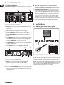
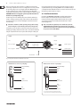
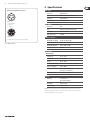
User Manual
ULTRA-DI PRO DI4000
Professional 4-Channel Active DI-Box
A50-00000-34078
2
ULTRA-DI PRO DI4000 User Manual
Table of Contents
Important Safety Instructions....................................... 3
Legal Disclaimer.............................................................. 3
Limited Warranty............................................................ 3
1. Introduction................................................................ 5
1.1 Before you begin.................................................................. 5
1.2 Online registration.............................................................. 5
1.3 Control elements................................................................. 6
2. Applications................................................................ 6
2.1 Tapping signal from a (bass) guitar............................... 6
2.2 Converting the output of a keyboard /
DJ-mixer / headphone plug.................................................... 7
2.3 Converting a microphone signal................................... 7
2.4 Tapping a signal from a power amplifier output..... 7
3. Installation.................................................................. 7
3.1 Rack mounting...................................................................... 7
3.2 Mains connection ............................................................... 7
3.3 Audio connections.............................................................. 8
4. Specifications.............................................................. 9
3
ULTRA-DI PRO DI4000 User Manual
Important Safety
Instructions
Terminals marked with this symbol carry
electrical current of sufficient magnitude
to constitute risk of electric shock. Use only
high-quality commercially-available speaker cables with
1/4" TS plugs pre-installed. All other installation or
modification should be performed only by
qualified personnel.
This symbol, wherever it appears,
alerts you to the presence of uninsulated
dangerous voltage inside the
enclosure - voltage that may be sufficient to constitute a
risk of shock.
This symbol, wherever it appears,
alerts you to important operating and
maintenance instructions in the
accompanying literature. Please read the manual.
Caution
To reduce the risk of electric shock, do
not remove the top cover (or the rear
section). No user serviceable parts inside. Refer servicing
to qualified personnel.
Caution
To reduce the risk of fire or electric shock,
do not expose this appliance to rain and
moisture. The apparatus shall not be exposed to dripping
or splashing liquids and no objects filled with liquids, such
as vases, shall be placed on the apparatus.
9. Do not defeat the safety purpose of the polarized
or grounding-type plug. A polarized plug has two blades
with one wider than the other. A grounding-type plug
has two blades and a third grounding prong. The wide
blade or the third prong are provided for your safety. If the
provided plug does not fit into your outlet, consult an
electrician for replacement of the obsolete outlet.
10. Protect the power cord from being walked on or
pinched particularly at plugs, convenience receptacles,
and the point where they exit from the apparatus.
11. Use only attachments/accessories specified by
the manufacturer.
12. Use only with the
cart, stand, tripod, bracket,
or table specified by the
manufacturer, or sold with
the apparatus. When a cart
is used, use caution when
moving the cart/apparatus
combination to avoid
injury from tip-over.
13. Unplug this apparatus during lightning storms or
when unused for long periods of time.
14. Refer all servicing to qualified service personnel.
Servicing is required when the apparatus has been
damaged in any way, such as power supply cord or plug
is damaged, liquid has been spilled or objects have fallen
into the apparatus, the apparatus has been exposed
to rain or moisture, does not operate normally, or has
been dropped.
15. The apparatus shall be connected to a MAINS socket
outlet with a protective earthing connection.
16. Where the MAINS plug or an appliance coupler is
used as the disconnect device, the disconnect device shall
remain readily operable.
Caution
These service instructions are for use
by qualified service personnel only.
To reduce the risk of electric shock do not perform any
servicing other than that contained in the operation
instructions. Repairs have to be performed by qualified
service personnel.
1. Read these instructions.
2. Keep these instructions.
3. Heed all warnings.
4. Follow all instructions.
5. Do not use this apparatus near water.
6. Clean only with dry cloth.
7. Do not block any ventilation openings. Install in
accordance with the manufacturer’s instructions.
8. Do not install near any heat sources such as
radiators, heat registers, stoves, or other apparatus
(including amplifiers) that produce heat.
LEGAL DISCLAIMER
TECHNICAL SPECIFICATIONS AND APPEARANCE
ARE SUBJECT TO CHANGE WITHOUT NOTICE.
THE INFORMATION CONTAINED HEREIN IS CORRECT
AT THE TIME OF PRINTING. ALL TRADEMARKS ARE
THE PROPERTY OF THEIR RESPECTIVE OWNERS.
MUSIC GROUP ACCEPTS NO LIABILITY FOR ANY
LOSS WHICH MAY BE SUFFERED BY ANY PERSON
WHO RELIES EITHER WHOLLY OR IN PART UPON
ANY DESCRIPTION, PHOTOGRAPH OR STATEMENT
CONTAINED HEREIN. COLORS AND SPECIFICATIONS
MAY VARY FROM ACTUAL PRODUCT. MUSIC GROUP
PRODUCTS ARE SOLD THROUGH AUTHORIZED
FULLFILLERS AND RESELLERS ONLY. FULLFILLERS AND
RESELLERS ARE NOT AGENTS OF MUSIC GROUP
AND HAVE ABSOLUTELY NO AUTHORITY TO BIND
MUSIC GROUP BY ANY EXPRESS OR IMPLIED
UNDERTAKING OR REPRESENTATION. THIS MANUAL
IS COPYRIGHTED. NO PART OF THIS MANUAL MAY
BE REPRODUCED OR TRANSMITTED IN ANY FORM
OR BY ANY MEANS, ELECTRONIC OR MECHANICAL,
INCLUDING PHOTOCOPYING AND RECORDING OF ANY
KIND, FOR ANY PURPOSE, WITHOUT THE EXPRESS
WRITTEN PERMISSION OF MUSIC GROUP IP LTD.
ALL RIGHTS RESERVED.
© 2011 MUSIC Group IP Ltd.
Trident Chambers, Wickhams Cay, P.O. Box 146,
Road Town, Tortola, British Virgin Islands
LIMITED WARRANTY
§ 1 Warranty
(1) This limited warranty is valid only if you purchased
the product from a MUSIC Group Authorized Reseller in
the country of purchase. A list of authorized resellers can
be found on BEHRINGER’s website behringer.com under
“Where to Buy“, or you can contact the MUSIC Group office
closest to you.
(2) MUSIC Group* warrants the mechanical and
electronic components of this product to be free of defects
in material and workmanship if used under normal
operating conditions for a period of one (1) year from
the original date of purchase (see the Limited Warranty
terms in § 4 below), unless a longer minimum warranty
period is mandated by applicable local laws. If the product
shows any defects within the specified warranty period
and that defect is not excluded under § 4, MUSIC Group
shall, at its discretion, either replace or repair the product
using suitable new or reconditioned product or parts.
In case MUSIC Group decides to replace the entire product,
this limited warranty shall apply to the replacement
product for the remaining initial warranty period, i.e.,
one (1) year (or otherwise applicable minimum warranty
period) from the date of purchase of the original product.
(3) Upon validation of the warranty claim, the repaired
or replacement product will be returned to the user freight
prepaid by MUSIC Group.
(4) Warranty claims other than those indicated above
are expressly excluded.
PLEASE RETAIN YOUR SALES RECEIPT. IT IS YOUR PROOF
OF PURCHASE COVERING YOUR LIMITED WARRANTY.
THIS LIMITED WARRANTY IS VOID WITHOUT SUCH PROOF
OF PURCHASE.
§ 2 Online registration
Please do remember to register your new BEHRINGER
equipment right after your purchase at behringer.com
under “Support” and kindly read the terms and conditions
of our limited warranty carefully. Registering your
purchase and equipment with us helps us process
your repair claims quicker and more efficiently.
Thank you for your cooperation!
§ 3 Return materials authorization
(1) To obtain warranty service, please contact the
retailer from whom the equipment was purchased.
Should your MUSIC Group Authorized Reseller not be
located in your vicinity, you may contact the MUSIC Group
Authorized Fulfiller for your country listed under
4
ULTRA-DI PRO DI4000 User Manual
“Support” at behringer.com. If your country is not
listed, please check if your problem can be dealt with
by our “Online Support” which may also be found under
“Support” at behringer.com. Alternatively, please submit
an online warranty claim at behringer.com BEFORE
returning the product. All inquiries must be accompanied
by a description of the problem and the serial number
of the product. After verifying the product’s warranty
eligibility with the original sales receipt, MUSIC Group
will then issue a Return Materials Authorization
(“RMA”) number.
(2) Subsequently, the product must be returned in
its original shipping carton, together with the return
authorization number to the address indicated by
MUSIC Group.
(3) Shipments without freight prepaid will not
be accepted.
§ 4 Warranty Exclusions
(1) This limited warranty does not cover consumable
parts including, but not limited to, fuses and batteries.
Where applicable, MUSIC Group warrants the valves or
meters contained in the product to be free from defects in
material and workmanship for a period of ninety (90) days
from date of purchase.
(2) This limited warranty does not cover the product
if it has been electronically or mechanically modified
in any way. If the product needs to be modified or
adapted in order to comply with applicable technical
or safety standards on a national or local level, in any
country which is not the country for which the product
was originally developed and manufactured, this
modification/adaptation shall not be considered a defect
in materials or workmanship. This limited warranty does
not cover any such modification/adaptation, regardless
of whether it was carried out properly or not. Under the
terms of this limited warranty, MUSIC Group shall not
be held responsible for any cost resulting from such a
modification/adaptation.
(3) This limited warranty covers only the product
hardware. It does not cover technical assistance for
hardware or software usage and it does not cover
any software products whether or not contained in
the product. Any such software is provided “AS IS”
unless expressly provided for in any enclosed software
limited warranty.
(4) This limited warranty is invalid if the factoryapplied serial number has been altered or removed from
the product.
(5) Free inspections and maintenance/repair work
are expressly excluded from this limited warranty, in
particular, if caused by improper handling of the product
by the user. This also applies to defects caused by normal
wear and tear, in particular, of faders, crossfaders,
potentiometers, keys/buttons, guitar strings, illuminants
and similar parts.
(6) Damage/defects caused by the following conditions
are not covered by this limited warranty:
• improper handling, neglect or failure to operate the
unit in compliance with the instructions given in
BEHRINGER user or service manuals;
• connection or operation of the unit in any way
that does not comply with the technical or safety
regulations applicable in the country where the
product is used;
• damage/defects caused by acts of God/Nature
(accident, fire, flood, etc) or any other condition that
is beyond the control of MUSIC Group.
(7) Any repair or opening of the unit carried out by
unauthorized personnel (user included) will void the
limited warranty.
(8) If an inspection of the product by MUSIC Group
shows that the defect in question is not covered by the
limited warranty, the inspection costs are payable by
the customer.
(9) Products which do not meet the terms of this
limited warranty will be repaired exclusively at the buyer’s
expense. MUSIC Group or its authorized service center will
inform the buyer of any such circumstance. If the buyer
fails to submit a written repair order within 6 weeks after
notification, MUSIC Group will return the unit C.O.D. with
a separate invoice for freight and packing. Such costs will
also be invoiced separately when the buyer has sent in a
written repair order.
(10) MUSIC Group Authorized Resellers do not sell new
products directly in online auctions. Purchases made
through an online auction are on a “buyer beware” basis.
Online auction confirmations or sales receipts are not
accepted for warranty verification and MUSIC Group will
not repair or replace any product purchased through an
online auction.
§ 5 Warranty transferability
This limited warranty is extended exclusively to the
original buyer (customer of authorized reseller) and is
not transferable to anyone who may subsequently
purchase this product. No other person (reseller, etc.)
shall be entitled to give any warranty promise on behalf
of MUSIC Group.
§ 6 Claim for damage
Subject only to the operation of mandatory applicable
local laws, MUSIC Group shall have no liability to the buyer
under this warranty for any consequential or indirect
loss or damage of any kind. In no event shall the liability
of MUSIC Group under this limited warranty exceed the
invoiced value of the product.
§ 7 Limitation of liability
This limited warranty is the complete and exclusive
warranty between you and MUSIC Group. It supersedes
all other written or oral communications related to this
product. MUSIC Group provides no other warranties for
this product.
§ 8 Other warranty rights and
national law
(1) This limited warranty does not exclude or limit the
buyer’s statutory rights as a consumer in any way.
(2) The limited warranty regulations mentioned herein
are applicable unless they constitute an infringement of
applicable mandatory local laws.
(3) This warranty does not detract from the seller’s
obligations in regard to any lack of conformity of the
product and any hidden defect.
§ 9 Amendment
Warranty service conditions are subject to change without
notice. For the latest warranty terms and conditions
and additional information regarding MUSIC Group’s
limited warranty, please see complete details online at
behringer.com.
* MUSIC Group Macao Commercial Offshore Limited of
Rue de Pequim No. 202-A, Macau Finance Centre 9/J, Macau,
including all MUSIC Group companies
5
ULTRA-DI PRO DI4000 User Manual
1. Introduction
Whether you are on the stage or in the studio, you often find that you need
to connect an audio source to your mixing console, but you don’t have the
appropriate connectors. For example, only few keyboards feature balanced
outputs; guitars should not be connected directly to the console; and placing
a microphone in front of an amp is not always an ideal solution, because the
mic will pick up unwanted signals from other instruments, too. Low frequency
signals (e.g. produced by a bass guitar) are particularly difficult to handle using
these techniques.
“DI” is short for “Direct Injection”. A Direct Inject box allows you to use a
high-impedance, unbalanced source, e.g. the signal between guitar and guitar
amp, and feed it directly into an input channel on your console, without having
to use a microphone. And that’s far from being all. There are plenty of situations
in which you’d like to input unbalanced source signals into your console,
and possibly convert them to balanced signals before. As you can expect,
the DI4000 offers you a reliable solution.
The following explanations will give you an introduction to the complex
performance-impedance issue: impedance is defined as the dependence of a
device’s electrical resistance and phase response on the frequency processed.
Thus, impedance is one of the criteria that distinguish good DI boxes from
poor ones. Much like in a power amp and its connected speakers, impedance
determines the performance of the device. With a good power amp, the load
impedance will have little influence on the maximum output power, but it can
considerably affect other properties. With a passive DI box, the connected load
impedances (ins and outs) alter the bandwidth, frequency response, distortion,
etc. of the DI box.
By the way: there are two basic types of DI boxes, passive and active. Both can
be connected to one of the console’s mic inputs. Passive DI boxes offer the
advantage that they are less expensive than active models (less electronics,
no power supply), however, their performance depends on the connected
impedance. With a passive DI box connected, any impedance change on the
console side will also modify the input impedance. The frequency response
will always depend on the impedances connected. Any passive DI box will only
perform properly with accurately specified impedances (high on the input side,
low at the output), i.e. it will only work in standard situations.
Active DI boxes such as our ULTRA-DI PRO, however, do not suffer from such
restrictions, because they use an amplifier circuit to buffer the input signal.
Since the ULTRA-DI PRO’s input impedance is ultra-high, the signal remains
unaffected as it passes through the DI box. Additionally, the ULTRA-DI PRO
features balanced impedances on the output side, making the signal less
susceptible to hum and noise interference. In this way, the signal as source
impedance is completely independent of the console used (and vice versa),
which means that the sound remains totally unaffected. The ULTRA-DI PRO uses
our proven OT-1 transformer which ensures a clear and distortion-free sound and
linear frequency response. Additionally, the ULTRA-DI PRO comes with a built-in
power supply.
Future-oriented BEHRINGER technology
The ULTRA-DI PRO is based on SMD technology (Surface Mounted Devices).
These subminiature components known from aerospace applications ensure both
extreme packing density and greater reliability.
High-quality components and design
The philosophy behind BEHRINGER products guarantees a no-compromise circuit
design and employs the best choice of components. The op-amps, type 4580,
used in the ULTRA-DI PRO are chosen for their superior signal-to-noise ratio,
low distortion and linear performance. Additionally, the ULTRA-DI PRO uses high
quality resistors and capacitors with very tight tolerances, high-grade switches
as well as other selected components.
◊ This manual first describes the terminology used, so that you can fully
understand the ULTRA‑DI PRO and its functions. Please read the manual
carefully and keep it for future reference.
1.1 Before you begin
Your BEHRINGER ULTRA-DI PRO was carefully packed in the factory and
the packaging was designed to protect the unit from rough handling.
Nevertheless, we recommend that you carefully examine the packaging and its
contents for any signs of physical damage, which may have occurred in transit.
◊ If the unit is damaged, please do not return it to us, but notify your
dealer and the shipping company immediately, otherwise claims for
damage or replacement may not be granted. Shipping claims must be
made by the consignee.
The BEHRINGER ULTRA-DI PRO fits into one standard 19" rack unit of space.
Please allow at least an additional 4" (10 cm) depth for the connectors on the
back panel.
◊ Be sure that there is enough space around the unit for cooling and
please do not place the ULTRA-DI PRO on high temperature devices such
as power amplifiers etc. to avoid overheating.
The mains connection of the ULTRA-DI PRO is made by using the supplied cable.
It meets all of the international safety certification requirements. Please make
sure that all units have a proper ground connection.
◊ Before you connect your ULTRA-DI PRO to the mains, please make sure
that your local voltage matches the voltage required by the unit!
1.2 Online registration
Please register your new BEHRINGER equipment right after your purchase
by visiting http://behringer.com and read the terms and conditions of our
warranty carefully.
Should your BEHRINGER product malfunction, it is our intention to have it
repaired as quickly as possible. To arrange for warranty service, please contact
the BEHRINGER retailer from whom the equipment was purchased. Should your
BEHRINGER dealer not be located in your vicinity, you may directly contact
one of our subsidiaries. Corresponding contact information is included in the
original equipment packaging (Global Contact Information/European Contact
Information). Should your country not be listed, please contact the distributor
nearest you. A list of distributors can be found in the support area of our website
(http://behringer.com).
Registering your purchase and equipment with us helps us process your repair
claims more quickly and efficiently.
Thank you for your cooperation!
6
ULTRA-DI PRO DI4000 User Manual
1.3 Control elements
◊ Only use the -20 dB switches if you are sure the Ultra-DI PRO is
The BEHRINGER ULTRA-DI PRO has four identical channels. The control elements
are identical on all channels.
(6)
(7)
clipping (overloading) and not your mic pre-amp. Always use as little
attenuation as possible to get the best possible signal-to-noise ratio.
(11) FUSE HOLDER/VOLTAGE SELECTOR. Please make sure that the voltage
indicated on the unit matches your local voltage, before you attempt to
connect and operate the VINTAGER AC112. Blown fuses may only be replaced
by fuses of the same type and rating. Some models allow for inserting the
fuse holder in two different positions, in order to switch over from 230 V
to 115 V operation, and vice versa. Please note that for 115 V operation
outside Europe, you need to use a fuse of a higher rating (see chapter 3
“Installation”). Use the enclosed power cord to connect the unit to the mains.
(12) To provide maximum flexibility the ULTRA-DI PRO is also fitted with an
unbalanced XLR INPUT to connect the source.
(1)
(2) (3)
(4) (5)
2. Applications
Fig. 1.1: Control and display elements on the front panel
(1) OUTPUT. This is the balanced output of the ULTRA-DI PRO. The connection
to the mixing desk should be made with a standard high-quality
balanced cable.
2.1 Tapping signal from a (bass) guitar
(2) +20 dB gain switch for pre-amplification of low level signals.
(3) Switchable HIGH CUT filters (8 kHz) for guitar applications (6 dB/Oct).
(4) With the PHASE REVERSE switch the input signal is reversed in phase
by 180°.
Microphone Input
(5) Use the GND LIFT switch to either connect the ground of input and output
or keep them completely separate. Depending on the grounding of the
connected devices linking or disconnecting will reduce hum or prevent
ground loops. GROUND LIFT on means no interconnection.
(6) The OUTPUT LEVEL meter displays the output level of the Ultra-DI PRO in a
range from ‑24 dB to +18 dB.
Out
DI4000
In
Link Out
(7) Use the POWER switch to turn on the BEHRINGER ULTRA-DI PRO.
(12)
(11)
(13)
Fig. 2.1: Guitar
(8)
(9) (10)
Fig. 1.2: Rear panel elements of the BEHRINGER Ultra-DI PRO
(8) LINK. This is the unbalanced parallel output of the ULTRA-DI PRO.
Connect this to the input of the backline or monitor amplifier.
(9) INPUT. Connect the source to this 1/4" jack to input the signal.
(10) and (13) The -20 dB ATTENUATION switches greatly increase the operating
range of the ULTRA-DI PRO. From the low level signals of a high impedance
guitar to the hot speaker terminals of a PA amplifier. Depressing both will
give 40 dB attenuation.
DI box
Guitar Amp/Mixer
This figure shows the standard application of any Direct Inject box. The signal to
the amplifier is unaffected, it is just tapped off to be routed to the microphone
input of the mixer. Especially bass guitars benefit from this application. It is
difficult to find a microphone which handles high level low frequencies well and
with a linear frequency response. Using the ULTRA-DI PRO will give you clean and
crisp sound. Connect the ULTRA-DI PRO after any effects devices, so that their
effect will be heard over the PA system or on the recording.
7
ULTRA-DI PRO DI4000 User Manual
2.2 Converting the output of a keyboard /
DJ-mixer / headphone plug
+red or positive post
In
In
Out
-black or negative post
Out
Out
In
-20 / -40 dB!
Microphone Inputs Pan left and right
Fig. 2.2: DJ-mixer
2 x DI box
mixer
This configuration can be used with a keyboard, DJ-mixer, headphone output,
drum kit or any (stereo or mono) line source. In all cases where you want to run
long lines, for instance to the FOH (Front Of House) desk. The signal can be linked
through to another amplifier, if the keyboard player/ DJ/etc. wants to have a
monitor connected independent of the foldback mix. The ULTRA-DI PRO acts as
both a ground isolator and an unbalanced to balanced converter.
2.3 Converting a microphone signal
In
Out
Fig. 2.4: Connection to an amplifier output
◊ Always make sure the GROUND LIFT is on (no ground link)
when connecting to speaker terminals. This prevents accidental
short-circuiting of the amplifier output. Also make sure the tip of the
input jack is connected to the red terminal and that the metal housing
of the DI4000 has no contact with other equipment.
3. Installation
Your BEHRINGER ULTRA-DI PRO was carefully packed in the factory and
the packaging was designed to protect the unit from rough handling.
Nevertheless, we recommend that you carefully examine the packaging and its
contents for any signs of physical damage, which may have occurred in transit.
◊ If the unit is damaged, please do not return it to us, but notify your
dealer and the shipping company immediately, otherwise claims for
damage or replacement may not be granted. Shipping claims must be
made by the consignee.
3.1 Rack mounting
Fig. 2.3: Connecting a microphone
Sometimes all that’s available (especially when all other mics are in use) is an
unbalanced high impedance microphone with an unbalanced jack. With the
ULTRA-DI PRO long cable runs to the console can be established without fear
of picking up noise and hum. Just plug the jack into the input and connect the
output to the console’s mic input.
2.4 Tapping a signal from a power
amplifier output
When no line out is available it is possible to connect an amplifier output directly
to the DI4000 (for example, recording direct from a guitar amplifier, TV-speaker,
etc). It is possible to connect the output, i.e. an extra speaker output, of up to
3000 Watts to the ULTRA-DI PRO without fear of overloading. Pay attention to the
two -20 dB buttons on the ULTRA-DI PRO! Both must be depressed if an amplifier
output is connected to the DI4000 input.
The BEHRINGER ULTRA-DI PRO fits into one standard 19" rack unit of space.
Please allow at least an additional 4" depth for the connectors on the back panel.
◊ Be sure that there is enough air space around the unit for cooling and
please do not place the ULTRA-DI PRO on high temperature devices such
as power amplifiers etc. to avoid overheating.
3.2 Mains connection
The mains connection of the ULTRA-DI PRO is made by using a mains cable
and a standard IEC receptacle. It meets all of the international safety
certification requirements.
◊ Please make sure that all units have a proper ground connection.
For your own safety, it is advisable not to remove the ground
connection within the units or at the supply, or fail to make this
connection at all.
8
ULTRA-DI PRO DI4000 User Manual
Before you switch on the unit, check that it is configured to match your AC
mains voltage requirements. If it does not comply, then it is necessary to switch
the operating voltage to the correct supply requirements BEFORE turning on
the unit, otherwise the unit could be severely damaged. You will find this
combined fuse holder/voltage selector at the back, adjacent to the IEC receptacle.
IMPORTANT: This does not apply for general export models which are
built for one operating voltage only.
needs replacing after the unit is repaired, please make sure that you replace it
only with the identical type and rating. NEVER use fuses of different ratings or
cover faulty fuses with aluminium foil. This can cause fire and electric shocks and
will endanger your life and the lives of others.
3.3 Audio connections
The AC voltage selection is defined by the position of the fuse holder. If you
intend to change the operating voltage, remove the fuse holder and twist it
by 180 degrees before you reinsert it. Matching the two markers shows the
selected voltage.
As standard, the BEHRINGER ULTRA-DI PRO is installed with transformerbalanced outputs. This transformer features automatic hum and noise
reduction for balanced signals and thus allows for trouble-free operation,
even at high operating levels. Externally induced mains hum etc. will be
effectively suppressed.
◊ If the unit is switched to another operating voltage, the fuse rating
◊ Please ensure that only qualified persons install and operate the
must be changed. See the technical specifications in the appendix.
A safety fuse protects the unit from serious defects. If the fuse blows, this is a
warning sign and always indicates that the circuit is overloaded. The fault must
always be repaired before the fuse is replaced. If the safety fuse is faulty and
Output
ULTRA-DI PRO. During installation and operation the user must have
sufficient electrical contact to earth. Electrostatic charges might affect
the operation of the ULTRA-DI PRO!
Cable
Input
Pin 1
Pin 2 = (+) Signal
Ground
2 1
3
Shield
(+) Signal + Hum
(-) Signal + Hum
Pin 3 = (-) Signal
1
2
3
Positive
(+) Hum + Signal
Negative
(-) Hum + Signal
2 x Signal
= Signal + 6 dB
RFI and Hum
Fig. 3.1: Compensation of interference with balanced connections
Unbalanced use of mono ¼" jack plugs
Balanced use of stereo ¼" jack plugs
strain relief clamp
strain relief clamp
sleeve
sleeve
ring
tip
tip
sleeve
(ground/shield)
sleeve
ground/shield
ring
cold (-ve)
tip
(signal)
tip
hot (+ve)
For connection of balanced and unbalanced plugs,
ring and sleeve have to be bridged at the stereo plug.
9
ULTRA-DI PRO DI4000 User Manual
4. Specifications
Balanced use with XLR connectors
2 1
3
input
1 = ground/shield
2 = hot (+ve)
3 = cold (-ve)
1
2
3
output
For unbalanced use, pin 1 and pin 3 have to be bridged
Fig. 3.2: Different plug types
Audio Input
Connectors
XLR and 1/4" jack
Type
DC-decoupled, unbalanced input
Impedance max. 220 kOhm
Max. input level
+20/+40/+60 dBu
Audio Output
ConnectorsXLR
Type transformer-balanced output stage
Impedance
600 Ohms balanced
Max. output level
+20 dBu
System Specifications
Bandwidth (100 kOhm)
23 Hz to 120 kHz (±3 dB)
Bandwidth (600 Ohm)
23 Hz to 27 kHz (±3 dB)
Bandwidth (High Cut)
10 Hz to 8 kHz (±3 dB)
Noise -95 dBu
Power Supply
Mains Voltages
USA/Canada
120 V~, 60 Hz
U.K./Australia
240 V~, 50 Hz
Europe
230 V~, 50 Hz
General export model
100 - 120 V~, 200 - 240 V~, 50 - 60 Hz
Power consumption
max. 10 Watts
Fuse
100 - 120 V~: T 200 mA H
200 - 240 V~: T 100 mA H
Mains connection
standard IEC receptacle
Physical
Dimension
1 ¾ x 19 x 8 ½"
44.5 x 482.6 x 215 mm
Net weight
5.9 lbs / 2.7 kg
Shipping weight
7.7 lbs / 3.5 kg
BEHRINGER is constantly striving to maintain the highest professional standards. As a result of these efforts,
modifications may be made from time to time to existing products without prior notice. Specifications and
appearance may differ from those listed or illustrated.
We Hear You