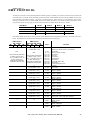
1
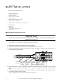
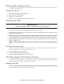
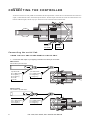
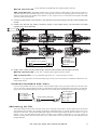
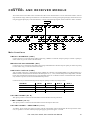
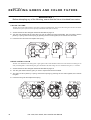
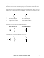
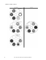
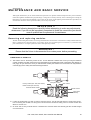
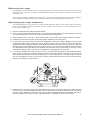
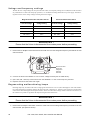
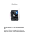
PAL 1200 (E, FX)
user manual
INTRODUCTION ................................................................................................................ 3
Common features ..................................................................................................................................................... 3
About this manual .................................................................................................................................................... 4
SAFETY .............................................................................................................................. 5
To protect yourself and others from electric shock .................................................................................................. 5
To protect yourself and others from UV radiation and lamp explosion .................................................................... 5
To protect yourself and others from burns and fire .................................................................................................. 5
To protect yourself and others from injury due to falls ............................................................................................. 5
BASIC INSTALLATION ...................................................................................................... 6
Mounting the pan/tilt unit .......................................................................................................................................... 6
Removing the transport fixture ................................................................................................................................. 7
Fitting the mirror ....................................................................................................................................................... 7
Installing the lamp .................................................................................................................................................... 7
Fitting the mains plug ............................................................................................................................................... 7
Checking voltage and frequency settings ................................................................................................................ 7
Rigging the PAL ....................................................................................................................................................... 7
CONNECTING THE CONTROLLER .................................................................................. 8
Connecting the serial link ......................................................................................................................................... 8
Addressing the PAL ................................................................................................................................................. 9
Switching on ........................................................................................................................................................... 10
Operating the fixture ............................................................................................................................................... 10
REMOTELY CONTROLLABLE FUNCTIONS .................................................................. 11
CONTROL AND RECEIVER MODULE ............................................................................ 13
Main functions ........................................................................................................................................................ 13
Special functions (SPEC) ....................................................................................................................................... 14
Error and information messages ............................................................................................................................ 15
REPLACING GOBOS AND COLOR FILTERS ................................................................. 16
MAINTENANCE AND BASIC SERVICE .......................................................................... 19
Removing and replacing modules .......................................................................................................................... 19
Cleaning the optical path ........................................................................................................................................ 20
Replacing the lamp ................................................................................................................................................ 21
Optimizing the lamp alignment ............................................................................................................................... 21
Voltage and frequency settings .............................................................................................................................. 22
Regenerating malfunctioning lamps ....................................................................................................................... 22
Reconfiguring the optical path ................................................................................................................................ 23
Accessing the electronics section .......................................................................................................................... 23
Replacing fuses ...................................................................................................................................................... 24
Updating the software ............................................................................................................................................ 24
Adjusting the mirror dampers ................................................................................................................................. 26
DMX PROTOCOL ............................................................................................................. 27
TECHNICAL SPECIFICATIONS ...................................................................................... 30
SPEC SEQUENCES ........................................................................................................ 32
ERROR AND INFORMATION MESSAGES .................................................................... 34
TROUBLESHOOTING GUIDE ......................................................................................... 35
© 1996 - 2000 Martin Professional A/S, Denmark.
All rights reserved. No part of this manual may be
reproduced, in any form or by any means, without
permission in writing from Martin Professional A/S,
Denmark.
Printed in Denmark.
P/N 35000022, Revision B
section 1
INTRODUCTION
Congratulations on your choice of the PAL 1200, PAL 1200 E, or PAL 1200 FX, designed and manufactured by Martin Professional. The PAL is a high performance automated profile luminaire that provides endless possibilities for lighting designers in
a variety of applications. Rugged construction and high quality components ensure that your PAL will perform reliably for
many years.
Common features
•
•
•
•
•
•
•
•
•
•
•
•
•
•
•
•
•
•
•
•
•
•
•
•
•
•
•
•
•
Choice of Osram or Philips 1200 W discharge lamp.
Remote lamp ON / OFF via controller.
Highly efficient optical system with precision coated lenses ensures very high light output.
Flat field using hot-spot elimination filter.
Smooth and accurate movement.
287º pan by 85º tilt (10,200 by 1,504 positions).
8 and 16-bit pan/tilt tracking and vector protocols via DMX 512.
0 to 100% smooth dimming with micro-stepping resolution.
CMY subtractive color mixing system for wide range of mixable colors.
Instant color snaps and seamless fades.
Excellent color uniformity.
4 rotating and indexible gobos, one fixed and one open.
Standard D-size easily interchangeable.
Motorized focus.
15º to 26º motorized zoom.
Optional narrow angle (10.5º to 14º) or wide angle (20º to 36º).
Variable motorized wash filter.
Modular design for ease of servicing and flexibility.
Easy access to serviceable parts.
Adjustable mounting bracket with graduated scale (+70º/-60º).
Control by DMX-512 and Martin RS-485 protocols.
Simple digital address setting via control module with 4-digit LED display.
Simple setting for pan and tilt invert, and pan/tilt swap.
Digital read-out of lamp and fixture usage.
Power Factor Correction for low current consumption.
Silent fan cooling.
Remote control of fan speed.
Overheating protection.
Access door cut-off switch.
T h e PA L 1 2 0 0 a n d PA L 1 2 0 0 E f e a t u r e
•
•
•
Four individually controlled profile shutters in a frame that swivels 45º.
Five interchangeable dichroic color filters including color temperature corrector (CTC).
Option for installing metal and glass gobos on color wheel.
T h e PA L 1 2 0 0 F X f e a t u r e s
•
•
•
•
5% to 100% motorized iris.
2 additional rotating and indexible gobos.
2 additional fixed gobos.
Rotating 3-facet prism.
T h e PA L 1 2 0 0 E f e a t u r e s
•
•
Flicker-free operation suitable for digital and high-speed television cameras.
Power-saving standby mode.
PAL 1200, PAL 1200 E, PAL 1200 FX User Manual
3
About this manual
This manual covers the following fixtures:
•
•
•
The PAL 1200 with automated framing shutters and magnetic ballast
The PAL 1200 E with automated framing shutters and electronic ballast
The PAL 1200 FX with iris and additional rotating effects and magnetic ballast
“PAL” is used in this manual when describing features or procedures common to all 3 models.
The software versions are shown below. Update information and the latest documentation is available from the Martin web site
at http://www.martin.dk.
PAL 1200, PAL 1200 E
Device
PCB
CPU
Receiver
CPU
EPROM
CPU
EPROM
4
A-section
B-section
Designator
Software version
PAL 1200 FX
P/N
Software version
P/N
IC101
1.3
62122013
1.1
62122014
IC101
2.0
62122024
2.0
62122024
IC102
2.0
62121021
1.2
62121023
IC101
2.0
62122024
2.0
62122024
IC102
1.7
62121019
1.1
62121022
PAL 1200, PAL 1200 E, PAL 1200 FX User Manual
section 2
SAFETY
WARNING!
This product is for professional use only. It is not for household use.
This product presents risks of lethal or severe injury due to fire and heat, electric shock, ultraviolet radiation, lamp explosion,
and falls. Read this manual before powering or installing the fixture, follow the safety precautions listed below and observe
all warnings in this manual and printed on the fixture. If you have questions about how to operate the fixture safely, please contact your Martin dealer or call the Martin 24-hour service hotline at +45 70 200 201.
To protect yourself and others from electric shock
•
•
•
•
•
Disconnect the fixture from AC power before removing or installing the lamp, fuses, or any part, and when not in use.
Always ground (earth) the fixture electrically.
Use only a source of AC power that complies with local building and electrical codes and has both overload and ground-fault
protection.
Do not expose the fixture to rain or moisture.
Refer any service operation not described in this manual to a qualified technician.
To protect yourself and others from UV radiation and lamp explosion
•
•
•
•
Never operate the fixture with missing or damaged lenses and/or covers.
When replacing the lamp, allow the fixture to cool for at least 15 minutes before opening the fixture or removing the lamp. Protect your hands and eyes with gloves and safety glasses.
Do not stare directly into the light. Never look at an exposed lamp while it is lit.
Replace the lamp if it becomes defective or worn out, or before usage exceeds the maximum service life.
To protect yourself and others from burns and fire
•
•
•
•
•
•
•
•
Never attempt to bypass the thermostatic switch or fuses. Always replace defective fuses with ones of the specified type and
rating.
Keep all combustible materials (for example fabric, wood, paper) at least 0.5 meters (20 inches) away from the fixture. Keep
flammable materials well away from the fixture.
Do not illuminate surfaces within 1 meter (39 inches) of the fixture.
Provide a minimum clearance of 0.1 meters (4 inches) around fans and air vents.
Never place filters or other materials over the lens or mirror.
The exterior of the fixture becomes very hot during operation. Allow the fixture to cool for at least 5 minutes before handling.
Do not modify the fixture or install other than genuine Martin parts.
Do not operate the fixture if the ambient temperature (Ta) exceeds 40° C 104° F).
To protect yourself and others from injury due to falls
•
•
•
•
When suspending the fixture above ground level, verify that the structure can hold at least 10 times the weight of all installed
devices.
Hang the fixture by the mounting bracket only: do not the carrying handles for primary or secondary attachment.
Verify that all external covers and rigging hardware are securely fastened and use an approved means of secondary attachment
such as a safety cable.
Block access below the work area whenever installing or removing the fixture.
PAL 1200, PAL 1200 E, PAL 1200 FX User Manual
5
section 3
B A S I C I N S TA L L AT I O N
Before operating the PAL you need to:
•
•
•
•
•
•
•
Mount the pan/tilt unit.
Remove the transport fixture.
Fit the pan/tilt mirror.
Install a lamp (not included).
Fit a mains plug.
Check voltage and frequency settings.
Rig the fixture in its location.
The PAL comes complete with the following items:
•
•
•
•
•
Hanging bracket
Pan/tilt unit
Pan/tilt mirror
5 meter XLR-XLR control cable
User manual
Mounting the pan/tilt unit
I M P O R TA N T
Never disconnect the pan and tilt cables while the PAL is under power. Doing so will
damage the driver ICs.
This procedure is not required for units shipped from the factory in flight cases.
1. Release the four thumbscrews located on the top front of the PAL.
2. Attach the safety wire of the pan/tilt unit to the dedicated hole in the PAL body.
3. Connect the pan and tilt cables from the pan/tilt unit to the terminals on the body. Ensure that the connectors are pressed firmly into place.
Pan/tilt unit.
Securing
points for
retaining
screws.
Hole for
attaching
safety
hook.
thumbscrews for
securing
pan/tilt unit.
Space for
pan/tilt
cable and
safety wire.
Connectors for
pan/tilt
wires.
4. Place the pan/tilt unit on top of the PAL so that the four securing points are right in front of the retaining
thumbscrews. Verify that the pan/tilt cable and the safety wire fit properly in the space under the pan/tilt
shaft.
5. Slide the pan/tilt unit towards the rear of the PAL so that the securing points and the thumbscrews slide into
one another. Tighten the thumb screws.
To remove the pan/tilt unit, follow the above procedure in the reverse order.
6
PAL 1200, PAL 1200 E, PAL 1200 FX User Manual
Removing the t ranspor t f ixture
In order to protect the pan/tilt assembly from becoming damaged during shipment it has been secured with black plastic straps.
Cut and remove these plastic straps.
Fitting the mirror
1. Release the two thumbscrews on the tilt motor.
2. Place the mirror on the tilt motor.
3. Tighten the two thumbscrews.
4. Carefully remove the surface protection foil from the mirror.
Installing the lamp
WA R N I N G !
Make sure that the fixture is isolated from the mains supply.
The PAL may be used with either the Osram HSR 1200 or the Philips MSR 1200 lamp.
1. Remove the three screws that secure the access plate of the lamp socket assembly at the rear of the PAL and withdraw the lamp socket assembly.
2. Hold the lamp by the ceramic parts, avoiding touching the glass part with your fingers, and carefully insert it
into the lamp socket. If you accidentally touch the glass part with your fingers you must clean it thoroughly
with the cleaning cloth supplied with the lamp. You can also use a clean lint free cloth wetted with alcohol.
3. Replace the lamp socket assembly, ensuring that the lamp locates properly into the aluminum reflector, and
tighten the Philips screws.
N O T E : The lamp position is adjusted at the factory, however, re-adjustment may be necessary to optimize the light output
and the color uniformity with the CMY (Cyan, Magenta, Yellow) system. Please refer to “Optimizing the lamp alignment” on
page 21.
Fitting the mains plug
The PAL is delivered from the factory without a plug on the mains cable. You will have to fit a plug that conforms to your local
mains outlet. The double-insulated mains cable contains three wires.
1. Connect the BROWN wire to the LIVE pin.
2. Connect the BLUE wire to the NEUTRAL pin.
3. Connect the YELLOW/GREEN wire to the EARTH pin.
C h e ck i n g vo lt ag e a n d f r e q u e n cy s e t ti n g s
It is vital that both voltage and frequency settings of the PAL match the local power supply. If this is not the case, you will have
to rewire the fixture as described under “Voltage and frequency settings” on page 22. The factory setting of voltage and frequency is printed on the serial number label at the back of the fixture.
R i g g i n g t h e PA L
You can now rig the fixture by means of its mounting bracket. The PAL has a graduated scale on each side of the body which
allows you to align it with other fixtures. The mounting bracket allows you to tilt the fixture from 70° up to 60° down. Use the
lever handles on the sides to lock the fixture into the desired angle.
PAL 1200, PAL 1200 E, PAL 1200 FX User Manual
7
section 4
CONNECTING THE CONTROLLER
All effects in the PAL are fully DMX-512 and Martin RS-485 implemented. Control data is transmitted from the controller’s
output, via XLR data link cables, to the data input on the PAL. The data output on the PAL allows the serial data link to be continued to additional lights, and this way up to 32 fixtures can be connected on the same data link.
Data output
via 3 pin
XLR female.
Data input
via 3 pin
XLR male.
Connecting the serial link
U S I N G T H E PA L A N D O T H E R M A R T I N L I G H T S O N LY
1. Connect the data output of your lighting controller to the data input on the PAL.
DMX Controller
with standard 5 pin XLR output.
5 pin XLR male:
Pin 1: GND (screen)
Pin 2: Signal (-)
Pin 3: Signal (+)
Pin 4: N/C
Pin 5: N/C
3 pin XLR female:
Pin 1: GND (screen)
Pin 2: Signal (+)
Pin 3: Signal (-)
Martin Controller
with standard 3 pin XLR output.
3 pin XLR male:
Pin 1: GND (screen)
Pin 2: Signal (+)
Pin 3: Signal (-)
8
3 pin XLR female:
Pin 1: GND (screen)
Pin 2: Signal (+)
Pin 3: Signal (-)
PAL 1200, PAL 1200 E, PAL 1200 FX User Manual
M A R T I N C O N T R O L L E R : Use the XLR-XLR or DSUB-XLR cable supplied with the controller.
D M X C O N T R O L L E R : Most DMX controllers have 5 pin XLR sockets for data output. For this reason you must use a
cable that adapts from the 5 pin DMX output to the 3 pin XLR input on the PAL. The following figure shows the proper connections in such a cable (P/N 11820003). Note that the (+) and (-) signal wires are reversed between the output of the DMX
controller and the input of the PAL.
2. Connect the data output of the first PAL to the data input of the next using the XLR-XLR cable supplied with
the PAL.
3. Continue the link this way, always connecting output to input (daisy-chain), until all fixtures are linked
together (max. 32 per data link).
Use standard 3 pin XLR/XLR data cables to
connect the lights. Pin 1 = screen,
pin 2 = signal (+), pin 3 = signal (-).
Remember to
insert XLR
termination plug in
the last light on the
data link.
4. Finally, insert a male XLR termination plug in the free output socket of the last light on the link.
M A R T I N C O N T R O L L E R : Use the 120 Ω termination plug supplied with the controller.
D M X C O N T R O L L E R : Use a 3 pin XLR male plug with a 120 Ω resistor between pins 2 and 3.
N O T E : It is very important to insert the termination plug to ensure correct and error-free communication between the controller and the fixtures.
INSERTING NON-MARTIN DMX LIGH TS
If you are using a DMX controller it is possible to insert non-Martin lights, using 5 pin XLRs in and out, on the link. In this
case you will need a cable that adapts from the 3 pin XLR female output on the preceding Martin light to the 5 pin XLR male
input on the next non-Martin DMX light. The connections in such a cable (P/N 11820002) are shown in the following figure.
3 pin XLR male:
Pin 1 = GND (screen)
Pin 2 = signal (+)
Pin 3 = signal (-)
Martin Output to DMX Input
5 pin XLR female:
Pin 1 = GND (screen)
Pin 2 = signal (-)
Pin 3 = signal (+)
Pin 4 = N/C
Pin 5 = N/C
A d d r e s s i n g t h e PA L
The control module on the left side of the PAL allows you to assign the fixture address, which is defined as the first channel
from which the PAL responds to the controller. Depending on which DMX mode you selected, the PAL requires more or less
channels for control. E.g., if the particular DMX mode requires 22 channels and you address the fixture to channel 1, it will use
channels 1 to 22. You must address the PAL fixtures according to your controller configuration, or vice versa, ensuring no
channels are being used by more than one fixture. If two or more fixtures of the same type share the same address they will
perform identically.
PAL 1200, PAL 1200 E, PAL 1200 FX User Manual
9
1. Switch on the PAL1200 (E) and wait until the reset has finished (see ‘Switching On’ below).
2. Press [menu] once to access the main menu and browse through the options, using the arrow keys, until the
display shows ‘dAdr’ or ‘Adr’ depending on whether you want to assign the fixture a DMX or Martin address,
respectively. Confirm by pressing [enter].
3. Use the arrow keys to select the desired address and confirm by pressing [enter].
The DMX channel requirements are listed in the following table. The PAL requires 2 channels when operated via a Martin RS485 controller.
DMX Mode
Pan / tilt resolution
control
Mode 1
Mode 2
Mode 3
Mode 4
8 bit
16 bit
8 bit
16 bit
Tracking
Tracking / Vector
PAL 1200, PAL 1200 E
22 channels
24 channels
26 channels
PAL 1200 FX
16 channels.
18 channels
20 channels
Switching on
After switching on, the PAL will index all effects and return these to their default positions. Some effects use a mechanical
indexing method causing some noise. This noise is completely normal and only lasts for a short period of time. The display on
the side of the fixture will show the software versions installed in the PAL and then advance to protocol auto-detect. As soon as
data is transmitted from your controller, the PAL automatically detects whether it is a Martin RS-485 or DMX 512 controller
and responds accordingly. When this occurs the display reads “PASS.”
Operating the fixture
If you are using a Martin RS-485 controller then please refer to that controller’s manual for further operating instructions. If
you are using a DMX 512 controller then please refer to the DMX 512 protocol listed in appendix A of this manual. The functions are briefly described under “REMOTELY CONTROLLABLE FUNCTIONS” on page 11.
N O T E : The PAL is fitted with a remotely operated lamp relay, allowing the lamp to be switched on and off via the controller
without affecting other functions of the fixture. However, after switching on the PAL, the lamp itself remains OFF until a
‘Lamp ON’ command is sent from the controller. Any attempt to start the lamp within 4 minutes after having switched it off,
will be ignored by the lamp circuit, however, the PAL stores the instruction and automatically ignites the lamp once the 4
minute period has expired. This is to ensure a safe strike of the lamp.
When switching on the lamp, the PAL draws a surge (peak) current which may be several times the normal operating current.
For this reason, it is suggested that you program a ‘Lamp On’ sequence at the controller, which will turn on the lamps one at a
time with an interval between each ‘Lamp On’ command of approximately 5 seconds.
10
PAL 1200, PAL 1200 E, PAL 1200 FX User Manual
section 5
R E M O T E LY C O N T R O L L A B L E F U N C T I O N S
This section briefly describes the various functions that can be remotely controlled via the serial data input on the fixture.
LAMP
The PAL uses the Philips MSR 1200 or the Osram HSR 1200 lamp and is fitted with a relay that allows the lamp to be
switched on and off via the controller. After switching on the PAL, the lamp itself remains OFF until a ‘Lamp ON’ command
is sent from the controller. Any attempt to start the lamp within 4 minutes after having switched it off will be ignored by the
lamp circuit. However, the PAL stores the instruction and automatically ignites the lamp once the 4 minute period has expired.
When switching on the lamp, the PAL draws a surge (peak) current which may be several times the normal operating current.
For this reason, it is suggested that you program a ‘Lamp On’ sequence at the controller, which turns on the lamps one at a time
with an interval between each ‘Lamp On’ command of approximately 5 seconds. This is to ensure a safe strike of the lamp.
N O T E : To avoid accidentally switching off the lamp, the ‘Lamp Off’ feature is only supported by DMX-512 if enabled on
the control module (see “LAMP OFF VIA DMX (LoFF)” on page 14) or if cyan, magenta and yellow channels are set to a certain value (see appendix A).
M OV E M E N T
The pan/tilt mirror on the PAL allows you to move the beam to any desired position within the range of 287º by 85º and micro
stepping control of the motors ensures smooth and accurate movement at all speeds. 10,200 positions on pan and 1,504 positions on tilt can be achieved when using either a Martin controller or 16-bit pan/tilt resolution via DMX. Selecting the B/O
speed will blackout the fixture whilst moving the mirror.
COLOR WHEEL
The color wheel offers five easily interchangeable dichroic color filters, plus an open white position. The B/O speed will
blackout the fixture whilst changing from one color to another.
CMY - COLOR MIXING
The CMY color mixing system is based on three sets of color flags: Cyan, Magenta and Yellow. These filters can be adjusted
individually between 0 and 100%. A wide range of colors can be produced by proportionally inserting one or two of the three
color flags at the same time. The precise color is determined by the percentage (0 to 100%) of each color flag which is applied.
Instant color changes are achieved when programming the color flags with a high speed. Slower speeds provide a smooth
cross-fade from one color into another. Please note that an optimized lamp adjustment is very important for perfect color uniformity across the beam.
R O TAT I N G G O B O S
Four rotating, indexible gobos, two fixed and one open, can be selected. All rotating gobos are bi-directional and can be programmed to any desired orientation. The B/O speed blacks out the fixture whilst changing the gobo or the orientation of the
gobo.
R O TAT I N G E F F E C T S ( PA L 1 2 0 0 F X )
Three rotating indexible gobos/effects, one fixed and one open, can be selected. All rotating effects are bi-directional and can
be programmed to any orientation. The B/O speed blacks out the fixture whilst changing gobos or orientation.
DIMMER/SHUTTER
High resolution, 0 to 100% smooth dimming is provided by the combined dimmer/shutter system. Use a high speed for dimming if you wish to open or close the dimmer/shutter instantly.
FOCUS
Motorized focus allows remote focusing at any time.
ZOOM
Motorized zoom allows you to vary the beam angle between 15 and 26º.
F R A M I N G S H U T T E R S ( PA L 1 2 0 0 , PA L 1 2 0 0 E )
Four shutters, each individually controlled by two motors, allow you to produce almost any desired frame. In addition, the
entire frame can be swivelled +/- 22.5º from the default position.
PAL 1200, PAL 1200 E, PAL 1200 FX User Manual
11
I R I S ( PA L 1 2 0 0 F X )
The beam diameter can be reduced from 100% to 5% using the motorized iris.
VA R I A B L E WA S H
Inserting the wash filter produces a wash-light effect. The effect of the wash filter can be varied over a wide range depending
on the proportion of the filter used.
FA N
The PAL is efficiently cooled by means of its low-noise axial fans. It is possible to reduce fan speed should extremely silent
performance be required. Low fan speed reduces the cooling of the fixture and should only be used when the ambient temperature is 25°C or lower. If the temperature inside the fixture exceeds a certain level (the cut-out threshold), a built-in thermostat
automatically switches off the lamp. This situation, which should be avoided, may occur if the fixture is operated with low
fan speed over a long period of time in high temperature surroundings.
N O T E : When switching off the lamp, the fans automatically power off after 4 minutes.
12
PAL 1200, PAL 1200 E, PAL 1200 FX User Manual
section 6
CONTROL AND RECEIVER MODULE
The control and receiver module on the side of the PAL offers several useful features. You can set the fixture address, read out
lamp and fixture usage, enable special features etc. The main-menu is accessed by pressing the [menu] key and can be browsed
using the [up] and [down] keys. The menu hierarchy is shown in the following diagram, which includes the ‘SPEC’ sub menu.
Fixture Address
PAn
Inv
tILt
nInv
Inv
PAtI
nInv
SUAP
dAdr
Adr
PSEt
1-512
1-31
0-4
dnLd
rES
n SU
SPEC
Po H
dISP
on
LA H
r Po
Auto
OFF
on
r LA
LoFF
OFF
on
dPr2
OFF
on
dFOF
dFSE
d Ad
c Ad
n Ad
y Ad
Sure
Sure
0-255
0-255
0-255
0-255
SP 1
OFF
St 1
...............
St99
St 1
SP16
St99
Main functions
DMX 512 ADDRESS (dAdr)
Use the arrow keys to select the fixture address when using a DMX-512 controller and press [enter] to confirm or [menu] to
cancel. Either way you will return to the main menu.
MART IN RS -485 ADDRESS (A dr)
Use the arrow keys to select the fixture address when using a Martin RS-485 controller and press [enter] to confirm or [menu]
to cancel. Either way you will return to the main menu.
P R O T O C O L S E T- U P ( P S E t )
After switching on the PAL, it automatically detects whether the controller is transmitting DMX 512 or Martin RS-485. If a
DMX controller is detected the PAL defaults to the DMX protocol (1, 2, 3 or 4) selected in the protocol setup (PSEt). The table
below shows the difference between the four available DMX protocols. If a Martin controller is detected the PAL automatically switches to protocol 0, which is the Martin RS-485 protocol.
Use the arrow keys to select the desired protocol and press [enter] to confirm or [menu] to cancel.
DMX Mode
Mode 1
Pan / tilt resolution
control
8 bit
Mode 2
Mode 3
Mode 4
16 bit
8 bit
16 bit
Tracking
Tracking / Vector
PAL 1200, PAL 1200 E
22 channels
24 channels
26 channels
PAL 1200 FX
16 channels.
18 channels
20 channels
F I X T U R E U S AG E ( P o H )
This option provides a read-out of the total number of hours the PAL has been powered on.
L A M P U S AG E ( L A H )
This option provides a read-out of the total number of hours the lamp has been used.
F I X T U R E U S AG E - R E S E TA B L E ( r P o )
As with the ‘Po H’ counter, this option provides a read-out of the number of hours that the PAL has been powered on. However, it is possible to reset this counter by keeping the [up] key pressed for approx. 5 seconds.
PAL 1200, PAL 1200 E, PAL 1200 FX User Manual
13
L A M P U S AG E - R E S E TA B L E ( r L A )
As with the ‘La H’ counter, this option provides a read-out of the number of hours the lamp has been powered on. However, it
is possible to reset this counter by keeping the [up] key pressed for approx. 5 seconds. Use this facility to reset the counter
whenever replacing the lamp to keep track of lamp life.
Special functions (SPEC)
Selecting this function presents you with a sub-menu of special functions. As in the main-menu, you can browse through the
options and select the one displayed by pressing [enter].
AU T O M AT I C B L A C K O U T O F D I S P L AY ( d I S P )
Use the arrow keys to toggle between ‘on’ and ‘off’. Select ‘on’ by pressing [enter], if you wish the display to blackout 2 minutes after the last press of any of the keys, in order to avoid audience distraction. Otherwise, select ‘off’. The blackout function
will not affect the appearance of error and information messages.
P R O T O C O L AU T O - D E T E C T ( A u t o )
This option can be used to disable the protocol auto-detect function when switching on the fixture. Use the arrow keys to toggle between on and off. Select ‘on’, by pressing [enter], if you wish the protocol auto-detect function to be enabled after
switching on the fixture, and ‘off’ if you wish to disable this function.
If protocol auto-detect is disabled (Auto = OFF) the PAL defaults to the protocol selected in the protocol set-up (0 = Martin, 1
= DMX1, 2 = DMX2, 3 = DMX3 or 4 = DMX4).
PA N I N V E R T ( PA n )
This function allows you to invert the pan movement (DMX protocol only). Use the arrow keys to toggle between ‘Inu’ for
inverted pan, and ‘nInu’ for non inverted and press [enter] to confirm or [menu] to cancel. Either way you will return to the
SPEC-menu.
T I LT I N V E R T ( t i L t )
This function allows you to invert the tilt movement (DMX Protocol only). Use the arrow keys to toggle between ‘Inu’ for
inverted tilt, and ‘nInu’ for non inverted and press [enter] to confirm or [menu] to cancel. Either way you will return to the
SPEC-menu.
N O T E : If using the Martin 3032 Controller, pan and tilt invert can be enabled from the link configuration menu.
PA N A N D T I LT S WA P ( PA t I )
This function allows you to swap the pan and tilt channels in DMX. Use the arrow keys to toggle between ‘SUAP’ for
swapped protocols and ‘n SU’ for non swapped and press [enter] to confirm or [menu] to cancel. Either way you will return to
the SPEC-menu.
D OW N L O A D ( d n L d )
For factory programming only - do not use.
RESET OF RECEIVER MODULE (rES)
Pressing [enter] on this option resets the receiver CPU and activates the protocol auto-detect function.
LAMP OFF VIA DMX (LoFF)
This option allows you to enable/disable the ‘Lamp Off’ function via DMX. Use the arrow keys to toggle between ‘on’ and
‘off’ and select ‘on’ by pressing [enter] if you wish to enable this feature and ‘off’ if you wish to disable the feature.
S P E C I A L D M X P ROTO C O L ( d P r 2 )
This option applies for the PAL 1200 and PAL 1200 E only - not the PAL 1200 FX - and should be enabled only when operated
by MA Lighting’s “Scancommander”. The ‘dPr2’ option reconfigures the DMX channel configuration, thus enabling the Scancommander to control the PAL 1200 as if it were two individual fixtures (consult appendix A for the DMX channel configuration). The protocol may be suitable for other lighting controllers with limitations in terms of the number of DMX channels
available per fixture.
Use the arrow keys to toggle between ‘on’ and ‘off’ and select ‘on’ by pressing [enter] to enable ‘dPr2’.
14
PAL 1200, PAL 1200 E, PAL 1200 FX User Manual
C A L I B R AT I O N O F D I M M E R A N D C O L O R M I X I N G ( d A d , c A d , n A d , y A d )
This function allows you to calibrate the dimmer and color mixing systems, thus allowing several PALs to dim out at precisely
the same value and produce equal colors when set to the same values. The procedure is quite simple and the same for both
dimmer and color mixing. First, line up the PALs you wish to calibrate. Then select the relevant calibration parameter (d Ad =
dimmer, c Ad = cyan , n Ad = magenta , y Ad = yellow) and use the arrow keys to adjust each individual fixture until they all
produce the same output (the values can be set between 1 and 255). Finally, store the calibration by pressing [enter].
D E FAU LT / C L E A R S E T T I N G S ( d F S E )
This function will restore all receiver module settings (such as pan/tilt swap, pan invert, tilt invert etc.) to the factory default
setting. The default function needs to be confirmed by pressing [enter] when the display reads “SurE” (sure?). Once all settings
are reset to default, the display shows “donE” (done). NOTE: This function will not clear calibrations of dimmer, cyan,
magenta and yellow.
D E FAU LT / C L E A R C A L I B R AT I O N S
This function clears the calibrations of dimmer, cyan, magenta and yellow. The default function needs to be confirmed by
pressing [enter] when the display reads “SurE” (sure?). Once all registers are cleared, the display shows “donE” (done).
SPECIAL SEQUENCES (SP 1 to SP20)
Up to 20 special service and adjustment sequences are available. These are mainly used for servicing purposes. After selecting
a sequence, use the arrow keys to step through the sequence. Press [menu] twice to return to the SPEC-menu. Please consult
appendix C for a full description of the sequences.
Error and information messag es
The following error messages may appear on the display: Please consult appendix E for full information.
Display Read-out
Message
LErr
Lamp error
ErAb
A/B module error
ErrA
A module error
ErrB
B module error
ShEr
Short error
TErr
Time keeper error
H O T M E S S AG E ( H o t )
This message appears if you attempt restrike the lamp within 4 minutes after having switched it off. The PAL stores the ‘Lamp
On’ instruction and re-ignites the lamp once the 4 minute period has expired.
A u t o / a d d r e s s a n d PA S S
After having switched on the PAL it will default to protocol auto-detect mode which is indicated by the display switching
between ‘Auto’ and the previously used fixture address. The message ‘PASS’ appears for about half a second when the protocol version (Martin or DMX) has been detected and communication between the electronics modules verified.
PAL 1200, PAL 1200 E, PAL 1200 FX User Manual
15
section 7
R E P L A C I N G G O B O S A N D C O L O R F I LT E R S
WA R N I N G !
Before attempting any of the following, ensure that the fixture is isolated from mains.
C O L O R F I LT E R S
The PAL uses 52 mm square dichroic color filters, all easily interchangeable. You can also fit D-size gobos on the color wheel.
To hold these in place you will need a specially made metal frame (P/N 17320130)
1. Access and remove the color/gobo module as described on page 19.
2. Turn the color wheel until the color filter you wish to replace becomes accessible. The color filter is held in
place by a spring. Remove the spring by pressing the two ends together, then remove the color filter.
3. Insert the new color filter and replace the spring. .
G O B O I N S TA L L AT I O N
The PAL uses standard D-size metal gobos or glass gobos with overall diameter between 49.5 mm and 50.0 m. Both types are
easily interchangeable. Custom made glass gobos should have the same image size as a standard D-size gobo, i.e. Ø 44 mm.
1. Access and remove the color/gobo module as described on page 19.
2. Turn the gobo wheel until the gobo you wish to replace becomes accessible.
3. The gobo is held in place by a spring. Remove this spring by pressing the two ends together, then remove
the gobo.
4. Insert the new gobo and replace the spring.
16
PAL 1200, PAL 1200 E, PAL 1200 FX User Manual
G O B O O R I E N TAT I O N
As a general rule, install gobos with the most reflective side towards the lamp in order to minimize heat buildup.
Heat buildup is typically not a problem when installing coated glass gobos in the PAL. Chrome-coated glass gobos, however,
should be installed with the coated surface facing the lamp if the optional condenser lens is installed.
Coated Glass Gobos
Otherwise, glass gobos may be inserted however necessary to achieve correct projection or best focus. On the color/gobo module, best focus is achieved when the coated side faces the mirror. Gobos on the effect wheel (PAL 1200 FX), however will
morph better if they are installed with the coated side towards the lamp. Correct projection is achieved when the true image
faces the mirror.
Uncoated side
Coated side
When an object is held up to the
uncoated side, there is a space between
the object and its reflection. The edge of
the gobo can be seen when looking
through the uncoated side.
When an object is held up to the
coated side, there is no space
between the object and its reflection.
The edge of the gobo cannot be seen
when looking through the coated side.
Structured Glass Gobos
Textured glass gobos must be installed with the smooth side facing the lamp.
Smooth side towards lamp
Textured side towards mirror
Logos and other images should be installed with the image facing the mirror.
Correct image towards mirror
Image Gobos
Reversed image towards lamp
PAL 1200, PAL 1200 E, PAL 1200 FX User Manual
17
D E FAU LT G O B O L AYO U T
PAL 1200 FX
18
PAL 1200
PAL 1200, PAL 1200 E, PAL 1200 FX User Manual
section 8
M A I N T E N A N C E A N D B A S I C S E RV I C E
With regular maintenance you can ensure that the PAL performs at its optimum without interruptions. Dirty lenses and filters
reduce the brightness and diffuse the projected image. Cooling fans covered by dust may cause overheating, thus causing the
thermostat to cut out the lamp intermittently. This section not only takes you through the general maintenance procedures, but
also describes some basic service operations which you can carry out yourself.
I M P O R TA N T !
Read the following descriptions carefully before attempting to make any adjustments
whatsoever. If you do not feel completely competent to make the corrections you should
consult qualified service personnel for assistance.
Removing and replacin g modules
The PAL has been designed with ease of servicing and maintenance in mind and is constructed in a totally modular fashion. If
there is a problem in any particular section, or you want to put in your own custom gobos or color filters, or you need to clean
parts of the fixture, it is a simple operation to remove and replace any module.
WA R N I N G !
Ensure that the fixture is disconnected from mains power before proceeding.
R E M OV I N G A M O D U L E
1. The bottom cover is secured by means of four 1/4-turn fasteners. Release the cover by turning the fasteners
counter clockwise, and then remove the cover downwards, thus revealing the inside of the fixture (see diagram on
next page). As you remove the cover you will notice that a safety wire secures it to the chassis. You may leave the
cover hanging on the safety wire while servicing the fixture.
Color/gobo module
Framing module (PAL 1200, PAL 1200 E)
Effects module (PAL 1200 FX)
Zoom/focus/frost module
CMY module
Dimmer module
Lamp socket
assembly
2. Locate the module that you wish to remove from the fixture. You will see that there are some PCB connectors connecting the module to a wiring loom. Remove these connectors taking care to note the location and
direction of each one.
3. On each side of every module there is a thumbscrew. Unscrew these and carefully pull the module straight
out of the fixture.
PAL 1200, PAL 1200 E, PAL 1200 FX User Manual
19
R E P L AC I N G A M O D U L E
To replace a module simply reverse the steps above. Make sure that the module is straight and locates properly: there are two
pins on the top of the module that fit in holes in the inner casing.
PAL 1200 FX note: The PAL 1200 FX uses the same wiring harness as the PAL 1200 so that either unit may be converted to
the other. Connect the wires to the effect module as follows.
Wire
Effects module terminal (PAL 1200 FX)
KN1B
GOBO
K-WHEEL
R-GOBO
KN3B
IRIS
KN4A
unlabeled right connector
KN1A, KN2A, KN3A, KN2B
unlabeled left connectors (any order)
KN4B
Do not connect
Cleaning the optical path
Be very careful when cleaning the optical components (color filters, glass gobos, lenses, reflector and mirror). The colored surface on the filters is achieved by means of special multi-layer coatings and even small scratches in these might be visible. Use
only a clean, soft and lint-free cloth like the ones used for cleaning camera lenses. You may need to wet the cloth with a nonaggressive glass cleaning liquid if the filters or lenses are greasy. It may also be necessary to clean the gobos and shutter blades
and special care should be taken not to damage these fragile parts.
DIMMER MODULE
Remove the dimmer module and clean the heat reflection filter on both sides.
CMY MODULE
Remove the CMY module and carefully clean:
•
•
All six color filters.
The diffusion filter (if mounted).
COLOR/GOBO MODULE
Remove the color/gobo module and carefully clean:
•
•
•
The color filters. The color filters can easily be removed from the color wheel to ease cleaning.
The gobos. If you have used the gobo indexing facility in your lighting programs then do not remove the gobos from the wheel
whilst cleaning these. Otherwise, you will need to reprogram all scenes with indexed gobos, if you are not able to replace the
gobo in exactly the same position.
The condenser lens (if mounted).
PROFILE MODULE
Remove the module and carefully clean all four profile shutters.
FOCUS/ZOOM MODULE
It is recommended to leave the focus /zoom module in the fixture when cleaning the lenses.
PA N / T I LT M I R R O R
The PAL uses a front coated mirror to ensure a sharp and un-distorted image. Clean the reflective side of the mirror using a
soft, lint-free cloth wetted with a non-aggressive glass cleaner.
FA N S
To ensure proper cooling of the fixture it’s important that the fans are free of dust. Clean the fans if the air flow seams to be
reduced. The fan grill at the rear end of the fixture can be removed by unscrewing the 3 Phillips screws that secure it to the
back plate.
20
PAL 1200, PAL 1200 E, PAL 1200 FX User Manual
Replacing the lamp
Discharge lamps operate under high pressure. As the lamp ages the glass envelope becomes more fragile and the risk of lamp
explosion increases. Therefore it is strongly recommended that the lamp be replaced before its rated average life has been
exceeded by 25%.
The procedure for installing the lamp is described on page 7. The position of the lamp-holder may need to be re-adjusted to
ensure optimum performance when the PAL is installed in its permanent site. The adjustment procedure follows.
Optimizing the lamp alignment
After lamp replacement it may be necessary to optimize the lamp adjustment. Thanks to some built-in sequences this adjustment can be made without connecting a controller to the PAL. However, should you prefer to do the adjustment using a controller you may do that as well.
1. Switch on the PAL and wait until the reset has finished.
2. Via the control module select sequence ‘SP 2’, thus igniting the lamp. Before you continue with the next step
you should wait approx. 5 minutes until the lamp has reached full brightness.
3. Select sequence ‘SP 4’, step ‘St 1’. This leaves you with an open white gobo focused to approx. 5 meters.
4. Carefully move the mirror by hand so that the image is projected onto a flat surface.
5. On the back of the fixture there are three lamp adjustment screws (see following diagram). Turning these
clockwise will pull the lamp towards the rear of the lamp housing, and vice versa. Center the hot-spot (the
brightest part of the image) by using the three adjustment screws. When only using one screw at a time you
will drag the hot-spot diagonally across the projected image. If you are using the standard optical configuration with diffusion filter, and without the condenser lens mounted, there is practically no hot-spot. In that
case adjust the lamp until you achieve an even distribution of the light all over the image.
6. If you are not satisfied with the light output you can try to adjust the lamp further by turning all three adjustment screws a quarter turn clockwise, making sure that the hot-spot remains centered. If the result is an
improvement then repeat this procedure until there is no more improvement. If the light-output is reduced
then turn the adjustment screws a quarter turn counter clockwise and observe the result. Proceed this way
as long as the result is an improvement.
7. Select step ‘St 2’ from the currently selected sequence (SP 4) thus inserting all three sets of CMY flags into
the beam. Now, make slight adjustments to the screws until the PAL projects an almost uniform color across
the entire image. Please note that if your are using an optical configuration without the diffusion filter and/or
with the condenser lens fitted, you will not be able achieve a completely uniform color projection.
PAL 1200, PAL 1200 E, PAL 1200 FX User Manual
21
Vo l t a g e a n d f r e q u e n c y s e t t i n g s
The PAL has five voltage settings and, except for the PAL 1200 E, two frequency settings (50 or 60 Hz) that can be selected in
any combination. To ensure safe and proper operation, it is vital that those settings match the local power supply. The following table lists the correct voltage settings according to the mains supply.
Magnetic ballast: PAL 1200, PAL 1200 FX
Electronic ballast: PAL 1200 E
Local AC voltage
Voltage setting
Local AC voltage
Voltage setting
95 - 110 V
100 V
95 - 110 V
100 V
110 - 130 V
120 V
110 - 130 V
120 V
200 - 220 V
210 V
207 - 225 V
218 V
220 - 240 V
230 V
225 - 240 V
230 V
240 - 260 V
250 V
240 - 260 V
250 V
WA R N I N G !
Ensure that the fixture is disconnected from mains power before proceeding.
1. Remove the two Phillips screws which secure the small cover over the voltage and frequency terminals at the rear
end of the fixture.
Remove this lid to
access the
voltage and
frequency
terminals.
2. Connect the brown wire labelled ‘V’ to the correct voltage terminal (see the table above).
3. (PAL 1200, PAL 1200 FX) Connect the brown wire labelled ‘F’ to the correct frequency terminal.
4. Replace and secure the small cover again.
Regenerating malfunctioning lamps
Discharge lamps may not strike if the mains voltage applied to the fixture is too low (this could happen in areas with substantial voltage fluctuations). Instead of striking, the lamp burns with a faint blue arc, and after a period of time it becomes black
on the inside. When this happens the lamp will refuse to strike even when mains voltage returns to normal level. However, in
this situation it is possible to regenerate the lamp following the instructions below:
WA R N I N G !
Ensure that the fixture is disconnected from mains power before proceeding.
1. Remove the two Phillips screws which secure the small cover over the voltage and frequency terminals on the rear
end of the PAL (see previous section).
22
PAL 1200, PAL 1200 E, PAL 1200 FX User Manual
2. Locate the brown wire labelled ‘V’. If this wire is connected to the 120V terminal then move it to the 100V
terminal. If it is connected to the 230V or the 250V terminal then move it to the 210V or 230V terminal,
respectively.
3. Switch ON and send a ‘Lamp On’ command to the fixture. If the lamp strikes let it burn at this voltage for
approximately 5 minutes and then switch it off again.
4. The lamp will now be clear on the inside and ready to re-use at the normal voltage. Disconnect the fixture
from the mains and re-connect the brown wire to the terminal where it was before.
5. Secure the cover over the voltage terminals before operating the fixture as normal.
If the lamp failed to start, then contact your local Martin dealer for assistance.
Reconfiguring the optical path
The optical system in the PAL can be configured to increase light output or eliminate the hot-spot. The following table lists the
four different configurations that can be achieved. The first (#1) is the factory default configuration.
Optical configuration
#1
#2
#3
#4
none
some
little
evident
Light output
100%
138%
130%
163%
CMY uniformity
perfect
good
acceptable
acceptable
Hot-spot
Condenser lens
no
yes
no
yes
Diffusion filter
yes
yes
no
no
You may remove or fit the condenser lens and diffusion filter in any combination you wish to obtain the desired performance.
The condenser kit is available from your Martin dealer as P/N 91610004. The diffusion filter is mounted on the CMY module
and the condenser lens on the color/gobo module.
Martin also provides an optional narrow (10.5º to 14º) and wide angle (20º to 36º) lens.
Accessing the electronics section
By removing the top cover from the PAL you will gain access to the printed circuit boards (PCBs). Please follow the instruction below.
B-section PCB
A-section PCB
Receiver Module
WA R N I N G !
Ensure that the fixture is disconnected from mains power before proceeding.
C AU T I O N !
The PCBs contain components which are sensitive to electrostatic discharges. To avoid
damaging any components, always ensure that you touch the ground terminal before,
and when, removing the PCBs or any component (CPU / EPROM) from a PCB.
PAL 1200, PAL 1200 E, PAL 1200 FX User Manual
23
1. Remove the two Phillips screws on the sides and the two on the top and then lift off the cover. You can now access
the A and B-section PCBs.
2. To access the receiver module (see drawing above) you will first have to remove the four Phillips screws
which secure it to the side panel of the fixture, and then carefully lift it upwards.
Replacing fuses
The PAL has 7 fuses - one primary and 6 secondary.
WA R N I N G !
Ensure that the fixture is disconnected from mains power before proceeding.
MAINS SECTION
The primary fuse is located next to the mains-input cable and can be accessed by removing the fuse holder cap. The primary
fuse is a T 20 A - 6.3 x 32 mm.
RECEIVER MODULE
There are two secondary fuses located on the receiver PCB as per the following diagram.
F201: T 1A
F202: T 0.315A
A-SECTION PCB / B-SECTION PCB
The A and B-section PCBs both have two secondary fuses located as per the following diagram.
F211: T 6.3A
F201: T 3.15A
Updating the software
It is possible to upgrade the software (EPROMs and CPU) in your PAL, should new features have become available since your
purchase.
O R D E R I N G S O F T WA R E U P DAT E S
Upgrade software can be supplied by your Martin dealer, or, if you have the equipment to erase and program EPROMs, you
can download the latest version of software from our Internet web site at http://www.martin.dk.
CPU software can be supplied only by your Martin dealer.
Please check with your Martin dealer, whether or not the particular software upgrade requires any mechanical changes to the
PAL.
24
PAL 1200, PAL 1200 E, PAL 1200 FX User Manual
U P D AT I N G A / B S E C T I O N S O F T WA R E ( E P R O M )
Having accessed the A and B-section PCBs, as described earlier in this section, you can now replace the EPROMs. Please follow the instruction below.
WA R N I N G !
Ensure that the fixture is disconnected from mains power before proceeding.
C AU T I O N !
To avoid damaging the EPROM by electrostatic discharge you should touch the heat
sink on the PCB (GND) before, and when, removing or inserting the EPROM.
1. On the A/B section PCBs remove the existing EPROM (IC102).
2. Place the new EPROM in the IC socket, ensuring that all pins enter the socket correctly, and that the
EPROM is correctly oriented. Then press it firmly into the socket.
EPROM (IC102)
Heat sink
U P D AT I N G T H E R E C E I V E R M O D U L E
Having accessed the receiver module PCB, as described earlier in this section, you can now replace the CPU. Please follow the
instruction below.
WA R N I N G !
Ensure that the fixture is disconnected from mains power before proceeding.
C AU T I O N !
To avoid damaging the CPU by electrostatic discharge you should touch casing of the
x-tal (GND) before, and when, removing or inserting the CPU.
1. On the PCB(s) remove the existing CPU (IC101).
2. Place the new CPU in the IC socket, ensuring that all pins enter the socket correctly, and that the CPU is
correctly oriented. Then press it firmly into the socket.
CPU (IC 101)
X-tal casing (GND)
PAL 1200, PAL 1200 E, PAL 1200 FX User Manual
25
Adjusting the mirror dampers
Re-adjustment of the pan and tilt dampers may be necessary after excessive use if the movement has become jerky at certain
speeds. Adjustment is quite simple and can be carried out without need of any special tools.
Pan Damper
Tilt damper
1. Loosen both of the dampers, until the spring-loaded plastic pin is no longer touching the motor.
2. Using a controller, turn on the lamp and adjust the open gobo to a sharp focus.
3. Still using the controller, move the mirror from side to side at a slow speed and watch the beam movement.
Tighten the pan damper until the smoothness of the mirror movement is affected and it becomes more
‘twitchy’. At this point you should turn the dampers slightly back so that you restore the full smoothness of
the mirror movement.
4. Similarly, adjust the tilt damper.
N O T E : If the dampers are set to a position that is too loose you will find that the mirror may lose steps when running at
higher speeds. If the dampers are set to a position that is too tight you will find that it will affect the smoothness of the mirror
movement at lower speeds.
26
PAL 1200, PAL 1200 E, PAL 1200 FX User Manual
appendix a
D M X P ROTO C O L
All features in the PAL are fully DMX implemented. When operating via DMX you can choose between the four modes listed
in the table below. ‘Tracking’ mode means that speed of movement is determined by the slope (change in DMX value per time
unit) generated by the DMX controller - the mirror is tracking this slope. When working in vector mode the speed is determined by a speed value set on a separate DMX channel. This channel also allows you to enable tracking mode instead. Tracking and Vector modes not only apply for mirror movement, but for all effects where the speed is variable.
DMX Mode
Mode 1
Pan / tilt resolution
8 bit
control
Mode 2
Mode 3
Mode 4
16 bit
8 bit
16 bit
Tracking
Tracking / Vector
PAL 1200, PAL 1200 E
22 channels
24 channels
26 channels
PAL 1200 FX
16 channels.
18 channels
20 channels
Each DMX channel in the PAL is used to provide several different functions depending on where it is set within 0-255 increments. The functions are described in the DMX protocol listed on the following pages.
DMX channel
PAL 1200 FX
M1
M2
M3
DMX channel
PAL 1200, PAL 1200 E
M4
1
Note:
Lamp Off will only take effect
if ‘SPEC’/’LoFF’ is set to
‘On’, or if ‘SPEC’/’LoFF’ set
to ‘OFF’ and all Cyan,
Magenta and Yellow flags
set between 230 and 232.
M1
M2
M3
M4
Value
1
(10 with ‘dPr2’ = On)
Note:
Lamp Off will only take effect
if ‘SPEC’/’LoFF’ is set to
‘On’, or if ‘SPEC’/’LoFF’ set
to ‘OFF’ and all Cyan,
Magenta and Yellow flags
set between 230 and 232.
0 - 49
50 - 177
178 - 187
188 - 197
198 - 207
208 - 217
218 - 227
228 - 237
238 - 247
248 - 255
Function
Strobe, Fan, Reset Fixture, Lamp ON/OFF
No function
Strobe on (Fast Æ Slow)
No function
Fan Low
No function
Reset Fixture
No function
Lamp ON (Power ON)
No function
Lamp OFF (Power OFF)
2
2
(11 with ‘dPr2’ = ‘On’)
0 - 255
Intensity
0 Æ 100%
-
3
(1 with ‘dPr2’ = ‘On’)
0 - 255
Profile shutter 1a
Open Æ Closed
-
4
(2 with ‘dPr2’ = ‘On’)
0 - 255
Profile shutter 1b
Open Æ Closed
-
5
(3 with ‘dPr2’ = ‘On’)
0 - 255
Profile shutter 2a
Open Æ Closed
-
6
(4 with ‘dPr2’ = ‘On’)
0 - 255
Profile shutter 2b
Open Æ Closed
-
7
(5 with ‘dPr2’ = ‘On’)
0 - 255
Profile shutter 3a
Open Æ Closed
-
8
(6 with ‘dPr2’ = ‘On’)
0 - 255
Profile shutter 3b
Open Æ Closed
-
9
(7 with ‘dPr2’ = ‘On’)
0 - 255
Profile shutter 4a
Open Æ Closed
-
10
(8 with ‘dPr2’ = ‘On’)
0 - 255
Profile shutter 4b
Open Æ Closed
-
11
(9 with ‘dPr2’ = ‘On’)
0 - 255
Profile orientation
22.6° CCW Æ 22.4° CW (128 = Neutral)
3
12
0-255
Cyan
White Æ Cyan
4
13
0-255
Magenta
White Æ Magenta
5
14
0-255
Yellow
White Æ Yellow
PAL 1200, PAL 1200 E, PAL 1200 FX User Manual
27
DMX channel
PAL 1200 FX
M1
M2
M3
DMX channel
PAL 1200, PAL 1200 E
M4
M1
M2
M3
M4
Value
Function
Colors
6
15
7
16
Note:
Note:
Index and continuous rotation parameters are programmed
on channel 8.
Index and continuous rotation parameters are programmed
on channel 17.
8
17
Note:
Note:
Gobo selection is programmed on channel 7.
Gobo selection is programmed on channel 16.
9
Note:
Index and continuous rotation parameters are programmed
on channel 10.
28
-
0
‚
33
‚
66
‚
99
‚
132
‚
167
All positions (tracking)
White
‚
Color 1
‚
Color 2
‚
Color 3
‚
Color 4
‚
Color5
168 - 181
182 - 195
196 - 209
210 - 223
224 - 237
238 - 255
Fixed colors
Color 5
Color 4
Color 3
Color 2
Color 1
White
0 - 22
23 - 45
46 - 68
69 - 91
92 - 114
115 - 137
Rotating Gobo selection
Open Gobo
Gobo 1 - Indexed
Gobo 2 - Indexed
Gobo 3 - Fixed
Gobo 4 - Indexed
Gobo 5 - Indexed
138 - 160
161 - 183
184 - 206
207 - 229
230 - 255
Gobo 5 - Rotation
Gobo 4 - Rotation
Gobo 3 - Fixed
Gobo 2 - Rotation
Gobo 1 - Rotation
0 - 126
127
128 - 255
Rotating Gobo Index
Index CW
Default Index
Index CCW
0-2
3 - 127
128 - 254
253 - 255
Gobo Rotation
Static
CCW fast Æ slow
CW slow Æ fast
Static
0 - 22
23 - 45
46 - 68
69 - 91
92 - 114
115 - 137
Rotating Effect selection
Open
Effect 1 - Indexed
Effect 2 - Fixed
Effect 3 - Indexed
Effect 4 - Fixed
Effect 5 - Indexed
138 - 160
161 - 183
184 - 206
207 - 229
230 - 255
Effect 5 - Rotation
Effect 4 - Fixed
Effect 3 - Rotation
Effect 2 - Fixed
Effect 1 - Rotation
PAL 1200, PAL 1200 E, PAL 1200 FX User Manual
DMX channel
PAL 1200 FX
M1
M2
M3
DMX channel
PAL 1200, PAL 1200 E
M4
M1
M2
M3
M4
10
Note:
11
18
12
19
13
-
14
20
15
-
15
-
21
-
21
-
16
-
16
-
22
-
22
-
-
15
-
15
-
21
-
21
-
16
-
16
-
22
-
22
-
17
-
17
-
23
-
23
-
18
-
18
-
24
-
24
-
-
-
17
18
19
20
-
-
-
-
23
24
25
26
Function
0 - 126
127
128 - 255
Rotating Effect Index
Index CW
Default Index
Index CCW
0-2
3 - 127
128 - 254
253 - 255
Effect Rotation
Static
CCW fast Æ slow
CW slow Æ fast
Static
0 - 255
Focus
Near Æ Far Focus
0 - 255
Zoom
Wide Æ Narrow
0-255
Iris
Open Æ Close
0 - 255
Variable Frost
Full OFF Æ Full ON
0 - 255
Pan
Max Left Æ Max Right (127 = Neutral)
0 - 255
Tilt
Max Up Æ Max Down (127 = Neutral)
0 - 255
Pan MSB (Coarse)
Max Left Æ Max Right (127 = Neutral)
0 - 255
Pan LSB (Fine)
Max Left Æ Max Right (127 = Neutral)
0 - 255
Tilt MSB (Coarse)
Max Up Æ Max Down (127 = Neutral)
0 - 255
Tilt LSB (Fine)
Max Up Æ Max Down (127 = Neutral)
-
Effect selection is programmed on channel 8
-
Value
0-2
3 - 251
252 - 255
Speed Control: Pan and Tilt
Tracking
Speed Fast Æ Slow
Blackout while moving
0-2
3 - 251
252 - 255
Speed Control: Cyan, Magenta, Yellow, Focus, Zoom,
Frost, Dimmer, Profile Shutters
Tracking
Speed Fast Æ Slow
Fast speed
0-2
3 - 251
252 - 255
Color, Gobo Indexing, Rotating Effect Indexing
Tracking
Speed Fast Æ Slow
Blackout while moving
0 - 251
252 - 255
Gobo Change, Effect Change
Shutter open while moving
Blackout while moving
PAL 1200, PAL 1200 E, PAL 1200 FX User Manual
29
appendix b
T E C H N I C A L S P E C I F I C AT I O N S
All dimensions in mm.
Physical
•
•
•
•
•
Length .................................................................................................................................................................. 1331 mm (52.4 in.)
Width...................................................................................................................................................................... 436 mm (17.2 in.)
Height..................................................................................................................................................................... 372 mm (14.6 in.)
Weight (PAL 1200, PAL 1200 FX) .............................................................................................................................61 kg (135 lbs)
Weight (PAL 1200 E)..................................................................................................................................................55 kg (121 lbs)
Lamp
•
•
Philips MSR 1200......................................................................................................................................... 750 h, 6000K, 92 lm/W
Osram HSR 1200 .......................................................................................................................................... 800 h, 6000K, 92 lm/W
Pe r fo r ma nc e
•
•
•
•
Light output, + diffuser - condenser (standard) ..............................................................................................................9800 lumens
Light output, + diffuser + condenser ...........................................................................................................................13,500 lumens
Light output, - diffuser - condenser .............................................................................................................................12,700 lumens
Light output, - diffuser + condenser ............................................................................................................................16,000 lumens
Gobos
•
•
•
•
•
Size (metal) ...................................................................................................................................................................................... D
Size (glass) ................................................................................................................... 50 mm +0/-0.3 mm (1.968 in. +0/-0.012 in.)
Maximum image diameter ....................................................................................................................................................... 40 mm
Glass type.................................................................................................................................. high temperature Borofloat or better
Coating ...................................................................................... chrome, enhanced aluminum recommended if condenser installed
Thermal
•
Maximum ambient temperature (Ta)........................................................................................................................... 40° C (104° F)
•
Maximum surface temperature ................................................................................................................................... 80° C (176° F)
Control and programming
•
•
•
30
Data pinout.......................................................................................................................... pin 1 shield, pin 2 hot (+), pin 3 cold (-)
Receiver ........................................................................................................................................................... Opto-isolated RS-485
Protocols .......................................................................................................................... USITT DMX-512 (1990), Martin RS-485
PAL 1200, PAL 1200 E, PAL 1200 FX User Manual
Connections
•
•
•
AC input......................................................................................................................................... 1.5 m trailing cable w/o cord cap
Data input.................................................................................................................................................................. 3 pin XLR male
Data output............................................................................................................................................................. 3 pin XLR female
Maximum power and current
•
•
•
•
•
@ 100 V, 50 Hz............................................................................................................................................................. 1500 W, 18 A
@ 120 V, 60 Hz............................................................................................................................................................. 1500 W, 15 A
@ 215 V, 60 Hz............................................................................................................................................................... 1500 W, 9 A
@ 230 V, 50 Hz............................................................................................................................................................... 1500 W, 8 A
@ 250 V, 60 Hz............................................................................................................................................................... 1500 W, 7 A
Construction
•
•
•
Housing ............................................................................................................................................................................... aluminum
Metal finish ............................................................................................................................................ electrostatic powder coating
Protection factor..........................................................................................................................................................................IP 20
Installation
•
•
•
Orientation .................................................................................................................................................................................... any
Minimum distance to combustible materials ................................................................................................................ 0.5 m (20 in)
Minimum distance to illuminated surfaces ................................................................................................................... 1.0 m (39 in)
Accessories
•
•
•
•
•
•
•
•
Philips MSR 1200 lamp...................................................................................................................................................... 97010303
Standard floor stand ............................................................................................................................................................ 91606001
V-model floor stand ............................................................................................................................................................ 91606004
Break-proof mirror.............................................................................................................................................................. 00500065
Short mounting bracket....................................................................................................................................................... 91606000
10° - 14° narrow angle kit................................................................................................................................................... 91610000
26° - 35° wide angle kit ...................................................................................................................................................... 91610006
Condenser lens .................................................................................................................................................................... 91610004
52 x 52 x 1.1 mm color filters
Color
P/N
Color
P/N
3500 - 5600K CTC
46403139
5500 - 3400K CTC
46403101
Red 301
46403102
Blue 101
46403105
Red 304
46403131
Blue 102
46403106
Red 305
46403132
Blue 103
46403107
Red 308
46403133
Blue 104
46403108
Red 309
46403134
Blue 105
46403109
Green 201
46403114
Blue 106
46403110
Green 202
46403115
Blue 107
46403104
Green 203
46403116
Blue 108
46403111
Green 204
46403117
Blue 111
46403112
Green 205
46403118
Orange 302
46403124
Green 206
46403103
Orange 306
46403125
Green 208
46403119
Purple 502
46403129
Magenta 501
46403120
Purple 509
46403130
Magenta 504
46403121
Cyan 401
46403113
Magenta 505
46403122
Yellow 601
46403135
Magenta 507
46403123
Yellow 602
46403136
Pink 303
46403126
Yellow 603
46403137
Pink 307
46403127
Yellow 604
46403138
Pink 312
46403128
1/2 minus green
46403141
PAL 1200, PAL 1200 E, PAL 1200 FX User Manual
31
appendix c
SPEC SEQUENCES
The following list provides a full description of the ‘SPEC’ sequences contained in the control module.
Sequence
PAL 1200,
PAL 1200 E
Sequence
PAL 1200 FX
32
SP 1
SP 2
SP 3
SP 1
SP 2
SP 3
SP 4
SP 4
SP 5
SP 5
-
SP 6
SP 6
-
SP 7
SP 7
SP 8
SP 8
SP 9
SP 9
-
SP10
SP10
-
Step
Description
Reset All
Lamp On
Lamp Off
Lamp Optimizing
St 1
CMY Flags fully open (white)
St 2
CMY Flags to lamp optimizing position
Gobos
St 1
Open Gobo
St 2
Gobo 1
St 3
Gobo 2
St 4
Gobo 3
St 5
Gobo 4
St 6
Gobo 5
Profile Shutters
St 1
All Shutters Open
St 2
Shutter 1A and 1B closed, rest open
St 3
Shutter 2A and 2B closed, rest open
St 4
Shutter 3A and 3B closed, rest open
St 5
Shutter 4A and 4B closed, rest open
St 6
All Shutters closed
Effects
St 1
Open
St 2
Effect 1
St 3
Effect 2
St 4
Effect 3
St 5
Effect 4
St 6
Effect 5
Variable Wash / Frost
St 1
Wash Filter open (no wash)
St 2
Wash Filter closed (full wash)
Focus and Zoom
St 1
Focus and Zoom to extreme rear position
St 2
Focus and Zoom to extreme front position
Colors
St 1
Open
St 2
Color 1
St 3
Color 2
St 4
Color 3
St 5
Color 4
St 6
Color 5
Profile Orientation
St 1
Fully CCW
St 2
Fully CW
Effects Rotation
St 1
Open
St 2
Effect 1 - Static
St 3
Effect 1 - CW Fast
St 4
Effect 1 - CCW Fast
St 5
Effect 1 - CW Slow
St 6
Effect 1 - CCW Slow
St 7
Effect 3 - Static
St 8
Effect 3 - CW Fast
St 9
Effect 3 - CCW Fast
St10
Effect 3 - CW Slow
St11
Effect 3 - CCW Slow
St12
Effect 5 - Static
St13
Effect 5 - CW Fast
St14
Effect 5 - CCW Fast
St15
Effect 5 - CW Slow
St16
Effect 5 - CCW Slow
PAL 1200, PAL 1200 E, PAL 1200 FX User Manual
Sequence
PAL 1200,
PAL 1200 E
Sequence
PAL 1200 FX
SP11
(fast)
SP11
(fast)
SP12
(slow)
SP12
(slow)
SP13
SP13
SP14
SP14
SP15
SP15
SP16
SP16
SP16
-
Step
Pan and Tilt
St 1
Pan Neutral
St 2
Pal Left
St 3
Pan Right
St 4
Pan Neutral
St 5
Pan Neutral
St 6
Pan Left
St 7
Pan Right
St 8
Pan Left
St 9
Pan Right
CMY Flags
St 1
All Flags Open (White)
St 2
All Flags to Index Position
St 3
All Flags Closed
St 4
Cyan Closed - Rest Open
St 5
Magenta Closed - Rest Open
St 6
Yellow Closed - Rest Open
Dimmer
St 1
Dimmer Closed
St 2
Dimmer Open
St 3
Strobe Speed 1
St 4
Strobe Speed 5
St 5
Strobe Speed 16
Gobo Rotation
St 1
Open Gobo
St 2
Gobo 1 - Static
St 3
Gobo 1 - CW Fast
St 4
Gobo 1 - CCW Fast
St 5
Gobo 1 - CW Slow
St 6
Gobo 1 - CCW Slow
St 7
Gobo 2 - Static
St 8
Gobo 2 - CW Fast
St 9
Gobo 2 - CCW Fast
St10
Gobo 2 - CW Slow
St11
Gobo 2 - CCW Slow
St12
Gobo 4 - Static
St13
Gobo 4 - CW Fast
St14
Gobo 4 - CCW Fast
St15
Gobo 4 - CW Slow
St16
Gobo 4 - CCW Slow
St17
Gobo 5 - Static
St18
Gobo 5 - CW Fast
St19
Gobo 5 - CCW Fast
St20
Gobo 5 - CW Slow
St21
Gobo 5 - CCW Slow
Lamp Status (Feedback Sense)
St 1
Lamp ON
St 2
Lamp OFF
Iris
St 1
Open
St 2
Closed
Description
Tilt Neutral
Tilt Up
Tilt Down
Tilt Up
PAL 1200, PAL 1200 E, PAL 1200 FX User Manual
33
appendix d
E R R O R A N D I N F O R M AT I O N M E S S AG E S
Display read-out
Appears if...
What to do
LErr
Lamp error
... the lamp doesn’t ignite within 2 minutes after having
received the ‘Lamp ON’ instruction from the controller.
Likely reasons are a missing or defective lamp, or
insufficient mains voltage. The lamp error will not
affect the performance of the PAL.
• Check the lamp and check that the mains setting of the fixture matches the mains supply.
ErAb
A/B-section error
...the A and B-section PCBs do not communicate correctly with the receiver module.
• Check fuses on PCBs and that the ribbon cable
which connects the three PCBs is connected
properly.
ErrA
A-section error
... the A-section PCB does not communicate correctly
with the receiver module.
• Check fuses on A-section PCB and the that ribbon cable which connects the three PCBs is
connected properly.
ErrB
B-section error
... the B-section PCB does not communicate correctly
with the receiver module.
• Check fuses on B-section PCB and that the ribbon cable which connects the three PCBs is
connected properly.
ShEr
Short error
... the PAL “detects” that the lamp is ON but no ‘Lamp
ON’ command has been received. This can occur if
the lamp relays are stuck in the ON position or the
lamp-power feedback circuit has failed. You can still
use the PAL 1200 but may not be able to remotely
switch off the lamp.
• Contact your Martin dealer for assistance.
Hot
Hot lamp
... you attempt to ignite the lamp within 4 minutes after
having switched it off. The PAL will store the “Lamp
ON” instruction and ignite the lamp once the 4 minute
period has expired.
• Wait until the lamp strikes.
TErr
Time keeper error
...there is a failure in the time keeper circuit (internal
clock). This error will not affect the performance or the
hour-counter for lamp and fixture usage.
• Consult qualified Martin service personnel.
34
PAL 1200, PAL 1200 E, PAL 1200 FX User Manual
appendix e
T RO U B L E S H O OT I N G G U I D E
Problem
None of the PALs respond to the
controller.
One or more of the PALs does
not respond to the controller or
responds erratically.
No light emission and “LErr”
appears on the display.
Probable cause(s)
Suggested remedy
The controller is disconnected from the data
link.
• Connect controller.
Use of incorrect cable between the controller
and the first PAL on the data link.
• If using a DMX controller with standard 5 pin output socket, remember to use a 5 to 3 pin adapter
cable that reverses pins 2 and 3, between the
controller and the first PAL on the data link.
Bad data link connection.
• Check connections/cables in the data link and
correct accordingly.
Data link not terminated with termination plug. • Insert termination plug in the last light on the data
link.
Incorrect addressing of the PALs.
• Ensure that all lights are addressed in compliance with the controller configuration.
PALs not powered on.
• Power on PALs.
PALs have failed in protocol auto-detection.
• Switch off the PALs and then back on again. In
general, switch on the controller before the PALs.
One of the lights is defective and disturbs the
data transmission on the link.
• By-pass one light at a time until normal operation
is regained. Do this by unplugging the XLR inand-out connectors and then connect these
directly together.
Special DMX protocol (dPr2) option set incorrectly.
• Navigate in control menu to SPEC > dPr2 and
toggle the option to OFF unless using an MA
Scancommander.
Fuse, F201, on receiver board blown.
• Replace fuse.
The lamp will not strike due to insufficient
mains voltage.
• Measure mains voltage and check against ballast
and transformer tappings. Correct tappings if
necessary.
There is no lamp in the fixture.
Fixture appears to be completely Mains fuse blown.
dead (no reset when switching
PCB fuse(s) blown.
on).
Lamp is cutting out intermittently. Ambient temperature is too high.
• Install a lamp.
• Replace mains fuse.
• Replace PCB fuse(s).
• Reduce ambient temperature.
Fans are running on reduced speed (desk
controlled).
• Switch to high fan speed via controller.
Reduced air flow due to fan clogged by dirt
and dust.
• Clean fan.
Incorrect ballast and transformer tappings.
• Measure mains voltage and check against ballast
and transformer tappings. Correct tapping if necessary.
PAL 1200, PAL 1200 E, PAL 1200 FX User Manual
35