1
SJ-P43N/43N
SJ-P47N/47N
SERVICE MANUAL
S6511SE47ATUET
REFRIGERATOR-FREEZER
MODELS
SJ-P43N-SL1/WH1
SJ-43N-SL1/WH1
SJ-P47N-SL1/WH1
SJ-47N-SL1/WH1
In the interests of user-safety (Required by safety regulations in some
countries) the set should be restored to its original condition and only
parts identical to those specified should be used.
SJ-P43N,SJ-P47N
SJ-43N,SJ-47N
DESTINATION .........................E
This equipment complies with the
requirements of Directives
96/57/EC, 89/336/EEC and 73/23/EEC
as amended by 93/68/EEC.
Refrigerant; HFC-134a
Refer to "HFC-134a COOLING UNIT" Service Manual for handling this refrigerant.
TABLE OF CONTENTS
page
ENERGY LABEL ................................................................................................................................................ 2
INSTALLATION ................................................................................................................................................. 2
CAUTIONS AND INFORMATIONS ................................................................................................................... 3
SPECIFICATIONS ............................................................................................................................................. 4
THE FICHE ........................................................................................................................................................ 5
DESIGNATION OF VARIOUS PARTS .............................................................................................................. 6
DIMENSIONS .................................................................................................................................................... 7
LIST OF ELECTRICAL PARTS ......................................................................................................................... 9
WIRING DIAGRAM .......................................................................................................................................... 10
FUNCTIONS .................................................................................................................................................... 14
ASSEMBLING PROCEDURES OF MAIN PARTS AND CAUTIONS .............................................................. 18
COOLING UNIT ............................................................................................................................................... 25
REPLACEMENT PARTS LIST ........................................................................................................................ 27
SHARP CORPORATION
1
SJ-P43N/43N
SJ-P47N/47N
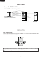
ENERGY LABEL
Usage of "the ENERGY LABEL"
When displaying this refrigerator in the shop-window, attach the
"ENERGY LABEL" to it in the following procedure.
Fix the data part of
"ENERGY LABEL (DATA)"
on the data part of
"ENERGY LABEL (BASE)"
E
A
B
C
D
E
F
G
"ENERGY LABEL (DATA)"
(This label is in Operation manual)
Data part
"ENERGY LABEL (BASE)"
of each language
Refrigerator
INSTALLATION
Free standing type
To ensure adequate ventilation for this refrigerator, install with 6 cm space at the rear and both sides, with a
minimum space of 9 cm above the refrigerator.
9cm
6cm
6cm
This refrigerator shall be used under the ordinary place condition between +5˚C and +38˚C of ambient
temperature, and also not be left under -10˚C for long days.
To be used this refrigerator within the range of the rated voltage+6%
2
SJ-P43N/43N
SJ-P47N/47N
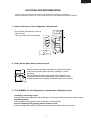
CAUTIONS AND INFORMATIONS
In case of following troubles, the cause is not related with the failure of refrigerator.
Please mention the correct way to the customer for the use of refrigerator when the repairing.
1. Some foods froze in the refrigerator compartment.
Do not place food directly in front of
cold air outlet.
This may lead to the food freezing.
cold air flow
IN
OUT
2. Some plastic parts were cracked or split.
Some household cleaning chemicals may affect the internal
food liner and plastic parts resulting in splitting or cracks
occurring.
When cleaning all plastic parts inside this refrigerator, only
use diluted dishwashing liquid(soapy water). Make sure that
all plastic parts are thoroughly rinsed with water after cleaning.
3. IT IS NORMAL for the refrigerator to produce the following sounds.
Cracking or crunching sound;
Sound produced by expansion and contraction of inner walls and internal parts during cooling.
Squeaking sound;
Sound produced by expansion and contraction of internal parts.
Sound of flowing fluid (gurgling sound, fizzing sound);
Sound of refrigerant flowing in pipes (sound may become louder from time to time).
3
SJ-P43N/43N
SJ-P47N/47N
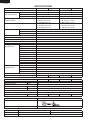
SPECIFICATIONS
Items
Type
Outer dimensions
(Including spacer)
Height
Width
Depth
Rated storage volume
(Rated volume)
Gross volume
Defrosting
System
Start
Finish
Temperature control
No-frost freezer
Interior lamp
Caster
Evaporating pan
Refrigerator
R glass shelf ass'y
Compartment
V glass shelf ass'y
Vegetable case
V parting plate
R door pocket
Egg tray
R door pocket S
Bottle pocket
Bottle stopper
Door pocket
Fresh case
Freezer
Freezer tray
Compartment
Ice cube maker
Ice storage box
Door pocket
Deodorizing unit
Plasmacluster
RATING
Items
Rated voltage
(V~)
Rated frequency
(Hz)
Climate class
Rated current
(A)
Rated input of heating elements (W)
Refrigerant (Charging quantity) [Non-flammable]
Insulation blowing gas [Flammable]
Net Weight
(kg)
PLUG TYPE
Plug cord
Plug type
Destination mark
COLOR
Items
Outside color
Inside color
SJ-P43N
SJ-43N
2-Door
1700mm(66.9")
680mm(26.8")
660mm(26.0")
347 liter (12.3cu.ft)
F: 99liter (3.5 cu.ft)
R: 248 liter(8.8 cu.ft)
370 liter (13.1cu.ft)
F: 107liter (3.8 cu.ft)
R: 263 liter(9.3 cu.ft)
Heater system
Automatic
Automatic
Automatic (Adjustable)
Yes
1
2
1
2
1
1
1
1
1
2
1
1
1
1
1
Twin ice cube maker
1
2
2 ( Honeycomb type)
Yes
No
SJ-P47N
SJ-47N
2-Door
1820mm(71.7")
680mm(26.8")
660mm(26.0")
384 liter (13.6 cu.ft)
F: 99 liter (3.5 cu.ft)
R: 285 liter(10.1 cu.ft)
407 liter (14.4 cu.ft)
F: 107 liter (3.8 cu.ft)
R: 300 liter(10.6 cu.ft)
Yes
No
SJ-P43N
SJ-43N
220-240
50
ST
1.2-1.3
128-152
HFC-134a(105g)
Cyclo pentane (HC)
70
66
SJ-P47N
SJ-47N
72
68
2 pin + Earth
CS Receptacle
E
-SL1
Silver
White
-WH1
White
4
SJ-P43N/43N
SJ-P47N/47N
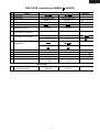
THE FICHE (according to ANNEX
NO.
1
2
3
4
5
6
: 94/2/EC)
Description
Items
Trade mark
Model name
Type
Energy efficiency class
Eco-award mark
Energy consumption
(220V 50Hz at 25 C)
Remarks
SJ-P43N,SJ-43N
Category; 7
SJ-P47N,SJ-47N
Category; 7
B
B
500
kWh/year
550
kWh/year
fridge / freezer
A++/A+/A~G
880/92
EN153
7
Net storage volume of fresh
food storage compartment
248 L
285L
8
Net storage volume of frozen
food storage compartment
88 L
88 L
11 L
11 L
4-STAR
4-STAR
2-STAR
2-STAR
No frost
9h
6.0 kg /24h
ST
No frost
9h
6.0 kg /24h
ST
39 dB(A)
re 1 pw
39 dB(A)
re 1 pw
86/594/EEC
746
kWh/year
E max
9
10
11
12
13
14
Star rating of frozen food
compartment
No frost
Temperature rise time
Freezing capacity
Climate class
Noise
at 25
at 25
(96/57/EC)
15
Maximum allowable electricity
consumption (Emax)
709
kWh/year
(1.94)
5
(2.04)
(kWh/day)
SJ-P43N/43N
SJ-P47N/47N
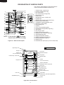
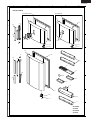
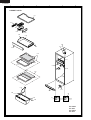
DESIGNATION OF VARIOUS PARTS
The names in parenthesis are the denominations
used in the REPLACEMENT PARTS LIST.
17
1
18
2
3
26
19
4
5
6
7
5
8
20
Plasmacluster
21
22
9
23
24
10
11
12
13
25
19
14
15
16
20
NOTE : 2 star section
for storing
frozen food only. (not freezing)
Figure D-1. External Description
1. Freezer temp. control knob
2. Freezer shelf(Freezer tray)
3. Ice cube maker
4. Ice cube box(Ice storage box)
5. Deodorizing unit
6. Fresh case
7. Refrigerator temp. control knob
8. Light(Lamp)
9. Refrigerator shelf (R grass shelf ass'y)
10. Shelf (V grass shelf ass'y)
11. Vegetable crisper(Vegetable case)
12. Divider(V parting plate)
13. Evaporating pan
14. Casters
15. Foot cover(Ventilating grille)
16. Adjustable feet(Adjustable leg ass'y)
17. Fan switch
18. Fan & light switch
19. Utility pocket(Door pocket)
20. Magnetic door seal(Door packing)
21. Egg holder(Egg tray)
22. Egg pocket(R door pocket)
23. Small pocket(R door pocket S)
24. Bottle guard(Bottle stopper)
25. Bottle pocket
26. Plasmacluster panel (Only for SJ-P43N,P47N)
Upper hinge cover
Mark: Cold air flow
Hot pipe
Fan motor
Panel P.W.B
(Only for SJ-P43N,SJ-P47N)
Freezer
compartment
Defrost thermostat
Evaporator
Freezer temp. control knob
Defrost heater
Ionizer
(Only for SJ-P43N,SJ-P47N)
Hot pipe
Refrigerator
compartment
Damper thermostat
Refrigerator temp. control knob
Drain pipe
Vegetable case
Evaporating pan
Main P.W.B
(Only for SJ-P43N,SJ-P47N)
Foot cover
Compressor
Starting relay, Overload relay(Protector)
Defrost timer
Adjustable leg ass’y
Caster
Figure D-2. Constructions
6
SJ-P43N/43N
SJ-P47N/47N
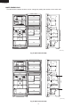
DIMENSIONS
OUTER DIMENSIONS AND CLEARANCE
more than
60
more than
680
more than
60
1
more than
60
680
73
16
1320
1022.5
1700
1260
9.5
595
90
660
470
1210
1: Not include the handle
(Unit : mm)
Fig. E-1(SJ-P43N,SJ-43N)
more than
60
more than
680
90
more than
1
60
more than
680
60
1320
1820
1260
9.5
595
470
73
16
1142.5
660
1210
1: Not include the handle
(Unit : mm)
Fig. E-2(SJ-P47N,SJ-47N)
7
SJ-P43N/43N
SJ-P47N/47N
INNER DIMENSIONS
502
89
229
The dimensions between shelves can be changed by setting the shelves on the other rails.
232
99
242
99
242
536
536
510
307
307
(172)
126
246
225
502
82
349
226
539
508.5
112
118
518
531
(172.5)
89
(133)
502
321
210
502
188
526
(Unit: mm)
502
89
229
Fig. E-3(SJ-P43N,SJ-43N)
232
99
242
510
126
539
502
225
307
307
(192)
536
99
242
82
526
349
226
536
246
628.5
112
118
518
531
(222.5)
89
(183)
502
321
210
502
188
(Unit: mm)
Fig. E-4(SJ-P47N,SJ-47N)
8
SJ-P43N/43N
SJ-P47N/47N
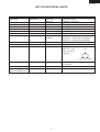
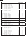
LIST OF ELECTRICAL PARTS
ITEMS
Thermostat
TYPE NAME
MM1-8149
Defrost thermostat
Thermo. fuse
Fan motor
Defrost heater
Door switch
Damper thermostat
Defrost timer
S101
SF70E
3R00121A
MM6-4264
DSD-5
MM1-6173
ND1004M2
Lamp socket
Lamp
Compressor
—
—
FL1568SD
RATING
125V 6A
250V 3A
250V 8A
250V 10A
220-240V 50/60Hz
220-240V 378Ω
250V 0.25A
—
220-240V
50/60Hz
250V 1A
240V 15W
220-240V/50Hz
SPECIFICATIONS
(At normal notch)
ON/OFF : -20 / -25˚C
Open/Close : 8 / 1˚C
Working temp. : 70˚C
Working with ø100 fan
140W at 230V
4 terminals push-button type
Open/Close : 5 / 0˚C
Integration type
Cycle time : 10h44m/8h57m(50/60Hz)
Delay time : 4m20s/3m37s(50/60Hz)
E-12(Hard plastic body type)
E-12
Cooling capacity : 188W (50Hz)
Main coil : 13.3Ω
Common
Aux. coil : 25.6Ω
(at 25˚C)
Aux. coil
Starting relay
PETOSAT
Overload relay(Protector) 1.8C36A1
Ionizer-K(Plasmacluster unit) FTRN-A014CBKZ
(Only for SJ-P43N,P47N)
—
—
DC12V
9
22 Ω 300V
3 terminals
Open/ Close : 130/60˚C
3.5kV p-p
Main coil
SJ-P43N/43N
SJ-P47N/47N
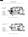
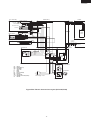
WIRING DIAGRAM
Be sure to replace the electrical parts with specified ones for maintaining the safety and performance of the set.
Defrost timer
F-Thermostat
(BR)
(GY)
(R)
CONNECTED IN
TERMINAL BOX
TM
Lamp
CONNECTOR
Source
Plug
MAIN
PWB
L
FM
: GRAY
: BROWN (live)
: ORANGE
: YELLOW
: RED
: PINK
: BLUE(neutral)
: BLACK
: SKY-BLUE
: GREEN-YELLOW (earth)
: WHITE
(W)
PC
(G-Y)
Thermo.
fuse
DOOR
PWB
(Y)
(BK)
Protector
(OR)
(SB)
GY
BR
OR
Y
R
P
BL
BK
SB
G-Y
W
Fan
motor
Defrost
heater
Door switch
Compressor
Defrost
thermo.
C
M
A
(BL)
Starting relay
PC : Plasmacluster unit
(Ionizer-K)
Figure W-1. Wiring Diagram (SJ-P43N,P47N)
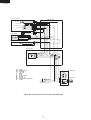
Defrost timer
(BR)
CONNECTED IN TERMINAL BOX
F-Thermostat
CONNECTOR
L
FM
Thermo.
fuse
(BK)
(Y)
Protector
Fan motor
(SB)
: GRAY
: BROWN (live)
: ORANGE
: YELLOW
: RED
: PINK
: BLUE(neutral)
: BLACK
: SKY-BLUE
: GREEN-YELLOW (earth)
: WHITE
TM
Lamp
Source
Plug
GY
BR
OR
Y
R
P
BL
BK
SB
G-Y
W
(GY)
(R)
(OR)
(W)
(G-Y)
Defrost
heater
Door switch
Compressor
Defrost
thermo.
C
M
A
(BL)
Starting relay
Figure W-2. Wiring Diagram (SJ-43N,47N)
10
SJ-P43N/43N
SJ-P47N/47N
E.V. cover ass’y
Cabinet ass’y
Lead EV-cover ass’y
Fan motor
FM
F-thermostat
Def thermo. ass’y
Fuse ass’y
F-Door
GY-1
OR-1
R-1
BR-1
Y-1
BL-1
BK-1
W-1
1
5
2
6
3
7
4
8
1
5
2
6
3
7
4
8
1
2
(W-1)
1
2 Y-2
1
2
3
1
2
3
DOOR HARNESS
1 2 3
Def. heater ass’y
CAB
HARNESS
PANEL
PWB
Door switch
2 (PUSH OPEN)
1 (NEUTRAL)
3 (PUSH CLOSE)
4 (PUSH OPEN)
1
2
3
4
BL-2
(OR-1)
SB-1
R lamp box ass’y
Lamp
15W
1
2
L
Lamp socket
1
2
BR-2
(SB-1)
1
2
Terminal box
Terminal box B
CLUSTER
HARNESS PU
ORANGE
1
2
3
4
TM
1
2
3
4
(Y-1)
(Y-2)
(BK-1)
(R-1)
GY-2
BROWN
BLUE
1
2
3
GRAY
Defrost timer
EARTH
OR-4 1
BR-6 2
BL-3
GY-3 3
4
PWB
HARNESS
MAIN
PWB
1
2
Overload relay Terminal block
(Protector)
GY
BR
OR
Y
R
P
BL
BK
SB
G-Y
W
: GRAY
: BROWN (live)
: ORANGE
: YELLOW
: RED
: PINK
: BLUE (neutral)
: BLACK
: SKY-BLUE
: GREEN-YELLOW (earth)
: WHITE
1
Compressor
E
C
M
A
BL
Source plug / cord
Starting
relay
Figure W-3. Electric Accessories Layout (SJ-P43N,P47N)
11
CLUSTER
HARNESS
1
1
2
2
1
2
Plasmacluster unit
(Ionizer-K)
SJ-P43N/43N
SJ-P47N/47N
E.V. cover ass’y
Cabinet ass’y
Lead EV-cover ass’y
Fan motor
FM
F-thermostat
Def thermo. ass’y
Fuse ass’y
Def. heater ass’y
GY-1
OR-1
R-1
BR-1
Y-1
BL-1
BK-1
W-1
1
5
2
6
3
7
4
8
1
5
2
6
3
7
4
8
1
2
(W-1)
1
2 Y-2
Door switch
2 (PUSH OPEN)
1 (NEUTRAL)
3 (PUSH CLOSE)
4 (PUSH OPEN)
1
2
3
4
BL-2
(OR-1)
SB-1
R lamp box ass’y
Lamp
15W
L
Lamp socket
1
2
1
2
BR-2
(SB-1)
Terminal box
TM
1
2
3
4
1
2
3
4
(Y-1)
(Y-2)
(BK-1)
(R-1)
GY-2
BLUE
GRAY
EARTH
Defrost timer
GY
BR
OR
Y
R
P
BL
BK
SB
G-Y
W
BROWN
: GRAY
: BROWN (live)
: ORANGE
: YELLOW
: RED
: PINK
: BLUE (neutral)
: BLACK
: SKY-BLUE
: GREEN-YELLOW (earth)
: WHITE
Overload relay Terminal block
(Protector)
1
Compressor
E
C
M
A
BL
Source plug / cord
Starting
relay
Figure W-4. Electric Accessories Layout (SJ-43N,47N)
12
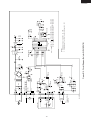
13
LED1
ZD1
PC
R21
(1/2W)
680
SW
CN4
2
3
1
CN2
CN3
(MAIN PWB)
PC :
PLASMACLUSTER UNIT
(IONIZER-K)
(PANEL PWB)
F-FM
CN1
2
1
2
3
1
1
7
3
5
R17
(1/2W)
1.8
R11
1K
R1
R2
VRS1
C15
100
10V
R18
10K
C13
0.1
Q3
KTA1046
TRNS
C10
1
50V
C9
0.1
D7
ISS270A
Q1
KRA101M
C3
0.1
50V
C7
0.1
R7
1K
(A/D)
13
C2
2200
35V
10
RS2
RS3
4.7K R20
RS1
R8
10K
R19
OPEN
I
IC1
C16
0.1
O
I
C19
1000
25V
11
IC2
O
G
C18
0.1
7805
C5
1
50V
C20
100
10V
PST993E
IC3
3
1
2
C6
0.1
C4
0.1
RS1,2,3=43K(1/2W), RS3=OPEN,
VRS1,2=560V
RS1,2,3=18K(1/2W), RS3=10K(1/8W), VRS1,2=270V
RS1,2,3=18K(1/2W), RS3=SHORT,
VRS1,2=270V
CST4.00MGW
1M R6
C8
0.1
CF1
C17
100
10V
12 5V
[ NOTE ]
1. Resistance which is not specified : 5% 1/8W
2. Rated voltage of the condenser which is not specified : 25V
220 240V
120V
110 120V
TMP47C241N
IC4
VDD
VAREF
R40(AINO) K03
K02
R41(AIN1)
K01
R42(AIN2)
K00
R43(AIN3)
R71(WT0) HOLD
R80(INT2) RESET
XOU
R81(T2)
XIN
R82(INT1)
TEST
P10
R92
P11
R91
P12
R90
P13
P20
VSS
INPUT VOLTAGE
C12
0.1
G
7812
12V
Figure W-5. Circuit Diagram (Only for SJ-P43N,P47N)
R14
1K
R5
2.2K
R4
10K
D3
Q6
KRA101M
D4
D6
IN4005E
D5
PC1
PC123
Q2
KRC101M
R15
4.7K
R13
4.7K
12V
R9
1K
Q7
KRA101M
D2
ISS270A
R3
Q4
KRC101M
R10
2.2K
Q5
KRA101M
C11
0.1
2A
VRS2
12V
R16
10K
9
8
7
6
5
C1
0.1
250V
2A
D1
IN4007E
R12
2.2K
4
3
2
1
HS
SJ-P43N/43N
SJ-P47N/47N
SJ-P43N/43N
SJ-P47N/47N
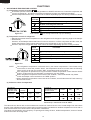
FUNCTIONS
1. ADJUSTABLE TEMPERATURE CONTROL
(1) Temperature control of freezer
Thermostat (senses freezer temperature) operates on ON/OFF switchover to control the compressor and
cool air circulating fan , and allows the freezer temperature to keep at a suitable temperature.
However adjust the freezer temp. control knob as follows depending upon the storing condition of foods.
PURPOSE
KNOB
SETTING
MAX(Coldest)
For making ice rapidly or fast freezing.
When restocking with fresh food.
MED
For normal freezing.
For storing frozen food for a short period (up to one month).
When frozen food or ice cream is not stored.
MIN
Figure F-1.
2 star section
for storing frozen food only.(not freezing)
(2) Temperature control of refrigerator
Damper-thermostat senses temperature of the refrigerator and changes the opening angle of the damper
automatically.
However, as the Damper-thermostat has no function to switch on or off the compressor and fan motor, the
freezer temperature control causes temperature in the refrigerator to vary to some extent.
However, adjust the refrigerator temp. control knob as follows depending upon the cooling condition.
PURPOSE
KNOB
SETTING
Coldest
For keeping freshness of food longer.
When the refrigerator does not provide sufficient cooling.
MED
For normal operation.
When the refrigerator provides excessive cooling.
MIN
Figure F-2.
NOTE:
The refrigerator temperature is affected also by the freezer temperature. If the freezer temp.
control knob is set at the position "MAX", the temperature tends to be lower than the following
values, and if set at near the position "MIN", temperature tends to be higher.
If the refrigerator is operated for a long time with the freezer temperature control sets the "MAX"
position, foods stored in the refrigerator compartment may also freeze.
When refrigerator temperature control sets to the "Coldest", some foods stored may freeze.
In this case adjust control set back to the "MED" position.
When refrigerator temperature control sets to the "Coldest", some foods stored in Fresh case may
also become frozen.
(3) Reference value of temperature
SETTING OF
FREEZER TEMP.
CONTROL KNOB
MAX
(Coldest)
MED
MIN
Freezer
temperature
Approx.
-21 C
Approx.
-18 C
2 star section
temperature
-15 C
-12 C
SETTING OF
REFRIGERATOR TEMP.
CONTROL KNOB
Coldest
MED
MIN
Approx.
-15 C
Refrigerator
temperature
Approx.
0
Approx.
3
Approx.
6
-9 C
Fresh case
temperature
Approx.
-3
Approx.
1
Approx.
4
The values shown above refer to the case where the
freezer temp. control knob is set at "MED".
The values shown above refer to the measurement carried out center area and 1/3 of overall height from the bottom
at each of the refrigerator and the freezer after machine has been operated at an ambient temperature of 30˚C with no
food stored and the door closed until the temperature is stabilized.
The values vary depending upon frequency of opening and closing the door, ambient temperature, amount of stored
foods and manner of storing foods.
14
SJ-P43N/43N
SJ-P47N/47N
2. DEFROSTING
(1) No defrosting operation is necessary
No defrosting operation is necessary.
As this machine is so designed that a built-in
evaporator cools air and a fan circulates cooled
air, neither the freezer nor the refrigerator is
frosted, though the evaporator is frosted.
The frosted evaporator is defrosted automatically
due to the function of defrosting timer and heater,
requiring no defrosting operation.
(2) Where is melted frost brought
1. Melted frost is brought into the evaporating
pan at the back of the set and is evaporated
here by the heat of compressor.
2. Be sure to use Evaporating pan as inserted
so as to be level with the outer case.
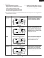
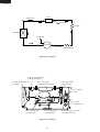
(3) The following circuit diagrams in the table show automatic defrosting function of the refrigerator with
timer and defrost thermostat.
Operation
1. Cooling
(Normal)
Electric diagram
Defrost thermostat ON
Compressor running
Timer motor running
Thermo. fuse
Defrost heater
TM
Defrost
thermostat (ON)
COMP
Compressor
Timer contact
Timer motor
SOURCE
Thermostat
Description
The integration timer integrates running
time of the compressor. When it reaches
cycle time of defrost timer, the timer
contact is changed to start defrosting.
Figure F-3.
Defrost thermostat ON
(Time 20 to 30 min.)
Thermo. fuse
Defrost heater
TM
Defrost
thermostat (ON)
COMP
Compressor
Thermostat
SOURCE
Compressor stops
Timer motor stops
Timer contact
Timer motor
2. Defrosting
The timer contact is changed to start
defrosting, the timer motor stops, and
power is supplied to the defrost heater.
It takes about 20 to 30 min. to defrost.
When little frosted, the defrosting takes
little time. When much frosted, the defrosting takes much time.
Figure F-4 .
Defrost thermostat OFF
Thermo. fuse
Defrost heater
TM
Defrost
thermostat (OFF)
COMP
Compressor
Thermostat
SOURCE
Compressor stops
Timer motor running
Timer contact
(Time approx. 5 min.)
Timer motor
3. Drain
When the defrost thermostat becomes
OFF, the timer motor starts running.
During the operation time (delay time
of defrost time) defrosted water is
drained outside the refrigerator.
Figure F-5.
Defrost thermostat OFF
SOURCE
Thermostat
Compressor running
Timer motor stops
Timer contact
Thermo. fuse
Defrost heater
TM
Defrost
thermostat (OFF)
Figure F-6.
15
COMP
Compressor
(Time approx. 5 min.)
Timer motor
4. Restart
Timer contact is changed to cooling
operation and the compressor starts
running and the timer motor stops.
Defrost thermostat contact becomes ON
when it’s cooled. And the timer motor
starts running. (Figure F-3.)
SJ-P43N/43N
SJ-P47N/47N
(4) As a reference to determine the causes of trouble, malfunction and phenomena are described below.
Refer to the following when repairing.
1. Disconnection of defrost heater
As off-cycle defrosting is performed, the defrosting time is extremely prolonged. Each time defrosting is
started, the freezer temperature rises and a portion of ice and stored foods are melted.
2. Melted thermo. fuse or opened-circuit due to the defect of defrost thermostat.
When the above mentioned trouble occurs in cooling operation, the timer motor does not run, defrosting
will not take place, and consequently freezing is caused. In the above mentioned condition, when the timer
shaft is turned by hand to defrost, the timer motor runs during the operation time. However, the motor stops
from the time when the contact is changed, and freezing causes.
NOTE:
As the thermo. fuse assembly is intended to prevent dangers, do not use it under shorted condition even
for a short period.
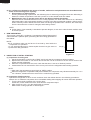
3. DEW PREVENTION
The hot pipe, namely D.P.-condenser, is arranged around the flange part of
cabinet and the C-partition plate, preventing dew from being generated on
the cabinet.
NOTE:
D.P.-condenser pipe may be felt hot if touched by hand while the
compressor is in operation.
If you are asked about this, please explain that the hot pipe serve to
prevent the dew generation.
Hot pipe
Figure F-7
4. INSPECTION OF INITIAL STARTING
(1) Inspection of cooling unit
1. Set the temperature control knob to "MAX" and check that the compressor starts to operate.
2. Depress the door switch to run the fan and check that cool air is blown out of the cold air outlet of the
freezer and the refrigerator.
3. When the compressor does not work, check that the timer is not set to "defrost" position.
4 It takes about an hour and a half or two hours to put food in the refrigerator after starting operation.
NOTE:
After return the temperature control knob to "MED" position.
When the refrigerator is operated initially after installed, the compressor may vibrate excessively for 1 to 2
min. However, vibration becomes normal if it is continuously operated.
(2) Inspection of defrost device
Operate the refrigerator for 20 to 30 min. and then check the defrost device in the following procedures :
Allow 5 min. to restart the compressor since immediate starting after stopping will cause unsmooth operation.
1. Turn the timer shaft clockwise with a screw driver.
At this time, make certains the timer clinks and the compressor stops.
2. After more than 5 min., turn the shaft further to operate.
Make certain cooling operation is started again.
16
SJ-P43N/43N
SJ-P47N/47N
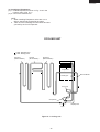
5. PLASMACLUSTER (Only for SJ-P43N,P47N)
(1) Plasmacluster is what thing.
The ionizer inside the refrigerator will release cluster ions, which are collective mass of positive and negative
ions, into the the freezer and refrigertor compartments.
The cluster ions inactivate airborne fungus.
(2) Plasmacluster Panel
1.When the refrigerator will be operated, the Plasmacluster lamp of the
panel will light up.
2.By pushing the button, the lamp goes out or lights up.
3.Under the lamp is lighting, Plasmacluster operation is controlled as
follows.
Plasmacluster panel
Lamp
Plasmacluster
Button
(3) Plasmacluster Control.
1.Plasmacluster operation will be performed when the following conditions
gather.
1) Lamp : Under lighting
2) Compressor : Under operation
3) Door : Closed
4) Within "The Plasmacluster operation time".
2.If the sum total of Plasmacluster operation time will reach at the set time ("The Plasmacluster operation Time") ,
Plasmacluster operation will stop.
3.After an operation stop, the Plasmacluster will be not operated during the set time ("The Plasmacluster operation
compulsive stop time") .
Time chart A
Compressor ON
Fan motor Door
Plasmacluster t1
t2
t3
Time chart B
Compressor
Fan motor Door
Plasmacluster t1
t2
t3
The Plasmacluster operation time = t1 + t2 + t3
17
SJ-P43N/43N
SJ-P47N/47N
ASSEMBLING PROCEDURES OF MAIN PARTS AND CAUTIONS
CAUTION: DISCONNECT THE UNIT FROM THE POWER SUPPLY BEFORE ANY REPAIRING.
1. R-AIR GUIDER ASSEMBLY
A-sealer ag1
Damper thermo.
Thermo. cap. sealer
R air guider S
Plasma holder
(Only for SJ-43N,SJ-47N)
A-sealer ag3
Ionizer-K
A-sealer ag2
Dial sealer
Plasma harness
(Only for SJ-P43N,SJ-P47N)
R air guider
Figure A-1
Less than 160 mm
(1) Forming sensor of Damper thermo.
Less than 12 mm
8 +1 mm
5 +1 mm
Damper
thermostat
NOTE
Minimum bending radius is R5mm.
There should be no gas leak by reforming of sensor tube.
After forming, fix it to the refrigerator.
Figure A-2
(2) Setting R air guider S (Only for SJ-43N,SJ-47N) and sticking sealers to R air guider.
R air guider S
(Only for SJ-43N,47N)
A-sealer ag1
R air guider
A-sealer ag1
Masking tape
OVERLAP 15mm
R air guider
A-sealer ag2
A-sealer ag1
A-sealer ag2
Dial sealer
A-sealer ag1
Figure A-3
18
A-sealer ag3
OVERLAP AREA
DATUM
DATUM
OVERLAP 8mm
OVERLAP 15mm
DATUM
SJ-P43N/43N
SJ-P47N/47N
(3) Fixing of the Ionizer-K.(Only for SJ-P43N,P47N)
(3)-1 Connect Ionizer-K and connector of the lead wire.
(3)-2 Insert Ionizer-K to Plasma holder.
(3)-3 Insert the (3)-2 assembly to R air guider A.
R air guider A
Plasma harness
Ionizer-K
2P
Connector should insert surely.
Plasma harness
Plasma holder
Ionizer-K
A
Paper tape W30×100mm
B
B
Paper tape W30×40mm
2P
2P
2P
A
SEC. A—A
Paper tape W30×40mm
SEC. B—B
19
SJ-P43N/43N
SJ-P47N/47N
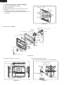
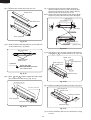
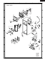
2. FAN LOUVER AND E.V COVER ASSEMBLY
2-1. How to remove the Fan louver
(1) Take out 2 screws.
(2) Insert the screwdriver into the air hole of the Fan
louver.
(3) Press the Fan louver to the left side with the
screwdriver,and pull it toward yourself to take off the
Fan louver.
(4)
Fan louver
Claw
(4)
Claw
(1)
Screw
(4)
Claw
(3)
(3)
Claw
(1)
Screw
(2)
Figure A-4
2-2. E.v cover assembly
Motor cushion
Fan motor holder B
Fan motor
holder A
E.v cover sealer C
Defrost thermo.
ass’y
L-band C
E.v cover
Propeller fan
100
Fan motor
Fan clamp
U-sealer
handle
E.v cover
sealer G
Lead EV-cover
ass’y
E.v cover
sealer F
E.v cover
sealer C
E.v cover
sealer A
E.v cover
AL A
L-band C
E.v cover
sealer B
F-thermostat
Fuse ass’y
E.v cover sealer E
E.v cover sealer D
Figure A-5
(1) Sticking of Sealers to E.V cover
(2) Fixing of Fan motor and Fan
(2)-1 Stick U-sealer handle to Fan motor holder A.
Fan motor holder A
E.v cover sealer A
C
7 + 2mm
E.v cover sealer C
STICK START
STICK START
E.v cover
0 + 1mm
E.v cover sealer G
U-sealer handle
STICK START
E.v cover sealer B
SEC. C-C
[back side]
Figure A-7
Figure A-6
20
C
U-sealer handle
SJ-P43N/43N
SJ-P47N/47N
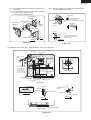
(2)-2 Insert the terminals of Lead EV-cover ass'y to
Fan motor.
(2)-3 Fix two Motor cushions to Fan motor, and set it
at Fan motor holder A and B.
Then fix with Tapping screw.
(2)-4 Set Fan clamp to Propeller fan 100 and insert
it to the shaft of Fan motor.
Fan clamp
Fan motor
holder B
D
Fan clamp
Motor cushion
Fan motor
holder A
Slit of each Fan clamp
and Propeller fan
should not be at same position.
Slit
Fan clamp
Propeller
fan 100
Tapping
screw
Propeller fan
Fan motor
○
×
4 + 0.5mm
Note
Propeller fan should not be
taken out from shaft when
pulled by 3 kgf.
Shaft
Lead EV-cover ass’y
RED
Detail of D
BROWN
Figure A-8
Figure A-9
(3) Setting of Fan motor ass'y , Defrost thermo. ass'y and Fuse ass'y.
E.v cover
Lead e.v cover
ass’y
Tapping screw
L-band C
more than 3.5mm
more than 3.5mm
Aluminum tape
L-band C
F
E.v cover sealer C
Take out lead wire
from square hole to
front and fix with
L-band C, then seal
with E.v cover sealer C
F
Tapping screw
Set metal side below
[front side]
Defrost thermo.
ass’y
H
Aluminum tape
E.v cover sealer F
G
H
Fuse ass’y
E.v cover AL A
Aluminum tape
Turn up lead wire
CUT
Fuse ass’y
ATTENTION
Defrost thermo.
ass’y
E.v cover
sealer E
10 + 5mm
[back side]
Aluminum tape
L-band C
Detail of G
Not come out of claw.
SEC. F F
SEC. H H
E.v cover sealer E
[Front side]
Figure A-10
21
SJ-P43N/43N
SJ-P47N/47N
(4) Inserting of pins
After inserting, fix with vinyl tape.
F-thermostat 2
(RED, inserted)
Defrost thermo. 3 (PINK)
Fuse 8 (WHITE)
Fan motor 1 , 5
WIRE COLOR FOR FAN MOTOR
100-110V : WHITE
127V : YELLOW
220-240V : BLUE
1
2
3
4
5
6
7
8
F-thermostat 6
(BROWN, inserted)
Vinyl tape
Fuse 8 (BLACK)
Defrost thermo. 7 (BLUE)
Note
Pins should be inserted surely,
and check by pulling it.
Figure A-11
Figure A-12
(5) Setting of F-thermostat
(5)-3 Set to E.V cover.
Stick E.v cover sealer D.
(5)-1 Form capillary tube of F-thermostat.
E.v cover sealer D
21mm
B
R10mm
R10mm
Note
F-thermostat
• Bending radius of
capillary tube should be
from R5mm to R10mm.
8.5mm
50mm
Figure A-13
(5)-2 Insert terminal of Lead EV-cover ass'y.
B
SEC. B B
RED
(front side)
BROWN
Figure A-15
(back side)
Figure A-14
22
SJ-P43N/43N
SJ-P47N/47N
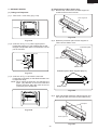
(2) Replacement of Def. heater ass'y.
(2)-1 Remove the center screw of Drain support al
to take it off from the food liner.
3. DEFROST HEATER
(1) Taking-out Evaporator
(1)-1. Take out E.v cover ass'y (Fig. A-16).
Drain support al
Evaporator
Screw
Food liner convex part
Fig. A-19
Fig. A-16
(2)-2 Raise the protrusion part of Drain support al.
Then remove Heater cover.
(1)-2. As shown in Fig. A-17, pull the upper part of
Evaporator toward you, pull it diagonally so that
the pipe of Evaporator does not contact the convex
part of food liner.
Protrusion parts
Food liner convex part
Drain support al
Evaporator
Pipe
Heater cover
Protrusion part of Drain support al(2 pcs.)
Fig. A-17
(1)-3. As shown in Fig. A-18, bend the removed
Evaporator horizontally so that Defrost heater can
be replaced easily.
NOTE: When pulling Evaporator and bending the
pipes, pay attention so as not to break and
deform the pipes. Still, take care not to hurt
yourself by fin of Evaporator.
Def. heater ass’y
Heater cover
Fig. A-20
(2)-3 Open Def.heater fixed part of Drain support al to
the right and left, then remove Def.heater ass'y.
Evaporator
Fixed parts
Fig. A-18
Drain support al
Def.heater ass’y
Fig. A-21
23
SJ-P43N/43N
SJ-P47N/47N
(2)-4. Replace Def. heater ass'y with new one.
(2)-7. Stick the longer wire to the Drain support by
aluminum tape (2 pieces), and wind vinyl tape
(2 pieces) to lead wires of Def. heater ass'y by
aluminum tape as shown in Fig. A-25.
Note: Glass cloth tape part shall be both side of Drain
support to protect the lead wire from damaged.
Heater cover
Glass cloth tape
Glass cloth tape
Def.heater ass’y
A
A
Sec. AA
[back side]
aluminum tape
(W25 X L40)
Drain support al
Fig. A-22
Glass cloth tape
Glass cloth tape
(2)-5. Wind the Glass cloth tape (3M: No. 27) to lead wire
of Def. heater ass'y. (2 places)
(more than 2 turns)
[bottom side]
Fig. A-25
Def. heater ass’y
360 + 5
(2)-8. Set Heater cover on Drain support, and bend top
edge c and d to outside as shown in Fig. A-26.
(40)
(40) 50 + 5
Heater cover
top edge
Glass cloth tape
(W40 x L25)
Def.heater ass’y
Drain support al
Lead wire
Heater cover
Glass cloth tape
Wind the Glass cloth tape
more than 2 turns.
c
Sec. BB
Fig. A-23
B
d
(2)-6. Bend a and b of Drain support al to right angle
(90˚) to set Def. heater ass'y. (Fig. A-24)
Def.heater ass’y
B
Fig. A-26
This side is longer wire
(2)-9. Wind up Leading wire sealer as shown in Fig. A-27
a
This side is shorter wire
Drain support al
Heater cover
Leading wire sealer
Drain support al
0
19
Def.heater ass’y
0
+2
b
Def.heater ass’y
Fig. A-24
Fig. A-27
(2)-10. Set the assembly above on the food liner by fixing
a screw.
24
SJ-P43N/43N
SJ-P47N/47N
(3) Installing of Evaporator
(3)-1. Install Evaporator as shown in Fig. A-16 in the
reverse order of Fig. A-17.
(3)-2. Correct the deformed fin.
NOTE
1. When installing Evaporator, take care not to
deform significantly and break the pipes.
2. Take care not to damage the lead wires and hurt
yourself by the fin of Evaporator.
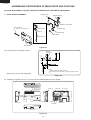
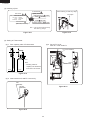
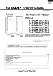
COOLING UNIT
Mark: Refrigerant flow
Mark: Brazing portion
Hot pipe L
(Side condenser)
Hot pipe
(DP-condenser)
Hot pipe R
(Side condenser)
Evaporator
Back condenser
Suction pipe
Eva-pan pipe
Compressor
Capillary tube
Dryer
Figure C-1. Cooling unit
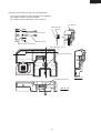
25
SJ-P43N/43N
SJ-P47N/47N
Dryer
Capillary tube
Charge pipe
Hot pipe
Evaporator
Charge pipe
Compressor
Suction pipe
S.P. connector
Eva-pan pipe
Back condenser
Figure C-2. Location
From Eva-pan pipe ass’y
to Back condenser In
From Back condenser out
to Hot pipe
From Compressor
to Discharge p connector
From Suction pipe
to SP connector
From Hot pipe
to Dryer
From Dryer
to Capillary tube
From SP connector
to Compressor
From Compressor
to Charge pipe
Figure C-3. Location
26
From Discharge p connector
to Eva-pan pipe ass’y
SJ-P43N/43N
SJ-P47N/47N
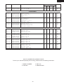
REPLACEMENT PARTS LIST(SJ-P43N/43N-SL1/WH1)
REF. NO.
PART NO.
DESCRIPTION
Q'TY
CODE
SJ-P43N SJ-P43N SJ-43N
-SL1
-WH1
-SL1
SJ-43N
-WH1
ELECTRIC PARTS
11111111111111111111-
1
2
3
4
5
6
7
8
9
10
11
17
20
21
22
33
45
46
50
55
RTHM-A103CBZZ
RSTT-A134CBE0
QSWTDA047CBZZ
PDMP-A050CBEZ
FTHM-A039CBKZ
RMOTRA046CBE0
QSOCAA084CBEZ
RLMP-A029CBEZ
QACC-A156CBZZ
QSW-PA090CBZA
RHOG-A161CBZZ
FFS-TA061CBKZ
FW-VZA146CBEZ
FHETBA161CBEZ
FCNW-A733CBKZ
QCNW-A886CBE0
FTRN-A014CBKZ
QCNW-B104CBZZ
FPWB-A337CBKZ
FPWB-A336CBKZ
F-themostat
Starting relay
Defrost timer
Damper thermo
Defrost thermo.ass’y
Fan motor
Lamp socket
Lamp15w
Source cord
Door switch
Protector
Fuse ass’y
Lead ev-cover ass’y
Def.heater ass’y
Relay wire ass’y
Olr cord
Ionaizer-k
Plasma harness
Main pwb
Panel pwb ass’y
222222222222222222222222222222222222222222222222222-
2
4
7
7- 1
7- 2
8
8- 2
13
14
15
16
17
19
20
21
22
23
24
26
27
28
29
29
29
31
38
38
39
43
44
45
46
47
49
50
55
56
57
63
64
65
66
67
68
69
70
71
72
73
77
78
JKNB-A036CBFC
LANG-A059CBPZ
FLEGPA083CBKZ
FAJS-A015CBKZ
LHLD-A533CBPZ
FLEGPA084CBKZ
LHLD-A534CBPZ
DHNG-A437CBMZ
DHNG-A419CBMZ
DHNG-A418CBMZ
GCOV-A210CBFZ
LCRA-A022CBPZ
LHLD-A389CBF0
NFANPA011CBF0
PSEL-C067CBEZ
PSEL-C068CBEZ
PSEL-C066CBEZ
PCOVPA308CBFA
PCOV-A277CBFA
GCOVPA142CBRA
HGRL-A206CBRA
GCOV-A228CBFA
GCOV-A228CBFF
GCOV-A228CBFH
JKNB-A033CBFC
PGID-A161CBFZ
PGID-A168CBFZ
PGID-A162CBFZ
LPLTPA323CBMA
HGRL-A237CBFA
HGRL-A238CBFA
PFIL-A050CBEZ
LHLD-A672CBFZ
LSTPPA108CBFA
LSTPPA118CBFA
HGRL-A209CBFA
PFPFPB345CBFZ
PSEL-C095CBEZ
LHLD-A484CBFA
LHLD-A485CBFA
PSEL-B209CBE0
PSHEMA225CBPZ
LPLTMA633CBPZ
PSEL-A415CBE0
PSEL-C069CBEZ
PSEL-C135CBEZ
PSEL-A552CBE0
PSEL-C078CBEZ
PSEL-C079CBEZ
LHLD-A391CBE0
LPLTMA399CBP0
F-temp. control knob
Eva holder 47
Leg holder l ass’y
Adjustable leg ass’y
Leg holder l
Leg holder r ass’y
Leg holder r
Upper hinge ass’y
Bottom hinge r ass’y
Center hinge r ass’y
E.v cover
Fan clamp
Motor cushion
Propeller fan 100
E.v cover sealer a
E.v cover sealer b
E.v cover sealer c
Terminal cover
R lamp cover
R-c box cover
Fan louver
Upper hinge cover
Upper hinge cover
Upper hinge cover
R-temp.control knob
R-air guider
R-air guider
R-air guider s
Panel base
F deodo.louver
R deodo.louver
Deodorizer
Plasma holder
Chilled stopper
Case stopper v
Multi louver s
R-louver insu.s
A-sealer r-louver
Fan motor holder b
Fan motor holder a
U-sealer handle
Heater cover
Drain support al
E.v cover sealer c
E.v cover sealer d
E.v cover sealer e
Dial sealer
A-sealer ag1
A-sealer ag2
Sl-5n clip
Dryer support
1
1
1
1
1
1
1
1
1
1
1
1
1
1
1
1
1
1
1
1
1
1
1
1
1
1
1
1
1
1
1
1
1
1
1
1
1
1
1
1
1
1
1
1
1
1
1
1
1
1
1
1
1
1
1
1
-
1
1
1
1
1
1
1
1
1
1
1
1
1
1
1
1
-
AV
AS
AZ
AW
AM
AZ
AL
AH
AQ
AS
AX
AM
AL
AY
AP
AE
AZ
AF
BC
AT
1
2
1
2
1
1
1
1
1
1
1
1
2
1
1
1
1
1
1
1
1
1
1
1
1
1
1
2
1
2
2
1
1
2
1
1
2
1
1
1
1
1
1
2
1
1
1
1
2
1
2
1
1
1
1
1
1
1
1
2
1
1
1
1
1
1
1
1
1
1
1
1
1
1
2
1
2
2
1
1
2
1
1
2
1
1
1
1
1
1
2
1
1
1
1
2
1
2
1
1
1
1
1
1
1
1
2
1
1
1
1
1
1
1
1
1
1
1
1
1
1
2
2
2
1
1
2
1
1
2
1
1
1
1
1
1
2
1
1
1
1
2
1
2
1
1
1
1
1
1
1
1
2
1
1
1
1
1
1
1
1
1
1
1
1
1
1
2
2
2
1
1
2
1
1
2
1
1
1
1
1
1
2
1
1
1
AC
AC
AF
AE
AL
AF
AP
AE
AD
AE
AR
AC
AF
AD
AA
AA
AC
AE
AE
AQ
AS
AE
AF
AE
AC
AG
AK
AC
AN
AE
AC
AM
AE
AC
AC
AM
AE
AB
AH
AH
AB
AC
AF
AC
AA
AC
AC
AC
AB
AD
AD
MECHANICAL PARTS
27
SJ-P43N/43N
SJ-P47N/47N
REF. NO.
PART NO.
DESCRIPTION
Q'TY
CODE
SJ-P43N SJ-P43N SJ-43N
-SL1
-WH1
-SL1
2222222222222-
79
80
81
82
83
87
91
93
94
95
99
100
101
LBND-A019CBE0
PBOX-A132CBFA
PBOX-A143CBFA
PCOVPA373CBFA
PSEL-C080CBEZ
LBND-A018CBE0
HGRL-A202CBFA
PCAP-A068CBFA
PSEL-C137CBEZ
PSHEMA231CBEZ
PSEL-A562CBE0
PSEL-C138CBEZ
PSEL-C139CBEZ
Nylon band
Terminal box
Terminal box-b
Terminal cover-b
A-sealer ag3
Fastening band a
F return cover
C sliding cap a
E.v cover sealer f
Ev cover al a
Leading wire sealer
E.v cover sealer g
Ev-insulation 47
SJ-43N
-WH1
1
1
1
1
1
1
1
4
1
1
1
1
2
1
1
1
1
1
1
1
4
1
1
1
1
2
1
1
1
1
1
4
1
1
1
1
2
1
1
1
1
1
4
1
1
1
1
2
AB
AF
AH
AN
AA
AP
AF
AC
AB
AC
AC
AA
AC
1
1
1
1
2
1
1
1
1
1
1
1
1
1
1
1
1
1
1
1
1
1
1
1
2
1
1
1
1
1
1
1
1
1
1
1
1
1
1
1
1
1
1
1
1
1
1
2
1
1
1
1
1
1
1
1
1
1
1
1
1
-
1
1
1
1
1
1
2
1
1
1
1
1
1
1
1
1
1
1
1
1
-
BS
BS
BS
BU
AD
AC
AD
AK
AN
AN
AT
AH
AN
AD
AH
AM
BU
BT
BS
BS
AD
AC
AF
AV
AN
AP
AD
AK
BA
AH
4
8
8
1
4
4
8
8
1
4
4
8
2
1
1
4
4
8
2
1
1
4
AC
AC
AH
AH
AC
AB
1
2
3
1
1
1
1
1
1
1
1
1
1
1
2
2
2
1
1
1
1
2
3
1
1
1
1
1
1
1
1
1
1
1
2
2
2
1
1
1
1
2
3
1
1
1
1
1
1
1
1
1
1
1
2
2
2
1
1
1
1
2
3
1
1
1
1
1
1
1
1
1
1
1
2
2
2
1
1
1
AR
AH
AM
AL
AH
AS
AT
AN
AN
AM
AG
AX
AL
AV
AN
AR
AU
AS
AR
AW
AS
DOOR PARTS
333333333333333333333333333333-
5
5
5
5
5- 1
5- 2
5- 3
5- 4
5- 5
5- 5
6
7
8
9
10
11
15
15
15
15
15- 1
15- 2
15- 3
17
19
20
21
22
30
31
FDORFB832CBKZ
FDORFB833CBKZ
FDORFB847CBKZ
FDORFB848CBKZ
LSTPPA131CBFA
NBRGPA033CBFA
LSTPMA008CBM0
GDAI-A071CBMZ
HBDGDA946CBEA
HBDGDA946CBEC
FPACGA346CBKZ
HDECQA475CBMA
HDECQA476CBRA
LPLTMA686CBPZ
LPLTPA374CBFA
HDECQA478CBMA
FDORRB640CBKZ
FDORRB642CBKZ
FDORRB661CBKZ
FDORRB662CBKZ
LSTPPA084CBFA
NBRGPA022CBFA
LSTP-A058CBM0
FPACGA348CBKZ
HDECQA477CBRA
HDECQA479CBMA
LPLTMA687CBPZ
LPLTPA375CBFA
GCOVPA177CBRA
HBDG-A005CBEA
F-door ass’y
F-door ass’y
F-door ass’y
F-door ass’y
Fd-stopper spring r
Nylon bearing 3f
F-door stopper r
Badge base
Badge
Badge
F-door packing
Hd cap
Handle trim f
Hd support f
Handle base f
Hd cover ft
R-door ass’y
R-door ass’y
R-door ass’y
R-door ass’y
Rd-stopper spring r
Nylon bearing 3s
R-door stopper r
R-door packing
Handle trim r
Hd cover rb
Hd support r
Handle base r
Panel cover
Pc badge
444444-
1
3
11
12
15
17
LBND-A023CBE0
LX-VZA022CBZZ
QTAN-A012CBE0
QTAN-A013CBE0
LX-BZA090CBZZ
LX-WZA035CBZZ
L-band c
Special screw
Solderless term. b
Solderless term. a
Special screw
Washer
555555555555555555555-
1
2
3
4
5
6
9
13
13
14
15
16
17
18
19
24
242425
2525-
UPOK-A180CBRA
UPOKPA268CBFA
UPOK-A179CBRA
UPOK-A181CBRA
UTNA-A282CBFA
FSRA-A193CBYZ
USRA-A270CBFA
HGRL-A239CBFA
HGRL-A239CBFC
USRA-A268CBFA
GGAD-A032CBFA
UYOK-A401CBFA
UYOK-A399CBFA
UYOK-A400CBFA
GDORPA072CBRA
FTNA-A394CBKZ
UTNA-A377CBEZ
UWAKPA014CBFA
FTNA-A395CBKZ
UTNA-A378CBEZ
UWAKPA015CBFA
Bottle pocket
R door pocket s
Door pocket
R door pocket
Egg tray
Ice cube maker
Freezer tray
Ventilating grille
Ventilating grille
Evaporating pan
V parting plate
Vegetable case
Ice storage box
Fresh case
Fresh door hs
R glass shelf ass’y
Glass shelf r
G guard r
V glass shelf ass’y
Glass shelf v
G guard v
OTHER PARTS
ATTACHMENT PARTS
1
2
1
2
28
SJ-P43N/43N
SJ-P47N/47N
REF. NO.
PART NO.
DESCRIPTION
Q'TY
CODE
SJ-P43N SJ-P43N SJ-43N
-SL1
-WH1
-SL1
5- 31
5- 32
5- 35
LRALPA136CBFA
LRALPA137CBFA
UPOKPA269CBFA
Ice tray holder l
Ice tray holder r
Bottle stopper
666666666666666-
PCMPLA215CBEZ
PSPAGA042CBE0
FFRM-A120CBKZ
FDRY-A006CBK0
PCLI-A050CBE0
PSPAFA034CBE0
PPIPCA386CBEZ
PPIPCA252CBE0
FPIPCA172CBKZ
PCOVPA246CBE0
PGUM-A004CBF0
QTAN-A045CBE0
FPIPCA162CBKZ
LANG-A058CBPZ
PGUM-A003CBF0
Compressor
Rubber grommet
Base frame ass’y
Dryer ass’y
Clip
Sleeve
S.p connector
Charge pipe
Discharge p. ass’y
Terminal cover
Absorbent rubber a
Terminal block
Eva pan pipe s ass’y
Absorbent rubber clm
Absorbent rubber b
TINS-A684CBRZ
TLAB-A876CBRZ
SPAKCA167CBZZ
CPADBA799YDKZ
CPADBA057CBKZ
SPADBA190CBFZ
SPADBA191CBFZ
SPADBC435YDEZ
SPADBC436YDEZ
TLAB-B274CBRZ
TLAB-A637CBR0
TLAB-A638CBR0
TLAB-A639CBR0
TLAB-A640CBR0
TLAB-A641CBR0
TLAB-A642CBR0
TLAB-A643CBR0
TLAB-A644CBR0
TLAB-A985CBRZ
TLAB-A939CBRZ
TINS-A682CBRZ
Operation manual
Warning label
Packing case 43n
Bottom pad ass’y
Top pad ass’y
Corner post fl
Corner post fr
Corner post bl
Corner post br
Energy label
Energy label (GB)
Energy label (D)
Energy label (F)
Energy label (E)
Energy label (I)
Energy label (GR)
Energy label (P)
Energy label (NL)
Two star label
Caution label rof
Caution sheet weee
SJ-43N
-WH1
1
1
1
1
1
1
1
1
1
1
1
1
AG
AG
AC
1
4
1
1
1
4
1
2
1
1
2
1
1
2
2
1
4
1
1
1
4
1
2
1
1
2
1
1
2
2
1
4
1
1
1
4
1
2
1
1
2
1
1
2
2
1
4
1
1
1
4
1
2
1
1
2
1
1
2
2
BW
AE
AG
AX
AD
AD
AF
AD
AM
AL
AH
AQ
AS
AC
AH
1
1
1
1
1
1
1
1
1
1
1
1
1
1
1
1
1
1
1
1
1
1
1
1
1
1
1
1
1
1
1
1
1
1
1
1
1
1
1
1
1
1
1
1
1
1
1
1
1
1
1
1
1
1
1
1
1
1
1
1
1
1
1
1
1
1
1
1
1
1
1
1
1
1
1
1
1
1
1
1
1
1
1
1
AF
AC
AZ
AV
AR
AK
AL
AG
AG
AE
AG
AG
AG
AG
AG
AG
AG
AG
AF
AD
AC
CYCLE PARTS
1
2
4
5
6
9
11
18
19
21
24
25
26
28
29
MISCELLANEOUS
909090909090909090909090909090909090909090-
1
2
3
6
7
8
9
10
11
12
13
13
13
13
13
13
13
13
19
21
34
HOW TO ORDER REPLACEMENT PARTS
To have your order filled promptly and correctly, please furnish the following information.
1. MODEL NUMBER
3. PART NO.
2. REF. NO.
4. DESCRIPTION
29
SJ-P43N/43N
SJ-P47N/47N
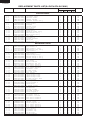
REPLACEMENT PARTS LIST(SJ-P47N/47N-SL1/WH1)
REF. NO.
PART NO.
DESCRIPTION
Q'TY
CODE
SJ-P47N SJ-P47N SJ-47N
-SL1
-WH1
-SL1
SJ-47N
-WH1
ELECTRIC PARTS
11111111111111111111-
1
2
3
4
5
6
7
8
9
10
11
17
20
21
22
33
45
46
50
55
RTHM-A103CBZZ
RSTT-A134CBE0
QSWTDA047CBZZ
PDMP-A050CBEZ
FTHM-A039CBKZ
RMOTRA046CBE0
QSOCAA084CBEZ
RLMP-A029CBEZ
QACC-A156CBZZ
QSW-PA090CBZA
RHOG-A161CBZZ
FFS-TA061CBKZ
FW-VZA146CBEZ
FHETBA161CBEZ
FCNW-A733CBKZ
QCNW-A886CBE0
FTRN-A014CBKZ
QCNW-B104CBZZ
FPWB-A337CBKZ
FPWB-A336CBKZ
F-themostat
Starting relay
Defrost timer
Damper thermo
Defrost thermo.ass’y
Fan motor
Lamp socket
Lamp15w
Source cord
Door switch
Protector
Fuse ass’y
Lead ev-cover ass’y
Def.heater ass’y
Relay wire ass’y
Olr cord
Ionaizer-k
Plasma harness
Main pwb
Panel pwb ass’y
222222222222222222222222222222222222222222222222222-
2
4
7
7- 1
7- 2
8
8- 2
13
14
15
16
17
19
20
21
22
23
24
26
27
28
29
29
29
31
38
38
39
43
44
45
46
47
49
50
55
56
57
63
64
65
66
67
68
69
70
71
72
73
77
78
JKNB-A036CBFC
LANG-A059CBPZ
FLEGPA083CBKZ
FAJS-A015CBKZ
LHLD-A533CBPZ
FLEGPA084CBKZ
LHLD-A534CBPZ
DHNG-A437CBMZ
DHNG-A419CBMZ
DHNG-A418CBMZ
GCOV-A210CBFZ
LCRA-A022CBPZ
LHLD-A389CBF0
NFANPA011CBF0
PSEL-C067CBEZ
PSEL-C068CBEZ
PSEL-C066CBEZ
PCOVPA308CBFA
PCOV-A277CBFA
GCOVPA142CBRA
HGRL-A206CBRA
GCOV-A228CBFA
GCOV-A228CBFF
GCOV-A228CBFH
JKNB-A033CBFC
PGID-A161CBFZ
PGID-A168CBFZ
PGID-A162CBFZ
LPLTPA323CBMA
HGRL-A237CBFA
HGRL-A238CBFA
PFIL-A050CBEZ
LHLD-A672CBFZ
LSTPPA108CBFA
LSTPPA118CBFA
HGRL-A205CBFA
PFPFPB334CBFZ
PSEL-C085CBEZ
LHLD-A484CBFA
LHLD-A485CBFA
PSEL-B209CBE0
PSHEMA225CBPZ
LPLTMA633CBPZ
PSEL-A415CBE0
PSEL-C069CBEZ
PSEL-C135CBEZ
PSEL-A552CBE0
PSEL-C078CBEZ
PSEL-C079CBEZ
LHLD-A391CBE0
LPLTMA399CBP0
F-temp. control knob
Eva holder 47
Leg holder l ass’y
Adjustable leg ass’y
Leg holder l
Leg holder r ass’y
Leg holder r
Upper hinge ass’y
Bottom hinge r ass’y
Center hinge r ass’y
E.v cover
Fan clamp
Motor cushion
Propeller fan 100
E.v cover sealer a
E.v cover sealer b
E.v cover sealer c
Terminal cover
R lamp cover
R-c box cover
Fan louver
Upper hinge cover
Upper hinge cover
Upper hinge cover
R-temp.control knob
R-air guider
R-air guider
R-air guider s
Panel base
F deodo.louver
R deodo.louver
Deodorizer
Plasma holder
Chilled stopper
Case stopper v
Multi louver l
R-louver insu.l
A-sealer r-louver
Fan motor holder b
Fan motor holder a
U-sealer handle
Heater cover
Drain support al
E.v cover sealer c
E.v cover sealer d
E.v cover sealer e
Dial sealer
A-sealer ag1
A-sealer ag2
Sl-5n clip
Dryer support
1
1
1
1
1
1
1
1
1
1
1
1
1
1
1
1
1
1
1
1
1
1
1
1
1
1
1
1
1
1
1
1
1
1
1
1
1
1
1
1
1
1
1
1
1
1
1
1
1
1
1
1
1
1
1
1
-
1
1
1
1
1
1
1
1
1
1
1
1
1
1
1
1
-
AV
AS
AZ
AW
AM
AZ
AL
AH
AQ
AS
AX
AM
AL
AY
AP
AE
AZ
AF
BC
AT
1
2
1
2
1
1
1
1
1
1
1
1
2
1
1
1
1
1
1
1
1
1
1
1
1
1
1
2
1
2
2
1
1
2
1
1
2
1
1
1
1
1
1
2
1
1
1
1
2
1
2
1
1
1
1
1
1
1
1
2
1
1
1
1
1
1
1
1
1
1
1
1
1
1
2
1
2
2
1
1
2
1
1
2
1
1
1
1
1
1
2
1
1
1
1
2
1
2
1
1
1
1
1
1
1
1
2
1
1
1
1
1
1
1
1
1
1
1
1
1
1
2
2
2
1
1
2
1
1
2
1
1
1
1
1
1
2
1
1
1
1
2
1
2
1
1
1
1
1
1
1
1
2
1
1
1
1
1
1
1
1
1
1
1
1
1
1
2
2
2
1
1
2
1
1
2
1
1
1
1
1
1
2
1
1
1
AC
AC
AF
AE
AL
AF
AP
AE
AD
AE
AR
AC
AF
AD
AA
AA
AC
AE
AE
AQ
AS
AE
AF
AE
AC
AG
AK
AC
AN
AE
AC
AM
AE
AC
AC
AM
AE
AC
AH
AH
AB
AC
AF
AC
AA
AC
AC
AC
AB
AD
AD
MECHANICAL PARTS
30
SJ-P43N/43N
SJ-P47N/47N
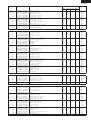
REF. NO.
PART NO.
DESCRIPTION
Q'TY
CODE
SJ-P47N SJ-P47N SJ-47N
-SL1
-WH1
-SL1
2222222222222-
79
80
81
82
83
87
91
93
94
95
99
100
101
LBND-A019CBE0
PBOX-A132CBFA
PBOX-A143CBFA
PCOVPA373CBFA
PSEL-C080CBEZ
LBND-A018CBE0
HGRL-A202CBFA
PCAP-A068CBFA
PSEL-C137CBEZ
PSHEMA231CBEZ
PSEL-A562CBE0
PSEL-C138CBEZ
PSEL-C139CBEZ
Nylon band
Terminal box
Terminal box-b
Terminal cover-b
A-sealer ag3
Fastening band a
F return cover
C sliding cap a
E.v cover sealer f
Ev cover al a
Leading wire sealer
E.v cover sealer g
Ev-insulation 47
SJ-47N
-WH1
1
1
1
1
1
1
1
4
1
1
1
1
2
1
1
1
1
1
1
1
4
1
1
1
1
2
1
1
1
1
1
4
1
1
1
1
2
1
1
1
1
1
4
1
1
1
1
2
AB
AF
AH
AN
AA
AP
AF
AC
AB
AC
AC
AA
AC
1
1
1
1
2
1
1
1
1
1
1
1
1
1
1
1
1
1
1
1
1
1
1
1
2
1
1
1
1
1
1
1
1
1
1
1
1
1
1
1
1
1
1
1
1
1
1
2
1
1
1
1
1
1
1
1
1
1
1
1
1
-
1
1
1
1
1
1
2
1
1
1
1
1
1
1
1
1
1
1
1
1
-
BS
BS
BS
BU
AD
AC
AD
AK
AN
AN
AT
AH
AN
AD
AH
AM
BW
BU
BU
BS
AD
AC
AF
AV
AN
AP
AD
AK
BA
AH
4
8
8
1
4
4
8
8
1
4
4
8
2
1
1
4
4
8
2
1
1
4
AC
AC
AH
AH
AC
AB
1
2
3
1
1
1
1
1
1
1
1
1
1
1
2
2
2
1
1
1
1
2
3
1
1
1
1
1
1
1
1
1
1
1
2
2
2
1
1
1
1
2
3
1
1
1
1
1
1
1
1
1
1
1
2
2
2
1
1
1
1
2
3
1
1
1
1
1
1
1
1
1
1
1
2
2
2
1
1
1
AR
AH
AM
AL
AH
AS
AT
AN
AN
AM
AG
AX
AL
AV
AN
AR
AU
AS
AR
AW
AS
DOOR PARTS
333333333333333333333333333333-
5
5
5
5
5- 1
5- 2
5- 3
5- 4
5- 5
5- 5
6
7
8
9
10
11
15
15
15
15
15- 1
15- 2
15- 3
17
19
20
21
22
30
31
FDORFB832CBKZ
FDORFB833CBKZ
FDORFB847CBKZ
FDORFB848CBKZ
LSTPPA131CBFA
NBRGPA033CBFA
LSTPMA008CBM0
GDAI-A071CBMZ
HBDGDA946CBEA
HBDGDA946CBEC
FPACGA346CBKZ
HDECQA475CBMA
HDECQA476CBRA
LPLTMA686CBPZ
LPLTPA374CBFA
HDECQA478CBMA
FDORRB639CBKZ
FDORRB641CBKZ
FDORRB659CBKZ
FDORRB660CBKZ
LSTPPA084CBFA
NBRGPA022CBFA
LSTP-A058CBM0
FPACGA347CBKZ
HDECQA477CBRA
HDECQA479CBMA
LPLTMA687CBPZ
LPLTPA375CBFA
GCOVPA177CBRA
HBDG-A005CBEA
F-door ass’y
F-door ass’y
F-door ass’y
F-door ass’y
Fd-stopper spring r
Nylon bearing 3f
F-door stopper r
Badge base
Badge
Badge
F-door packing
Hd cap
Handle trim f
Hd support f
Handle base f
Hd cover ft
R-door ass’y
R-door ass’y
R-door ass’y
R-door ass’y
Rd-stopper spring r
Nylon bearing 3s
R-door stopper r
R-door packing
Handle trim r
Hd cover rb
Hd support r
Handle base r
Panel cover
Pc badge
OTHER PARTS
444444-
1
3
11
12
15
17
LBND-A023CBE0
LX-VZA022CBZZ
QTAN-A012CBE0
QTAN-A013CBE0
LX-BZA090CBZZ
LX-WZA035CBZZ
L-band c
Special screw
Solderless term. b
Solderless term. a
Special screw
Washer
555555555555555555555-
1
2
3
4
5
6
9
13
13
14
15
16
17
18
19
24
242425
2525-
UPOK-A180CBRA
UPOKPA268CBFA
UPOK-A179CBRA
UPOK-A181CBRA
UTNA-A282CBFA
FSRA-A193CBYZ
USRA-A270CBFA
HGRL-A239CBFA
HGRL-A239CBFC
USRA-A268CBFA
GGAD-A032CBFA
UYOK-A401CBFA
UYOK-A399CBFA
UYOK-A400CBFA
GDORPA072CBRA
FTNA-A394CBKZ
UTNA-A377CBEZ
UWAKPA014CBFA
FTNA-A395CBKZ
UTNA-A378CBEZ
UWAKPA015CBFA
Bottle pocket
R door pocket s
Door pocket
R door pocket
Egg tray
Ice cube maker
Freezer tray
Ventilating grille
Ventilating grille
Evaporating pan
V parting plate
Vegetable case
Ice storage box
Fresh case
Fresh door hs
R glass shelf ass’y
Glass shelf r
G guard r
V glass shelf ass’y
Glass shelf v
G guard v
ATTACHMENT PARTS
1
2
1
2
31
SJ-P43N/43N
SJ-P47N/47N
REF. NO.
PART NO.
DESCRIPTION
Q'TY
CODE
SJ-P47N SJ-P47N SJ-47N
-SL1
-WH1
-SL1
5- 31
5- 32
5- 35
LRALPA136CBFA
LRALPA137CBFA
UPOKPA269CBFA
Ice tray holder l
Ice tray holder r
Bottle stopper
666666666666666-
PCMPLA215CBEZ
PSPAGA042CBE0
FFRM-A120CBKZ
FDRY-A006CBK0
PCLI-A050CBE0
PSPAFA034CBE0
PPIPCA386CBEZ
PPIPCA252CBE0
FPIPCA172CBKZ
PCOVPA246CBE0
PGUM-A004CBF0
QTAN-A045CBE0
FPIPCA162CBKZ
LANG-A058CBPZ
PGUM-A003CBF0
Compressor
Rubber grommet
Base frame ass’y
Dryer ass’y
Clip
Sleeve
S.p connector
Charge pipe
Discharge p. ass’y
Terminal cover
Absorbent rubber a
Terminal block
Eva pan pipe s ass’y
Absorbent rubber clm
Absorbent rubber b
TINS-A684CBRZ
TLAB-A876CBRZ
SPAKCA166CBZZ
CPADBA799YDKZ
CPADBA057CBKZ
SPADBA190CBFZ
SPADBA191CBFZ
SPADBC435YDEZ
SPADBC436YDEZ
TLAB-B273CBRZ
TLAB-A637CBR0
TLAB-A638CBR0
TLAB-A639CBR0
TLAB-A640CBR0
TLAB-A641CBR0
TLAB-A642CBR0
TLAB-A643CBR0
TLAB-A644CBR0
TLAB-B055CBEZ
TLAB-A985CBRZ
TLAB-A939CBRZ
TINS-A682CBRZ
Operation manual
Warning label
Packing case 47n
Bottom pad ass’y
Top pad ass’y
Corner post fl
Corner post fr
Corner post bl
Corner post br
Energy label
Energy label (GB)
Energy label (D)
Energy label (F)
Energy label (E)
Energy label (I)
Energy label (GR)
Energy label (P)
Energy label (NL)
R-door pocket label
Two star label
Caution label rof
Caution sheet weee
SJ-47N
-WH1
1
1
1
1
1
1
1
1
1
1
1
1
AG
AG
AC
1
4
1
1
1
4
1
2
1
1
2
1
1
2
2
1
4
1
1
1
4
1
2
1
1
2
1
1
2
2
1
4
1
1
1
4
1
2
1
1
2
1
1
2
2
1
4
1
1
1
4
1
2
1
1
2
1
1
2
2
BW
AE
AG
AX
AD
AD
AF
AD
AM
AL
AH
AQ
AS
AC
AH
1
1
1
1
1
1
1
1
1
1
1
1
1
1
1
1
1
1
1
1
1
1
1
1
1
1
1
1
1
1
1
1
1
1
1
1
1
1
1
1
1
1
1
1
1
1
1
1
1
1
1
1
1
1
1
1
1
1
1
1
1
1
1
1
1
1
1
1
1
1
1
1
1
1
1
1
1
1
1
1
1
1
1
1
1
1
1
1
AF
AC
BA
AV
AR
AK
AL
AG
AG
AE
AG
AG
AG
AG
AG
AG
AG
AG
AC
AF
AD
AC
CYCLE PARTS
1
2
4
5
6
9
11
18
19
21
24
25
26
28
29
MISCELLANEOUS
90909090909090909090909090909090909090909090-
1
2
3
6
7
8
9
10
11
12
13
13
13
13
13
13
13
13
15
19
21
34
HOW TO ORDER REPLACEMENT PARTS
To have your order filled promptly and correctly, please furnish the following information.
1. MODEL NUMBER
3. PART NO.
2. REF. NO.
4. DESCRIPTION
32
SJ-P43N/43N
SJ-P47N/47N
1
2
3
4
5
6
DOOR PARTS
A
SJ-P43N,P47N
A
SJ-43N,47N
3-6
3-6
3-5
3-5
3-5-2
3-10
3-11
B
B
3-9
3-8
1-55
3-31
C
2-43
3-5-4
3-30
C
3-5-5
3-7
3-5-3
3-5-3
3-5-1
3-5-1
3-15
D
D
3-15-2
3-7
3-19
3-21
5-3
5-5
E
E
5-4
3-22
90-15
3-20
5-2
F
F
5-2
5-35
3-17
G
G
3-15-3
5-1
3-15-1
5-3
SJ-P43N
SJ-43N
SJ-P47N
SJ-47N
H
1
2
3
4
33
5
6
H
SJ-P43N/43N
SJ-P47N/47N
1
2
3
4
5
6
CABINET PARTS
A
A
5-9
5-31
B
B
5-6
5-17
5-32
2-93
5-18
C
C
2-29
2-13
2-93
5-19
D
D
5-24
2-91
5-24-1
5-24-2
2-49
1-10
E
E
2-49
4-3 2-15
5-25
5-25-1
5-25-2
F
F
5-15
2-14
5-13
2-93
2-8
G
G
5-16
2-7
2-93
2-7-2
2-7-1
2-8-2
2-7-1
SJ-P43N
SJ-43N
SJ-P47N
SJ-47N
H
1
2
3
4
34
5
6
H
SJ-P43N/43N
SJ-P47N/47N
1
2
3
4
5
6
CABINET PARTS
A
A
2-19
1-6
2-63
2-64 2-19
2-23
2-17
1-5
2-16
4-1
2-100
2-65
2-20
1-20
4-1
B
B
2-94
2-68
2-21
2-28
2-95
2-22
2-101
1-1
1-9
1-17
2-4
2-70
C
2-44
C
2-69
2-46
4-11 (4-12)
2-2
2-66
1-21
2-72
1-4
2-24
2-79
1-3
2-67
2-99
2-39 (Only for SJ-43N,47N)
2-47
D
2-38
2-78
2-83
6-18
2-73
6-5
1-45
2-71
2-77
2-80
1-50
2-81
1-46
2-82
(Only for SJ-P43N,P47N)
2-46
D
(Only for SJ-P43N,P47N)
2-45
2-27
1-22
E
E
2-87
2-50
6-28
6-24
1-7
2-31
1-8
6-26
6-29
90-2
5-14
F
F
2-57
6-11
6-1
2-56
2-26
4-17
6-18
6-19
2-55
1-33
1-11
6-9
6-2
6-25
4-15
6-21
6-6
G
G
1-2
6-4
SJ-P43N
SJ-43N
SJ-P47N
SJ-47N
H
1
2
3
4
35
5
6
H
SJ-P43N/43N
SJ-P47N/47N
COPYRIGHT © 2005 BY SHARP CORPORATION
ALL RIGHTS RESERVED.
No part of this publication may be reproduced, stored in retrieval systems, or
transmitted in any form or by any means,
electronic, mechanical, photocopying, recording, or otherwise, without prior written permission of the publisher.
43ATUE/ 43ATTE/ 43BTUE/ 43BTTE/ 47ATUE/ 47ATTE/ 47BTUE/ 47BTTE
36
2005 SHARP CORP. (01K0.01E) Printed in Japan