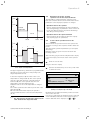
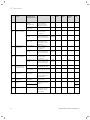
1
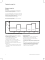
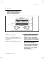
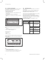
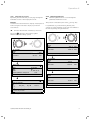
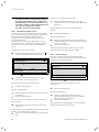
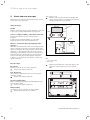
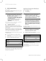
For the operator / for the expert technician
Operating and Installation Manual
VRT 392f
Room thermostat with radio transmission
GB
VRT 392f
For the owner
Operating manual
VRT 392f
Room thermostat
VRT 392f
Contents
Equipment properties ................................................4
Application ............................................................................4
Product specifications ........................................................4
1
1.1
1.2
1.3
1.4
Notes on the documentation ......................... 5
Storage of the documents ....................................5
Symbols used ...........................................................5
Validity of the instructions ...................................5
CE label ......................................................................5
2
Safety ............................................................... 5
3
3.1
3.2
3.3
3.4
3.5
Instructions for operation ............................. 6
Intended use .............................................................6
Ambient conditions .................................................6
Care ............................................................................6
Manufacturer's guarantee.....................................6
Recycling and disposal ...........................................6
4
4.1
4.2
4.3
4.3.1
Operation ......................................................... 7
Overview operating and display front................7
Overview of the displays .......................................8
Operating concept ..................................................8
Show various screens ............................................9
4.3.2
4.3.3
4.4
4.5
4.6
4.7
4.7.1
4.7.2
4.7.3
4.7.4
4.7.5
5
Changing parameters .............................................9
Operation in the default display ..........................11
Changing the target room temperature ...........12
Operation level for the operator, operation
level for the expert technician ............................13
Screens at the operation level for the
operator ....................................................................13
Editing screens (examples) ................................. 15
Entering time programmes
(example for heating) ........................................... 15
Programming holiday periods ............................ 16
Heating settings .................................................... 16
Entering the parameters for hot water
generation ................................................................17
Changing the name of the system
components .............................................................17
Status and error messages ......................... 18
Equipment properties
Equipment properties
Application
The VRT 392f is a programmable room temperature
controller for the heating system. The VRT 392f also
controls the hot water generation.
You can use the VRT 392f to specify various room target
temperatures (programming) — for different times of the
day and for different days of the week.
In automatic mode, the VRT 392f controls your heating
in accordance with this input (see Fig. 0.1).
Room temperature
You can also use the VRT 392f to define daily heat-up
times for hot water generation.
25 °
20 °
Set back temperature
15 °
Period 1
04:00
Fig. 0.1
08:00
12:00
16:00
Period 3
20:00
Time
Automatic heating operation: Example of setting the
room target temperature for different times of the day
In addition, the VRT 392f can be used to control the
following accessory components:
– Circulation pump for water heating in combination
with a VR 40 multi-functional module
– Conventional hot water cylinder
– Vaillant layer type storage tank actoSTOR
The VRT 392f can be part of a new heating and hot
water system or it can be incorporated into
existing heating systems. The appliance must have an
eBUS interface.
eBUS is a standard communication method used for
the exchange of data between heating technology
components.
4
Period 2
Product specifications
– eBUS interface
– Wireless communication with a Vaillant appliance
– Illuminated graphical display (display field)
– Operation via both dials in accordance with the
principle "Turn and Click"
– The radio receiver unit can be mounted directly on the
operating panel of the appliance or separately on the
wall
- The controller can be mounted separately on the wall
– Equipped for operation with the Vaillant diagnosis
software vrDIALOG 810/2 and the Vaillant Internet
Communication System vrnetDIALOG, i.e. remote
diagnosis and remote adjustment
Operating manual VRT 392f 0020044239_00
Notes on the documentation 1
Safety 2
1
Notes on the documentation
The following notes are intended to help you throughout
the entire documentation. Further documents
apply in combination with this operating manual.
We accept no liability for any damage caused by failure
to observe these instructions.
Other applicable documents
– Installation instructions for the Vaillant room
thermostat VRT 392f (Part 2 of this document;
for the expert technician)
– The operating and installation instructions for your
heating system
– All instructions for the accessories
Glossary
An explanation of technical terms and important
functions is provided in alphabetical order at the end of
this document.
1.3
Validity of the instructions
These operating instructions apply exclusively for
equipment with the following part numbers:
0020028510, 0020028511, 0020028512, 0020028513,
0020028514
4024074518083, 4024074518090, 4024074518106,
4024074518113, 4024074518328
The part number of your equipment can be obtained
from your expert technician.
1.4
CE label
The CE label confirms that the Vaillant Room
Temperature Controller VRT 392f fulfils the
fundamental requirements of the following relevant
directives.
2
1.1
Storage of the documents
Please store this operating manual and all related
documents in such a way that they are available
whenever required.
1.2
Symbols used
Please observe the safety instructions in this manual for
the installation of the appliance!
e Danger!
Immediate risk of serious injury or death!
e Danger!
Danger of death by electric shock!
Caution!
H Danger
of burning and scalding!
Caution!
a Potentially
dangerous situation for the product
and environment!
h Note
Useful information and tips.
Symbol for a necessary task
Operating manual VRT 392f 0020044239_00
Safety
The VRT 392f may only be installed by a certified expert
technician. This person is also responsible for the proper
installation and initial operation.
H Caution!
Risk of being scalded by hot water!
When the target temperature is
above 60 °C, there is a risk of scalding at the
hot water taps. Small children and elderly
people can be at danger even at lower
temperatures.
Risk to persons should be excluded through the
selection of an appropriate target temperature
(see Section 4.7.4).
Caution!
Risk of being scalded by hot water!
If your expert technician has activated the
anti-legionella function for the hot water
cylinder, the temperature of the hot water at
the draw-off points may exceed 60 °C at
specific times.
Find out from your expert technician whether
the anti-legionella function has been activated
and if so, on what day and at what time.
5
3 Instructions for operation
3
Instructions for operation
3.1
Intended use
The VRT 392f is a state-of-the-art device which has
been constructed in accordance with the standard safety
regulations.
However, in the event of improper use or use not as
intended, impairment of the equipment and other items
can arise.
The VRT 392f serves the room temperature and timedependent control of a heating installation with or
without hot water generation/circulation pump in
conjunction with a Vaillant appliance and an eBUS
interface.
Operation with the following accessories is permissible:
– Circulation pump for water heating in combination
with a VR 40 multi-functional module
– Conventional hot water cylinder
– Vaillant layer type storage tank actoSTOR
Any other use or extended use is considered to be use
other than intended. The manufacturer or supplier is not
liable for any resulting damage. The owner alone bears
any risk.
Intended use also includes observance of the Operating
and Installation Manual as well as all other applicable
documents.
3.2
Ambient conditions
The controller and radio receiver unit may only be
installed in dry rooms.
Please make sure:
– that the air in the room can circulate freely around the
VRT 392f and the VRT 392f is not covered by
furniture, curtains or other objects.
– that all the radiators in the room where the VRT 392f
is fitted are fully on.
3.4
Manufacturer's guarantee
Vaillant warranty
We only grant a Vaillant manufacturers warranty if
a suitably qualified engineer has installed the system in
accordance with Vaillant instructions. The system owner
will be granted a warranty in accordance with the
Vaillant terms and conditions. All requests for work
during the guarantee period must be made to
Vaillant Service Solutions (0870 6060 777).
Vaillant Service
To ensure regular servicing, it is strongly recommended
that arrangements are made for a Maintenance
Agreement. Please contact Vaillant Service Solutions
(0870 6060 777) for further details.
3.5
Recycling and disposal
Your VRT 392f and its packaging are primarily made
of recyclable raw materials.
Appliance
The VRT 392f and its accessories must not be disposed
of in the household waste. Make sure the old device and
any existing accessories are disposed of properly.
Packaging
Please leave the disposal of the transport packaging to
the qualified servicing company which installed the
appliance.
Batteries
Batteries must not be disposed of in the household
waste. Ensure that the batteries are disposed of
properly.
3.3
Care
Clean the casing of the VRT 392f with a damp cloth.
Do not use abrasive materials or cleaning agents that
could damage the operator control elements, parts of
the casing or display.
6
Operating manual VRT 392f 0020044239_00
Operation 4
4
Operation
h Note
Have your expert technician explain the
operator input for the controller once the
installation is complete. This will prevent the
settings being changed unintentionally.
4.1
Overview operating and display front
1
Th. 12.01.06
11:46
19.0 °C
Auto
VRT 392f
3
Fig. 4.1
2
Overview of operator control and display panel
Key
1 Display
2 Operating element of the right-hand dial
3 Operating element of the left-hand dial
Fig. 4.1 shows the default display. The following
information can be obtained from the default display:
– the type of operation (automatic, manual or off) of the
heating circuit
– the current room temperature
The default display is described in detail in Section 4.3.3.
The functions of both dials are described in Section 4.3.
Operating manual VRT 392f 0020044239_00
h Note
The display is normally switched off to save
power. This increases the service life of the
batteries.
The display and lighting are activated as soon
as you turn or click one of the dials. If the
appliance is not used for more than one minute
the basic display returns and switches off after
approx. 10 minutes.
Note
When the dial is turned the values to be
displayed must first be called up by the radio
receiver unit. Until these values are obtained
only dashes instead of values will be displayed
(--). This generally takes up to two seconds.
Depending on the ambient conditions, it may
take up to 15 minutes until the current data are
called up by the radio receiver unit and are
subsequently displayed.
If dashes (--) are displayed continuously,
consult your expert technician.
7
4 Operation
4.2
Overview of the displays
The display and input parameters (operating values) of
the VRT 392f are shown on the various screens.
The screens are sub-divided into:
– Default display (Fig. 4.8)
– Basic display (Fig. 4.2)
– Display/input screens for certain parameters in the
operator level
– Display/input screens for operating and
system-specific parameters at the expert technician
level
All the screens are divided into three areas.
Th. 12.01.06
11:46
1
HC1
21.0 °C
Auto
Hot water
56.0 °C
Auto
4.3
Operating concept
The operator input in the default display is described in
Section 4.3.3.
The operating concept described below applies to the
basic display (Fig. 4.2) and to the various different
display/input screens of the user level.
The two dials (Fig. 4.1 Items 2 and 3) function according
to the Vaillant "Turn and Click" principle.
When turning (forwards or backwards) the adjusters
locate in the next position with a detectable click. Each
index step also moves the cursor one position forwards
or backwards in the display.
By clicking (pressing) you can highlight or accept
changes to a parameter.
2
Left-hand dial
> Change room temperature
3
Right-hand dial
Action
Result
Turn
Scroll to next screen
Turn
Scroll to an
input field within
a screen (marked by
cursor )
Fig. 4.2 Overview display (example basic display)
Key
1 Area for basic data, title of the screen or status and error
messages
2 Area for display and input of parameters
3 Area for display of explanations
The basic data are:
– Current day
– Date
– Time of the day
Changing a parameter
Clicking
(pushing)
Highlight for
changing
Turn
Change the
parameter value
Clicking
(pushing)
Acceptance of
selected parameter
value
Table 4.1 Operating concept
The title of the screen appears instead of the basic data
in the display/input screens for the specific parameters
(see Fig. 4.12).
Th. 12.01.06
11:46
HC1
21.0 °C
Auto
Hot water
56.0 °C
Auto
> Change room temperature
1
2
3
4
Fig. 4.3 Area for display and input of parameters
(example basic display)
Key
1 Parameter name (only display)
2 The cursor marks the jump to a modifiable value
3 Input field for parameter values; here: target set temperature
4 Input field for parameter values; here: Operating mode
8
Operating manual VRT 392f 0020044239_00
Operation 4
4.3.1 Show various screens
By turning the left-hand dial you can page through the
individual screens of the display like a book.
4.3.2
Changing parameters
Turn the right-hand dial to scroll through the
parameters within the screen.
Example:
You are now located in the basic display. A description of
how to navigate to the basic display is provided in
Section 4.3.3.
The position is indicated by the cursor (see Fig. 4.5).
If a parameter (e.g. a date with day, month, year)
consists of several elements, scroll from one element to
the next by turning the right-hand dial.
Turn the left-hand dial clockwise by one notch.
The screen 1 appears in the display together
with the basic data setting options.
Th. 12.01.06
11:46
HC1
22.0 °C
Auto
Hot water
56.0 °C
Auto
> Change room temperature
Basic data
1
Date
Day
Time
Summer/Winter changeover
21. 06. 06
We
12 : 00 o'clock
Auto
21.0 °C
Auto
Hot water
56.0 °C
Auto
Th. 12.01.06
11:46
HC1
21.0 °C
Auto
Hot water
56.0 °C
Auto
> Change room temperature
> Change operating mode
> Select day
HC 1
Time programme
Mo
1
06 : 00 2
:
3
:
-
Th. 12.01.06
11:46
HC1
2
Th. 12.01.06
11:46
HC1
21.0 °C
Auto
Hot water
56.0 °C
Auto
> Change target hot water
10 : 40
:
:
21.5 °C
Fig. 4.5 Scroll to various different modifiable parameters
> Select day of week
Fig. 4.4 Display of the various screens
Operating manual VRT 392f 0020044239_00
9
4 Operation
Click the right-hand dial.
Turn the right-hand dial to show the
possible values.
The parameter value marked by the cursor is inversely
displayed.
Th. 12.01.06
11:46
HC1
21.0 °C
Auto
Hot water
56.0 °C
Auto
Th. 12.01.06
11:46
HC1
21.0 °C
Auto
Hot water
56.0 °C
Auto
Th. 12.01.06
11:46
HC1
21.5 °C
Auto
Hot water
56.0 °C
Auto
Th. 12.01.06
11:46
HC1
22.0 °C
Auto
Hot water
56.0 °C
Auto
> Change room temperature
> Change room temperature
Fig. 4.6
Highlighting a parameter
> Change room temperature
> Change room temperature
Fig. 4.7 Changing the values of a parameter
Click the right-hand dial.
The value displayed is confirmed and adopted for control
purposes. The value is saved and is no longer
highlighted.
10
Operating manual VRT 392f 0020044239_00
Operation 4
Hot water
Heating circuit (HC1)
Changing parameters in the basic display
Parameter
Meaning
Room target
temperature
The heating is controlled with
reference to the modified room target
temperature for a specific period that
depends on the operating mode
selected, also see Section 4.4.
Operating
mode
Auto(matic)
The control of the heating unit is
carried out in accordance with the
preset room set target temperature,
the time programmes and other
parameters such as e.g. night set back
temp.
Some of these parameters are set by
your expert technician.
Operating
mode
Manual
The control of the heating unit
depends upon the set room target
temperature.
Operating
mode
OFF
The appliance is switched off. The
room temperature is not displayed and
cannot be changed.
Frost protection (room set target
temperature = 5 °C) is guaranteed.
Hot water
target set
temperature
The water heating is controlled with
reference to the modified target hot
water value for a specific period that
depends on the operating mode
selected, also see Section 4.4.
Operating
mode
Auto(matic)
The hot water generation is controlled
according to the target hot water and
time programme settings.
Operating
mode
Manual
The hot water generation is controlled
with reference to the target hot water
setting.
Operating
mode
OFF
The hot water is switched off. The
target hot water temperature is not
displayed and cannot be changed.
Frost protection is active.
Table 4.2 Modifiable parameters in the basic display
Example: Change the room set target temperature of
the heating circuit (HC1)
Initial condition: You are in the basic display
(see Fig. 4.2). A description of how to navigate to the
basic display is provided in Section 4.3.3.
The new value is applied. The display changes from
inverse back to normal.
This new value applies to the control for a specific
period, depending on the operating mode selected;
also see Section 4.4.
4.3.3 Operation in the default display
In the simplified basic display (Fig. 4.8) in the central
area the operating mode for the heating circuit and the
internal temperature are displayed.
The default display also provides you with the option of
changing the two most important parameters of your
heating system quickly and comfortably:
- By turning the left-hand dial you change the operating
mode (automatic, manual, off).
- By turning the right-hand dial you can change between
the actual room temperature and the set room
temperature.
Th. 12.01.06
11:46
Auto
VRT 392f
Fig. 4.8 Default display (example)
You can navigate from the default display to the
next screen by clicking one or both dials (see Fig. 4.2).
If the controller is not operated for more than one
minute, the display changes to the default display.
Changing the operating mode in the default display
Operating
mode
Meaning
Auto(matic)
The heating circuit is controlled with reference
to the specified room target temperature, the
time programme and other parameters, e.g.
night set back temp.
Some of these parameters are set by your
expert technician.
Manual
The control of the appliance depends upon the
set room temperature.
OFF
The heating circuit is switched off. The room
temperature is not displayed and cannot be
changed.
Frost protection (room set target
temperature = 5 °C) is guaranteed.
Turn the dial on the right until the cursor
appears in front of the target value (room target
temperature) of the heating circuit (HC1).
Click the right-hand dial.
The input field for the target value is inversely displayed.
Turn the right-hand dial.
The value for the room temperature changes by 0.5 °C
for each index turn of the dial.
19.0 °C
Table 4.3 Operating modes of the heating circuit
Click the right-hand dial once the
required value for the room target temperature
has been reached.
Operating manual VRT 392f 0020044239_00
11
4 Operation
This is how to do it:
Turn the left-hand dial.
The operating mode is highlighted.
After a delay of one second, you can select the
operating mode.
Continue to turn the left-hand dial until the
desired operating mode is displayed.
The selected operating mode is accepted after a delay of
two seconds. The display changes from inverse back to
normal.
Th. 12.01.06
11:46
20.5 °C
Auto
> change room temperature
Fig. 4.10 Changing the room temperature in the basic display
This new value applies to the control for a specific
period, depending on the operating mode selected; also
see Section 4.4.
Th. 12.01.06
11:46
Manual
19.0 °C
> Change operating mode
4.4
Changing the target room temperature
If you change a target value - either the room target
temperature or the target hot water - in the basic
display or in the default display, the new value overrides
the programmed temperatures.
When in „Manual“ mode, the control uses the temporary
temperatures until either the operation mode or the
temperature is changed.
Fig. 4.9 Changing the operating mode in the default display
Changing the room temperature in the default display
The control of the heating unit depends upon the set
room target temperature. The control system ensures
that the set room temperature is reached rapidly and is
retained at this level.
Turn the right-hand dial.
When in „automatic“ mode, the control uses the
temporary temperature until the next time window
starts (if you have changed the set target value outside
a time window) or until the end of the current time
window (if you have changed the set target value within
the time window); see Fig. 4.11.
Instead of the room temperature, the current set room
temperature is highlighted. After a delay of one second
you can select the new room target temperature:
Turn the right-hand dial further until the desired
room temperature appears.
The selected room target temperature is applied after
a delay of two seconds. The representation once again
changes from inverse to normal and shows the internal
temperature.
12
Operating manual VRT 392f 0020044239_00
Operation 4
Room temperature
4.5
Operation level for the operator,
operation level for the expert technician
The VRT 392f is equipped with two operation levels.
Each level contains several screens in which the various
parameters can be displayed, adjusted or changed.
25 °
20 °
– Operation level for the operator
Used to display and set/change the basic parameters.
The setting/changing of parameters can be carried out
by the user without any special previous knowledge
and during normal operation.
Set back
temperature
15 °
Period
08:00
– Operation level for the expert technician
Used exclusively by the expert technician to display
and set/change specific parameters.
12:00
Time
Room temperature
4.6
Screens at the operation level for the
operator
The screens at the operation level for the operator are
arranged according to the sequence shown in Table 4.4
below.
This table shows you which parameters you can adjust
and change.
Examples of this are given in Section 4.7 and in the
following sections.
25 °
2
3
1
20 °
4
15 °
This is the way you get from the simplified basic display
to the first display screen "basic data" of the operator
level:
Period
Click one or both dials.
08:00
12:00
Time
Fig. 4.11 Duration of validity of target value changes
(here: Target room temperature)
The upper diagram in Fig. 4.11 shows a programmed time
window (see Section 4.7.1) and corresponding room
target temperature (21 °C).
In the lower diagram, at (1) the value of the room
temperature is changed (20 °C). The control system
uses this value until the start of the time window.
From here (2) the control system uses the room
temperature of the time window (21 °C).
At (3) the value of the room temperature is changed
(17 °C).
The control system uses this value up to the end of the
time window (4).
Once the time window has elapsed, the system is
controlled with reference to the set-back temperature
(15 °C).
h Note
The characteristic described also applies to the
You get to the basic display.
Turn the left-hand dial by one or two points in the
clockwise direction.
Basic data
Date
Day
Time
Summer/Winter changeover
1
21. 06. 06
We
12 : 00 o'clock
Auto
> select day
Fig. 4.12 Screen "basic data"
(example: selecting the day of the week)
By turning the left-hand dial further you will scroll from
one screen to the next.
If accessory components are installed and are controlled
via the VRT 392f, additional screens apart from those
listed in Table 4.4 can be displayed, e.g. 3 or 6.
same extent for the target hot water.
Operating manual VRT 392f 0020044239_00
13
4 Operation
Screen
1
Title
screen
Adjustable
operating values
(only display = A)
Remarks
Basic data
Date
Weekday
Time of the day
Select Day, Month and
Year separately;
Select Hour and
Minutes separately
Unit
Min.
value
Max.
value
Summer/Winter
changeover
Default
value
Auto, Off
Off
Weekday/Block
Select a weekday or
a block of days
(e. g. Mo-Fr)
1 Start/End Time of
the day
2
3
There are three time
periods available per
day or block of days
Hours/
Minutes
Temperature each
time period
For each time period,
an individual room
temperature can be
determined
°C
Weekday/Block
Select a weekday or
a block of days
(e. g. Mo-Fr)
1 Start/End Time of
the day
2
3
There are three time
periods available per
day or block of days
Weekday/Block
Select a weekday or
a block of days
(e. g. Mo-Fr)
1 Start/End Time of
the day
2
3
There are three time
periods available per
day or block of days
Holiday
programming for
the total system
Holiday period
Start Day, Month, Year
End Day, Month, Year
Holiday set target
value heating
Room temperature for
the holiday time period
°C
5
30
0,5
10
8
HC1
parameters
Set-back
temperature
A set-back temperature
can be specified for the
periods between the
time windows.
°C
5
30
0,5
15
10
Hot water
parameters
Hot water target set
temperature
Target temperature for
water heating
°C
35
70
1,0
60
14
Changing the
name
Heating circuit 1
Any name having up to
8 characters can be
entered
Heating
circuit 1
Access to the level for
the installer only by
entering the saved
code number
1000
2
4
5
7
HC1
Time programme
Increment/
Selection
option
Hot water time
programme
Circulation pump
time programmes
Hot water
15
Release code level
Code number
10 min
5
30
0,5
Hours/
Minutes
10 min
Hours/
Minutes
10 min
20
Hot
water
Table 4.4 Screens at the operation level for the operator
14
Operating manual VRT 392f 0020044239_00
Operation 4
4.7
Editing screens (examples)
4.7.1
Entering time programmes (example for
heating)
Using the time programmes you can allocate up to three
time windows per weekday, or block of days
(e.g. Mo - Fr). In these time windows, the heating system
maintains the room temperature that you have selected,
the so-called comfort temperature. Outside the time
windows, the room temperature is set back. The
set-back temperature can also be changed.
h Note
You can save energy without any loss in heating
comfort by finding the best possible match
between the time windows and your lifestyle.
1, 2 and 3 indicate the "time windows" which you can
programme for the selected weekday or block of days.
The VRT 392f provides heating in accordance with the
corresponding comfort temperature (e.g. 21.5 °C) within
a specific time window (e.g. from 06:00 am to
10:40 am).
Turn the right-hand dial until the cursor is
positioned in front of the input field for the
starting time of time window 1.
Click the right-hand dial.
The field is highlighted.
Set the start time by turning the right-hand dial.
Each step of the dial changes the time by 10 minutes.
The example below for heating circuit 1 shows
example for the heating circuit. You can define time
windows in a similar way for hot water generation and
for a circulation pump.
Once the desired starting time is displayed,
confirm this by clicking the right-hand dial.
The end time for window 1 should be set similarly.
Turn the left-hand dial until screen
(HC1 time programme) is displayed.
HC 1
Time programme
Mo
1
06 : 00 2
:
3
:
-
2
The comfort temperature for time window 1 is set as
follows:
2
10 : 40
:
:
21.5 °C
> Select day of week
Fig. 4.13 Screen
2 (example)
Turn the right-hand dial until the cursor is
positioned in front of the day or block of days
input field.
Click the right-hand dial.
The field is highlighted.
–
–
–
–
Select the required day or block of days by turning
the right-hand dial. The following options are
available:
Mo, Tu, ... etc.
Mo - Fr (Block)
Sa - Su (Block)
Mo - Su (Block)
Confirm the selection by clicking with the
right-hand dial.
Operating manual VRT 392f 0020044239_00
Turn the right-hand dial until the cursor is
positioned in front of the input field for the
comfort temperature of time window 1.
Click the right-hand dial.
The field is highlighted.
Select the comfort temperature by turning the
right-hand dial (one step corresponds to a change
of 0.5 °C).
Once the desired comfort temperature is
displayed, confirm this by clicking
the right-hand dial.
h Note
The VRT 392f assists the operator with the
programming of time windows:
The times can only be entered in chronological
order. The time period of a subsequent window
cannot overlap the previous one.
The time window must be between 0:00 and
24:00.
An existing time window can be deleted as
follows: Se the start time and the end time of
a time window to the same time.
15
4 Operation
Enter the room temperature as follows:
h Note
The same procedure as shown in the example
for heating circuit applies when inputting the
time programme for hot water generation or for
a circulation pump. A comfort temperature does
not need to be entered for hot water
generation and the circulation pump.
4.7.2 Programming holiday periods
For a longer period of time when you are not at home,
you can define a lower room temperature. This will save
heating energy. The VRT 392f ensures that the
living spaces are only heated with reference to the
specified temperature.
You can specify a room target temperature of 15 °C
if you wish to go on holiday from 10 - 24 February. The
living rooms are only heated up to 15 °C during this
period.
Turn the left-hand dial until you reach screen
"Holiday programming for whole system".
Room value:
Click the right-hand dial.
The field is highlighted.
Turn the right-hand dial until the desired value is
displayed (values from 5 °C to 30 °C in half degree
steps are possible).
Click the right-hand dial.
7
7
.
The explanation text "Select room temperature"
appears.
The desired room set target temperature is set. The
display changes from inverse back to normal.
Holiday times can be set as follows:
Holiday programming
for whole system
Period
10. 02. 06 -
Turn the right-hand dial until the cursor is
positioned in front of the room target temperature
input field.
4.7.3 Heating settings
Here you can enter the set-back temperature. The
heating is controlled with reference to this temperature
outside the specified time window.
.
10 °C
HC1
Parameter
Night set back temperature
8
15 . 0 °C
> set start day
Fig. 4.14 Screen
7 (example)
Turn the right-hand dial until the cursor is
positioned in front of the start date.
The field shows the text "Set starting day".
> set temperatur
Fig. 4.15 Display screen
8 (example)
The display shows "Select temperature" as an
explanation.
Click the right-hand dial.
Click the right-hand dial.
The field is highlighted.
The field is highlighted.
Turn the right-hand dial until the desired start day
is displayed.
Click the right-hand dial.
The day date is set. The display changes from inverse
back to normal.
Set the month and year of the start date in the
same way.
Turn the right-hand dial until the desired
value is displayed (values from 5 °C to 30 °C in
half degree steps are possible).
Click the right-hand dial.
The required set-back temperature is set. The display
changes from inverse back to normal.
In the display field for explanation the text "Set starting
month“ or "Set starting year" appears.
Set the end date of the holiday period in the same
way.
16
Operating manual VRT 392f 0020044239_00
Operation 4
4.7.4
Entering the parameters for hot water
generation
If the hot water for your home is generated by the
appliance the target temperature can be entered
via the VRT 392f.
Click the right-hand dial.
The character is inversely displayed.
Turn the right-hand dial to select the correct letter
or number.
Click the right-hand dial.
Turn the left-hand dial until you reach Screen
"Hot water parameters".
10
The cursor is positioned in front of the value for the
target temperature.
Turn the right-hand dial by one indexing position
in the clockwise direction.
The next character is marked by the cursor.
Click the right-hand dial.
Click the right-hand dial.
The field is highlighted.
Turn the right-hand dial until the desired hot water
temperature is displayed (values from 35 °C to
70 ° C in one degree steps are possible).
Click the right-hand dial.
The required target temperature is set. The display
changes from inverse back to normal.
H
The required character is adopted. The character is
displayed normally once again.
Caution!
Risk of being scalded by hot water!
When the target temperature is
above 60 °C, there is a risk of scalding at the
hot water taps. Small children and elderly
people can be at danger even at lower
temperatures.
Select the target temperature so that nobody is
at danger.
The character is displayed inversely.
Turn the right-hand dial to select the correct letter
or number.
Continue in this way for the remaining characters
of the new name.
h Note
Entire names or superfluous characters can be
deleted by entering a blank.
4.7.5 Changing the name of the system components
On screen 14 you can see which names of
components you can change.
14
Changing the name
HC1
:
HC1
Hot water
:
:
Bath 1
> select
Fig. 4.16 Display screen
14 (example)
On the right-hand side of the colon you can enter a new
name (numbers 0-9, spaces, capital/small letters). This is
how to do it:
Turn the left-hand dial until you reach screen 14
"Change names".
Turn the right-hand dial until the cursor is
positioned in front of the character you wish to
change.
Operating manual VRT 392f 0020044239_00
17
5 Status and error messages
5
Status and error messages
Status and error messages are displayed in the second
row of the field for basic data.
This is how to do it:
Pull the controller (1) off the wall socket (2). This
can be done by pushing a screwdriver into the two
retaining straps (see Fig. 5.1 arrows).
Status messages
1
Holiday
Within a set holiday time period the heating is controlled
to the room set target temperature for this period.
Service + telephone number of the expert technician
Indicates maintenance for the heating system is
required.
In addition, the telephone number of your expert
technician appears if he has programmed it in.
Dashes (--) instead of values are displayed at the
controller
When the dial is turned the values to be displayed must
first be called up by the radio receiver unit. Until these
values are obtained only dashes instead of values will be
displayed (--). This generally takes up to two seconds.
Depending on the ambient conditions, it may take up to
15 minutes until the current data are called up by the
radio receiver unit and are subsequently displayed.
If dashes (--) are displayed continuously, consult your
expert technician.
2
Fig. 5.1
Removing the VRT 392f
Key
1 Controller VRT 392f
2 Wall socket
Error messages
Error boiler
Informs you about an error in the appliance.
Contact your expert technician.
Mount four new batteries of the same type for the
controller on the reverse side of the controller
PCB.
Com. Error boiler
The connection between the radio receiver unit and
appliance is faulty.
Contact your expert technician.
No radio communication
Radio communication between the VRT 392f and radio
receiver unit is faulty.
Contact your expert technician.
Change battery
The batteries at the controller are almost empty.
Change all batteries at the controller.
Fig. 5.2 Inserting the batteries
18
Operating manual VRT 392f 0020044239_00
Status and error messages 5
h Note
Ensure correct polarity of the batteries
(see Fig. 5.2).
Always change all batteries at the same time.
Only use the following battery type:
Alkaline AA/LR6 Battery 1.5 V.
Do not use rechargeable batteries.
Depending on use, the batteries last between
approx. 1 and 1.5 years.
Carefully push the controller onto the wall
socket (2) until it snaps into place.
The display remains dark
The display remains dark although you turn or click one
of the dials.
Change all batteries at the controller.
A description of how to do this is provided in this
Section under "Change battery")
h Note
The display is normally switched off to save
power. This increases the service life of the
batteries.
The display and lighting are activated as soon
as you turn or click one of the dials. If the
appliance is not used for more than one minute
the basic display returns and switches off after
approx. 10 minutes.
Status and fault messages of the radio receiver unit
green LED on:
red LED on:
everything OK
error (no communication with
appliance or controller)
red LED flashes briefly: radio transmission
green LED flashes:
the teach-in process was started
via a button (only relevant for
parts replacement)
Operating manual VRT 392f 0020044239_00
19
For the expert technician
Installation instructions
VRT 392f
Room thermostat
VRT 392f
Contents
1
1.1
1.2
1.3
Notes on the documentation .........................2
Storage of the documents ....................................2
Symbols used ...........................................................2
Validity of the instructions ...................................2
2
2.1
2.2
2.3
Description of the device ............................... 3
Identification plate ..................................................3
CE label ......................................................................3
Intended use .............................................................3
3
3.1
3.2
3.3
3.3.1
Safety instructions and regulations ............4
Safety instructions ..................................................4
Regulations ...............................................................4
General requirements ............................................4
Preliminary remarks for room sealed
appliances .................................................................4
3.3.2 Related documents .................................................4
4
4.1
4.2
4.3
4.4
4.4.1
4.5
Assembly ......................................................... 5
Scope of delivery.....................................................5
Accessories ...............................................................5
Installation location ................................................5
Installing the radio receiver unit in the
appliance ...................................................................5
Mounting the radio receiver unit on the wall ..6
Mounting the control on the wall ........................6
5
5.1
Installation ....................................................... 7
Electrical installation for the wall-mounted
wireless receiver unit .............................................7
6
6.1
6.2
6.3
Initial commissioning .....................................8
Installation assistant ..............................................8
Operation level for expert technician ................9
Resetting the parameters to the factory
setting ........................................................................9
Handover to the operator .....................................11
Faults ..........................................................................11
Special features .......................................................11
6.4
6.5
6.6
7
Factory customer service, manufacturer's
guarantee .........................................................11
8
Recycling and disposal ...................................11
9
Technical data ............................................... 12
Glossary .....................................................................13
1 Notes on the documentation
1
Notes on the documentation
The following notes are intended to help you throughout
the entire documentation. Further documents apply in
combination with this installation manual.
We accept no liability for any damage caused by failure
to observe these instructions.
Other applicable documents
– Operating manual for the Vaillant room thermostat
VRT 392f
– The operating and installation instructions for your
heating system
– All instructions for the accessories
1.3
Validity of the instructions
These installation instructions apply exclusively for
appliances with the following part numbers:
0020028510, 0020028511, 0020028512, 0020028513,
0020028514
The part number of your appliance can be taken from
the identification plate.
1.1
Storage of the documents
Please pass on this installation manual and all other
valid documents and auxiliary equipment to the owner
of the installation. He will then determine the method of
storage. The documents must be made available upon
request.
1.2
Symbols used
Please observe the safety instructions in this manual for
the installation of the appliance!
e Danger!
Immediate risk of serious injury or death!
e Danger!
Danger of death by electric shock!
H Attention!
Danger of burning and scalding!
Caution!
a Potentially
dangerous situation for the product
and environment!
h Note
Useful information and tips.
Symbol for a necessary task
2
Installation instructions VRT 392f 0020044239_00
Description of the device 2
2
Description of the device
The VRT 392f is a programmable room thermostat for
the heating and control of hot water generation in
conjunction with a Vaillant appliance (eBUS-compatible).
In addition, the VRT 392f can be used to control the
following accessory components:
– Circulation pump for water heating in combination
with a VR 40 multi-functional module
– Conventional hot water storage
– Vaillant layer type storage tank actoSTOR
With the VRT 392f power is supplied via 4 batteries
(Alkaline AA/LR6 1.5V).
With the VRT 392f data is exchanged via a radio link to
the radio receiver unit.
Power is supplied via an eBUS interface which also
facilitates the exchange of data between the radio
receiver unit and the appliance.
The VRT 392f is equipped for operation with the Vaillant
diagnosis software vrDIALOG 810/2 and the Vaillant
Internet Communication System vrnetDIALOG , i.e. for
remote diagnosis and adjustment.
1
2
2.1
Identification plate
The identification plate can be found on the back of the
controller electronics (PCB).
2.2
CE label
The CE label provides evidence that the Vaillant room
thermostat VRT 392f satisfies the basic requirements
contained in the following directives:
– Electromagnetic compatibility directive
(Guideline 89/336/EEC)
– Low voltage directive (Guideline 2006/95/EEC)
– Directive on Radio Equipment and Telecommunications
Terminal Equipment (R&TTE Directive 1995/5/EEC)
– Directive on Electromagnetic compatibility and Radio
spectrum Matters (ERM) (Directive ETSI EN 300220-2)
2.3
Intended use
The room thermostats VRT 392f are built using state-ofthe-art technology and according to the recognised
safety regulations.
However, in the event of improper use or use not as
intended, impairment of the equipment and other items
can arise.
The room thermostat VRT 392f serves to control
a heating installation with or without hot water
generation/circulation pump in conjunction with
a Vaillant appliance and eBUS interface.
Before you install the appliance, check the intended
location for possible functional impairment of the radio
signal path by electrical devices or building components.
If interference in the signal path is likely an alternative
installation location must be found.
Operation with the following accessories is permissible:
– Circulation pump for water heating in combination
with a VR 40 multi-functional module
– Conventional hot water cylinder
– Vaillant layer type storage tank actoSTOR
3
Fig. 2.1
Any other use or extended use is considered to be use
other than intended. The manufacturer or supplier is not
liable for any resulting damage. The owner alone bears
any risk.
Intended use also includes observance of the Operating
and Installation Manual as well as all other applicable
documents.
System schematic
Key
1 VRT 392f
2 Heating unit
3 Radio receiver unit
Installation instructions VRT 392f 0020044239_00
3
3 Safety instructions and regulations
3
Safety instructions and regulations
The VRT 392f must be installed by a recognised expert
technician company that is responsible for ensuring that
existing standards and regulations are observed. We will
not accept liability for damage arising from nonobservance of this manual.
3.1
Safety instructions
e Danger!
Voltage carrying connections!
When working in the control cabinet of the
appliance there is a danger to life by electric
shock.
Switch the power supply off before working in
the control cabinet and secure against
re-connection.
Open the control cabinet only when the
appliance is potential-free.
3.2
Regulations
During the electrical installation, observe the regulations
of your local power supplier.
Use commercially available cables for the wiring.
Minimum cross-section for the Bus line: 0.75 mm2
The following maximum cable lengths must not be
exceeded:
– eBUS line 300 m
In locations where eBUS lines run parallel with 230 V
lines over a distance in excess of 10 m, they must be run
separately.
Free terminals at the appliances must not be used as
support terminals for additional wiring.
The controller and radio receiver unit may only be
installed in dry rooms.
Regulations for Switzerland:
In Switzerland the regulations of the Swiss
Electrotechnical Association (SEV) must be observed
when installing the appliance.
Regulations for Belgium
In Belgium the applicable ARAB regulations must be
observed when installing the appliance.
3.3
3.3.1
General requirements
Preliminary remarks for room sealed
appliances
This appliance should only be installed in conjunction
with either a Vaillant flue system or an alternative
approved system (details of flue approval categories can
be found in the technical section of the installation
manual).
4
Install the flue system as detailed in the separate flue
installation instructions supplied with this boiler.
3.3.2 Related documents
The installation of the boiler must be in accordance with
the relevant requirements of Gas Safety (Installation and
Use) Regulations 1998, Health and Safety Document
No. 635 (The Electricity at Work Regulations 1989),
BS7671 (IEE Wiring Regulations) and the Water Supply
(Water Fitting) Regulations 1999, or The Water Bylaws
2000 (Scotland). It should also be in accordance with
the relevant requirements of the Local Authority,
Building Regulations, The Building Regulations
(Scotland), The Building Regulations (Northern Ireland)
and the relevant recommendations of the following
British Standards:
BS 6700: Services supplying water for domestic use
within buildings and their curtilages.
BS 6798: Specification for installation of gas fired
boilers not exceeding 60 kW input.
BS 6891: Specification for installation of low pressure
gas pipework up to 28 mm (R1) in domestic premises
(2nd family gas).
BS 7593: Treatment of water in domestic hot water
central heating systems.
Institute of Gas Engineers Publication IGE/UP/7/1998:
”Guide for gas installations in timber framed housing”
BS. 5482 Pt. 1 Domestic butane and propane gas burning
installations.
IGE/UP1 Soundness testing and purging of industrial and
commercial gas installation.
IGE/UP2 Gas installation pipework, boosters and
compressors on industrial and commercial premises.
IGE/UP10 Installation of gas appliances in industrial and
commercial premises.
BS. 6644 Installation of gas fired hot water boilers of
rated inputs between 60 kW and 2 MW (2nd and 3rd
family gases).
BS. 5449 Forced circulation hot water central heating
systems for domestic premises. Note: only up to 45 kW.
BS. 6880 Low temperature hot water heating systems of
output greater than 45 kW.
Part 1 Fundamental and design considerations.
Part 2 Selection of equipment.
Part 3 Installation, commissioning and maintenance.
BS. 4814 Specification for: Expansion vessels using an
internal diaphragm, for sealed hot water heating
systems.
BS. 5440 Installation and maintenance of flues and
ventilation for gas appliances of rated input not
exceeding 70 kW net (1st, 2nd and 3rd family gases).
Part 1 Specification for installation of flues.
Part 2 Specification for installation and maintenance
of ventilation for gas appliances.
All wiring must be in accordance with Building
Regulations Part P and BS 7671 (IEE Wiring Regulations),
and must be carried out by a suitably qualified person.
Installation instructions VRT 392f 0020044239_00
Assembly 4
4
Assembly
The VRT 392f must be installed in the living area against
a wall. The connection with the appliance is made using
a radio link.
4.1
Scope of delivery
Using Table 4.1, check the scope of delivery.
Pos.
number
Component
1
1
Room thermostat VRT 392f
2
1
Fixing equipment
3
1
Radio receiver unit
4
1
Wall socket for radio receiver unit
5
1
Battery set (4x AA)
6
1
Operating and Installation instructions
Table 4.1 Scope of delivery VRT 392f
4.2
Accessories
You can use the following add-on accessories with the
VRT 392f:
Multi-functional module VR 40
The VRT 392f can control a circulation pump via the
VR 40 multi-functional module.
4.4
Installing the radio receiver unit in the
appliance
e Danger!
Voltage carrying connections!
When working in the control cabinet of the
appliance there is a danger to life by electric
shock.
Switch the power supply off before working in
the control cabinet and secure against
re-connection.
Open the control cabinet only when the
appliance is potential-free.
This is how to do it:
Switch off the appliance.
Turn off the power supply to the appliance and
secure the power supply to prevent it from being
unintentionally switched back on.
Remove the front panel on the appliance and
remove the cover plate on the control cabinet.
Push the radio receiver unit into the plug
connection provided in the control cabinet using
your plug connector.
Re-connect the power supply to the appliance.
Switch the appliance on.
Check whether the green LED lights up at the
radio receiver unit after a short period of time.
Close the front panel of the appliance.
h Note
Observe the manuals for the accessory
components if the VRT 392f is used with
accessories.
4.3
Installation location
Only install the controller and the radio receiver
unit in dry rooms.
The controller should be fitted so as to ensure
problem-free measurement of the room
temperature; e.g. on a room wall of the main living
room at a height of approx. 1.5 m.
Check the mounting locations prior to installing
the controller and radio receiver unit regarding
possible functional impairment of the radio signal
path due to electrical appliances or building
features. If interference in the signal path is likely
an alternative installation location must be found.
Inform the operator that all radiator valves in the
room where the VRT 392f is mounted must be
fully opened.
Installation instructions VRT 392f 0020044239_00
5
4 Assembly
4.4.1
Mounting the radio receiver unit on the wall
h Note
It is only necessary to mount the radio receiver
unit on the wall if the position of the radio
receiver unit needs to be changed in order to
establish reliable radio communication with the
controller.
4.5
Mounting the control on the wall
During initial operation of the appliance in the chosen
installation location check that the radio signal path is
not adversely affected by electrical devices or building
components. If the signal path is impaired an alternative
installation location must be found.
1
1
2
2
3
5
3
4
Fig. 4.2 Installation of the VRT 392f
Fig. 4.1
Installation of the radio receiver unit
Key
1 Radio receiver unit
2 Wall socket
3 Mounting apertures
4 Strain relief
5 Terminal strip
Take the wall socket for the radio receiver unit.
Mark the position on the wall.
Drill two holes 6 mm diameter to suit the fixing
apertures (3).
Insert the plugs supplied.
Use the screws supplied to fix the wall socket.
The electrical installation is carried out as
described in Section 5.1.
Push the radio receiver unit carefully on to the
wall socket until it snaps into place. The plug
connector on the rear of the radio receiver unit
must fit in the plug connector provided on the wall
socket.
6
1 Room thermostat VRT 392f
2 Wall socket
3 Mounting apertures
This is how to do it:
Pull the controller (1) off the wall socket (2). This
can be done by pushing a screwdriver into the two
retaining straps (see Fig. 4.2 arrows).
Mark the position on the wall.
Drill two holes 6 mm diameter to suit the fixing
apertures (3).
Insert the plugs supplied.
Guide the eBUS cable through one of the cable
ducts.
Use the screws supplied to fix the wall socket.
Mount four new batteries of the same type for the
controller on the reverse side of the controller
PCB.
Installation instructions VRT 392f 0020044239_00
Assembly 4
Installation 5
5.1
Electrical installation for the wall-mounted
wireless receiver unit
h Note
It is only necessary to mount the radio receiver
unit on the wall if a more suitable position for
the radio receiver unit needs to be found in
order to ensure reliable radio communication
with the controller.
The power supply to the appliance must be disconnected
and prevented from being unintentionally switched back
on.
Fig. 4.3 Inserting the batteries
h Note
Ensure correct polarity of the batteries
1
(see Fig. 4.3).
Always change all batteries at the same time.
Only use the following battery type:
Alkaline AA/LR6 Battery 1.5 V.
Do not use rechargeable batteries.
Depending on use, the batteries last between
approx. 1 and 1.5 years.
Push the controller carefully on to the wall socket
until it snaps into place.
Check the quality of the radio signal path as
described in Section 6.1.
5
Installation
e
Danger!
Voltage carrying connections!
When working in the control cabinet of the
appliance there is a danger to life by electric
shock.
Switch the power supply off before working in
the control cabinet and secure against
re-connection.
Open the control cabinet only when the
appliance is potential-free.
If the wireless receiver unit is integrated into the
appliance, the electrical connection is established
through contact between the plug connector of the
controller and the corresponding plug connection in the
appliance.
Installation instructions VRT 392f 0020044239_00
2
Fig. 5.1
Electrical connection for wireless receiver unit
Key
1 Terminal strip of the wall socket for the radio receiver unit
2 Terminal rail appliance
h Note
The jumper between terminals 3 and 4
(see Fig. 5.1) must not be removed.
When connecting the eBUS cable there is no
need to observe the correct polarity.
Communication is not adversely affected by
swapping the two connections.
This is how to do it:
Connect the eBUS cable to the terminal strip (1) of
the wall socket for the radio receiver unit.
Install the strain relief (4, Fig. 4.1).
Connect the eBUS cable to the terminal strip of
the appliance (2).
7
6 Initial commissioning
6
Initial commissioning
Initial condition:
The controller calorMATIC 392f and the radio receiver
unit are installed correctly.
The appliance is switched on and ready for operation.
The quality of the wireless data communication for
outdoor sensors and controllers is represented by a
number between 0 and 10.
0:
no reception
1:
poor quality
10:
excellent quality
h Note
To ensure the most effective control by the
h Note
If this value is less than 3 you will have to
VRT 392f the position of both rotary knobs on
the appliance must be observed:
– Top rotary knob (outlet/storage temperature
of hot water) at maximum setting (limit stop
in clockwise direction).
– Bottom rotary knob (feed temperature of
heating) at maximum required feed
temperature.
The operating concept of the VRT 392 is described in
Section 4.3 of the operating manual.
6.1
Installation assistant
When commissioning for the first time you will be
supported by the installation assistant. The installation
assistant recognises the connected components of the
heating system.
Up to six pages are available in the display (A1 to A6)
depending on the configuration of the heating system.
The most important parameters of the heating system
can be entered via the installation assistant.
The installation assistant starts with display screen A1,
language selection.
Select the language in accordance with the
operator control concept (operating instructions
Section 4.3).
Turn the left-hand dial clockwise by one indexing
position to display additional screen A1.
change the installation location of the
controller or radio receiver unit. A description
of the installation of the radio receiver unit on
the wall is provided in Section 4.4.1.
Note
The range of radio transmission within buildings
is largely dependent on the local conditions
(e.g. the nature of the building). This means
that a range of 25 m within the building cannot
always be guaranteed. A range of more than
100 m can be achieved outside enclosed spaces
(free field).
The quality displayed is updated automatically as soon
as changes are made.
h Note
The "teach-in" display is only required for
teaching in components in the radio network
following the replacement of parts.
Turn the left-hand dial clockwise by one indexing
position in order to display page A2.
Installation assistant
System configuration
Cylinder
Installation assistant
RF Link
Controller
Teach in
A1
10
OFF
>Select mode
Fig. 6.1
A2
active
> select
Fig. 6.2 Installation assistant screen A2
The configuration of the heating system is shown in
display screen A2.
For the cylinder (storage), you can choose between
active and inactive.
Installation assistant, screen A1
You can read off or check the quality of the radio signal
path between the controller or wireless outdoor sensor
and radio receiver unit here.
8
Installation instructions VRT 392f 0020044239_00
Initial commissioning 6
If you wish to leave the installation assistant:
Code layer
enable
Turn the left-hand dial in a clockwise direction to
navigate to screen A6.
Confirm the end of the installation with "Yes".
After the installation is concluded, you will automatically
reach the simplified basic display.
6.2
Operation level for expert technician
Specific operating data can be displayed and
adjusted/changed at the expert technician
operation level. This means that an optimum match can
be found between the controller and the heating system.
The level for the expert technician consists of the
display screens C1 to C26 and the display screens A1, A2
and A6 of the installation assistant described above.
The screens C1 to C26 in the VRT 392 appear in the
sequence shown in Table 6.1 below.
This table shows you which parameters you can adjust
and change.
Depending upon the configuration selected in the
installation assistant (screen A2), parameters and
screens which are not required are hidden.
0 0 0 0
Code number
h Note
If you confirmed completion of the installation
with "Yes" you can only reach the
installation assistant via the code-protected
expert technician level.
15
> Enter code
Fig. 6.3 Screen
15
The factory setting of the code is 1 0 0 0.
You can change the code number on screen C24.
After entering the correct code you automatically reach
screen C1.
6.3
Resetting the parameters to the factory
setting
The works as-delivered condition of the VRT 392f can be
restored as follows:
Push both dials simultaneously for 10 seconds.
This takes you to the factory settings screen.
Th. 12.01.06
11:46
Factory setting
Cancel
Time programme
Everything
No
No
No
Setting/changes are made in accordance
with the operator control concept as
described in Section 4.3 of the operating manual.
Fig. 6.4 Factory settings screen
To navigate from the default display to the expert
technician level proceed as follows:
Click one or both dials to navigate to the
basic display from the default display.
Turn the left-hand dial clockwise until you get to
screen 15.
Enter the code.
Menu point
Input
Result
Aborting
Yes
The set parameters remain effective
Time
programme
Yes
All programmed time windows are
deleted
Everything
Yes
All set parameters are reset back to
the factory setting
Table 6.1 Menu selection of the screen factory setting
Once the input is confirmed the display reverts to the
basic display or default display.
Installation instructions VRT 392f 0020044239_00
9
6 Initial commissioning
Screen
Title
screen
Adjustable
operating values
(only display = A)
Remarks
Unit
Min.
value
Max.
value
C1
HC1
Information
Target flow
temperature (A)
Flow temperature
target value
°C
1
C4
Hot water
information
Current target hot
water (A)
Target temperature of
hot water in cylinder
°C
1
Cylinder sensor 1 (A)
Actual temperature of
hot water in cylinder
°C
1
Circulation pump
status (A)
C9
C16
HC1
parameters
Hot water
parameters
Service
Set-back
temperature
A set-back temperature
can be specified for the
periods between the
time windows.
Control strategy
Determines the type of
room temperature
control
Two point represents
on/off control;
Similar to a modulating
control.
Route matching
For optimum matching
to the size of the room
or radiator
arrangement.
(Positive values: slower
switching response of
controller;
negative values: faster
switching response of
controller).
Legionella protect
day
Day or block of days;
The cylinder is heated
up to 70°C for an hour
Telephone number
°C
Tools
C26
Software versions
30
+5
1
15
Two-point,
analogue
Two-point
1
0
OFF, MO, TU,
WE, TH, FR,
SA, SU,
MO-SU
OFF
0:00
24:00
0:10
4:00
0000
9999
each 1
1000
-3
3
0,5
0
0
15
1
6
Input of telephone
number for the
purposes of servicing
Maintenance date
Day/Month/Year
adjustable
Room temperature
correction
Adjustment of room
temperature sensor
Display contrast
Software version
per module (A)
5
-5
Changing the code
number
C25
Default
value
On, Off
Start time of
Legionella
protection
C24
Increment
R
Display of version
number
Table 6.2 Screens in the expert technician operation level
10
Installation instructions VRT 392f 0020044239_00
Initial commissioning 6
Factory customer service, manufacturer's guarantee 7
Recycling and disposal 8
6.4
Handover to the operator
The operator of the VRT 392f must receive instruction
on handling and functions of the controller.
Hand the instruction manuals and documents for
the appliance over to the operator for safe
keeping.
Inform the operator what the article number is.
Point out to the operator that the manual must be
kept near to the VRT 392f.
Go through the operating instructions with the
operator and answer any questions if necessary.
6.5
Faults
h Note
If the controller fails the entire system
continues to operate via the radio receiver unit
on the basis of a fixed target feed temperature
of 50 °C.
The room temperature control and the set time
window are overridden.
6.6
Special features
Battery economy mode
h Note
The display is normally switched off to save
power. This increases the service life of the
batteries.
The display and the lighting are activated as
soon as you turn or click one of the dials. If the
appliance is not used for more than one minute
the basic display returns and switches off after
approx. 10 minutes.
Status and fault messages to the radio receiver unit
green LED on:
red LED on:
red LED flashes
briefly:
green LED flashes:
7
Factory customer service,
manufacturer's guarantee
Vaillant Service
To ensure regular servicing, it is strongly recommended
that arrangements are made for a Maintenance
Agreement. Please contact Vaillant Service Solutions
(0870 6060 777) for further details.
Vaillant warranty
We only grant a Vaillant manufacturers warranty if
a suitably qualified engineer has installed the system in
accordance with Vaillant instructions. The system owner
will be granted a warranty in accordance with the
Vaillant terms and conditions. All requests for work
during the guarantee period must be made to Vaillant
Service Solutions (0870 6060 777).
8
Recycling and disposal
Both your VRT 392f and its packaging are primarily
made of recyclable raw materials.
Appliance
The VRT 392f and its accessories must not be disposed
of in the household waste. Make sure the old device and
any existing accessories are disposed of properly.
Packaging
The disposal of the transport packaging is undertaken
by the installer who installed the unit.
Batteries
Batteries must not be disposed of in the household
waste. Ensure that the batteries are disposed of
properly.
everything OK
error (no communication with
appliance or controller)
radio transmission
the teach-in process was started via
a button (only relevant for parts
replacement)
Installation instructions VRT 392f 0020044239_00
11
9 Technical data
9
Technical data
Parameter
VRT 392f
Operating voltage Umax
4x1.5 V (AA)
Service life of battery (alkaline)
approx. 1.5 years
Level of protection
IP 20
Protection class
III
Maximum permissible ambient temperature
50 °C
Transmission frequency
868 MHZ
Transmitting power
< 10 mW
Range:
in free field
> 100 m
in building
approx. 25 m
Height mm
97
Width mm
146
Depth mm
45
Table 9.1 Technical data VRT 392f
Parameter
Radio receiver
unit
Operating voltage Umax
max. 24 V
Current consumption
< 60 mA
Level of protection
IP 20
Protection class
III
Maximum permissible ambient temperature
50 °C
Transmission frequency
868 MHZ
Transmitting power
< 10 mW
Range:
in free field
> 100 m
in building
approx. 25 m
Height mm
97
Width mm
146
Depth mm
45
Table 9.2 Technical data, radio receiver unit
h Note
The range of radio transmission within buildings
is largely dependent on the local conditions
(e.g. the nature of the building). This means
that a range of 25 m within the building cannot
always be guaranteed. A range of more than
100 m can be achieved outside enclosed spaces
(free field).
12
Installation instructions VRT 392f 0020044239_00
Appendix
Glossary
Glossary
Set-back temperature
The set-back temperature is the reduced interior
temperature maintained by your heating system outside
of the programmed time window.
Operation level for operator
Used to display and set/change the basic parameters.
The setting/changing of parameters can be carried out
by the user without any special previous knowledge and
during normal operation. The heating system can
continuously adapt to the requirements of the operator
by making the corresponding basic parameter settings.
Operation level for expert technician
Used to display and set/change specific parameters. This
operation level is reserved for the expert technician and
is therefore password protected.
Operating mode
The operating modes "Auto" (automatic), "Manual“ and
"OFF" exist. You can use the operating modes to specify
how you wish your room heating or water heating to be
controlled (see operating instructions, Section 4.3.2,
Table 4.2).
Heating circuit (HC1)
HC1 indicates heating circuit 1. This refers to the heating
of your heating system. You can use a special
designation instead of HC1 (see operating instructions
Section 4.7.5).
Heating flow temperature
Your appliance heats water which is pumped through
your heating system. The temperature of this hot water
as it leaves the appliance is referred to as the flow
temperature.
Interior temperature
The interior temperature, also referred to as room
temperature, is the actual current temperature in your
apartment.
Parameter
Parameters are the properties of your heating system.
You can influence these properties by altering the value
of a parameter, such as, e.g. reducing the value of the
parameter "Night set back temp" from 15 °C to 12 °C.
Room target temperature
The room target temperature is the temperature that
should prevail in your apartment and is specified at the
controller. Your appliance supplies heat until the interior
temperature matches the room target temperature.
When entering time programmes the room target
temperature is also referred to as the comfort
temperature.
Set values
The target values are your desired values that you can
specify via the controller; e.g. the room target
temperature or the target temperature for hot water
generation.
Summer/Winter changeover
Under the menu point "Mode selection" in screen 1
"Basic data" you can determine whether the changeover
from summer to winter and vice-versa should take place
automatically (Selection: Auto).
The factory setting (as-supplied condition) is for
automatic changeover not to take place (Selection: Off).
Flow temperature
See heating flow temperature.
Water heating
The water in the hot water cylinder is heated to the
selected target temperature by the appliance. If the
temperature in the hot water cylinder falls by a specific
amount the water is heated again until it reaches the
target temperature. Time windows for water heating
can be programmed.
Time window
Three time windows can be programmed per day for the
heating, water heating and circulation pump
(see operating instructions Section 4.7.1).
A target value is allocated to each time window
programmed for the heating.
In the case of water heating the hot water target
temperature applies for all time windows (Screen 10
"Hot water parameters").
In the case of the circulation pump the time windows
determine the operating times.
In automatic mode the system is controlled is in
accordance with the specified values in the time
windows.
Circulation pump
Depending on the length of the pipe, there may be a
brief delay before hot water flows when the hot water
cock is opened. A circulation pump circulates hot water
via your hot water pipe. This means that hot water is
available instantly when the water cock is opened. Time
windows can be programmed for the circulation pump.
Installation instructions VRT 392f 0020044239_00
13
0020044239_00 GB 102007