1
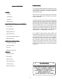
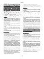
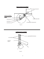
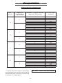
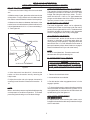
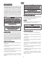
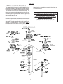
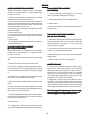
For Serial Numbers After - 08002609
Operator's Manual for
MODELS: KKW32121
KKW36121
KKW36141
KKW48141
KKH48151
Professional Quality Lawn Care Equipment
since 1945
Yazoo/Kees Power Equipment policy is to improve its products whenever it is
possible and practical to do so. In an effort to keep pace with changes in technology,
Yazoo/Kees reserves the right to make changes or improvements at any time without
incurring any obligation to make such changes on products previously manufactured.
MANUAL 103465 REV. 03(09/19/01)
INTRODUCTION
TABLE OF CONTENTS
This manual has been prepared for the operators of the
YAZOO/KEES KUTTER 32", 36" and 48" commercial
mowers. Read, understand, and follow the safety and
operating instructions.
SAFETY :
Training
Always stop the engine and blades, place the traction
levers in drive, and place the mower in gear when
leaving unattended.
Preparation
Operation
The steering system of this mower uses indvidual right
and left traction levers on the handle bars. Squeezing
the traction lever will reduce tension on the wheel drive
belt eliminating power to that wheel. With the opposite
wheel still under power a turn is accomplished. If the
traction lever is squeezed even tighter the brake will be
applied to that wheel and a tighter more abrupt turn is
accomplished. LEARN HOW TO USE THESE
IMPORTANT STEERING/BRAKE CONTROLS!
Maintenance
EQUIPTMENT SETUP AND ADJUSTMENTS :
Front casters
Axle adjustment
Cutting height chart
As an additional safety feature, these mowers are
equipped with an Operators Presence System. This is
an electrical interlock safety system which is activated
by depressing either one or both of the Operator
Presence Levers above the handle grips. Releasing
both Operators Presence Levers while mowing or
transporting will break the electrical circuit and cause
the engine and mower to stop. The mower will not stop
imediately after releasing the O.P. levers, some travel
does occur.
Brake adjustment
Operator presence switches
Belt adjustments
OPERATING INSTRUCTIONS :
Emergency stopping
Normal stopping
Pre-start
Operating instructions
SERVICE :
Interlock system
Cutting deck
Cutter housing
Belt replacement
!
Winter storage
WARNING
!
THE ENGINE EXHAUST FROM THIS
PRODUCT CONTAINS CHEMICALS
KNOWN TO THE STATE OF
CALIFORNIA TO CAUSE CANCER,
BIRTH DEFECTS OR
OTHER REPRODUCTIVE HARM.
Maintenance chart
2
SAFETY
WARNING: Failure to comply with the following
instructions may result in serious injury to the
operator or other persons. The owner must
understand these instructions, and must allow
only persons who understand these instructions
to operate the mower. Each person operating
the mower must be of sound mind and body and
must not be under the influence of any mind
altering substance.
If you have any questions pertaining to your
mower which your dealer cannot answer call or
write,
YAZOO/KEES POWER EQUIPMENT L.L.C., P.O.
Box 8, Beatrice, NE 68310 (402)-223-2391
7. Mow only in daylight or good artificial light.
8. Never operate mower in wet grass. Always be sure
of your footing; keep a firm grip on the handle and walk,
never run.
OPERATION
1. Do not change engine governor settings or overspeed
the engine.
2. Keep hands, feet, and clothing away from rotating
parts when operating mower.
3. Disengage blade drive when crossing gravel drives,
walks, roads or under any condition where thrown objects
might be a hazard.
4. After striking a foreign object or if mower vibrates
abnormally, stop the engine and disconnect the spark
plug. Inspect the mower for any damage and repair the
damage.
5. Stop the engine and wait for the blades to stop rotating
whenever you leave the operating position for any
reason, including emptying the grass catcher or making
any adjustments or repairs.
6. Mow across slopes, never up and down. Use caution
when changing direction on slopes. Always turn uphill.
Do not mow very steep slopes. Do not use sulky on any
slopes.
7. When parking mower, stop engine and leave drive
levers down in DRIVE position with transmission in gear
to prevent rolling. Never park mower on a slope.
8. NEVER OPERATE THIS EQUIPMENT, WITH
ENGINE RUNNING, IN AN ENCLOSED OR
CONFINED AREA WITHOUT PROPER VENTILATION
OF THE ENGINE EXHAUST.
TRAINING
1. Read this manual carefully and question your
dealer if something is not clear. Should the dealer be
unable or unavailable to answer your questions, call
or write our factory.
2. Be thouroughly familiar with the controls and proper
use of the equipment.
3. DO NOT allow children in the yard or area when the
mower is operating.
4. DO NOT allow pre-teenage children to operate
mower.
5. Allow only responsible teenagers with mature
judgment to operate mower and only when being
supervised.
6. Keep the area clear of all persons, particularly
small children and pets.
PREPARATION
1. The use of personal protective equipment, such as
(but not limited to) protection for the eyes, ears, feet
and head is highly recommended.
2. Never operate the mower without proper guards,
covers, safety switches and devices in place and
properly functioning. Inspect to determine that these
safety devices are installed properly, are in good
condition and operate properly. If the condition of any
of these devices is questionable, they must be
replaced or repaired before using the mower.
3. Thoroughly inspect the area and remove all stones,
sticks, wire and other debris. Also note other possible
hazards such as holes, stumps, sprinkler heads etc..
4. Do not operate the mower when barefoot or wearing
open shoes. Always wear substantial footwear and
long pants.
5. Fill gasoline tank before starting the engine. Only
use an approved gasoline container. Do not smoke
near open gasoline containers. Do not fill gasoline
tank indoors or when engine is running or hot. Wipe
off any spilled gasoline before starting engine.
6. Never attempt to make any adjustments (even the
smallest) when engine is running.
MAINTENANCE
1. Keep all nuts, bolts, and screws tight to keep mower
in safe operating condition.
2. Never store the mower with gas in the tank inside a
building where fumes can reach an open flame or spark.
Allow engine to cool before storing in an enclosure.
3. To reduce fire hazard, keep mower free of grass,
leaves, or excessive grease.
4. Check grass catcher assembly frequently for wear or
deterioration. Replace bag if loose seams or tears are
evident.
5.Have your mower inspected and serviced each year
by an authorized YAZOO/KEES dealer. Determine if
any additional devices are available which might upgrade
the saftey of your mower.
6. Use only authentic YAZOO\KEES replacement parts
to insure the saftey and quality of your mower is
maintained.
7. Saftey decals should be replaced if they are missing
or illegible. Decals may be purchased from your
YAZOO/KEES dealer or from YAZOO/KEES.
3
SETUP AND ADJUSTMENTS FOR
YAZOO/KEES KUTTER 32", 36" AND 48" COMMERCIAL MOWERS
FRONT CASTER WHEELS
1. Mount front caster wheel assemblies. Installation
includes fastening casters to front of the cutter deck
using 3/8 x 1" hex head capscrews.
THROTTLE INSTALLATION
1. Connect the throttle cable end to the throttle
mechanism on engine, leaving the cable clamp loose.
Push throttle lever on console completely forward. Then
pull the cable through the clamp on engine and tighten
the cable clamp. Move the throttle lever back and forth
to ensure proper installation.
FUEL TANK
1. Mount fuel tank to tank support. Secure with the two
tank straps, four 1/4" bolts, and four 1/4" nuts. Tighten
until snug, but do not over tighten or crush the tank.
GAS LINE INSTALLATION
1. The gas line is factory installed on the engine. Attach
loose end to fuel tank hose barb and secure with hose
clamp.
HANDLE ASSEMBLY
1. Align the upper mounting holes in handle with the
upper hole in the tank support.
2. Install two 3/8" x 1" screws through matched holes and
loosely install 3/8" nuts.
3. Align the lower holes and install hardware as above,
tighten upper and lower hardware.
POSITIONING THE FRONT CASTER SPACERS
1. Using the cutting height chart, find the correct number
of spacers to be placed under the caster swivel.
LINKAGE INSTALLATION
1. Install traction linkage to swivels in bellcrank mounted
to the tank support on each side of the mower. Traction
linkages are located on the upper handle, fastened to
the traction levers. To fasten linkage to swivel, first
disconnect linkage from traction levers, then screw
linkage into swivel. Reassemble linkage into traction
lever.
2. Install shifter to transmission with 1/4" x 1" screws.
The shifter is located in the inner box and hardware is
preassembled into the bracket on the transmission.
3. Install blade control rod into the bellcrank on the left
side of the tank support. Secure rod with ring type
retainer.
4. Refer to the section of this manual on adjustments for
the proper adjustment of the linkages you are
installing.The linkages were set at the factory but must
be checked before operating mower to insure of the
proper setting. Always check 100% of the adjustments
before you operate the mower.
5. Connect the two halves of the wiring harness together.
The four prong connectors have a locking tab that
shows which way to line them up and guarantees that
they are connected properly when the lock snaps.
6. Install the chute deflector to the side of the mower
deck. Bolt it into place using the two 5/16" x 1" screws and
nuts preassembled into the mounting tabs on the deck.
Tighten the screws very securely with the chute
completely covering the discharge opening and tight
against the side of deck.
2. Remove the lynch pin and washer from the top of
caster and reposition spacers to the desired cutting
height from the chart. See figure # 2
AXLE HEIGHT ADJUSTMENT
1.To adjust rear axle, stop engine and place drive
levers in the neutral lock position, remove spark plug
wire.
2. Remove lower belt shield from underside of rear deck
for better access to axle adjustment bolts.
3. Loosen axle pivot bolts and axle adjustment bolts.
See figure # 1.
4. Place a jack under center of rear deck raise the jack
slightly so axle adjustment bolts may be removed.
5. With the jack raise or lower the rear deck to the desired
position using the chart to ensure proper height. Reinstall
the axle adjustment bolts and tighten.
A tapered punch may be used to help align the holes.
See figure #1.
NOTE:
It may be necessary to readjust drive and brake linkages.
NOTE:
To achive the best quality cut, the blades should be
level with the ground or slightly tipped forward.
4
REAR AXLE HEIGHT ADJUSTMENT
AXLE PIVOT BOLTS
AXLE ADJUSTMENT
BOLTS
POSITION A
PLACE JACK HERE
POSITION B
POSITION C
LOOSEN BOLTS EACH SIDE
POSITION D
Figure 1
CASTER HEIGHT ADJUSTMENT
MACHINERY BUSHING
1/2" SPACERS
CASTER
SWIVEL
Figure 2
5
SETUP AND ADJUSTMENTS FOR
YAZOO/KEES KUTTER 32", 36" AND 48" COMMERCIAL MOWERS
CUTTING HEIGHT ADJUSTMENT CHART
AXLE
POSITION
NUMBER OF
SPACERS BELOW
CASTER ARM
NUMBER OF 1/4" BLADE SPACERS
UNDER CUTTER HOUSING
4
3
2
1
0
4
3
2
1
0
4
3
2
1
0
4
3
2
1
0
4
3
2
1
0
4
3
2
1
0
4
3
2
1
0
4
3
2
1
0
0
A
1
2
B
3
3
C
4
4
D
5
CUTTING HEIGHT
(IN INCHES)
1 1/2
1 3/4
2
2 1/4
2 1/2
1 3/4
2
2 1/4
2 1/2
2 3/4
2 1/2
2 3/4
3
3 1/4
3 1/2
3
3 1/4
3 1/2
3 3/4
4
3 1/4
3 1/2
3 3/4
4
4 1/4
3 1/2
3 3/4
4
4 1/4
4 1/2
3 3/4
4
4 1/4
4 1/2
4 3/4
4
4 1/4
4 1/2
4 3/4
5
USE ONLY 4 BLADE SPACERS MAXIMUM
1. To quickly achive small changes in cutting heights,
move the spacers from under the cutter housing to
above the cutter pulley. (Each spacer moved will give
an additional 1/4" of cutting height ).
6
SETUP AND ADJUSTMENTS FOR
YAZOO/KEES KUTTER 32", 36" AND 48" COMMERCIAL MOWERS
BRAKE / TRACTION ADJUSMENT
1. Disconnect the brake linkage from the brake band
arm.
OPERATOR PRESENCE SWITCH ADJUSTMENT
The operator presence switches can be adjusted by
loosening the screws on the side of the O.P. lever
linkage and sliding the switch up or down. The O.P.
switch should have a 1/32" to 1/16" gap between the
plunger and the bottom side of the control panel when
operator presence levers are released.
2. With the mower in gear, place the traction levers in the
drive position. Firmly pull back on the handles until the
tires slide to seat the wheel drive belts into the pulleys.
3. Measure the clearance between the bottom of the
traction lever rod and the bottom of the thumb latch slot.
It should be between 3/16" to 1/4", but not exceeding 1/
4". See Figure # 3
BLADE SWITCH ADJUSTMENT
The blade engagement switch can be adjusted by
loosening the screws on the flange under the control
panel and moving the switch in or out. The blade switch
should be adjusted so the plunger is fully depressed
when the engagement lever is fully disengaged.
O.P. LEVER
HANDLE
ADJUSTMENTS - DRIVE BELTS
For all drive belts, tension should be set so that belt
vibration is minimized or eliminated when belts are
moving during normal operation. A properly tensioned
belt should have 1/4" to 3/8" deflection at the center of
belt span between pulleys when blades are engaged.
Blade drive belt tension is pre-set at the factory.
THUMB LATCH
NOTE:
DO NOT over tighten belt. Excessive tension will
decrease belt and spindle bearing life.
TRACTION
LEVER
BLADE DRIVE BELT ADJUSTMENTS
WARNING
BEFORE PERFORMING ADJUSTMENTS ON
BLADE BELT, TURN MOWER OFF, CLOSE FUEL
VALVE, AND DISCONNECT SPARK PLUG WIRE.
3/16" to 1/4" CLEARANCE
Figure 3
4. If the clearance is less than 3/16", disconnect the
traction rod from the traction lever by removing the
hairpin cotter.
1. Remove front deck belt shield.
2. Loosen whiz nut on turnbuckle.
5. Adjust the traction rod to the proper clearance by
screwing it out of the swivel if clearance is less than 3/
16".
3. Set belt tension when engagement lever is in the
engaged position.
4. To increase belt tension rotate turnbuckle toward the
rear of the mower until desired tension is gained. Do not
over tighten belts, to much tension will reduce belt and
spindle bearing life. See figure # 6
NOTE:
More or less brake pressure may be desired depending
on the operator or conditions of operation. To increase
pressure tighten the wing nut on the brake linkage.
AUXILIARY BLADE DRIVE BELT
(48" MODELS ONLY)
To adjust tension of the auxiliary belt rotate nut on
linkage that is attached to deck strap located on the right
side of cutter deck.
7
SETUP AND ADJUSTMENTS FOR
YAZOO/KEES KUTTER 32", 36" AND 48" COMMERCIAL MOWERS
TRANSMISSION DRIVE BELT
To increase the tension of the transmission belt, loosen
the nut on the underside of the transmission idler pulley
located under the rear deck, slide the idler assembly
inward to increase tension and tighten the nut to secure.
See figures 4 & 5.
BLADE ENGAGEMENT LEVER
The blade engagement lever needs to be adjusted so
the lever does not come in contact with control panel
when the lever is in the off position.
BELT GUDIES
Belt guides under rear deck are adjusted as shown in
figures 4 and 5
To adjust, remove the clevis pin from the yoke and
adjust by turning the yoke. The clevis pin connects the
blade engagement lever to the yoke, and the yoke is
connected to the blade engagement rod that runs to the
bellcrank on the rear deck.
NOTE:The blades should come to a stop from
maximum speed within 7 seconds after
disengaging.
32" & 36" MODEL
48" MODEL
1/4" CLEARANCE
1/2" 102036
ENGINE
PULLEY
1/8" CLEARANCE
103462
TRANSMISSION BELT
103463
1/2" 102036
ENGINE
PULLEY
103462
TRANSMISSION BELT
103462
1/8" CLEARANCE
1/8" CLEARANCE
TRANSMISSION IDLER PULLEY
TRANSMISSION IDLER PULLEY
Figure 4
Figure 5
AUXILARY BELT ADJUSTMENT
ROD
TURNBUCKLE
1/4"
IDLER PIVOT POINT
ENGAGEMENT IDLER
ASSEMBLY
Figure 6
8
OPERATING INSTRUCTIONS
BEFORE OPERATING
Be thoroughly familiar with all controls and how to use
them before operating the mower. Know beforehand
how to stop the engine, drive wheels, and mower blades
in preparation for possible emergency.
PRE-START CHECKLIST
Make the following checks and perform the services as
required before each start up.
1. If required make cutting height adjustments and drive
linkage adjustments. Refer to pages 5 and 6
EMERGENCY STOP
Pull both traction levers firmly against handle grips and
hold them securely in place. Use thumb latches to lock
both traction levers in neutral position, then stop engine
by pulling throttle control back to the off position. See
figure # 7
O.P. LEVER
2.Check tires for proper inflation (front caster tire pressure
to be 50 lbs max. / rear tire pressure to be 14 lbs max.
3. Check guards, deflectors, and covers to make sure
all are in place and secure.
4. Check blade belts for wear and correct tension if worn
or damaged, replace with original part.
THUMB LATCH
5. Clean interior and exterior surfaces of the cutting deck
and clean engine of any accumulation of dirt or debris.
Keep engine air intake clear at all times.
HANDLE
POINT
6. Check engine oil add if needed (do not overfill)
refer to engine manual for oil specs.
7. Add fuel to tank after pushing the mower outside
where fumes can dissipate. Make sure cap is tight after
refueling.
THUMB LATCH
NEUTRAL POSITION
TRACTION LEVER
Figure 7
NOTE
DO NOT ADD FUEL WHILE ENGINE
IS RUNNING OR WHILE ENGINE IS HOT.
NORMAL OPERATING STOP
1. Pull both traction levers firmly toward the handle grips
to stop forward motion.
NOTE
USE FRESH, CLEAN, LEAD FREE
GASOLINE. DO NOT USE GASOLINE
THAT HAS BEEN STORED FOR LONG
PERIODS. LEADED GASOLINE OR
GASOHOL IS NOT RECOMMENDED.
2. Use thumb latches to lock traction levers in the neutral
position.
3. Move the throttle control to the slow position.
4. Move blade engagement lever to the off position.
5. Move shift lever to the neutral position.
STARTING AND OPERATING
ENGINE: START ENGINE AS FOLLOWS:
1. Move blade engagement lever to the off position so
the interlock will allow engine to start.
6. Stop engine by pulling throttle control lever all the way
back to the off position.
2. Check gear shifter to be sure it is in the neutral position.
NOTE
CLOSE FUEL VALVE AT THE END OF
EACH MOWING JOB !!
3. While on level terrain, lock both traction levers into the
neutral position.
4. Open fuel shut-off valve
5. Set throttle control all the way forward to the choke
position.
9
OPERATING INSTRUCTIONS
6. Pull starter rope until engine starts.
7. Warm engine momentarily, then move the throttle
control out of the choke position until engine runs
smoothly, approximately 1/2 throttle. Engage the blades
and set the desired rpm. The best cutting and bagging
is obtained with engine at or near top rpm.
NOTE: DO NOT engage the blades at full rpm. To
extend belt life engage and disengage belts at 1/
2 throttle.
8. Depress one operator presence lever and shift
transmission to the desired gear.
9. Unlock the traction levers by pushing the thumb
latches forward. Slowly release both traction levers at
the same time to begin forward motion.
10. The steering system of this mower uses indvidual
right and left traction levers on the handle bars. Squeezing
the traction lever will reduce tension on the wheel drive
belt eliminating power to that wheel. With the opposite
wheel still under power a turn is accomplished. If the
traction lever is squeezed even tighter the brake will be
applied to that wheel and a tighter more abrupt turn is
accomplished. - turn left by squeezing the left hand
traction lever or turn right by squeezing the right hand
traction lever. If you squeeze both levers the mower will
stop.
10
SERVICE
SERVICE ASSISTANCE REPLACEMENT PARTS
To retain the quality of your mower, use genuine YAZOO/
KEES replacement parts only. Contact your local
YAZOO/KEES dealer for parts and service assistance.
For the correct part or information for your particular
mower, always mention model and serial number. We
recommend returning your mower to an authorized
YAZOO/KEES dealer on a yearly basis for inspection
and addition of any new devices which might upgrade
the performance and saftey of your mower. For engine
parts and service, look in the yellow pages for the engine
manufacturer's dealers under the heading engines gasoline.
WARNING
BEFORE PERFORMING SERVICE ON THE
MOWER TURN ENGINE OFF, CLOSE THE FUEL
VALVE, AND DISCONNECT THE BATTERY AND
ALLOW ENGINE TO COOL. DISCONNECT THE
SPARK PLUG WIRE. IF THE MOWER IS TO BE
RAISED OR TILTED, MAKE SURE TO SECURE
THE MOWER IN PLACE.
NOTE
ALL MOWERS SHOULD BE TILTED WITH
THE CARBURETOR SIDE UP
MODULE SYSTEM
The interlock modules function is to prevent the engine
from starting if the blade and/or traction systems are
engaged. It also causes engine shutdown if the operator
falls from, or attempts to leave the operator position
while the blades or traction drives are engaged. After
the engine starts, the operator must hold either the left or
right O.P. lever down before engaging the blades or
shifting the transmission into gear. If niether O.P. lever is
held the engine will stop.
INTERLOCK SAFTEY SYSTEM
Check the function of the safety electrical system on a
regular basis.
1. Engine must kill if blades are engaged without O.P.
levers held down.
2. Engine must kill if transmission is taken out of neutral
without holding down O.P. levers.
3. Engine must not start unless blades are off and
transmission is in the neutral position.
4. Do not operate the mower if the interlock saftey
system allows operating or starting in any unsafe
condition.
CAUTION
DO NOT BY-PASS THE INTERLOCK SWITCHES
THEY ARE FOR YOUR PROTECTION! CHECK
THE OPERATOR PRESENCE SYSTEM DAILY
ALONG WITH THE TRACTION DRIVE SWITCHES
AND BLADE SWITCH FOR PROPER OPERATION.
REPAIR IMMEDIATELY IF A
PROBLEM IN THE SYSTEM IS FOUND. DO NOT
OPERATE MOWER IN A DAMAGED CONDITION.
NEUTRAL LOCK THUMB LATCH
The point between neutral and drive on the slot of the
thumb latches should be checked every 50 hours. If the
point is rounded it should be replaced.
See figure 7 on page 9.
BLADES
If blades are in good condition, sharpen at an angle of
22 to 28 degrees about 2-1/2" in from the tips.
NOTE
AFTER SHARPENING, CHECK BLADES FOR
PROPER BALANCE, IF NEEDED CORRECT
BALANCE TO PREVENT EXCESSIVE VIBRATION
CUTTING DECK SERVICE
If mower is cutting improperly, check the following:
1. Ground speed - too fast for proper cutting. Shift to a
lower gear.
2. Engine speed - too low for proper cutting. Increase
engine speed.
3. Cutting height - too low for ground/grass conditions.
Adjust to higher cut.
4. Blade spacers - not positoned properly on all blade
shafts. Visually inspect and replace or adjust as
necessary.
5. Front casters - spacers not in correct relationship with
rear axle. Adjust as necessary.
6. Belt slippage - causing bad cutting pattern or uneven
cut. Adjust belt tension
7. Tire pressure - uneven tire pressure can cause an
uneven cut from one side of the deck to the other.
Equalize tire pressure.
11
SERVICE
CUTTER HOUSING SPINDLE ASSEMBLYS
The cutter housing assembly is designed with a slip fit
Cutter housing assemblys use sealed bearings and
inner race and pulley. The sole purpose of the setscrew
are maintance free.
in the pulley is to hold the housing assembly together.
The setscrew is not ment to secure the pulley. The
pulley is secured by pinching the pulley to the inner race
NOTE
of the bearings using the blade bolt and nut. Tighten the
WHEN
PRESSING
A
BEARING IN OR OUT OF A
setscrews after you have pinched the assembly together
CUTTER
HOUSING
APPLY CONSTANT
with the blade bolt and nut.
PRESSURE TO THE RACE OR RACES THAT
HAVE AN INTERFERENCE FIT.
Each cutter spindle on 48" Models have a different stack
NEVER
BEAT A BEARING IN OR OUT.
up of spacers and pulleys, to achieve proper belt
alignment. The left cutter spindle on 48" Models is the
same as 32" and 36" Models. See figure #8 (Refer to
the Kutter parts manual when ordering parts.)
12
SERVICE
WHEEL DRIVE BELT REPLACEMENT
WHEEL DRIVE BELT: If belts are worn or damaged,
wheels will not drive properly. To replace either belt,
proceed as follows:
1. Unhook brake linkage from brake band arm. Located
between the rear deck and the rear tire.
2. Unhook traction linkage from bellcrank. The traction
linkage connects the traction levers on the handle to the
bellcranks on each side of the mower. The bellcranks
are located behind the rear tires.
3. Unhook spring from belt guard. Located on the sides
of the tank support.
4. Remove belt guard.
5. Loosen bellcrank pivot and belt guard mounting
bolts, slide spacers off of bolts to gain clearance for belt
removal.
6. Remove belt.
7. To replace belt reverse the procedure and make any
needed adjustments.
BLADE DRIVE BELT REPLACEMENT
(32", 36" & 48" MOWERS)
BLADE DRIVE BELT: If the belt is worn or damaged,
blades will not drive properly. To replace this belt,
proceed as follows:
1. Close fuel tank shut-off valve and remove spark plug
wire.
2. Remove the belt cover from the mower deck.
3. Loosen the snubber bolt on the engagement idler so
belt can be removed. The engagement idler is located
on the front deck towards the rear. See figure 6 on page
8.
4. Raise the rear of mower and block up the rear tires to
gain access to the underside of rear deck.
5. Remove the rear belt shield from the underside of rear
deck.
6. Loosen the engine bolts with belt guides and rotate
them away from the engine pulley. Belt guides can be
seen in figures 4 and 5 on page 8.
7. Loosen the belt guides located around the pulleys on
the front deck. Belt guides are 5/16" bolts and must be
loosened to remove the belt.
AUXILARY BELT REPLACEMENT
(48" MOWERS)
1. Loosen the auxilary belt adjusting rod. To relieve
tension on the belt. See figure 6 on page 8.
2. Remove belt guides from the center spindle.
3. Remove belt.
4. Reverse procedure for replacement. Adjust belt to
proper tension.
TRANSMISSION BELT REPLACEMENT
(32", 36" & 48" MOWERS)
1. Blade drive belt must be removed from engine pulley
before transmission belt can be removed. See blade
drive replacement, use steps 4, 5, and 6. Also see
figures 4 and 5 on page 8.
2. Loosen nut on the transmission idler pulley and slide
pulley in slot to relieve tension on belt.
3. Remove the belt from the transmission pulley and the
engine pulley.
4. Reverse the procedure for replacement.
WINTER STORAGE
To prepare your Yazoo/Kees mower for winter storage,
perform the routine maintenance and necessary
adjustments and record the part numbers of worn or
broken parts so they may be ordered and replaced
before the next mowing season. Use only authentic
Yazoo/Kees replacement parts to insure proper fit and
the saftey of your mower is maintained.
Treat the fuel in the tank with a fuel stablizer (such as
STA-BIL). This will minimize the formation of fuel gum
deposits during storage. Read and follow the mix ratio
on the container. Run the engine for at least 10 minutes
after adding the stablizer to bring it into the carburetor.
These few tips will help make your mower ready
when needed for the next mowing season and
insure many years of dependable service.
8. Remove belt.
9. To replace belt - reverse the procedure and make
any needed adjustments to belt guides or belt tension.
13
MAINTENANCE CHART
ITEM
FREQUENCY
REQUIRED SERVICE
REAR TIRES
BEFORE EACH MOWING
FRONT TIRES
INFLATE TO PROPER
PRESSURE
BEFORE EACH MOWING
AFTER EACH MOWING
INFLATE TO PROPER
PRESSURE
DAILY
REMOVE GRASS & DEBRIS
UNDERSIDE OF REAR DECK
AFTER EACH MOWING
INSPECT FOR CRACKS/LOOSE
HARDWARE
BLADE PULLEYS
WHENEVER REMOVED
REMOVE GRASS & DEBRIS
ENGINE PULLEY
WHENEVER REMOVED
LOCTITE TO SHAFT
FRONT WHEEL BEARINGS
DAILY
ANTI-SEIZE TO SHAFT
CASTER SHAFTS
DAILY
LUBE WITH GREASE
ENGINE OIL LEVEL
DAILY/CHANGE PER MANUAL
LUBE WITH GREASE
REAR WHEELS
DAILY
FILL AS NEEDED
BRAKE ARMS
DAILY
LUBE WITH GREASE
BLADE ENGAGEMENT
BELLCRANK
DAILY
LUBE WITH GREASE
UNDERSIDE OF MOWING DECK
MOWER DECK
TRANSMISSION SHAFTS
BLADES
LUBE WITH GREASE
WEEKLY
EVERY SHARPENING
LUBE WITH GREASE
100HRS. PAPER/25HRS FOAM
REPLACE IF DAMAGED
LINKAGES AND ADJUSTMENTS
100 HRS.
SERVICE PER MANUAL
FUEL FILTER (IN-LINE)
100 HRS.
INSPECT & REPLACE IF WORN
OR DAMAGED
ENGINE AIR FILTER
POINT ON THUMB LATCH
BETWEEN NEUTRAL AND
DRIVE
WINTER STORAGE
DRIVE WHEEL IDLER ARMS
250 HRS/REPLACE EACH
MOWING SEASON
REPLACE WITH NEW
IF POINT WORN, REPLACE
THE END OF MOWING SEASON
DAILY
SEE SECTION ON STORAGE
LUBE WITH GREASE
14
Yazoo/Kees Limited Two Year Warranty
1.
This Limited two-year Warranty is issued by Yazoo/Kees Power Equipment, only to the original
purchaser. The warranty period is limited to ninety (90) days when product is or has been used
for rental purposes.
2.
Yazoo/Kees warrants that all new equipment manufactured by Yazoo/Kees (Yazoo/Kees Products), listed in paragraph 9 hereof, shall be free of defects in material and workmanship for the
term described in paragraph 4 below. Component parts, equipment, and accessories not manufactured by Yazoo/Kees are not warranted hereunder, but are warranted by the original manufacturer only to the extent of any original manufacturer’s warranty, with the exception of the
following; two years on wheel motors, ninety days on belts, hoses, tires, and battery, one year
on electrical components, and one year on Peerless model 700 transmissions (first ninety days
warranted by Peerless, remainder by Yazoo/Kees).
3.
In the event that any Yazoo/Kees Product warranted hereunder shall be defective or fail to
conform with this limited warranty, Yazoo/Kees shall, subject to the provisions hereof, pay for,
or provide labor and materials for, the repair or replacement of such defective Yazoo/Kees
Product.
4.
This limited warranty is for two years (24 months) from purchase date for Yazoo/Kees Products.
5.
To obtain limited warranty service on a Yazoo/Kees Product use this procedure:
a.
b.
c.
d.
e.
6.
Locate the nearest Yazoo/Kees dealer or distributor.
If you have moved, notify any Yazoo/Kees dealer or distributor in your area. You must
be able to confirm purchase date to validate your warranty.
Make arrangements to have the equipment delivered to the dealer or distributor (refer
to paragraph 6a).
If you have questions concerning the Yazoo/Kees Limited Warranty, they should be
referred to :
Yazoo/Kees Power Equipment
P.O. Box 8
700 Park Street
Beatrice, NE 68310
Attention: Customer Service Department
(402) 223-2391
Warranty service on Yazoo/Kees Products must be performed by an authorized Yazoo/
Kees dealer.
This limited warranty does not cover the following:
a.
Transportation to and from the Yazoo/Kees dealer or distributor.
15
b.
c.
d.
Normal maintenance services and normal maintenance items such as brakes, brake
shoes, spark plugs, oil, air filters, mower blades, gauge wheels, skids and other wear
items.
Any Yazoo/Kees Product which had been altered or modified in any way.
Any repair or replacement caused by customer neglect or lack of maintenance. (The
purchaser is responsible for making sure that Yazoo/Kees Products are operated and
serviced as directed in the applicable manual or service instruction. Incorrect use or
maintenance will void this Limited Warranty.
7.
YAZOO/KEES MAKES NO OTHER EXPRESS OR IMPLIED WARRANTY, OR WARRANTIES AS TO THE MERCHANTABILITY OR FITNESS FOR A PARTICULAR PURPOSE.
ALL WARRANTIES ARE LIMITED IN DURATION TO THE TERMS SET OUT IN PARAGRAPH 4, ABOVE. YAZOO/KEES SHALL HAVE NO LIABILITY FOR ANY INCIDENTAL
OR CONSEQUENTIAL DAMAGES RESULTING FROM THE BREACH OF ANY WARRANTY, INCLUDING, BUT NOT LIMITED TO, LIABILITY FOR INCONVENIENCE,
RENTAL OR PURCHASES OF REPLACEMENT EQUIPMENT, OR FOR LOSS OF PROFITS OR OTHER COMMERCIAL LOSS. SOME STATES DO NOT ALLOW A LIMITATION ON HOW LONG AN IMPLIED WARRANTY LASTS, SO THE ABOVE STATEMENT
MAY NOT APPLY TO YOU. SOME STATES DO NOT ALLOW THE EXCLUSION OR
LIMITATION OF INCIDENTAL OR CONSEQUENTIAL DAMAGES, SO THE ABOVE
LIMITATION OR EXCLUSION MAY NOT APPLY TO YOU.
8.
This warranty is not subject to change or modification by anyone, including Yazoo/Kees dealers
or distributors, and no Yazoo/Kees dealer or distributor is authorized to make any representations on behalf of Yazoo/Kees Power Equipment.
Note: This Warranty is for the following machines or products:
• ZTMax Midmount Riding Mowers
• Kutter Midsize Walk-behind Rotary Mowers
• Power Rake Dethatchers
• Power Slicer Aerators
• Core Plugger Aerators
• Classic High-wheel Walk-behind Rotary Mowers
16
17