1
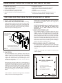
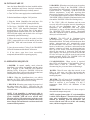
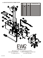
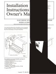
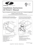
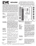
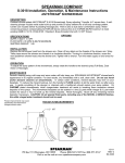
Installation
Instructions &
Owner's Manual
C
UL
R
US
This symbol on
the product means
the product is
listed by
Underwriters
Laboratories, Inc.
AUTOFLO ELECTRONIC STEAM UNIT - POWER HUMIDIFIER
MODELS S2000 AND S2020
FOR GAS OR OIL FORCED AIR FURNACES, HEAT PUMPS AND ELECTRIC FURNACES
The AutoFlo Power Humidifier you have purchased has
been designed to be simple to operate and maintain.
Familiarizing yourself with the items listed in Figures 1
and 2 will assist you in installing and maintaining your
Steam Power Humidifier.
WATER PAN
WATER INLET
TANK BAFFLE
WATER LEVEL
PROBE
WATER INLET
FOR DRAIN
VALVE DETAILS
SEE FIG. 8
BLOWER
INTERLOCK &
HUMIDISTAT CONN.
HEATER
TEMPERATURE PROBE
OVERFLOW
"T" ADAPTER
STATUS LIGHTS
AUTO DRAIN CONN.
MANUAL WATER DRAIN
FIG. 1
Parts included in the Steam Humidifier package are:
1. Humidifier
2. Self Piercing Saddle Valve
3. Installation Instructions and Owners Manual
4. Mounting Template
5. Installation Hardware package
6. Insulation and tape
7. Automatic Drain Assembly
8. Humidistat - Autoflo Models 062000
FIG. 2
Options and additional parts recommended:
1. Overflow/drain lines - 5/8"ID & 3/8"ID high temperature hose
2. 2 hose clamps - 1" and 1/2"
3. Electrical wiring and connections
4. Water Hammer Arrester #WH 100
5. Zinc Anode #Z 100
SIMPLIFIED INSTALLATION INSTRUCTIONS
1. Insulate the water reservoir.
2. Select the mounting location on the duct and tape
on the mounting template.
3. Punch or drill the (8) 1/8" mountings holes.
4. Cut out the humidifier opening in the duct.
5. Insert the humidifier into the opening and screw in
place.
6. Connect the water line.
7. Connect an overflow line and automatic drain line.
8. Make 24 VAC electrical connections to blower
interlock.
9. Install and connect the humidistat.
10. Plug power cord into a grounded dedicated 120 VAC, 15
amp outlet for S2000 (240 VAC, 10 amp for S2020).
DETAILED INSTALLATION INSTRUCTIONS
mounting plate. The fiberglass duct alone will not support the
weight of the steam humidifier, which is 9 Lbs. empty and 15
Lbs. when full of water.
1. INSULATE WATER RESERVOIR
With insulation foil side down, remove adhesive backing.
Align humidifier so that front side of unit meets long edge of
insulation. Fold insulation up onto sides of humidifier and
press firmly. Cut and apply 5 continuous strips from the tape
provided to seal the foil as shown. The tape will prevent the
sharp duct edges from damaging the foil.
NOTE: The Humidifier must be installed at a location
so that the 120 VAC (240 VAC for S2020) power
connections can be made without the use of an
extension cord.
3. MOUNTING TEMPLATE
USE TAPE TO SEAL
THE OUTSIDE EDGE
OF THE FOIL
(2 PLACES)
Two mounting templates are provided. Choose the correct
template for your mounting method. Tape the mounting
template to the duct. The template must be leveled using the
top of the cutout on the template. The template should be
located so that the bottom of the reservoir cut-out is flush with
the inside of the bottom of the duct for horizontal duct. Since
most ducts are insulated this additional space, about one (1)
inch, must be accounted for when determining the location
for the bottom of the reservoir cut-out. If you are mounting it
under the duct, make sure the duct is level.
INSULATION
(FOIL SIDE OUT)
4. DRILL HOLES AND CUT OPENINGS
Use an electric drill, with grounded power cord, to drill eight
(8) mounting holes, 1/8" diameter, in the duct. These can be
drilled through the template at the locations indicated on the
template.
USE TAPE TO SEAL THE FOIL
TO THE FRONT MOUNTING PLATE
(3 PLACES-SIDES AND BOTTOM)
FIG. 3
FRONT MOUNTING PLATE
A saber saw or tin snips can be used to cut out the water
reservoir opening.
2. LOCATION
The steam humidifier can be installed in either warm air
supply or the cold air return ducts; however the preferred
location would be in the warm air supply duct of the heating
system. This humidifier does not require warm air to
evaporate the water in order to provide humidity, but it will
operate more efficiently in the warm air duct and less
condensate is likely to form.
CUT ON LINE
MOUNTING TEMPLATE
CUT ON LINE
1. TAPE TEMPLATE IN LEVEL POSITION.
2. DRILL (8) HOLES FOR SHEET METAL SCREWS
SHOWN ON TEMPLATE (DO NOT DRILL LARGER
THAN 1/8" DIAMETER.
CUT ON LINE
MODEL S2000 & S2020
When selecting a location on the duct, be certain that there is
enough room in the duct for the water reservoir. There should
be at least five (5) inches above the reservoir and the reservoir
should not occupy more than about 25 percent of the duct
space. If this criteria can not be met, you should install the unit
under the duct by means of the tank flange. A template is
provided for installing the unit under the duct, on the cold air
return.
3. CUT OUT SOLID LINE AREA AS MARKED.
4. MOUNT HUMIDIFIER PER INSTRUCTIONS.
If the humidifier is installed on fiberglass duct, the installer
must provide some structural support for the
CUT ON LINE
FIG. 4
P/N 094021B0037
2
A temperature sensor is mounted in the water reservoir of the
humidifier. As the water temperature increases to about 170
degrees F, the computer closes a set of blower relay contacts.
When the water cools to about 140 degrees F, the computer
will open the relay contacts.
5. WATER CONNECTIONS
A. WATER SUPPLY USING THE SADDLE VALVE
FURNISHED WITH UNIT
Installation instructions for the saddle valve are printed on
the plastic bag containing the saddle valve and its
components. Tap into a 1/2” or 3/4” domestic hot water
line for best results, but a cold water line will do. Avoid
connecting to water lines from a Reverse Osmosis system.
8. WIRING THE STEAM HUMIDIFIER
A. INSTALLING AND WIRING THE HUMIDISTAT
NOTE: Never install the saddle valve on the bottom of the
water pipe. Sediment in the water pipe may clog the
saddle valve. When tightening the hex compression nut,
tighten only enough to assure there are no leaks.
NOTE: Saddle valves do not meet plumbing codes in
some areas. A “T” fitting with a valve may be required to
meet code or, if low water pressure causes frequent water
alerts on the steam humidifier.
A humidistat, such as the AutoFlo Models 052000 or
062000, is required to control the Steam Humidifier. The
humidistat may be installed on the wall in the living space
or on the return air duct. NOTE: Continuos fan operation
should be initiated if the humidistat is installed on the
return air duct! Instructions for installation are packaged
with the humidistat.
DO NOT connect any foreign voltage to the “H” terminals
of the humidifier. The unit supplies it’s own 24 volt
control voltage. Simply connect the two “H” terminals
straight to the humidistat terminals.
NOTE: Do not use any line which is served by a water
softener. If your home has a water softener, make the
water connections to a water line upstream from the water
softener. A water softener is not a demineralizer. It merely
exchanges various hard ions for soft ions in the water.
These soft ions, or minerals, will build up in the
humidifier, causing the need for frequent servicing. The
evaporation of softened water may also produce a white
powder which may be carried into the duct system and,
ultimately, into your home.
S2000 & S2020 Typical Wiring
and Blower Interlock Diagram
S2000 & S2020 Humidifier
Typical
Thermostat
Note: Use a water hammer arrester (WH-100) if water
spikes occur during operation.
R W G
Y
R W G
Y
G1 R G2 H
H
B. OVERFLOW & DRAIN LINES
The use of an overflow line and drain line is always
required.
Use 5/8" ID high temperature tubing, such as automotive
heater hose or dishwasher drain hose. Slip the hose over
the 5/8" drain fitting and use a hose clamp to secure. Use
3/8" high temperature tubing for the automatic drain
connection. Slip the hose over the 3/8" adaptor fitting and
use a hose clamp to secure.
Route the hoses to a suitable drain. DO NOT route the
hoses above the humidifier. Failure to install the drain
lines will result in water leaks during normal operating
conditions.
Furnace
FIG. 5
Humidistat
Heat & Cool System
B. FIELD WIRING
All wiring must be made in accordance with local codes
and ordinances. DO NOT cut off the grounded plug
and/or hard wire this unit to line voltage.
6. MOUNTING THE STEAM HUMIDIFIER
Figures 5 & 6 describes the suggested interlock wiring
arrangement for HVAC systems. Interlocking may be
performed on heating systems that provide a 24 VAC NEC
Class ll terminal for blower control.
Place the humidifier reservoir into the opening in the duct and
secure with eight (8) sheet metal screws.
NOTE: If the ductwork will not support the unit in a level
position with the water pan full of water, the duct-work
must be reinforced. Both steam models weigh
approximately 9 Lbs. empty and approximately 15 Lbs.
full of water.
The blower relay (G) circuit is connected to the low voltage
terminals on the humidifier, Figure 5. The relay contacts
must be used to interlock the system blower.
IMPORTANT NOTE:
If the Steam Humidifier is removed and
disconnected from the system, the blower
interlock circuit must be restored to it's original
configuration.
7. STEAM OPERATION
Because of the high output of this Humidifier, it must not
be operated in ducts or plenums without the blower
operating. The steam humidifier is designed to be
"Dominant" over the Heating-Air Conditioning System
Blower. The "System" blower will be operated by the
humidifier when humidity is required to meet the
humidistat setting.
3
9. SETTING THE HUMIDISTAT
S2000 & S2020 Humidifier
Heat only
Thermostat
R W
G1 R G2 H
It is recommended that humidistat settings of 30-40% not be
exceeded. If condensation is noticed on windows during
very cold outside temperatures, the humidistat setting should
be lowered.
H
The maximum recommended relative humidity for your
home depends upon factors such as outdoor air temperature,
type and placement of insulation, vapor barriers,
effectiveness of weather stripping, type of windows and
doors (including frames and jambs) and whether or not storm
windows and doors are used. With all these variables it is
nearly impossible to recommend a proper humidity setting.
The best humidistat setting is one that you are comfortable
with. Also, as the outdoor temperature fluctuates, it may be
necessary to adjust the humidity level of your system a few
times during the heating season.
R W G
Furnace
FIG. 6
Humidistat
Heat Only System
Refer to the "Relative Humidity Chart" as a starting point for
your proper humidistat setting. Generally, in a tighter and
better insulated house, the humidistat may be set higher than
in a drafty, un-insulated house.
Connect field wiring as shown in Figures 5 or 6.
IMPORTANT: If the humidistat, controlling the
humidifier, is installed on the return air plenum, it must be
located at least three (3) feet upstream from the furnace or
heat pump. If the humidifier is installed in the return air
plenum the humidistat must be located at least three (3) feet
upstream from the humidifier.
The humidistat has two (2) screw terminals which should be
connected to the low-voltage interlock plug. (Figure 5).
RELATIVE HUMIDITY CHART
Outside
Relative
Humidity
Indoor Relative
Humidity
When Outside
Air Is Heated To
72 Degrees F
-10 Deg. F
40%
60%
80%
1%
2%
2%
20%
0 Deg. F
40%
60%
80%
2%
2%
5%
25%
10 Deg. F
40%
60%
80%
4%
5%
7%
30%
20 Deg. F
40%
60%
80%
6%
8%
11%
35%
30 Deg. F
40%
60%
80%
8%
13%
17%
35%
Outside
Temperature
4
Maximum Safe
Recommended Indoor
Relative Humidity
10. INITIAL START-UP
D. BLOWER: When the water in the reservoir reaches
approximately 170 deg. F. the "BLOWER" LED will
be illuminated and the interlock wiring should turn the
system blower on. Depending upon the water and
ambient temperatures, it may take anywhere from
four to twelve minutes for the water to heat to 170 deg.
F. If the humidistat remains closed the "HEATER" and
"BLOWER" LED's will both be illuminated at the same
time and the "POWER" LED will be blinking slowly.
Once the Steam Humidifier has been installed and the
water, humidistat and blower interlock connections
completed, the humidifier may be initially started.
A. Turn "ON" the water supply to the steam Humidifier.
B. Set the humidistat to a high or "ON" position.
C. Plug the S2000 Humidifier line cord into a 120
VAC, 15 amp source. (240VAC,10amp for S2020).
E. The "FILL" LED will illuminate and the water
reservoir will refill at irregular intervals, depending on
the boil off rate. Depending upon
the water
temperature, the "BLOWER" LED may remain
illuminated or may go off when the reservoir is filling.
The "HEATER" LED should remain illuminated
unless the humidistat opens or the humidifier enters a
drain cycle or failure mode.
D. The Green "POWER" LED should slowly blink
and the "FILL" LED should be illuminated. Water
should begin to fill the Water Pan. (If the unit is
equipped with an automatic drain valve, the "POWER"
LED will blink rapidly and the drain valve will open
momentarily upon initial start up).
F. DRAIN: This LED will be illuminated when
the microprocessor cycles the humidifier into a
Maintenance Mode. This mode will last about one hour
and the microprocessor will automatically restart
the unit afterwards. This will occur once every twelve
hours to let the heater cool-down and contract so that
thermal expansion will shed any deposits that have
built up on the heater. If the unit is equipped with a
drain kit, the reservoir is drained of water and most
loose deposits. The drain valve will then close and the
fill valve will open to refill the reservoir and resume
normal operation. NOTE: The "POWER" LED will
blink rapidly during Maintenance mode.
E. When the water has reached the probe level the
"FILL" lamp and fill valve will be turned off, and the
"HEATER" LED and heater element will be turned
on.
F. Once the water reaches 170 deg. F. the "BLOWER"
LED will illuminate and the blower will turn on.
G. If the above steps have been successfully
completed, the humidifier is operating properly.
11. OPERATING SEQUENCE
G. FAILURE LED'S: When service is required,
these LED's will illuminate. If the humidifier enters a
failure mode, it must be manually reset by
disconnecting the power and then reconnecting it.
A. POWER: In normal standby mode, when the
humidistat is not calling for humidity and the power
cord is plugged in, the "POWER" LED should be
blinking slowly. If the green "POWER" LED is not
flashing, when there is power to the unit, there has been
a malfunction in the microprocessor circuit.
WATER: This will occur when the reservoir is not
filling up with water, not filling fast enough or the
microprocessor cannot recognize that the water is
touching the probe.
B. FILL: When the humidistat closes, on a call for
humidity, the "FILL" LED is illuminated, the Solenoid
Valve is open and the water reservoir is filling.
HEATER: This will occur if the humidifier is not
boiling off enough water during the "HEATER" cycle.
Water in reservoir is not reaching 170 deg. F.
temperature. Both LED’s will illuminate in this
condition.
C. HEATER: When the water reaches it's proper level
the valve closes, the "FILL" LED goes out, the
"HEATER" LED is illuminated, and the Heater begins
to heat the water.
THERMISTOR: This will occur if a short or open is
detected in the temperature probe.
NOTE: If the humidifier is unplugged while in
operation and then plugged back in, A rapid flashing
of the “POWER” LED will occur and all other
functions will stop! The unit wants to perform a probe
test but cannot perform this test until the water cools
down. Simply wait until the unit cools down and it will
resume normal operations.
NOTE: A unique feature of the “S” series humidifiers
is called “Fill on Request”. The unit will not refill with
water after a maintenance cycle, unless there is a
demand for humidity from the humidistat. This
ensures that the unit will not sit idle with standing
water, which can stagnate over time.
5
12. MAINTENANCE/SPRING SHUTDOWN
K. Rinse out the reservoir. Be careful to keep water off of the
wiring compartment or the outside of the humidifier.
Proper maintenance and removal of mineral deposits is still
required on your steam humidifier in order to optimize
performance. Annual cleaning is a must and more frequent
cleaning may be necessary depending on the mineral content
of the water in your area.
A post winter cleaning and shutdown, will prevent hard
deposits from accumulating inside the bin, while the
humidifier is idle over the summer. Do not allow the unit to sit
idle for long periods without a proper draining, cleaning, and
shutdown. Failure to do so, will affect the performance of your
steam humidifier.
Maintenance and inspection of the unit requires removal of
the humidifier from the duct. This can be done following
these steps.
L. Reinstall the tank baffle and tighten the two (2) screws.
M. Re-install the unit in the duct and connect the water line, the
drain lines and the cable plug. Store the unit in this condition
for the summer, or continue to the next step.
N. Turn on the water supply. Inspect the water con-nections
and drain fittings for leaks.
O. Plug-in the S2000 power cord to the 120 VAC (240 VAC for
S2020) grounded outlet. DO NOT use an extension cord.
a. The green POWER light should blink slowly.
A. Unplug the power cord from the 120 volt source for
S2000 (240 volt for S2020) and allow the water to cool for
at least 30 minutes prior to removal.
b. If the humidistat is calling for humidity the water
valve will energize and the water pan will begin
to fill.
B. Turn off the water supply at the saddle tapping valve.
13. SERVICE INDICATORS
C. Remove the cable assembly wire plug from the top of the
plastic control housing.
Seven LED lamps provided on the front panel indicate the
functional status of the humidifier as shown in Figure 7 below.
D. Drain the water with the manual drain valve. NOTE: The
drain valve will be hot if the humidifier has not been
allowed to cool.
E. Disconnect the water and drain lines. NOTE: Some water
may drain out of the water line. Have a small container
ready to catch the water.
NOTE: Although the water has been drained, some water
may still remain in the humidifier reservoir along with
sediment. Be careful not to tip the unit over when
removing the screws in the following step.
Remove the eight (8) screws from the front mounting
plate.
F. Slide the humidifier out of the duct.
G. Remove the two (2) screws holding the tank baffle to the
pan flange and remove the baffle from the unit. Scrape all
mineral deposits from the baffle and wash baffle off as
described in step J. Remove the Anode from the baffle
plate and scrape it clean for next season, or discard it and
purchase a new one. Operating the unit without the anode
will degrade the performance and increase maintenance.
LED LIGHT EXPLANATION
H. Use a putty knife to scrape the minerals from the sides and
bottom of the water reservoir. DO NOT scrape on the
small temperature probe. Use a soft emory cloth if
necessary.
POWER
- GREEN - BLINKING SLOWLY-IF POWER TO UNIT
SERVICE THERMISTOR - RED
SERVICE HEATER
-RED
SERVICE WATER
- RED
I. Carefully scrape the Water Level Probe to remove
mineral deposits. Use soft emory cloth if necessary.
J. Clean the Water Probe Insulator, inside the pan, with a
cloth and 50-50 mixture of water and vinegar, rinse with
fresh water. Inspect for any mineral deposits on the plastic
insulator. Repeat cleaning if necessary and thoroughly
dry. Use a small non ferrous brush to clean deposits off the
heater element and thermistor probe. Be careful not to
damage any of the components.
- ON STEADY
- ON STEADY BOTH LED'S
- ON STEADY
BLOWER
- AMBER - ON STEADY WHILE PAN ABOVE 170 DEG F.
HEATER
- AMBER - ON STEADY WHILE HEATING (BOILING)
FILL
- AMBER - ON STEADY WHILE FILLING PAN
DRAIN
- AMBER - ON STEADY WHILE DRAINING PAN
IMPORTANT NOTE
ON THE INITIAL FILL AFTER INSTALLATION OR ANY TIME THE WATER PAN IS DRAINED THE PAN
MUST FILL WITH ABOUT THREE (3) TIMES THE AMOUNT OF WATER AS REQUIRED IN THE NORMAL
CYCLE OF FILLING. THE 'FILL TIMER' MAY TIME OUT BEFORE THE WATER LEVEL REACHES THE
WATER LEVEL PROBE CAUSING THE 'SERVICE CYCLE' TO BE STARTED. IF THE WATER FAILURE
ILLUMINATES, UNPLUG THE UNIT FROM ITS POWER SOURCE, WAIT ABOUT 15 SECONDS AND
RECONNECT THE POWER SOURCE. THE SERVICE LIGHT WILL GO OUT AND THE UNIT WILL
CONTINUE FILLING TO THE CORRECT LEVEL.
FIG. 7
6
SERVICE INDICATORS
4. The water valve may be defective and must
be replaced-see replacement parts.
A. The green "Power" light does not blink off and on.
1. The S2000 is not connected to an active 120
VAC 15 Amp power source. (S2020, 240 VAC,
10 AMP).
5. The drain valve is unplugged or defective.
6. Debris is clogging the drain valve or drain line.
2. Call the Technical Support Hotline.
7. Call the Technical Support Hotline.
B. The "HEATER" LED does not illuminate.
G. Both Red Service Lights (error #3) are on.
HEATER FAILURE...This is an indication that the water
temperature is not increasing or reaching the boiling
point.
1. The humidistat is not closed, calling for humidity or the
humidistat is wired incorrectly.
2. The unit is in the maintenance cycle.
1. Faulty heater element or faulty wire connection.
C. The HVAC Blower will not operate, but the "Blower"
LED is on.
2.The unit has detected a water pan temperature in excess
of 230 degrees Fahrenheit, and has shut down all the
humidifier operations.
1. The blower "Field" wiring and/or interlock circuitry is
incorrect.
3. This can happen if the unit is operated without water
in the pan as a result of a water level probe malfunction,
due to lack of maintenance. The pan boils dry and overheats the water pan. If this condition occurs, call the
Technical Support Hotline.
2. The HVAC electric power is disconnected.
3.The humidifier internal "Blower" relay is defective. Call
the Technical Support Hotline.
4. The unit has operated for 45 minutes without a request
for water, due to a leaking water fill valve, which is filling
the tank continuously.
4. The HVAC Blower motor has failed.
D. The HVAC Blower will not operate and the "Blower"
LED is not on.
H. If the humidifier seems to operate in a random manner
that doesn't seem to fit any of the pre-described
conditions, check the following:
1. The water pan temperature has not reached a high enough
temperature to activate the "Blower" relay, about 170
degrees Fahrenheit. This takes several minutes after the
"HEATER" LED is illuminated. Depending on the water
temperature and the surrounding condition, this may take
up to 12 minutes. If the problem continues, the heater
element may be defective, the thermistor temperature probe
may be defective. Contact the Technical Support Hotline.
1. Check to make sure that the wires used to connect the
humidifier to the humidistat are separate wires and not
part of a multi-wire bundle used to hook up the furnace
thermostat or any other device. The associated close
wires may create an induced voltage in the humidistat
wiring.
E. Red Service Light (error #1) is on constantly.
THERMISTOR ...This is an indication that the temperature
probe is open or shorted to ground. May also indicate the
probe has detected a pan temperature in excess of 230
degrees, resulting in a total shutdown. Call Technical
Support.
F.
2. Make sure that the water level probe and plastic
insulator are clean and free of mineral build-up. It may
become electrically conductive to ground, sensing a false
indication that the water level is correct.
3. If the electric solenoid valve makes a loud noise when it
closes, install an optional water hammer arrester to absorb
the spike. Frequent or erratic water fill cycles can be due
to air turbulence, when mounted in the supply air plenum.
Red Service Light (error #2) is on constantly.
WATER ...This is an indication that the water fill time has
been exceeded. The water level did not reach the probe tip
in the given amount of time. It may also indicate an
unsuccessful drain cycle.
4. The water probe uses the natural conductivity of the
water, to determine the proper water level in the reservoir.
Water that has been de-mineralized or over treated may
not allow the unit to function properly. Add
approximately 1-2 tablespoon of salt to the tank, to
remedy this problem.
1. The water line is shut off at the saddle valve.
2. The water line is crimped or pinched.
3. The water valve inlet screen is plugged.
Remove the water line from the unit and check the
screen found inside the inlet side of the valve.
5. These steam humidifiers must be connected to
dedicated outlets of the proper current and voltage ratings.
The use of extension cords is not recommended. DO NOT
cut off the grounded plug and/or hard wire this humidifier
to line voltage. This will void the warranty.
7
14. SERVICE AND REPLACEMENT PARTS
7
ITEM
S2000
PART NO.
1
2120
S2020
PART NO.
120 VOLT HEATER ASSEMBLY
1
10
DESCRIPTION OF PART
2240
240 VOLT HEATER ASSEMBLY
2
2001
2001
24 VOLT SOLENOID VALVE ASSEMBLY
3
2002
2002
WATER LEVEL PROBE ASSEMBLY
4
2003
2003
THERMISTOR PROBE ASSEMBLY
5
2004
2005
CIRCUIT BOARD ASSEMBLY
6
2006
2006
DRAIN VALVE ASSEMBLY
7
2007
2007
TANK BAFFLE
8
2008
2008
INSULATION KIT (not shown)
9
WH 100
WH 100
10
Z 100
Z 100
WATER HAMMER ARRESTER (not shown)
ZINC ANODE
1
2
4
3
4
3
2
3
5
1
6
EWC
R
CONTROLS INC.
385 Highway 33
www.ewccontrols.com
Englishtown, NJ 07726
e-mail: [email protected]
Tel. (800) 446-3110
P/N 094021A0099
Fax: (800) 635-8646
8
INSTALLATION INSTRUCTIONS & OWNER'S MANUAL
AUTOMATIC DRAIN ASSEMBLY
SUPPLEMENT TO THE AUTOFLO ELECTRONIC STEAM
POWER HUMIDIFIERS
MODEL # S2000 AND S2020
AUTOFLO HUMIDIFIERS
Required tools and materials:
Automatic Drain Assembly
* Adjustable wrenches
* Drain bucket
* 3/8" high temperature hose.
* Hose clamp
* Teflon tape
Parts List:
* 24 volt solenoid drain valve
* 1/4" x 7/8" brass nipple
* 1/4" x 3/8" barb brass 90* adaptor
* 1/4"m x 1/4"f x 1/4"f brass street "T" fitting
INSTALLATION:
1. Unplug the power cord from the 120 volt source for the S2000. (240 volt for the S2020).
2. Allow the water in the pan to cool for at least 30 minutes.
3. Open the manual drain valve and drain the water bin completely. Have a container ready to
catch the water. CAUTION: The water may still be hot!
4. Unscrew and remove the manual drain valve when the bin is empty.
5. Apply teflon tape to the threads of the manual drain valve and install into the bottom of the "T" fitting.
6. Apply teflon tape to the male threads of the "T" fitting. Screw and tighten into the drain connection
where the manual drain valve was removed.
7. Apply teflon tape to the threads of the short (1/4"x7/8") brass nipple.
8. Screw and tighten the brass nipple into the "T" fitting.
9. Screw and tighten the short nipple onto the solenoid valve, and then screw and tighten the assembly
onto the brass street "T" fitting. IMPORTANT: Observe the direction of flow on the solenoid valve.
10. Apply teflon tape to the threads of the brass elbow adaptor.
11. Screw the elbow adaptor into the solenoid valve, and tighten to a position with the barb fitting
pointing down. NOTE: Do not use the top of the solenoid valve as leverage when making connections.
12. Connect 3/8" I.D. high temperature rubber or plastic tubing, to the barb fitting and use a hose
clamp to secure it.
13. Route the drain tubing to a suitable drain. Do not route the tubing above the humidifier!
14. Insert the solenoid wire plug, into the molex connector on the side of the steam humidifier.
15. Plug in the power cord and set the humidistat to call for humidity.
16. The drain valve will open momentarily, the water fill valve will open, and the bin will fill with water.
17. Inspect for leaks and repair as necessary.
OPERATION:
18. The humidifier will resume normal operation.
19. The control panel will automatically detect the presence of the new drain valve.
20. The control panel will initiate a drain and flush cycle every 12 hours.
21. This will reduce the amount of mineral build up inside the water bin, and extend the life
of the heater element and optimize performance.
22. The automatic drain kit does not take the place of routine manual cleaning,
preventive maintenance and storage shutdown.
23. A properly installed drain kit, and regular preventive maintenance and cleaning, will keep your
power steam humidifier working for many years.
24. Contact the Autoflo technical support line if you have any questions or need assistance.
EWC Controls Inc. 385 Highway 33 Englishtown, NJ 07726 800-446-3110 FAX 800-635-8646
9
E-Mail- [email protected]
FIG. 8
"T" ADAPTER, 1/4" NPT
P/N 094021A0038
NIPPLE (CLOSE), 1/4" NPT X 7/8"
P/N 094021A0039
SOLENOID VALVE, 24/60 VAC
P/N 094021A0040
ELBOW FITTING,
1/4" NPT X 3/8" BARB
P/N 094021A0036
DRAIN COCK VALVE
P/N 094020A0055
JUMPER WIRE,
20GA. X 1.50" LONG
BLACK WIRES
18GA. X 18" LONG
P/N 501052A0002
MOLEX PLUG
P/N 205113A0098
EWC
R
CONTROLS INC.
385 Highway 33
www.ewccontrols.com
Tel. (800) 446-3110
Englishtown, NJ 07726
e-mail: [email protected]
Fax: (800) 635-8646
10
Tech. (800) 526-4048
APPLICATION NOTE
AN 131
AUTOFLO HUMIDIFIER
Z100 ASSEMBLY
INSTALLATION INSTRUCTIONS & OWNER'S MANUAL
Z100 REPLACEMENT INSTRUCTIONS
SUPPLEMENT TO THE AUTOFLO ELECTRONIC STEAM POWER HUMIDIFIERS
MODEL # S2000 AND S2020
The AUTOFLO steam humidifier now comes equipped with a factory installed Z100, which acts as a
sacrificial metal. Put simply, the chemicals in the water will attack and cling to the Z100. The chemicals
will not attack the other components inside the humidifier as long as the Z100 is present and active.
This results in a dramatic decrease in chemical and scale build up on the stainless steel components
inside the tank. In particular, it means less scale build up on the heating element which is subject to
damage from excessive scaling and over heating. This also means that efficiency stays high and
preventive maintenance is faster and easier.
The Z100 is positioned on the baffle plate inside the tank and is easily removed and replaced.
Remember that the Z100’s job is to become the target of chemical attack, so it will be heavily covered
with scale and should be replaced annually for best results.
To remove the Z100 you must have already unplugged and shutdown your steam humidifier and
allowed it to cool. The water tank has been drained, the water supply, drain lines and electrical wiring
have been disconnected and the unit has been removed from the duct.
Refer to the blow up view on Page 8. Using a phillips screwdriver, remove the two screws that hold the
baffle plate to the tank. Lift the baffle slightly back to clear the water probe and then straight up and
out of the tank. You can then see the round Z100, or rather what is left of it after a single season.
Notice the heavy scale build up on the Z100 that would have been on your element, if the Z100 was
not there. Use a rag or pliers to grasp the edges of the Z100 and simply unscrew it from the baffle
plate. Rinse off or wipe away any residual scale from the baffle plate and install the new Z100. Leave
a slight gap between the bottom of the Z100 and the baffle plate. Now re-insert the baffle plate into
the tank and secure with the two screws that were removed previously. It’s that simple.
The Z100 can also benefit the older model steam humidifiers. Simply lay the Z100 down into the baffle
plate in the same location as the factory installed model. DO NOT lay the Z100 down into the main
tank. It may come in contact with the heating element and damage it. The dimensions of the baffle
plate prevent the Z100 from falling down into the tank.
The Z100 is just the latest innovation in the AUTOFLO Steam Humidifier line as we continue in our pursuit
of Excellence Without Compromise.
P/N 094021A0099 Rev. B
EWC Controls Inc. 385 Highway 33 Englishtown, NJ 07726 800-446-3110 FAX 732-635-8646
11
E-Mail- [email protected]