1
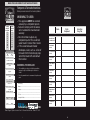
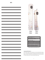
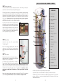
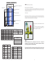
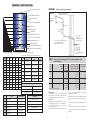
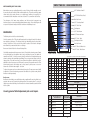
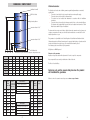
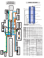
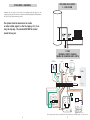
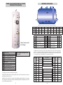
Tornado & Tempest Stainless™
Installation Guide
(including Solar & Horizontal)
Tel 01952 257963 Fax 01952 253452
Furrows Business Park, Haybridge Road
Wellington, Telford, Shropshire TF1 2FE
www.telford-group.com
Pbf.48994
March 2014
MAINS PRESSURE DOMESTIC HOT WATER APPLIANCE
Tempest & Tornado Stainless
Mains pressure domestic hot water cylinder
WARNING TO USER:
STORAGE
CAPACITY
IN LITRES
WEIGHT
WHEN FULL
IN KGS
90
125
150
170
200
250
300
400
500
125
165
195
220
250
310
360
448
557
Water Supply Pressure
Max
10 Bar
Min
1.5 Bar
Electric Immersion Heaters
14“/3kW • 230V AC
• This appliance MUST be serviced
annually by a competent person.
• Failure to comply with the above
will invalidate the manufacturer’s
warranty.
• Do not remove or adjust any
component part of this unvented
water heater: Contact the installer.
• If this unvented water heater
developes a fault, such as a flow of
hot water from the discharge pipe,
switch the heater off and contact
the installer.
Operating Pressure
WARNING TO INSTALLER:
3 BAR
Expansion Vessel Charge Pressure
See guide
Expansion Relief Valve Setting
6 BAR
• This installation is subject to building regulation
approval, notify Local Authority of intention to
install.
• Use only manufacturer’s recommended replacement
parts.
Date
Parts
Replaced
Installed and
Commissioned
First Annual
Service
Second Annual
Service
Third Annual
Service
Fourth Annual
Service
Fifth Annual
Service
Sixth Annual
Service
Pressure & Temperature
Relief Valve Setting
7 BAR / 90ºC
Installed by:
Maximum Primary Working Pressure
Name: ..................................................................................
2.5 BAR
Address: ..............................................................................
APPLIANCE SERIAL NO:
.............................................................................................
Tel. No.: ...............................................................................
Weight & Litres Capacity
Litres
Kgs
Direct
Completion Date: .................................................................
Seventh Annual
Service
Eighth Annual
Service
Ninth Annual
Service
Tenth Annual
Service
Indirect
Technical help line: 01952 257961
Telford Copper Cylinders Limited Unit 22 Furrows Business Park Telford TF1 2FE
1
26
Installers
Reg. No.
NOTES
3
6
3
6
2
2
5
5
1
4
1
2
Tempest
Stainless
Tornado
Stainless
1
2
3
4
5
6
4
2
Cold fill connection - 3/4” F *
Boiler flow and return connections - 3/4” F *
(Indirect version only)
Hot Water Draw Off - 3/4” F *
Immersion Heater - supplied loose (Two with direct versions)
Cylinder Thermostat pocket - 22mm (Indirect version only)
Pressure and temperature relief valve-fitted
* 400 litre cylinders and above are fitted using 1” BSP F.
Components supplied for fitting on site:
Inlet Control Group (comprising of a pressure reducing valve set to 3.0 bar, single check valve, filter and expansion
valve set to 6.0 bar). Cylinder thermostat (indirect models only) Energy cut out valve (indirect models only). Tundish
Expansion vessel (8 litre on 90 litre models, 12 litre on 125 & 150 litre models, 18 litre on 170 & 200 litre models, 24 litre
on 250 & 300 litre models, and 50 litre on 400 and 500 litre models) and Immersion heater(s).
25
2
PROBLEM Solving:
SYMPTOM
STEP 1
•
Read this instruction book carefully before proceeding. Tornado and Tempest Stainless™
cylinders are mains pressure products and are unvented. Unvented hot water systems
should only be fitted and serviced by competent persons, as defined by the current
edition of the Building Regulations (England and Wales) Approved Document G or
equivalent regulations.
•
The Tornado Stainless™ expansion vessel fits inside the top of the case. Tempest Stainless™
expansion vessel is fitted outside the case. Please verify which model you have
before proceeding with the installation.
No flow
Low Pressure
POSSIBLE
CAUSES
ACTION
Mains service valve not open
Open stop valve or replace.
Blocked filter.
Clean filter in base of Pressure
Reducing Valve.
Service valve not fully open or
partially blocked filter.
Ensure service valve is fully open or
clean filter in PRV.
Restricted delivery pipework
Replace damaged or
old pipework.
•
The unit must be stored in an upright and dry place before installation.
Low mains pressure.
Check incoming mains pressure or
discuss with local water supplier
•
Only use the components supplied with the Tornado and Tempest Stainless.™ Failure to do so
is potentially dangerous and will invalidate the product guarantee.
Expansion vessel.
Replenish or replace in accordance
with instructions in the maintenance
section.
•
The Tornado and Tempest Stainless™ should be connected to a public mains water
supply through the Inlet Control Group supplied. Indirect models must only be used with
pumped primary system.
Inlet Pressure Reducing Valve.
Replace PRV
Defective expansion relief valve or
debris or scale on seating of valve.
Operate expansion relief valve
mechanism to clear debris.
If discharge does not stop replace
expansion relief valve.
•
The standard Tornado and Tempest Stainless™ cannot be used with solid fuel boilers where
legislation applies.
•
Tornado and Tempest Stainless™ mains pressure systems require an annual safety check
by a competent person. Failure to carry out this safety check will invalidate the
warranty.
Discharge from
P&T or P valve(s)
Defective or incorrectly set cylinder
thermostat (ie temperature set too
high) allowing water to overheat.
Crossflow from uncontrolled cold
water mains supply to mixer tap or
shower valves.
STEP 2
Measure the area in which you plan to install the Tornado and Tempest Stainless™ and ensure that the floor
can support the weight of the cylinder when full.
Capacity
(litres)
Weight
When Full (Kgs)
90
125
Tornado
Stainless
Overall Height
(mm)
1220
Tempest
Stainless
Overall Height
(mm)
750
External
Diameter
(mm)
Heat Up Time
0 - 60°C
(mins)
Re-Heat Time to
60°C after 70%
Draw Off (mins)
510
26
18
125
165
150
195
1420
935
510
36
25
1540
1060
510
37
26
170
220
1780
1200
510
36
25
200
250
1600
1120
554
33
24
250
310
1920
1330
554
35
25
300
360
2080
1650
554
40
29
400
480
-
1590
660
46
34
500
580
-
1835
660
52
39
Check setting and operation of
cylinder thermostat (55-65oC).
Replace if necessary.
Check mixer taps and shower valve
and fit check valves or area
pressure controls if required.
Alternatively supply cold water to
mixer tap or shower valves from
balanced supply position on inlet
control set.
INDIRECT
Boiler not working. Pump and/or
control valve not operating.
Check boiler controls.
Check control functions and
replace faulty parts.
Cylinder thermostat upper limit stat
has operated.
Reset the button on the dual
cylinder thermostat after
investigating cause of overheating.
Not enough
hot water
Cylinder too small.
Check storage specification is
adequate. Telford Service
Department can help.
Water not
hot enough
Boiler not providing enough heat.
Cylinder thermostat settings
incorrect.
Adjust thermostat to between 55oC
and 65oC. Ensure boiler
thermostat is set to above 75oC.
Water fails to heat
Please note the above figures are for guideline purpose only.
DIRECT
Heat-up and re-heat times are for indirect models. All dimensions and weights are nominal.
Tornado and Tempest Stainless™ are designed to work efficiently under most water flow and pressure
conditions. However, the full potential of a mains pressure system is unlikely to be achieved if the flow falls
below 20 L/Min and the dynamic pressure is less than 1.5 bar. A minimum of 300mm clear space should be
left above the Tornado Stainless for maintenance.
3
Water fails to heat
Upper limit cut-out switch has
operated in immersion heater.
24
Turn off electricity supply, open
cap of I/H and reset cut-out
(red button) or press external reset
button if fitted.
DIMENSIONS - TEMPEST INDIRECT HI GAIN
Hot Water Draw Off
To prevent damage to the coil, cylinder and cylinder connections, make any soldered joints before
connecting pipework to the Tornado and Tempest Stainless.™
T&P Relief Valve
STEP 3
Position the unit vertically and make the incoming cold water connection to the fitting labelled
“mains water inlet”.
For commissioning and later maintenance purposes it is essential to fit
a service valve immediately before the connection to the Inlet Control
Group.
Secondary Return
Boiler
Aquastat Pocket
Immersion Heater 1 3/4”
E
D
C
B
A
Installing the Inlet Control Group
The mains cold water supply should first pass through the pressure
reducing valve, which reduces the pressure to 3.0 bar - this is factory
set and cannot be adjusted - and then through the 6.0 bar expansion
valve . The Inlet Control Group includes a single check valve and filter.
*NB Upon commissioning. The expansion vessel pressure, should
be adjusted to 0.2 bar less than the incoming water pressure. The
vessel needs to be installed in a secure fashion.
Cold Water Inlet
F
90
125
150
170
200
250
300
400
500
Height
750
935
1060
1200
1120
1330
1650
1590
1835
Diameter
510
510
510
510
554
554
554
660
660
A
170
170
170
170
195
195
195
240
240
B
200
200
200
200
225
225
225
270
270
C
400
400
400
450
475
555
555
640
640
D
495
495
495
600
625
845
845
870
890
E
-
-
-
-
815
975
1255
1240
1390
F
550
750
880
1030
930
1140
1435
1340
1590
Ensure that the Inlet Control Group is fitted adjacent to the cylinder with the arrows on the side
pointing in the direction of the flow. It must be no further away than 500mm from the cylinder and
have no devices or connections/draw offs between it and the cylinder*. Balanced supplies for
showers and mixer taps only should be taken from the appropriate connection on the Inlet Control
Group(see illustration). Water regulations require that a single check valve should be fitted in the
balanced draw off to prevent back flow. The inlet group supplied incorporates a single check
within the body of the group.
*The expansion vessel for the Tempest Stainless™ must be fitted between the inlet control group
and the unit (see illustration)
•
Time to
Cap (L) Time to
re-heat from
re-heat
from Cold 75% draw-off
with Boiler
90 Ltr
13 Min
9 Min
125 Ltr
19 Min
13 Min
150 Ltr
19 Min
13 Min
19 Min
Inlet group with expansion vessel
position (Tempest only) also shows
drain off position and balanced
supply.
All dimensions are given in mm and are subject to change without notice.
Cap (Ltr)
170 Ltr
(all cylinders)
13 Min
200 Ltr
17 Min
12 Min
250 Ltr
18 Min
13 Min
300 Ltr
20 Min
15 Min
400 Ltr
23 Min
18 Min
500 Ltr
25 Min
20 Min
Foam Information
ODP Ozone Depletion potential = 0
GWP Global Warning Potential = 2.2
Foam Type = Polyurethane
British Standard 1566, D: 2002
Cap (L) 24 Hrs
Standing
Heat Loss
90 Ltr
1.21Kw/24Hrs
125 Ltr 1.33Kw/24Hrs
150 Ltr 1.50Kw/24Hrs
Parts Supplied
Dual High Limit Stat
3Kw Immersion Heater 240V single Phase
Expansion Vessel
Temperature & Pressure Relief
3Bar Inlet Control Group
2 Port Motorised Valve
23
170 Ltr 1.62Kw/24Hrs
200 Ltr 1.75Kw/24Hrs
250 Ltr 2.10Kw/24Hrs
300 Ltr 2.30Kw/24Hrs
400 Ltr 2.94Kw/24Hrs
500 Ltr 3.15Kw/24Hrs
Immersion
Heater
A suitable means for draining the unit must be incorporated into the cold feed
(see illustration) - Positioning the drain as suggested will allow a minimum of 80% of the
cylinder to be drained off.
STEP 4 (all cylinders)
1 x 3Kw 240v
single phase
1 x 3Kw 240v
single phase
1 x 3Kw 240v
single phase
1 x 3Kw 240v
single phase
1 x 3Kw 240v
single phase
1 x 3Kw 240v
single phase
1 x 3Kw 240v
single phase
1 x 3Kw 240v
single phase
1 x 3Kw 240v
single phase
Connect the discharge pipework and tundish to the valve labelled “P&T” The tundish should be
connected to the cylinder using 15mm metal pipe.
The tundish (supplied) must be fitted within 600mm of the outlet of the P&T valve and have at
least 300mm of straight metal pipe below it, before any elbow or bend.
The pipework below the tundish should be fitted in accordance with the current edition of the
Building Regulations (see page 7).
The discharge from the expansion valve on the Inlet Control Group must be connected into the
discharge pipe work.
We recommend a double check valve should be fitted to the hot water draw off to prevent any back
pressure.
4
EASYFIT KIT FOR TELFORD TORNADO CYLINDERS
STEP 5 (indirect cylinders only)
Connect the boiler flow and return to the labelled connections. Before making the connections
ensure that the coil is free from obstructions by blowing through it.
1
The Energy Cut Out valve is an essential part of the safety requirements for indirect mains
pressure cylinders and should be installed on the primary flow to the cylinder with port ‘B’
(embossed on side of valve body) to the cylinder. The valve will open and close on receiving a
signal from the cylinder thermostat. No further control is required for the hot water in a two zone
valve system. This valve must also be used in a flow share (Y Plan) system, in conjunction
with the mid-position valve, to act as a safety cut out valve.
2
DIAGRAM KEY
3
X1
X1 - Mains water feed
X2
X3
X3 - Heating expansion vessel
connection
X4
4
The cylinder thermostat controls the temperature of the hot
water and also acts as an emergency cut out in the event that
the boiler temperature controls fail. The cylinder thermostat
is fitted into the pocket labelled “Store Temp Control” in the
cylinder, and should be connected to operate the energy cut
out valve in accordance with the wiring diagram for the
scheme being installed (see pages 11 and 12).
X2 - Balanced supply
X4 - Flow from boiler
X5 - Return to boiler
6
X6 - Return from coil
5
X7 - Flow to coil
7
X5
X8 - Discharge to outside (D2)
1 - Inlet Group
2 - Filling loop
STEP 6 (all cylinders)
X6
Connect hot water draw off to connection labelled
“Hot Water Draw Off”.
3 - Isolating valve to heating
X8
12
NB: If the secondary circulation system (where used)
contains more than 15 litres of water a separate expansion
vessel must be provided to compensate for the larger stored
volume.
4 - Isolating valve
5 - T&P Relief
RETURN
9
6 - Pump
8
7 - By-pass
STEP 7 (all cylinders)
8 - Cylinder aquastat
Make electrical connections to the immersion heaters - see
wiring diagram inside cap of immersion heater. All electrical
installations must be to IEEE standards.
10
9 - Heating 2 port valve
FLOW
The immersion heaters supplied with the Tornado and
Tempest Stainless™ cylinder are of a special construction and
include both a control thermostat and overheat protection. When fitting, ensure the ‘O’ ring is
positioned correctly on the head of the immersion heater and lubricate before fitting. Fit it by hand
until almost home then tighten gently as the ‘O’ rings will seal easily. Only use genuine
replacement parts which can be obtained from a Telford Copper Cylinders approved
merchant.
10 - Hot water 2 port valve
11 - Drain off point
X7
12 - Coil by-pass regulator valve
11
DO NOT use the pipework as a carrying aid when positioning this cylinder.
Separate power supplies must be made available for the pump, two port valves and the aquastat.
Ensure that the immersion heater control setting is set between 55°C and 65°C for economical
operation. The upper limit thermostat is set to 80oC and must not be tampered with.
5
Installation must be carried out as described in this installation guide with reference to this section where
appropriate. This will ensure compliance with Building Regulations, IEEE Regulations and Telford Copper
Cylinders warranty provisions.
22
DIMENSIONS - TORNADO DIRECT
STEP 8 Commissioning & Operating
Expansion Vessel Supplied Loose
Ensure all connections are fully tightened.
T&P Relief Valve
Hot Water Draw Off
Open all of the hot taps supplied by the cylinder and slowly fill the unit by opening the service valve.
Continue to fill the unit until water runs continuously from all of the open taps. Open the service
valve fully, and close all hot taps.
Secondary Return*
Check for leaks.
Immersion Heater 1 3/4”
Heat the water to 60oC. When up to temperature, the cylinder should be isolated and drained to
flush out any flux/solder introduced during the installation process. The filter in the inlet control
set should be removed, cleaned and re-fitted - see photograph.
Immersion Heater 1 3/4”
Cold Water Inlet
Reheat the cylinder to desired temperature and recheck
for leaks.
For safety and energy saving reasons it is advisable to
operate the Tempest Tornado Stainless™ at a
temperature between 55°C and 60°C.
E DCBA
All dimensions are given in mm and are subject to change without notice
Cap (Ltr)
90
125
150
170
200
250
300
Height
1220
1420
1540
1780
1600
1920
2080
Dia
510
510
510
510
554
554
554
A
170
170
170
170
195
195
195
B
200
200
200
200
225
225
225
C
495
495
495
600
625
845
845
D
-
-
-
-
815
975
1255
E
550
750
880
1030
930
1140
1435
Parts Supplied
3Kw Immersion Heater 240V single Phase
Temperature & Pressure Relief
Expansion Vessel
3Bar Inlet Control Group
Foam Information
ODP Ozone Depletion Potential = 0
GWP Global Warning Potential = 2.2
Foam Type = Polyurethane
British Standard 1566,D:2002
Cap (L) 24Hrs Standing
Heat Loss
90Ltr
1.21Kw/24Hrs
125Ltr
1.33Kw/24Hrs
150Ltr
1.50Kw/24Hrs
170Ltr
1.62Kw/24Hrs
200Ltr
1.75Kw/24Hrs
250Ltr
2.10Kw/24Hrs
300Ltr
2.30Kw/24Hrs
STEP 9
Place this instruction book in a convenient place for the end user. Complete the
Benchmark Log Book and leave with the cylinder. Complete the guarantee card and post
to Telford Copper Cylinders to validate the warranty.
Immersion
Heater
1 x 3Kw 240v
single phase
1 x 3Kw 240v
single phase
1 x 3Kw 240v
single phase
1 x 3Kw 240v
single phase
1 x 3Kw 240v
single phase
1 x 3Kw 240v
single phase
1 x 3Kw 240v
single phase
21
Cap
(L)
Time to re-heat from cold
Time to Re-heat from 75%
Draw-off with Boiler
90Ltr
52 Min
27 Min
125Ltr
72 Min
37 Min
150Ltr
86 Min
45 Min
170Ltr
98Min
51 Min
200Ltr
108 Min
63 Min
250Ltr
144 Min
75 Min
300Ltr
202 Min
136 Min
We recommend the installation of a 22mm gate valve between the flow connection on the
cylinder and the return connection on the cylinder as illustrated in image in step 6 page 5.
6
DIMENSIONS - TORNADO INDIRECT
Discharge - Building Regulations:
Expansion Vessel Supplied Loose
Discharge pipes must be installed in accordance with the latest edition of the Building Regulations.
T&P Relief Valve
Discharge Pipes
The discharge pipe (D1) from the vessel up to and including the tundish is generally supplied by
the manufacturer of the hot water storage system (see paragraph 3.5). Where otherwise, the
installation should include the discharge pipe(s) (D1) from the safety device(s). In either case the
tundish should be vertical, located in the same space as the unvented hot water storage system
and be fitted as close as possible and within 600mm of the safety device e.g. the temperature relief
valve.
The discharge pipe (D2) from the tundish should terminate in a safe place where there is no risk
to persons in the vicinity of the discharge, be of metal and:
a. be at least one pipe size larger than the normal outlet size of the safety device unless its total
equivalent hydraulic resistance exceeds that of a straight pipe 9m long i.e. discharge pipes
between 9m and 18m equivalent resistance length should be at least two sizes larger than the
nominal outlet size of the safety device, between 18 and 27m at least 3 sizes larger, and so
on. Bends must be taken into account in calculating the flow resistance. Refer to Diagram 1,
Table 1 and the worked example. An alternative approach for sizing discharge pipes would be
to follow BS 6700: 1987 Specification for design installation, testing and maintenance of
services supplying water for domestic use within buildings and their curtilages, Appendix E,
section E2 and table 21.
b. have a vertical section of pipe at least 300mm long, below the tundish before any elbows or
bends in the pipework.
c. be installed with a continuous fall.
d. have discharges visible at both the tundish and the final point of discharge but where this is
not possible or is practically difficult there should be clear visibility at one or other of these
locations. Examples of acceptable discharge arrangements are:
i. ideally below a fixed grating and above the water seal in a trapped gully.
ii. downward discharges at low level; i.e. up to 100mm above external surfaces such as car parks,
hard standings, grassed areas etc. are acceptable providing that where children may play or
otherwise come into contact with discharges a wire cage or similar guard is positioned to
prevent contact, whilst maintaining visibility.
iii. discharges at high level; e.g. into a metal hopper and metal down pipe with the end of the
discharge pipe clearly visible (tundish visible or not) or onto a roof capable of withstanding high
temperature discharges of water and 3 m from any plastics guttering system that would
collect such discharges (tundish visible).
iv. where a single pipe serves a number of discharges, such as in blocks of flats, the number
served should be limited to not more than 6 systems so that any installation discharging can
be traced reasonably easily. The single common discharge pipe should be at least one pipe
size larger than the largest individual discharge pipe (D2) to be connected. If unvented hot
water storage systems are installed where discharges from safety devices may not beapparent
i.e. in dwellings occupied by blind, infirm or disabled people, consideration should be given to
the installation of an electronically operated device to warn when discharge takes place.
Note:
The discharge will consist of scalding water and steam. Asphalt, roofing felt and non-metallic
rainwater goods may be damaged by such discharges.
7
Hot Water Draw Off
Secondary Return
Boiler
Aquastat Pocket
Immersion Heater 1 3/4”
Boiler
Cold Water Inlet
F E DCBA
All dimensions are given in mm and are subject to change without notice
Cap (Ltr)
90
125
150
170
200
250
300
Height
1220
1420
1540
1780
1600
1920
2080
Dia
510
510
510
510
554
554
554
A
170
170
170
170
195
195
195
B
200
200
200
200
225
225
225
555
C
400
400
400
450
475
555
D
495
495
495
600
625
845
845
E
-
-
-
-
815
975
1255
F
550
750
880
1030
930
1140
1435
Parts Supplied
Dual High Limit Stat
Temperature & Pressure Relief
3Kw Immersion Heater 240V single Phase
3Bar Inlet Control Group
Expansion Vessel
2 Port Motorised Valve
Foam Information
ODP Ozone Depletion Potential = 0
GWP Global Warning Potential = 2.2
Foam Type = Polyurethane
British Standard 1566,D:2002
Cap (L) 24Hrs Standing
Heat Loss
90 Ltr
1.21Kw/24Hrs
125 Ltr
1.33Kw/24Hrs
150 Ltr
1.50Kw/24Hrs
170 Ltr
1.62Kw/24Hrs
200 Ltr
1.75Kw/24Hrs
250 Ltr
2.10Kw/24Hrs
300 Ltr
2.30Kw/24Hrs
Immersion
Heater
1 x 3Kw 240v
single phase
1 x 3Kw 240v
single phase
1 x 3Kw 240v
single phase
1 x 3Kw 240v
single phase
1 x 3Kw 240v
single phase
1 x 3Kw 240v
single phase
1 x 3Kw 240v
single phase
20
Cap
(L)
Time to re-heat from cold
Time to Re-heat from 75%
Draw-off with Boiler
90 Ltr
26 Min
18 Min
125 Ltr
36 Min
25 Min
150 Ltr
37 Min
26 Min
170 Ltr
36 Min
25 Min
200 Ltr
33 Min
24 Min
250 Ltr
35 Min
25 Min
300 Ltr
40 Min
29 Min
DIMENSIONS - TEMPEST TRIPLE COIL
3/4” F Hot Water Draw Off
T&P Relief Valve (Fitted)
Plain Solar Sensor
3/4” F Secondary Return*
3/4” F
DIAGRAM 1
See para 3.9
- Typical discharge pipe arrangement
metal discharge pipe (D1) from
temperature relief valve to tundish
safety device
(e.g. temperature
relief valve)
tundish
28mm
Boiler Flow
Plain Aquastat
Boiler Return
3/4” F
28mm
300mm
minimum
Immersion Heater 1 3/4”
3/4” F Solar / Boiler Flow
Plain Aquastat Pocket
Discharge below
fixed grating
(3.9d gives alternative
points of discharge)
metal discharge pipe (D2) from tundish,
with continuous fall. See 3.9d i-iv,
Table 1 and worked example
Plain Solar Sensor
3/4” F 3Bar Cold Water Inlet
3/4” F Solar / Boiler Return
All dimensions are given in mm for guidance only
J I HG F E DCBA
trapped gully
* Cylinders 400 Ltrs and above are fitted with 1” BSPF Tappings
Cap (Ltr)
200
250
300
400
500
Cap (L)
24Hrs Standing
Heat Loss
Immersion
Heater
Boiler & Solar
Cap (L)
Height
1120
1330
1650
1590
1835
170 Ltr
1.62Kw/24Hrs
3Kw 240v Single Phase
Dia
554
554
554
660
660
A
190
190
190
235
235
200 Ltr
1.75Kw/24Hrs
3Kw 240v Single Phase
B
245
245
245
285
285
250 Ltr
2.10Kw/24Hrs
3Kw 240v Single Phase
C
390
390
390
435
435
D
500
500
500
620
620
300 Ltr
2.30Kw/24Hrs
3Kw 240v Single Phase
E
545
575
570
715
715
400 Ltr
2.94Kw/24Hrs
3Kw 240v Single Phase
F
585
640
640
820
820
G
780
890
885
1120
1120
500 Ltr
3.15Kw/24Hrs
3Kw 240v Single Phase
50% Solar
50% Boiler
50% Solar
50% Boiler
50% Solar
50% Boiler
50% Solar
50% Boiler
50% Solar
50% Boiler
50% Solar
50% Boiler
H
890
1025
1250
1240
1260
I
890
1025
1020
1240
1390
J
Cap
(L)
930
1140
1430
1340
Time to Re-heat from 75% Draw-off
with Solar
Parts Supplied
Table 1
- Sizing of copper discharge pipe ‘D2’ for common temperature relief
valve outlet sizes
Valve
Outlet
Size
Minimum Size
of Discharge
pipe D1*
Minimum Size
of Discharge
Pipe D2*
from tundish
Maximum resistance allowed,
expressed as a length of straight
pipe (i.e. no elbows or bends)
Resistance created by
each elbow or bend
G1/2
15mm
G3/4
22mm
G1
28mm
22mm
28mm
35mm
28mm
35mm
42mm
35mm
42mm
54mm
up to 9m
up to 18m
up to 27m
up to 9m
up to 18m
up to 27m
up to 9m
up to 18m
up to 27m
0.8m
1.0m
1.4m
1.0m
1.4m
1.7m
1.4m
1.7m
2.3m
2 x Dual High Limit Stat
Temperature & Pressure Relief
3Kw Immersion Heater 240V single Phase
3Bar Inlet Control Group
*see 3.5, 3.9, 3.9(a) and Diagram 1
Expansion Vessel
2 Port Motorised Valve
Worked Example:The example below is for a G1/2 temperature relief valve
with a discharge pipe (D2) having 4 no. elbows and length
of 7m from the tundish to the point of discharge.
From Table 1:
Maximum resistance allowed for a straight length of 22mm
copper discharge pipe (D2) from a G1/2 temperature relief
valve is: 9.0m. Subtract the resistance for 4 No. 22mm
elbows at 0.8m each = 3.2m
Therefore the maximum permitted length equates to: 5.8m.
1590
Time to Re-heat from 75%
Draw-off with Boiler
Foam Information
170 Ltr Dependent on UV
85Ltr = 18Min
ODP Ozone Depletion Potential = 0
200 Ltr Dependent on UV
100Ltr = 20Min
GWP Global Warning Potential = 2.2
250 Ltr Dependent on UV
125Ltr = 25Min
Foam Type = Polyurethane
300 Ltr Dependent on UV
150Ltr = 26Min
British Standard 1566,D:2002
400 Ltr Dependent on UV
200Ltr = 24Min
500 Ltr Dependent on UV
250Ltr = 25Min
19
5.8m is less than the actual length of 7m therefore
calculate the next largest size.
Maximum resistance allowed for a straight length of 28mm
pipe (D2) from G1/2 temperature relief valve equates to:
18m.
Subtract the resistance for 4 No. 28mm elbows at 1.0m each
= 4m.
Therefore the maximum permitted length equates to 14m.
As the actual length is 7m, a 28mm (D2) copper pipe will be
satisfactory.
8
TEMPEST TWIN COIL / SOLAR INFORMATION DATA
NOTES ON WATER QUALITY AND SCALING:
Water hardness can vary considerably around the country. If furring of kettles normally occurs in
the area, then the unit should be fed with conditioned water only. This can be provided by a water
softener with a high capacity flow rate, or a suitable water conditioner (not supplied). It is
recommended that the temperature controls are set below 650C to prevent lime scale build up.
3/4” F Hot Water Draw Off
The performance of all water storage appliances and their associated components may
deteriorate if you do not protect adequately against hard water scaling. If more than 150ppm salts
are present in local water samples, an effective conditioner should always be used.
Plain Solar Sensor
1/2” T&P Relief Valve (Fitted)
3/4” F Secondary Return*
3/4” F Boiler Flow
Plain Aquastat
3/4” F Boiler Return
MAINTENANCE:
1 3/4” Immersion Heater
The following checks should be conducted annually:
3/4” F Solar / Boiler
Plain Aquastat Pocket
Check the operation of the T & P valve and Expansion valve by rotating the heads of the valves in
turn until water is discharged. The discharge should stop immediately when the valve head is
released. Should this not be the case the valve should be replaced. Check that the discharged
water flows freely to waste and that there is no blockage.
Plain Solar Sensor
3/4” F 3Bar Cold Water Inlet
Remove and clean the filter in the Pressure Reducing Valve.
Check that the expansion vessel charge pressure is set at 0.2 bar below the incoming pressure. If water
is being discharged from the expansion valve it may be indicative of pressure loss within the
expansion vessel itself. To check the pressure, isolate the unit from the cold supply and release any
pressure by opening a hot tap until water stops flowing. Then use a tyre pressure gauge to verify the
charge pressure. If the unit is more than 5 years old when this problem is experienced it may be
advisable to replace the pressure vessel. If however, the pressure in the expansion vessel is 0.2 bar
below incoming pressure the discharge may be being caused by back pressure or cross-over
between the cold and hot water supplies - see below.
To replace the pressure vessel, unscrew from threaded connection. The new pressure vessel should
be adjusted to 0.2 bar below incoming pressure and then fitted to the cylinder, ensuring that the
threads are sealed appropriately.
Back pressure
Back pressure from a faulty or uncontrolled mixer valve or appliance will cause the cylinder to over
pressurise and may result in water being discharged from the expansion valves. To protect the
cylinder we recommend the fitting of a check valve on the hot water draw off to prevent back flow
into the cylinder.
3/4” F Solar / Boiler Return
J I HG F EDCBA
All dimensions are given in mm
* Cylinders 400 Ltrs and above are fitted with 1” BSPF Tappings
Cap (Ltr) 170
200
250
300
400
500
Cap (L)
24Hrs Standing
Heat Loss
Immersion
Heater
170Ltr
1.62Kw/24Hrs
3Kw 240v Single Phase
200Ltr
1.75Kw/24Hrs
3Kw 240v Single Phase
Height
1200
1120
1330
1650
1590
1835
Dia
510
554
554
554
660
660
A
175
190
190
190
235
235
B
175
245
245
245
285
285
250Ltr
2.10Kw/24Hrs
3Kw 240v Single Phase
50% Solar
50% Boiler
50% Solar
50% Boiler
50% Solar
50% Boiler
50% Solar
50% Boiler
50% Solar
50% Boiler
50% Solar
50% Boiler
C
395
390
390
390
435
435
300Ltr
2.30Kw/24Hrs
3Kw 240v Single Phase
D
500
500
500
500
620
620
400Ltr
2.94Kw/24Hrs
3Kw 240v Single Phase
E
535
545
575
570
715
715
F
585
585
640
640
820
820
500Ltr
3.15Kw/24Hrs
3Kw 240v Single Phase
G
865
780
890
885
1120
1120
H
N/A
890
1025
1250
1240
1390
I
1015
890
1025
1020
1240
1260
Dual High Limit Stat
Temperature & Pressure Relief
J
1040
930
1140
1430
1340
1590
3Kw Immersion Heater 240V single Phase
3Bar Inlet Control Group
Expansion Vessel
2 Port Motorised Valve
Parts Supplied
Use only genuine Telford replacement parts on all repairs.
Cap
(L)
170Ltr
9
Boiler & Solar
Cap (L)
Time to Re-heat from 75%
Draw-off with Solar
Dependent on UV
Time to Re-heat from
75% Draw-Off with Boiler
Foam Information
85 Ltr = 18 Min
ODP Ozone Depletion Potential = 0
200Ltr
Dependent on UV
100 Ltr = 20 Min
GWP Global Warning Potential = 2.2
250Ltr
Dependent on UV
125 Ltr = 25 Min
Foam Type = Polyurethane
British Standard 1566,D:2002
300Ltr
Dependent on UV
150 Ltr = 26 Min
400Ltr
Dependent on UV
200 Ltr = 24 Min
500Ltr
Dependent on UV
250 Ltr = 25 Min
18
DIMENSIONS - TEMPEST DIRECT
Lifetime Guarantee:
Hot Water Draw Off
T&P Relief Valve
The Stainless steel vessel carries a lifetime guarantee against faulty manufacture or materials,
provided that:
The product is used solely for the storage of water from a mains public supply.
The product has not been modified or tampered with.
The product has been installed and maintained in accordance with the installation
instructions.
The product has not been subjected to damage caused by frost, or other external influence.
The Guarantee Card, supplied with the product, has been completed and returned to Telford
Water Heaters within 28 days of installation.
l
l
l
Secondary Return
l
Immersion Heater 1 3/4”
The immersion heater, water control valves, cylinder thermostat, expansion vessel and energy cut
out valves are guaranteed for two years from the date of manufacture on a new build. For new
install/replacement one year.
This guarantee is only available in the United Kingdom of Great Britain and Northern Ireland.
Immersion Heater 1 3/4”
Claims made against our Lifetime Guarantee must be supported with evidence of purchase and the
product serial number, along with a copy of the completed Benchmark Log Book.
Your Statutory rights are not affected by this guarantee.
All cylinders are WRAS Approved.
Cold Water Inlet
E
D
C
B
A
All dimensions are given in mm and are subject to change without notice.
Cap (Ltr)
90
125
150
170
200
250
300
400
500
Height
750
935
1060
1200
1120
1330
1650
1590
1835
Diameter
510
510
510
510
554
554
554
660
660
A
170
170
170
170
195
195
195
240
240
B
200
200
200
200
225
225
225
270
270
C
410
410
620
620
645
645
645
690
690
D
-
-
-
-
815
975
1255
1240
1390
E
550
750
880
1030
930
1140
1435
1340
1590
Exclusions to the guarantee
Any labour charges associated with replacement of the unit or any of its components.
Any consequential losses caused by malfunction or failure of the unit.
The effects of scale build up.
Failure to carry out the annual safety check on this product
will invalidate the guarantee.
Failure to service the expansion vessel may cause a serious escape of water.
Time to
Cap (L) Time to
re-heat from
re-heat
from Cold 75% draw-off
with Boiler
Foam Information
ODP Ozone Depletion potential = 0
GWP Global Warning Potential = 2.2
Foam Type = Polyurethane
British Standard 1566, D: 2002
Cap (L) 24 Hrs
Standing
Heat Loss
90 Ltr
1.21Kw/24Hrs
90 Ltr
52 Min
27 Min
125 Ltr
72 Min
37 Min
125 Ltr 1.33Kw/24Hrs
150 Ltr
86 Min
45 Min
150 Ltr 1.50Kw/24Hrs
170 Ltr
98 Min
51 Min
170 Ltr 1.62Kw/24Hrs
200 Ltr
108 Min
63 Min
250 Ltr
144 Min
75 Min
200 Ltr 1.75Kw/24Hrs
Parts Supplied
300 Ltr
202 Min
136 Min
400 Ltr
242 Min
198 Min
500 Ltr
289 Min
236 Min
250 Ltr 2.10Kw/24Hrs
2 x 3Kw Immersion Heater 240V single Phase
Expansion Vessel
Temperature & Pressure Relief
3Bar Inlet Control Group
17
300 Ltr 2.30Kw/24Hrs
400 Ltr 2.94Kw/24Hrs
500 Ltr 3.15Kw/24Hrs
Immersion
Heater
2 x 3Kw 240v
single phase
2 x 3Kw 240v
single phase
2 x 3Kw 240v
single phase
2 x 3Kw 240v
single phase
2 x 3Kw 240v
single phase
2 x 3Kw 240v
single phase
2 x 3Kw 240v
single phase
2 x 3Kw 240v
single phase
2 x 3Kw 240v
single phase
10
S-PLAN WIRING LAYOUT
AND SYSTEMS SCHEMATIC
DIMENSIONS - TEMPEST INDIRECT
L NE
CH valve
Danfos
T&P Relief Valve
Secondary Return
Boiler
HW valve
Danfos
SW Live
2core + E
0.75mm2
Grundfos
Pump
Boiler
Hot Water Draw Off
Aquastat Pocket
Telford Stat
C 2 1
Cold Water Inlet
F
E
D
C
B
A
All dimensions are given in mm and are subject to change without notice.
Cap (Ltr)
90
125
150
170
200
250
300
400
500
Height
750
935
1060
1200
1120
1330
1650
1590
1835
Diameter
510
510
510
510
554
554
554
660
660
A
170
170
170
170
195
195
195
240
240
B
200
200
200
200
225
225
225
270
270
C
400
400
400
450
475
555
555
640
640
D
495
495
495
600
625
845
845
870
890
E
-
-
-
-
815
975
1255
1240
1390
F
550
750
880
1030
930
1140
1435
1340
1590
C 2
LIVE AND EARTH ONLY
2 core + E
0.75mm2
E
Boiler
Time to
Cap (L) Time to
re-heat from
re-heat
from Cold 75% draw-off
Danfoss Room
Thermostat
(not prewired)
1 2 4
3 Core
0.75mm2
with Boiler
DRAWING SHOWS
“S” PLAN SYSTEM WITH DANFOSS CONTROLS
FAILURE TO INSTALL WILL INVALIDATE GUARANTEE
Regulating
Stat
Dual Control Stat
2
1
NOTE
THE CONTROLS PROVIDED MUST BE USED
2 core + E
0.75mm2
ONE IMMERSION HEATER REQUIRES A 16 AMP SUPPLY
TWO IMMERSION HEATERS REQUIRE TWO 16 AMP SUPPLIES
11
High Limit
Stat
4
3
E
LNE
230v/3
amp/50hz
DO NOT USE
NEUTRAL
9 10
5
6
7
N L Hw HG
ON ON
8
Programmer
4 core
0.75mm2
Immersion Heater 1 3/4”
90 Ltr
26 Min
18 Min
125 Ltr
36 Min
25 Min
150 Ltr
37 Min
26 Min
170 Ltr
36 Min
25 Min
200 Ltr
33 Min
24 Min
250 Ltr
35 Min
25 Min
300 Ltr
40 Min
29 Min
400 Ltr
45 Min
35 Min
500 Ltr
50 Min
40 Min
Foam Information
ODP Ozone Depletion potential = 0
GWP Global Warning Potential = 2.2
Foam Type = Polyurethane
British Standard 1566, D: 2002
Cap (L) 24 Hrs
Standing
Heat Loss
90 Ltr
1.21Kw/24Hrs
125 Ltr 1.33Kw/24Hrs
150 Ltr 1.50Kw/24Hrs
Parts Supplied
Dual High Limit Stat
3Kw Immersion Heater 240V single Phase
170 Ltr 1.62Kw/24Hrs
200 Ltr 1.75Kw/24Hrs
250 Ltr 2.10Kw/24Hrs
Expansion Vessel
Temperature & Pressure Relief
3Bar Inlet Control Group
2 Port Motorised Valve
16
300 Ltr 2.30Kw/24Hrs
400 Ltr 2.94Kw/24Hrs
500 Ltr 3.15Kw/24Hrs
Immersion
Heater
1 x 3Kw 240v
single phase
1 x 3Kw 240v
single phase
1 x 3Kw 240v
single phase
1 x 3Kw 240v
single phase
1 x 3Kw 240v
single phase
1 x 3Kw 240v
single phase
1 x 3Kw 240v
single phase
1 x 3Kw 240v
single phase
1 x 3Kw 240v
single phase
PIPE WORK LOGIC LAYOUTS
S - PLAN SYSTEM
FITTING NOTES - HORIZONTAL
Installation must be carried out as described in this installation guide with reference to this
section where appropriate. This will ensure compliance with Building Regulations, IEEE Regulations
and Telford Copper Cylinders warranty provisions.
The cylinder should be mounted on the cradles
(or other suitable support) so that the tappings A, B, C are
along the top edge. The cylinder MUST NOT be rotated
around the long axis.
Y PLAN
TORNADO & TEMPEST STAINLESS
(WIRING FOR FLOWSHARE ONLY V4073H
3 Amp
Switched Fuse Spur
Flow Share Valve
V4073H
Room Stat
Fused
Neutral
No 2
L
N
E
Boiler
White
Orange
Loop 1 & 10
SL
Grey
Pump
1
2
3
4
5
6
7
8
9
10
11
12
Wiring Centre
Grey
Brown
Orange
No 3
Programmer
L N E
HW
OFF
HW
ON
HTG
ON
High
Limit
C 2
Regulating
Stat
E
Neutral
No 2
C 21
Dual Stat
Telford 2 Port Valve
Telford Copper Cylinders hold no responsibility for the wiring diagram above. The wiring diagram is for Guide line only
15
12
TELFORD SOLAR UNVENTED TWIN COIL CYLINDER
STANDARD TAPPING DIAGRAM
HORIZONTAL INSTALLATION
B
A
D
C
E
J
All dimensions are given in mm and are subject to change without notice.
D
F
G
I
Cap (Ltr)
90*
125
150
170
200
250
300
400
500
Length
750
935
1060
1200
1120
1330
1650
1590
1835
Diameter
510
510
510
510
550
550
550
660
660
Height
610
610
610
610
650
650
650
760
760
Key
A
A
H
J
* Cylinders 400 Ltr and above are fitted
with 1” BSPF Tappings
Description
Hot Water Draw Off 3/4 “F
Position of tappings may differ slightly according to
cylinder capacity.
Solar Sensor Pockets
Hot Water Draw Off- 3/4” F
Pressure & Temperature relief valve - fitted
Boiler flow & return connections - 3/4” F
Cylinder thermostat pocket - 22mm
Immersion heater
Solar coil flow connection - 3/4” F
Solar coil return connection - 3/4” F
Auxiliary cylinder thermostat pocket - 22mm
Cold fill connection - 3/4” F
Dir
Key
Y
Y
F
Description
Immersion Heater 1 3/4 “ Direct Only
Dir
N
Y
B
T&P Relief Valve (Fitted)
Y
Y
G
Aquastat Pocket Indirect only
Y
N
Boiler Flow 3/4 “F Indirect only
Y
N
H
Boiler Return“ 3/4 “F Indirect only
Y
N
D
Secondary Return 3/4 “F (200, 250, 300 only)
Y
Y
I
Cold Feed 3/4 “F (With Dip Pipe)
Y
Y
E
Immersion Heater 1 3/4 “ Indirect and Direct
Y
Y
J
1
Y
Y
Un-Vented Components Supplied
/2 “ BSP Tapping for drain point
Expansion vessel (supplied loose)
• Installation must be carried out as described in this guide with reference to this section where appropriate.
This will ensure compliance with Building Regulations, IEEE Regulations and Telford Copper Cylinders warranty
provisions. • The cylinder should be mounted on the cradles (or other suitable support) so that the connections A, B,
I, (C) are along the top edge. The cylinder MUST not be rotated around the long axis.
Time to
Cap (L) Time to
re-heat from
re-heat
from Cold 75% draw-off
with Boiler
90 Ltr
26 Min
18 Min
125 Ltr
36 Min
25 Min
150 Ltr
37 Min
26 Min
170 Ltr
36 Min
25 Min
The following components are supplied with the cylinder:-
200 Ltr
33 Min
24 Min
T&P Relief Valve (fitted), Immersion Heater, Aquastat, Safety Cut Out Valve, High Pressure Inlet Group
and Expansion Vessel (sized to suit).
250 Ltr
35 Min
25 Min
300 Ltr
40 Min
29 Min
Installation must be carried out as described in this installation guide with reference to this section
where appropriate. This will ensure compliance with Building Regulations, IEEE Regulations and Telford
Copper Cylinders warranty provisions.
400 Ltr
45 Min
35 Min
500 Ltr
50 Min
40 Min
Foam Information
ODP Ozone Depletion potential = 0
GWP Global Warning Potential = 2.2
Foam Type = Polyurethane
British Standard 1566, D: 2002
Cap (L) 24 Hrs
Standing
Heat Loss
90 Ltr
1.21Kw/24Hrs
125 Ltr 1.33Kw/24Hrs
150 Ltr 1.50Kw/24Hrs
Parts Supplied
13
Ind
C
* 90 litre available as direct only.
A
B
C
D
E
F
G
H
I
J
Ind
170 Ltr 1.62Kw/24Hrs
Dual High Limit Stat
3Kw Immersion Heater 240V single Phase
Expansion Vessel
Temperature & Pressure Relief
3Bar Inlet Control Group
2 Port Motorised Valve
14
200 Ltr 1.75Kw/24Hrs
250 Ltr 2.10Kw/24Hrs
300 Ltr 2.30Kw/24Hrs
400 Ltr 2.94Kw/24Hrs
500 Ltr 3.15Kw/24Hrs
Immersion
Heater
1 x 3Kw 240v
single phase
1 x 3Kw 240v
single phase
1 x 3Kw 240v
single phase
1 x 3Kw 240v
single phase
1 x 3Kw 240v
single phase
1 x 3Kw 240v
single phase
1 x 3Kw 240v
single phase
1 x 3Kw 240v
single phase
1 x 3Kw 240v
single phase