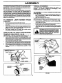
1
SEAR8
nFTZMnN°
Ik
Iv
MODEL NUMBER 944.369340
OWNER'S MANUAL
• Assembly
• Operation
• Customer
Responsibilities
• Service
• Adjustments
• Repair Parts
Caution:
Read and Follow
all Safety Rules
and Instructions
Before Operating
This Equipment
168232
REV.3
04.12.99
VB
Printed in U.S.A.
SAFETY RULES
Safe Operation Practices for Walk-Behind Mowers
IMPORTANT: THIS CUTTING MACHINE IS CAPABLE OF AMPUTATING HANDS AND FEET AND THROWING OBJECTS.
FAILURE TO OBSERVE THE FOLLOWING SAFETY INSTRUCTIONS COULD RESULT IN SERIOUS INJURY OR DEATH.
SAFETY STANDARDS REQUIRE OPERATOR PRESENCE CONTROLS TO MINIMIZE THE RISK OF INJURY. YOUR UNIT IS
EQUIPPED WITH SUCH CONTROLS. DO NOT ATTEMPT TO DEFEAT THE FUNCTION OF THE OPERATOR PRESENCE
CONTROLS UNDER ANY CIRCUMSTANCES.
TRAINING:
•
Read this operator's manual carefully, Become familiar with
the controls and know how to operate your mower properly.
Learn how to quickly stop mower.
Do not continueto runyourmower ifyou hita foreignobject.
Followthe procadumoutlinedabove,then repairany damage before restartingand operatingyou mower.
•
Do not allow children to use your mower. Never allow adults
to use mower without proper instructions.
Do not change the govemor settings or overspeed the
engine. Enginedamage or personalinjurymay result.
•
Keep the area of operation clear of all persons, especially
small children and pets.
Do notoperateyourmowerif itvibratesabnormally.Excessive vibrationis an indicationof damage; stop the engine,
safelycheckfor thecause ofvibrationand repairas required.
•
Use mower only as the manufacturer intended and as described in this manual.
Do not runthe engineindoors. Exhaustfumes are dangerous. ,
Never cut grass by pullingthe mower towardsyou. Mow
acrossthe face ofslopes, never up and down or you might
loseyourfooting.Do notmow excessivelysteepslopes. Use
caution whenoperatingthemoweron uneventerrainorwhen
changingdirections- maintaingoodfooting.
Do not operate mower if it has been dropped or damaged in
any manner. Always have damage repaired before using
your mower.
Do notuseaccessoryattachmentsthatare notrecommended
by the manufacturer. Use of such attachments may be
hazardous,
•
Never opdrate your mower withoutproper guards,plates,
grasscatcheror othersafetydevicesin place.
The blade turnswhen the engineis running.
PREPARATION:
MAINTENANCE
•
•
Check the blade and the engine mounting bolts often to be
sure they are tightened properly.
•
Check all bolts, nuts and screws at frequent intervals for
proper tightness to be sure mower is in safe working condition.
•
Keep all safety devices in place and working.
•
To reduce fire hazard, keep the engine free of grass, leaves
or excessive grease and oil.
•
Check grass catcher often for detedoration and wear and
replace wom bags. Use only replacement bags that are
recommended by and comply with specifications of the
manufacturer of your mower.
•
Always keep a sharp blade on your mower,
•
Allow engine to cool before storing in any enclosure.
•
Never store mower with fuel in the tank inside a building
where fumes may reach an open flame or an ignition source
such as a hot water heater, space heater, clothes dryer, etc.
Alwaysthoroughlycheckthearea tobe mowedandclearit of
all stones, sticks,wires, bones, and other foreignobjects.
These objectswill be thrown by the blade and can cause
severeinjury.
•
Alwayswear safetyglassesor eye shieldswhenstartingand
whileusingyourmower.
•
Dress properly. Do not operate mower when barefootor
weadng open sandals. Wear only solid shoes with good
tractionwhen mowing.
•
Check fuel tank beforestartingengine. Do not fillgas tank
iodoom, whenthe engineisrunningorwhentheengineishot.
Allowtheengine tocoolfor several minutesbeforefillingthe
gas tank. Clean off any spilledgasolinebeforestartingthe
engine.
•
•
Alwaysmake wheel heightadjustmentsbeforestartingyour
mower. Never attemptto do thiswhilethe engineis running.
Mow onlyin daylightor good artificiallight.
OPERATION:
•
•
Keep youreyes and mindon yourmowerand thearea being
cut. Do not letother interestsdistractyou.
Do not mowwet or slipperygrass. Never runwhileoperating
yourmower. Alwaysbe sureofyourfooting- keep a firmhold
on the handlesand walk.
AND STORAGE:
Look for this symbol to point out Important safety precautions.
It means
CAUTION!I! BECOME ALERTIn YOUR
SAFETY IS INVOLVED.
Do not put hands or feet near or under rotating parts. Keep
clear of the discharge opening at all times.
&
Always stop the engine whenever you leave or are not using
your mower, or before crossing driveways, walks, roads, and
any gravel-covered areas.
Never direct discharge of matedal toward bystanders nor
allow anyone near the mower while you are operating it.
Before cleaning, inspecting, or repairing your mower, stop the
engine and make absolutely sure the blade and all moving
parts have stopped. Then disconnect the spark plug wire and
keep it away from the spark plug to prevent accidental
starting.
2
CAUTION: Always disconnect spark plug
wire and place wire where It cannot contact
spark plug in order to prevent accidental
starting when setting up, transporting,
adjusting or making repairs.
PRODUCT
CONGRATULATIONS
on your purchase of a Sears Lawn
Mower. It has been designed, engineered and manufactured
to give you the best possible dependability and performance.
Should you experience any problem you cannot easily
remedy, please contact your nearest Sears Authorized
Service Center/Department.
We have competent, welltrained technicians and the proper tools to service or repair
this lawn mower.
Please read and retain this manual. The instructions will
enable you to assemble and maintain your lawn mower
properly. Always observe the "SAFETY RULES".
MODEL
NUMBER
SPECIFICATIONS
HORSEPOWER:
6.5
GASOLINE CAPACITY
AND TYPE:
1.25 quarts
UNLEADED REGULAR ONLY
OILTYPE (API-SF/SG):
SAE 30 (above 32°F)
SAE 5W-30 (BELOW32°F)
OIL CAPACITY:
944.369340
20 ozs.
SPARK PLUG:
(GAP: .030")
Champion RJ19LM
VALVE CLEARANCE:
INTAKE:
.004 -.008
EXHAUST: .004 - .008
SOLID.STATE IGNITION
SERIAL
NUMBER
AIR GAP:
.0125 IN.
BLADE BOLT TORQUE:
35-40 FT. LBS.
DATEOFPURCHASE
THE MODELAND SERIAL NUMBERS WILL BE FOUND
ON A DECALATTACHED TOTHE REAR OFTHE LAWN
MOWER HOUSING
YOUSHOULDRECORDBOTHSERIALNUMBERAND
DATE OF PURCHASE AND KEEP IN A SAFE PLACE
FORFUTUREREFERENCE.
MAINTENANCE
AGREEMENT
A Sears Maintenance Agreement is available on this product, Contact your nearest Sears store for details.
CUSTOMER
RESPONSIBILITIES
•
Read and observe the safety rules.
•
Follow a regular schedule in maintaining, cadng for and using your lawn mower.
•
Follow the instructions under"Customer Responsibilities"and "Storage" sections of this owner's manual.
3
TABLE OF CONTENTS
SAFETY RULES ...........................................................
2
PRODUCT SPECIFICATIONS .......................................
3
CUSTOMER RESPONSIBIUTIES
....................... 3,10-13
WARRANTY ..................................................................
4
ASSEMBLY ...................................................................
5
OPERATION ...............................................................
6-9
MAINTENANCE SCHEDULE .......................................
10
SERVICE AND ADJUSTMENTS .................................
14
LIMITED
STORAGE ...................................................................
15
TROUBLESHOOTING .................................................
16
REPAIR PARTS - LAWN MOWER .......................... 18-21
REPAIR PARTS - ENGINE ...................................... 22-25
PARTS ORDERING/SERVICE ....................................
26
TWO (2) YEAR WARRANTY
ON CRAFTSMAN
POWER
MOWER
For Two (2) years from date of purchaseSears Canada, Inc.will repair or replaceat Sears optionfree of chargeparts which
are defectiveas a resultof matedalor workmanship.
COMMERCIAL OR RENTAL USE:
Warrantyon Power Mower (Gas) willbe ninety(90) daysfrom date of purchaseif used for commercialor rental purposes.
This Warranty does NOT cover:
1. Pre-dellvery set-up.
2. Expendable Items which become worn duflng normal use, such as rotary mower blades, blade adapters, belts,
filters and spark plugs.
3. Repairs necessary because of operator abuse or negligence, Including bent crankshafts and the failure to
operate and maintain the equipment according to the instructions contalnnd in the Owner's Manual.
Warranty service is available by returningthe CraftsmanPower Mower to the nearest Sears Service Centre/Departmentin
Canada. This warrantyappliesonlywhilethis productis in use in Canada.
This warrantyis in additionto any statutorywarrantyand does not exclude or limit legal rightsyou may have but shall run
concurrentlywith applicable provinciallegislation. Furthermore,some provincesdo NOT allow limitationon how long an
impliedwarrantywilllast so the above limitationsmay notapply to you.
SEARS CANADA, INC., TORONTO, ONTARIO M5B 2B8
4
ASSEMBLY
Read these instructionsand this manual in its entiretybefore
you attempt to assemble or operate your new lawn mower.
IMPORTANT: THIS LAWN MOWER IS SHIPPED WITHOUT
OIL OR GASOLINE IN THE ENGINE.
TO INSTALL AI"rACHMENTS
Your lawn mower was shipped ready to be used as a
mulcher. To convert to bagging or discharging; See
OPERATION section of this manual
Your new lawn mower has been assembled at the factory
with the exception of those parts left unassembled for
shipping purposes. To ensure safe and proper operation of
your lawn mower, all parts and hardware you assemble must
be tightened securely. Use the correct tools as necessary
to ensure proper tightness. All parts such as nuts,washers,
bolts, etc., necessary to complete the assembly have been
placed in the parts bag.
TO REMOVE
CARTON
•
•
•
•
TO ASSEMBLE & ATTACH GRASS CATCHER (SEE
FIGS. 2A & 2B)
•
Put grasscatcher frameinto gress bag with rigidpart of
bag on the bottom. Make sure the frame handle is
outside of the bag top.
•
Slip vinyl bindings over frame.
NOTE: Ifvinyl bindingsare too stiff, hold them in warm water
for a few minutes. If bag gets wet, let it dry before using.
•
Close the lift top lid. Lift top lid must be closed while
operating lawn.mower.
•
Lift the rear on the mower and place the grass catcher
frame hooks into the slots of the rear door.
LAWN MOWER FROM
Remove loose parts included with mower.
Cut down two end corners of carton and lay end panel
down flat,
Remove all packing materiels except padding between
upper and lower handle and padding holding operator
presence control bar to upper handle.
Roll lawn mower out of carton and check carton
thoroughly for additional loose pads.
•
The grass catcher issecured tothe lawn mower housing
when the rear door is lowered onto the grass catcher
frame.
&
HOWTO SET UPYOUR LAWN MOWER
TO UNFOLD HANDLE (SEE FIG. 1A & 1B)
CAUTION: Do not run your lawn mower
without mulcher plug In place or grass
catcher in place. Never attemptto operate
the lawn mower with the rear door
removed or propped open
IMPORTANT:
UNFOLD HANDLE CAREFULLY
SO AS
NOT TO PINCH OR DAMAGE CONTROL CABLES.
•
•
•
•
Raise lower handle section to operating position and
squeeze the bottom ends of lower handletowards each
other until the pin in handle can be inserted into one of
the three height adjustment holes.
Removeprotective padding, raise upper handle secUon
tooperating position and tighten handle knobssecurely.
Remove any packing material from around control bar.
Your handles may be adjusted for your mowing comfort.
Refer to Service and Adjustments section of this
manual.
CATCHER
FRAME
HANDLE
OPERATOR PRESENCE
CONTROL BAR
FRAME
OPENING
UPPER
LIFT UF
RG.2A
REAR DOOR
SLOTS
MOWING POSITION
LOWER HANDLE
FIG. 1A
HANDLE
PIN
SUPPORT
BRACKET
f
GRASS
CATCHER
FRAME
HOOK
3-POS_ION
HANDLE
ADJUSTMENT
BRACKET
FIG. 2B
FIG. 1B
5
OPERATION
KNOW YOUR LAWN MOWER
READ THIS OWNER'S MANUAL AND SAFETY RULES BEFORE OPERATING YOUR LAWN MOWER. Compare the
illustrationswith your lawn mower tofamiliarize yourself with the location ofvarious controlsand adjustments. Savethis manual
for future reference,
_
, ,
Thesesymbols mayappear on your lawn mower or in literature suppliedwiththe product. Learn and understandtheir meaning.
CAUTION
OR WARNING
ENGINE
ON
ENGINE
OFF
FAST
SLOW
CHOKE
FUEL
OIL
DANGER, KEEP HANDS
AND FEET AWAY
DRIVE CONTROL BAR
PRESENCE CONTROL BAR
ENGINE
DRIVE SPEED'CONTROL
LEVER
ZONE CONTROL
STARTER HANDLI
HANDLE KNOB
GRASS CATCHER
GAS
PRIMER
WHEEL
ADJUSTER
MULCHER PLUG
OIL
MULCHER
IMPORTANT:
THIS LAWN MOWER IS SHIPPEDWlTHOUT
OIL OR GASOLINE
IN THE ENGINE.
LAWN
MOWER
HOUSING
MEETS CPSC SAFETY REQUIREMENTS
Sears rotary walk-behind power lawn mowers conform to the safety standards of the American National Standards Institute
and the U.S. Consumer Product Safety Commission. The blade turns when the engine is running.
OPERATOR PRESENCE CONTROL BAR - must be held
down to the handle to start the engine. Re ease to stop the
engine.
PRIMER - pumps additional fuel from the carburetor to the
cylinder for use when starting a cold engine.
MU LCHER PLUG - located at the discharge opening, must
be removed when converting to bagging operation.
STARTER HANDLE - used for starting the engine.
6
OPERATION
The operation of any lawn mower can result in foreign objects thrown into the eyes, which can
result in severe eye damage. Always wear safety glasses or eye shields while operating your
lawn mower or pedorming any adjustments or repairs. We recommend wide vision safety mask
over spectacles or standard safety glasses.
HOW TO USE YOUR
GROUND DRIVE SPEEDS
LAWN MOWER
(See Rg. 4A)
Your lawn mower providesmultiplespeeds to letyou selectthe
speed that suitsyou best.
CAUTION: Do not run your lawn mower
without mulcher plate in place and door
closed or approved clipping deflector or
grass catcher in place. Never attamptto
operate the lawn mower with the rear
door removed or propped open.
•
•
•
NOTE! Do not mQve speed control lever unless the engine
is running
ENGINE SPEED
The engine speed was set at the tactory for optimum
performance. Speed is not adjustable.
ENGINE
ZONE
Lowerspeeds are for, heaw/th'P..,kgrass¢_ing or trimming.
Medium speeds are for non-naigrasscutting or trimming.
High is for light cutting and for ground transport.
TO OPERATE DRIVE SYSTEM
(SEE RGS. 4A & 4S)
•
W_h engine runningselectgroundspeed bymovingspeed
controlleverto desiredposition.
•
To startforward motion,pulldrive controlbar back against
handle.
•
To stopforward motion,release ddvecontrolbar.
IMPORTANT: ALWAYS KEEP DRIVE CONTROL BAR FULLY
ENGAGEDAGAINSTHANDLEWHEN IN USE.
CONTROL
CAUTION: Federal regulations require
an engine control to be Installed ORthis
lawn mower In order to minimize the
dek of blade contact injury. Do not under
any circumstances attempt to defeat the
function of the operator control. The
bladeturns when the engine Is running.
•
Your lawn mower is equipped with an operator presence
control barwhich requires the operator to be positioned
behind the lawn mower handle to start and operate the
lawn mower.
TO ADJUST CU'I-FING HEIGHT (SEE FIG.3 )
•
All four wheels are adjusted by a single lever.
•
Pull adjuster lever toward wheel.To ralee mower, move
lever forward to desired position,To tower mower, move
the lever toward the rear.
DRIVE SPEED
CONTROL
LEVER
LOWER
WHEELS
FOR _GH
CUT
WHEEL
ADJUSTER--s-
FIG. 4A
DRIVE CONTROL
ENGAGED
OPERATOR
PRESENCE
CONTROL
BAR
FIG. 3
_
DRIVE
CONTROL
DISENGAGED
FIG. 4B
7
OPERATION
TO CONVERT MOWER
Your lawn mowerwas shipped ready to be used as a mulcher.
To convert to bagging or discharging:
REAR BAGGING (See Fig. 5A) •
Openreardoorandremovemulcherplug.
Storemulcher
plug in a safe place.
•
You can now install grass catcher.
•
To convert to mulching or discharging operation, install
mulcher plug into rear discharge opening of mower.
SIDE DISCHARGING (See Fig. 5B) •
Mulcher plug must be installed into rear discharge
opening of mower (see above instructions).
•
Open mulcherdoor and installdischarge deflector under
guard as shown.
•
Mower is now ready for discharging operation.
•
To convert to mulching or bagging operation, discharge
deflector must be removed and mulcher door must be
closed.
OPEN
MULCHER
DOOR
DISCHARGE
DEFLECTOR
SIMPLE STEPS TO REMEMBER
WHEN CONVERTING YOUR LAWN MOWER
FOR MULCHING•
•
Rear mulcher plug installed.
Mulcher door closed.
FOR REAR BAGGING •
•
•
Rear mulcher plug removed.
Grass catcher installed.
Mulcher door closed.
FIG. 5B
TO EMPTY GRASS CATCHER
(SEE FIG. 6)
•
Lift up on grass catcher using the frame handle.
•
Remove grass catcher with Clippingsfrom under lawn
mower handle.
FOR SIDE DISCHARGING •
Rear mulcher plug installed.
Side discharge deflector installed.
•
Emptyclippings from bag using both frame handle and
bag handle.
NOTE: Do not drag the bag when emptying; it will cause
unnecessarywear.
without rear mulcher plug in place or
CAUTION: DO
approved
grass
not run
catcher
your lawn
In mower
place.
Never attempt to operate the lawn mower
with the rear door removed or propped
open.
BAG
HANDLE
FRAME
MULCHER
CATCHER
HANDLE
PLUG
FIG. 5A
FIG. 6
BEFORE
STARTING
OIL (SEE FIG. 7)
ENGINE
Your lawn mower is shipped without oil in the engine.
•
Be sure mower is level and area around oil fill isclean.
•
Remove engine oil cap and fill to the full line on the
dipstick.
MULCHER
DOOR
8
OPERATION
MOWING TIPS
NOTE: Allow oil to settle down into engine for accurate
dipstick reading.
•
Engine holds 20 ozs. of oil. For type and grade of oil
to use, see 'ENGINE" in Customer Responsibilities
section of this manual.
•
Pour oil slowly. Do not over fill.
•
Check oil level before each use. Add oil if needed. Fill
to full line on dipstick.
•
To read proper level, tighten engine oil cap each time.
•
Reinstallengine oilcap and tighten.
•
Changethe oilafter every25 hours of operation oreach
season. You may needto change the oil more often
under dusty, dirty conditions.
GAS (SEE FIG. 7)
•
Fill gasolinetankwith fresh, clean, unleaded gasoline.
DO NOT USE PREMIUM GASOLINE. BE CAREFUL
NOT TO OVER FILL TANK.
WARNING: Experience indicatesthat alcohol blended fuels
(called gasohol or using ethanol or methanol) can attract
moisture which leads to separation and formation of acids
during storage. Acidic gas can damage the fuel system of
an engine while in storage. To avoid engine problems, the
fuel system should be emptied before storage of 30 days or
longer. Drainthe fueltank, startthe engine and letit run until
fuel lines and carburetor are empty. Use fresh fuel next
season. See Storage Instructionsfor additional information.
Never use engine orcarburetor cleaner products infueltank
or permanent damage may occur.
GASOLINE
CAP
•
•
•
•
Formost cuttingcondiUonsand betterbegging performance
the engine speed should be set in the fast pest on.
Under certain conditions such as when mowing verytall
grass, ra se the mower height on the first cut to reduce
pushing effort, to avoid overheating the engine, and to
avoidleaving clumpsofgrassclippings. Makethesecond
cut to the desired height.
For extremely heavy cutting, reduce the width of cut.
Forside dischargelawn mowers,cut ina counterclockwise
direction, starting at the outside of the area to be cut, in
orderto spreadgrassclippingsmore evenly and toput ess
load on the engine. To keep clippings off of walkwavs
•
.
,r
flower beds, etc., make the f rst cuts in a clockwtse
direction.
•
Pores in clothgrass catchers can become filled with dirt
and dust with use and the catcher will collect less grass.
To prevent this, regularly hose catcher off with water and
let dry before use.
MULCHING MOWING TIPS
IMPORTANT:
FOR BEST PERFORMANCE,
KEEP MOWER
HOUSING FREE OF BUILT-UP GRASS AND TRASH. SEE
"CLEANING"
IN MAINTENANCE
SECTION
OF THIS
MANUAL.
•
The special mulching blede will recurthe grass clippings
many times and reduce them in size so that as they fall
onto the lawn they will disperse into the grass and not
be noticed. Also, the mulched grass will biodegrade
quicklyto provide nutdents for the lawn. Always mulch
with your highest engine (blade) speed as this will
provide the best recutting action of the blades.
•
Avoid cutting your lawn when it iswet. Wet grasstends
to form clumps and interferes with the mulching action.
The best time to mow your lawn is the early afternoon.
At this time the grass has dded and the newly cut area
will not be exposed to the direct sun.
•
For best results, adjust the lawn mower cutting height
so that the lawn mower cuts off onlythe top one-third of
the grass blades (See Fig. 8). If the lawn is overgrown
it will be necessary to raise the height of cut to reduce
pushing effort and to keep from overloading the engine
and leavingclumps of mulched grass. For extremely
heavy mulching, reduce your width ofcut by overlapping
previously cut path and mow slowly.
•
Certaintypesofgrassandgrassconditionsmayrequire
that an area be mulched a second time to completely
hide the clippings. When doing a second cut, mow
' across or perpendicular to the first cut path.
•
Changeyourcuttingpatternfromweektoweek.
Mow
north to south one week then change to east to west the
next week. This will help prevent matting and graining
of the lawn.
FILLEI
ENGINE OIL CAP
(DISCARD DEBRIS
PLUG INSIDE)
FIG. 7
TO START ENGINE
•
To start a cold engine push primer five (5) times before
try ng to start. Use a firm push. This step is not usually
necessary when startingan engine whichhas already run
for a few minutes..
•
Holdoperator presencecontrol bar downtothe handle and
pull starter handle quickly. Do not allow starter rope to
snap back.
•
To stop engine, release operator presence controlbar.
NOTE_ Incooler weather itmay be necessaryto repeat pdming
steps. Inwarmerweatherover primingmaycause flooding and
_en_]ine
willnot start. Ifyou do flood engine, wait a few minutes
tore attempting to start and do not repeat pdming steps.
FIG. 8
9
CUSTOMER RESPONSIBILTIES
(_
Check for Loose Fasteners
Clean/Inspect
Grass Catcher
qJ/
(If Equipped)
Lawn Mower
Clean Under
Drive Cover
_
_'
Check
ddve beWpulleys
(Power-Propelled
Mowers)
i (Power-Propelled
Mowers)
W
R i Check/Sharpen/Replace
_S'
Blade
Check Engine Oil Level
Change Engine Oil
Clean Air Filter
G
I
1
2
3
4
_
Change
Service
Replace
Charge
If
_
If#'4
V=
LI
v"
Clean or Replace Spark Plug
Replace Air Filter Paper Cartridge
-
t# _
_1.2
Inspect Muffler
N
•
V*3
Lubrication Chart
Clean Battery/Recharge
IElectric Start Mowers I
E
I,/
If2
more often when operating under a heavy load or in high ambient temperatures.
more often when operating in dirty or dusty conditions.
blades more often when mowing in sandy soil.
48 hours at end of season.
GENERAL
i
LUBRICATION
RECOMMENDATIONS
CHART
(_) WHEEL
ADJ
The warranty on this lawn mower does not cover items that
have been subjected to operator abuse or negligence. To
receive full value from the warranty operator must maintain
mower as nstructed in this manual.
Some
adjustments
will need to be made
periodically
to
propedy maintain your unit.
All adjustments in the Service and Adjustments section of
this manual should be checked at least once each season.
•
Once ayear, replace the spark plug,clean or replace air
filter element and check blade for wear. A new spark
plug and clean/new airfilter element assures proper airfuel mixture and helps your engine run better and last
(_
longer.
•
Follow the maintenance
BEFORE EACH USE
schedule
in this manual.
BRAKE
SPRING
BRACKET
ENGINE
OIL
•
Check engine oil level.
•
Check for loose fasteners.
LUBRICATION
Keep unit well lubricated (See "LUBRICATION CHART").
BRACKET
MOUN_NG PIN
REAR
DOOR
HINGE
(_ SPRAY LUBRICANT
(_REFER TO CUSTOMER RESPONSIBILITIES "ENGINE" SECTION.
IMPORTANT: DO NOT OIL OR GREASE PLASTIC WH EEL
BEARINGS. VISCOUS LUBRICANTS WILL ATTRACT
DUST AND DIRT THAT WILL SHORTEN THE LIFE OF THE
SELF LUBRICATING BEARINGS. IF YOU FEEL THEY
MUST BE LUBRICATED, USE ONLY A DRY, POWDERED
GRAPHITE TYPE LUBRICANT SPARINGLY.
10
CUSTOMER
RESPONSIBILITIES
LAWN MOWER
•
*
Always observe safety rules when performing any
maintenance.
TIRES
•
Keep tiras free of gasoline, oil, or insectcontrolchemicals
which can harm rubber.
•
Avoid stumps, stones, deep ruts, sharp objects and
other hazards that may cause tire damage.
BLADE CARE
For bast results, mower blade must be kept sharp. Replace
bent or damaged blades.
_
f
_,_
TO REMOVE BLADE (SEE FIG. 9)
•
Disconnect spark plug wire from spark plug and place
wire where it cannot come in contact with spark plug.
•
Turn lawn mower on its side. Make sure air filter and
carburetor are up.
•
Use a wood blockbetween blade and mower housing to
prevent blade from turning when removing blade bolt.
•
Protect your hands with gloves and/or wrap blade with
heavy cloth.
•
Remove blade bolt byturning counter-clockwise,
•
Removeblade and attaching hardware (bolt, iockwasher
and hardenedwasher).
NOTE: Remove the blade adapter and checkthe key inside
hub of blade adapter. The key must be in good conditionto
work properly. Replace adapter if damaged.
BL'ADEI
LOCK
WASHER
X
_
\
_'_
ING
EDGE
FIG. 9
TO REPLACE BLADE (SEE FIG. 9)
•
Positionthebladeadapterontheenginecrankshaft.
Be
sure key in adapte rand crankshaft keyway are aligned.
•
Position blade on the blade adapter aligning thetwo (2)
holes in the blade with the raised lugs on the adapter.
•
Be sura the trailing edge of blade (opposite sharp edge)
is up toward the engine.
•
Installthe blade bolt with the Iockwasher and hardened
washer into blade adapter and crankshaft.
•
Use block of wood between blade and lawn mower
housing and tighten the blade bolt, turning clockwise.
•
The recommended tightening torque is 35-40 ft. Ibs.
IMPORTANT: BLADE BOLT IS GRADE 8 HEATTREATED.
TO SHARPEN BLADE
NOTE: We do not recommend sharpening blade- but if you
do, be sure the blade is balanced.
Care should be taken to keep the blade balanced. An
unbalanced blade willcause eventual damage to lawn mower
orengine.
•
The blade can be sharpened with a file or on a grinding
wheel. Do not attempt to sharpen while on the mower.
•
To check blade balance, drive a nail into a beam orwall.
Leave about one inch of the straight nail exposed.
Place center hole of blade over the head of the nail. If
blade is balanced, it should remain in a horizontal
position. If either end of the blade moves downward,
sharpen the heavy end until the blade is balanced.
GRASS CATCHER
•
The grass catcher may be hosed with water, but must
be dry when used.
•
Check your grass catcher often for damage or
deterioration. Through normal use it will wear. If
catcher needs replacing, replace only with a
manufacturer approved replacement catcher. Givethe
lawn mower model numberwhen ordering.
BLADE
ADAPTER,_
11
,,_
o CRANKSHAFT
KEYWAY
_C_ANK-
BLADE
ArJAPTFR
CUSTOMER
RESPONSIBILITIES
DRIVE WHEELS (SEE FIG. 10)
Check rear drive wheels each time you mow to be sure they
move freely. The wheels not turning freely means trash,
grass cuttings, etc., may be inside the drive wheel and dust
cover area and must be cleaned out to free drive wheels.
ENGINE
LUBRICATION
Use only high quality detergent oil rated with API service
classification SF or SG. Select the oil s SAE viscosity grade
according to your expected operating temperature.
If necessary to clean the ddve wheels, check both rear
wheels.
•
•
•
•
•
•
•
•
SAE VISCOSITY GRADES
Remove hubcaps and Iocknuts.
Remove wheels from wheel adjuster axles.
Remove anytrash or grass cuttings from inside the dust
cover, pinion and/or drive wheel gear teeth.
If you remove the drive pinions, clean and lubricate with
spray lubricant or dry powdered graphite type lubricant
before reinstalling. Do not use oil or grease.
The pinion gear, on both sides of the mower, are the
same, however, they must be installed correctly. If
installed incorrectly, the drive system will not work.
There are arrows embossed on both sides of the pinion
gear. With the arrow at the top of the pinion, the arrow
must point towards front of mower. If the arrow points
to the rear, turn the pinion around and assemble to
mower.
Place wheels back on adjuster axles.
Replace locknuts and hubcaps.
•,30"
-20"
-10"
O"
10"
20"
30"
TEMPERATURE RANGE ANTICIPATED BEFORE NF_XTOIL CHANGE
NOTE: Although multi-viscosity oils (5W30, 10W30 etc.)
improve starting in cold weather these multi-viscosity oils
will result in increased oil consumption when used above
32°F. Check your engine oil level more frequently to avoid
possible engine damage from running low on oil.
Change the oil after every 25 hours of operation or at least
once a year ifthe lawn mower is not used for 25 hours in one
year.
Checkthe crankcase oillevel before starting the engine and
after each five (5) hours of continuous use. Tighten oil plug
securely each time you check theoil level.
TO CHANGE ENGINE OIL (See Fig. 11 )
NOTE: Beforetipping lawn mowerto drain oil drain fueltank
by running engine until fuel tank is empty.
•
Disconnect spark plug wire from sparkl_lug and place
wire where it cannot come in contact with spark plug.
•
Remove engine oil cap; lay aside on a clean surface.
•
Tip lawn mower on its side and drain oil into a suitable
container. Rocklawn mowerbackand forthto remove
any oil trapped inside of engine.
•
Wipe off any spilled oil on lawn mower and on side of
engine.
•
Fill engine with oil. Fill only to the "FULL" line on the
dipstick. DO NOT OVER FILL.
•
Replace engine oilcap.
Reconnect spark plug wire to spark plug.
CORR_CORRECT
PINION
DUSTCOVER
LOCKNL
WASHER
HUBCAP
FIG. 10
CONTAINER
FIG. 11
12
CUSTOMER RESPONSIBILITIES
AIR FILTER
MUFFLER
Inspect and replace corroded muffler as itcould create a fire
hazard and/or damage.
SPARKPLUG
Your engine will not run properly and may be damaged by
using a dirty air filter.
Replace the air filter every year, more often if you mow in
very dusty, dirty conditions. Do not wash air filter.
Change your spark plug each yearto make your engine start
easier and run better. Set spark plug gap at .030 inch.
TO CHANGE AIR FILTER (SEE FIG. 12)
•
Remove the air filter by turning clockwise to the stop
and pull away from collar.
•
Remove filter from inside of cover.
•
Clean the inside of the cover and the collar to remove
any dirt accumulation.
•
Insert new filter into cover.
•
Put air filter cover and filter into collar aligning the tab
with the slot.
•
Push in on cover and turn counterclockwise totighten.
CLEANING
IMPORTANT:
FOR BEST PERFORMANCE,
KEEP MOWER
HOUSING
FREE OF BUILT-UP
GRASS AND TRASH.
CLEAN THE UNDERSIDE OF YOUR MOWER AFTER EACH
USE. •
I_
Turn lawn mower on its side. Make sure air filter and
carburetor are up. Clean the underside of your lawn
mower by scraping to remove build-up of grass and
trash.
•
Clean engine oftento keeptrash from accumulating.A
clogged engine runs hotter and shortens engine life.
Keep finished surfaces and wheels free of all gasoline,
oil,etc.
•
•
SLOT
AIR FILTER
AIR FILTER COVER
TURN COUNTER
CLOCKWISE
TO TIGHTEN
FIG. 12
13
I
•
COLLAR
CLOCKWISE
TO REMOVE
from.spark plug and place wire where it
cannot come in contact with the spark
CAUTION:
Disconnect spark plug wire
plug,
We DO NOT recommend usin_ a garden hose to clean
lawn mower unless the electrical system, muffler, air
filter and carburetor are covered to keep water out.
Water in engine can result in shortened engine life.
SERVICE AND ADJUSTMENTS
h
CAUTION:
BEFORE PERFORMING ANY SERVICE OR ADJUSTMENTS:
ENGINE SPEED
LAWN MOWER
Your engine speed has been factory set. Do not attempt to
increase ehgine speed or itmay result in personal injury. If
you believe that the engine is running too fast or too slow,
take your lawn mower to an authorized service center for
repair and adjustment.
TO ADJUSTCUI-rlNG
HEIGHT
See "TO ADJUST CUTTING HEIGHT" in the Operation
section of this manual.
REAR DEFLECTOR
The rear deflector, attached between the rearwheels of your
lawn mower, is provided to minimize the possibility that
objects will bethrown outthe rearofthe lawn mowerintothe
operator's mowing position. If the rear deflector becomes
damaged, it should be replaced.
CARBURETOR
Your carburetor has a non-adjustable fixed main jet for
mixturecontrol. If yourengine does not operate properly due
to suspected carburetor problems, take your lawn mowerto
an authorized service center for repair and/or adjustment.
IMPORTANT:
NEVER TAMPER WITH THE ENGINE
GOVERNOR, WHICH IS FACTORY SET FOR PROPER
ENGINE SPEED. OVERSPEEDINGTHE ENGINE ABOVE
THE FACTORY HIGH SPEED SETTING
CAN BE
DANGEROUS. IF YOU THINK THE ENGINE-GOVERNED
HIGH SPEED NEEDS ADJUSTING, CONTACT YOUR
NEAREST AUTHORIZED SERVICE CENTER, WHICH HAS
PROPER EQUIPMENT AND EXPERIENCE TO MAKE ANY
NECESSARY ADJUSTMENTS.
TO ADJUST HANDLE (SEE FIG. 13)
The handle on your lawn mower has three (3) height positions
- adjust to height that suits you.
•
Squeezethe bettom ends of lower handle towards eech
other until the pin in handle can be inserted into one of
the three height adjustment holes.
J
;-POSITION
HANDLE
ADJUSTMENT
BRACKET
FIG. 13
14
STORAGE
Immediately prepare your lawn mower for storage at the end
of the season or if the unit will not be used for 30 days or
more.
LAWN
ENGINE
FUEL SYSTEM
IMPORTANT:
IT IS IMPORTANT TO PREVENT GUM
DEPOSITS FROM FORMING IN ESSENTIAL FUELSYSTEM
PARTS SUCH AS CARBURETOR, FUEL FILTER, FUEL
HOSE, OR TANK DURING
STORAGE.
ALSO,
EXPERIENCE INDICATES THAT ALCOHOL BLENDED
FUELS (CALLED GASOHOL OR USING ETHANOL OR
METHANOL) CAN ATTRACT MOISTURE WHICH LEADS
TO SEPARATION AND FORMATION OF ACIDS DURING
STORAGE.
ACIDIC GAS CAN DAMAGE THE FUEL
SYSTEM OF AN ENGINE WHILE IN STORAGE.
•
Drain the fuel tank.
•
Start the engine and let it run until the fuel lines and
carburetorare empty.
•
Never use engine orcarburetor cleaner products in the
fuel tank or permanent damage may occur.
•
Use fresh fuel next season.
NOTE: Fuel stabilizer is an acceptable alternative .in
minimizingtheformation offuel gum deposits duringstorage.
Add stabilizer to gasoline in fuel tank or storage container.
Always follow the mix ratio found on stabilizer container.
Run engine at least 10 minutes afteradding stabilizerto allow
the stabilizer to reach the carburetor. Do not drain the gas
tank and carburetor if using fuel stabilizer.
ENGINE OIL
MOWER
When lawn mower is to be stored for a period of time, clean
it thoroughly, remove all dirt, grease, leaves, etc. Store in
a clean, dry area.
•
Clean entire lawn mower (See "CLEANING" in the
Customer Responsibilities section of this manual).
•
Lubricate as shown in the Customer Responsibilities
section of this manual.
•
Be sure that all nuts, bolts, screws, and pins are
securelyfastened. Inspect movingpartsfordamage,
breakage and wear. Replace if necessary.
•
Touch up all rusted or chipped paint surfaces; sand
lightlybefore painting.
HANDLE (SEE FIG. 14)
•
You can fold your lawn mower handle for storage.
•
Loosen the two (2)handle knobs on sides of the upper
handle and allow handle to fold down to the rear.
•
Squeeze the bottom ends of lower handle toward each
other until pins in handle clear the brackets and pivot
entire handle assembly forward and allow it to rest on
mower.
Drain oil(withengine warm) and replace with clean engine oil.
(See "ENGINE" in the Customer Responsibilities section of
this manual).
CYUNDER
•
Remove spark plug.
•
Pour one ounce (29 ml) of oil through spark plug hole
into cylinder.
•
Pull starter handle slowly a few times to distribute oil.
•
Replace with new spark plug.
•
When setting up your handle from the storage position,
the lower handle will require manually locking into the
mowing position.
IMPORTANT:
WHEN FOLDING THE HANDLE FOR
STORAGE OR rTRANSPORTATION,
BE SURE TO FOLD
THE HANDLE AS SHOWN OR YOU MAY DAMAGE THE
CONTROL CABLES.
OPERATOR
CONTROL
UPPER
OTHER
PRESENCE
•
•
Do not store gasoline from one season to another.
Replace your gasoline can if your can starts to rust.
Rust and/or dirt in your gasoline will cause problems.
•
If possible, store your unit indoors and cover itto give
protection from dust and dirt.
•
Cover your unit with a suitable protective cover that
does not retain moisture. Do not use plastic. Plastic
' cannot breathewhich allows condensation toform and
will cause your unit to rust.
IMPORTANT: NEVER COVER MOWER WHILE ENGINE
AND EXHAUST AREAS ARE STILL WARM.
BAR
HANDLE
_
FOLD FORWARD
_
_,.
FOR
_
X
STORAGE
_,//_D
BACKWARD
MOWING
POSITION
LOWER HANDLE
CAUTION: Never store the lawn mower
with gasoline in the tank inside a building
where fumes may reach an open flame
or spark. AIIowthe engineto cool before
storing in any enclosure.
HIGH
PIN
3-POSITION
HANDLE
ADJUSTMENT
BRACKET
FIG. 14
15
i
TROUBLESHOOTING
i i
CAUSE
Will not start
i
CORRECTION
2.
3.
4.
Dirtyair filter,
Out of fuel.
Stale fuel.
Water in fuel.
1.
2.
3,
4,
5.
6.
7.
8.
9.
Spark plug wire is disconnected,
Bad spark plug.
Looseblade or brokanblade adapter,
Controlbar in releasedposition
Controlbar defective
5.
,6.
7,
8,
9,
1,
1,
Set In "HigherCut" position.
2.
3.
4.
5.
6.
Rear of lawn mower housing/bladedragging
in heavy grass,
Cutting too much grass,
Dirtyair filter,
Buildupof grass, leavesand trash undermower.
Too muchoilin engine.
Walking speed too fast.
2.
3.
4.
5.
6.
Set in =HigherCut" position.
ClserJreplaceair filter.
Clean undersideof mowerhousing.
Check oil level.
Cut at slowerwalkingspeed,
Poor cut- uneven
1.
2.
3.
Wom, bent or loose blade.
Low engine speed.
Buildupof grass, leaves, and trash undermower.
1.
2,
3.
Replace blade, Tightenblade bolt.
Set engine speed cantrolin fast position,
Clean undersideof mower housing.
Excessive
1,
2.
Wom, bent or loose blade,
Bent engine crankshaft.
1.
2.
Replace blade. Tightenblade bolt,
Contact an authodzed service center/department,
1.
1.
2.
3.
4.
Engine flywheel brake is on when controlbar is
released.
Bent engine crankshaft
Blade adapter broken.
Blade draggingin grass.
Depress controlbar to upper handle before
pullingstarter rope.
Contact an authodzed service canter/dapartment.
Replace blade adapter.
Move lawn mower to cut grassor to hard surface
to startengine.
Grass catcher not filling
(If so equipped)
1.
2.
3.
4.
Cuttingheighttoo low.
Lifton blade wom off.
Catcher not ventingair.
Low engine speed.
1.
2.
3,
4.
Raise cuttingheight.
Replace blade.
Clean grass catcher.
Set enginespeed controlin fast position.
Herd topush
1.
2.
1.
2.
3,
4.
Grass is too highor wheel height is too low.
Rear of lawn mowerhousing/bladedragging
in grass,
Grass catcher too full.
Handle heightpositionnot rightfor you.
3,
4.
Raisecuttingheight,
Raise rear of lawn mower housingone (t)
seffinghigher.
Empty grass catcher.
Adjusthandleheightto suit,
1.
2,
Check/replace
Check/reinstall
3,
4,
Replace ddve cable,
Clean ddve pinions.
t*
Clean/replacaair filter.
Fillfuel tank.
Draintank and refillwith fresh cleanfuel,
Drain fuel tank and carburetorand refill tank withfresh
gasoline.
Connect wire to plug.
Replace spark plug.
Tighten blade boltor replaceblade adapter.
Depresscontrolbar to handle.
Replace contmt bar.
I
Loss of power
vibration
Starter rope hard to pull
Loss of drive
1.
Belt wear.
2.
3.
Belt off of pulley,
Ddve cable worn or broken.
4.
Dirt in drive pinions.
j
POINTS
i
PROBLEM
i
16
2.
3.
4.
ddve belt.
ddve belt.
II
SERVICE NOTES
17
REPAIR
PARTS
ROTARY
LAWN MOWER
- MODEL
NUMBER
28
8
0o
41
I
944.369340
REPAIR PARTS
ROTARY
KEY
NO.
1
2
3
4
5
6
7
8
9
10
11
12
13
14
15
16
17
18
19
20
21
22
23
24
25
26
27
28
29
30
31
32
33
34
PART
NO.
167163
161105X479
131036
132001
636O1
66426
131959
87692
164265
161551
73990500
51793
161586
850733X004
83816
162085
161548
165262
168234
161568X479
168227X479
150078
163183
63124
161333
163409
161550
88652
166035X479
851514
159267
851074
850263
851084
LAWN
MOWER
DESCRIPTION
Handle, Upper DIx Comf. (Including grip)
Handle, Lower
Bail, Cont. Wire DIx Coral. BIk
Guide, Rope, Side
Nut, Hex Lockwasher 1/4-20
Wire, Tie
Bolt, Handle 5/16-18 x 1.75
Knob, Handle
Grip, Hdl Foam Smooth
Bolt, Sq. Neck
Nut, Hex Lockwasher Ins. 5/16-18 UNC
Cotter, Hairpin
Engine control
Bracket, Upstop
Screw, HexWasher HeadTapping 10-2
Kit, Door Rear
Seal, Door
Plug, Mulcher "
Kit, Housing
Handle, Bracket Asm. Left
Handle, Bracket Asm. Right
Screw, Hex Wshd
Bolt, Hex Head 5/16-18 x 5/8
Nut, Hex LockWshr 5/16-18
Baffle, Side
Screw 12 x 5/8
Skirt
Screw, Hinge 1/4-20 x 1.25
Belt Cover,Top
Adapter, Blade w/key Longer
Blade, 21"
Washer, Hardened
Lock;washer,Helical Spring 3/8 ;
Screw, Hex Head 3/8-24 x 1.38
- MODEL
KEY
NO.
NUMBER
PART
NO.
35
36
37
38
166032
166385
150406
39
40
41
45
46
47
48
49
50
51
52
53
54
55
56
57
58
59
60
61
62
63
64
65
66
67
68
---
168233
161358
107339X
166034
166041
1200014
169605
166039X007
54583
166045
166115
166037
750097
166383X479
68038
166391X004
57808
166042
166050
145212
155552
166022X007
166043
160829
166885
166028 .
88349
162300
168232
944.369340
DESCRIPTION
Pulley, Fixed
Bearing Support Assy.
Bolt, Engine .
Engine (See Breakdown)
Craftsman 143.996522
Grass Catcher Bag
Grass Catcher Frame
Danger Decal
Engagement Rod
Bushing
E-ring
Reta'merClip
Clamp
Screw
Spacer
Belleville Washer
Belt Cover, Bottom
Screw
Cable Support Bracket
Nut
Bracket Assy.
Screw
V-Groove Pulley
Idler Arm Spacer
Flange Nut
Locknut
IdlerArm
Idler Pulley
Shoulder Bolt
Door Assy.
Multi Cut Door
Nut
Warning Decal (Not Shown)
Owner'sManual
REPAIR
PARTS
ROTARY LAWN MOWER - MODEL NUMBER 944.369340
32
23
o
15
19
41
23
24
29
3O
33
34
3_
42
38
41
REPAIR PARTS
ROTARY LAWN MOWER - MODEL NUMBER 944.369340
KEY
NO.
Io
1
2
4
5
6
7
8
9
10
11
12
13
14
15
16
17
18
19
20
21
22
23
24
PART
NO.
166047
167259
167498
161537
750634
166060
132010
166049
166021X004
17541011
166189
166388
145354
57079
161684X479
161602
160477X004
167650
12000022
163365
166849
161118X004
578O8
DESCRIPTION
Speed Control
Bail Control Drive
DdveCable
Cover Drive
Screw Thdro110-25 x .50
V-Belt
Nut Lock Flanged 3/8-16 Zinc
Pulley Driven
Belt Keeper Bracket
Screw Hex Wash Head 10-24 X .668
Pivot Rod Cover
Transmission Asm.
Pin Spring Thrust
WasherHardened
Rod Connecting
Spring Extension
Spring Selector
Knob Selector Spring
E-Ring7/8
Searing Support
Bearing Ball
Retainer Drive Asm, Stmp,
Screw Hex Head Tapping 1/4-20 x.75
KEY
NO.
25
26
27
28
29
30
32
33
34
35
35
37
35
39
40
41
42
43
44
45
PART
NO.
T66453
166450
52160
12000058
88080
67725
150342
145212
150181
160785X004
160786X004
161463
163409
700279
150339
150182
83923
19572216
144929
751152
DESCRIPTION
Drive Pawl
Pinion, Drive
Washer
E-Ring 7/16
Cover, Dust Wheel
Washer 1/2x1-1/2
x.134
Wheel 9 x 2
Nut Hex Flange Lock
Hubcap, Mag Platinum 9"
ShaftAsm. Rear
Shaft Asm. Front
Retainer Front Shaft
Screw 12x5/8
Clip Retainer
Wheel 8 x 2
Hubcap, Mag Platinum 8"
Nut, Hex Flange Lock 3/8-16
Washer
Screw 1/4 x 2.12
Locknut
CRAFTSMAN 4-CYCLE ENGINE
MODEL
NO.143.996522
i
261 287
260
370C
4OO
• 285
135
130
120
119
125
45
182
22
46
iI
I
CRAFTSMAN 4-CYCLE ENGINE
KEY PART
NO. NO.
DESCRIPTION
1
2
6
7
12A
12B
14
15
16
17
18
19
26
30
40
4O
40
41
41
Cylinder (Incl. 2,7,20 & 125)
Dowel Pin
Breather Element
Breather Ass'y. (Incl. 6 & 12A)
Breather Cover & Tube (Incl. 12B)
BreatherTube Elbow
Washer
Governor Rod (Incl. 14)
Govemor Lever
Governor Lever Clamp
Screw, Torx T-15, 8-32 x 19/64"
Extension Spring
Oil Seal
Crankshaft
Piston, Pin & Ring Set (Std.)
Piston, Pin & Ring Set (.010" OS)
Piston, Pin & Ring Set (.020" OS)
Piston & Pin Ass'y. (Std.) (Incl. 43)
Piston & Pin Ass'y. (.010" OS) (Incl.
36478A
26727
33734
36557
36558
34695
28277
3O589
34839A
31335
651018
36281
326OO
34670A
36073
36O74
36075
36070
36071
KEY PART
NO. NO.
169 27234A
172 32755
174 30200
178 29752
182 6201
184 26756
165 36544
186 32653
189 650839
191 35559A
195 6_0973
267 34336
216 33086
223 650451
224 34690A
238 650932
239 34338
241 36919
246 36905
250 36920
260 36915
261 30200
262 650831
263A 37184
275 36473
277 650956
265 35000A
287 650926
290 29774
292 26460
298 28763
300 35916
301 36246
305 35647
306 36996
307 35499
309 650562
310 35648
313 34080
347 651038
370A 36261
370C 37199
380 632747
390 590739
400 36481B
41,6 36085
43)
41
36072
42
42
42
43
46
46
46
5O
52
69
70
36076
36O77
36078
20381
32875A
32610A
27241
35992
29914
35261
34311E
72
73
75
80
81
82
83
86
89
90
92
93
100
101
103
110
119
120
125
125
126
126
130
135
150
151
30572
28833
27897
30574A
30590A
3O591
35588A
650488
611004
611112
650815
650816
34443B
610118
651007
37047
36477
36476
36471
36472
29314C
29315(3
6021A
35395
31672
31673
MODEL
NO.143.996522
Piston & Pin Ass'y. (.020" OS) (Incl.
Ring Set (Std.)
Ring Set (.010" OS)
Ring Set (.020" OS)
Piston Pin Retaining Ring
Connecting Rod Ass'y. (Incl. 46)
Connecting Rod Bolt
Valve Lifter
Camshaft (MCR)
Oil Pump Ass'y.
* Mounting Flange Gasket
Mounting Flange (Incl. 72 thru
83,306)
Oil Drain Plug (Incl. 73)
Drain Plug Gasket
Oil Seal
GovernorShaff
Washer
Govemor Gear Ass'y. (Incl. 81)
GovemorSpool
Screw, 114-20 x 1-1/4"
Flywheel Key
Flywheel
Belleville Washer
Flywheel Nut
Solid State Ignition
Spark Plug Cover
Screw, Torx T-15, 10-24 x 15116"
GroundWire
* Cylinder Head Gasket
Cylinder Head
Exhaust Valve (Std.) (Incl. 151)
Exhaust Valve (1/32" OS) (Incl. 151)
Intake Valve (Std.) (Incl. 151)
Intake Valve (1/32" OS) (Incl. 151)
Screw, 5/16-18 x 1-1/2"
ResistOr Spark Plug (RJ19LM)
Valve Spring
Valve Spring Cap
417 650821
900 ---900 -- --
DESCRIPTION
* Valve Cover Gasket
Valve Cover
Screw, 10-24x9/16"
Nut & Lock Washer, 1/4-28
Screw, 1/4-28 x 7/8"
CarburetorTo Intake Pipe Gasket
Intake Pipe
Governor Link
Screw, 1/4-20x3/8"
S.E. Brake Bracket (incl. 195)
Terminal
Throttle Link
R.P.M. Adjusting Lever
Screw, 1/4-20 x 1"
* Intake Pipe Gasket
Screw, 10-32 x 49/64"
* Air Cleaner Gasket
Air Cleaner Collar
Air Cleaner Filter
Air Cleaner Cover
Blower Housing
Screw, 10-24 x 9/16"
Screw, 1/4-20 x 1/2"
Starter Grill
Muffler (Incl. 277)
Screw, 1/4-20x2-5/16"
StarterCup
Screw, 8-32 x21/64"
Fuel Line
Fuel Line Clamp
Screw, 10-32 x 35/64"
Fuel Tank (Incl. 292 & 301)
Fuel Cap
Oil Fill Tube
*"O"-Ring
"O"-Ring
Screw, 10-32 x 1/2"
Dipstick
Spacer
Screw, 10-32x51/64"
Lubdcetion Decal
Primer Decal
Carburetor(IncL 184)
Rewind Starter
Gasket Set (Incl. Items Marked *)
Spark Arrestor Kit (Incl.
417)(Optional)
Screw, 10-32 x 1/2" (Optional)
Replacement Engine NONE
Replacement Short Block 750729C,
order from 71-999
RPM High 3000 to 3300
NOTE:: This engine could have been built with 590702
starter
NOTE: All component dimensions given in U.S. inches
1 inch = 25.4 mm
23
CRAFTSMAN 4-CYCLE ENGINE
MODEL
NO.143.996522
_'%3/
4O
KEY PART
NO. NO.
DESCRIPTION
-- -1
2
4
5
6
7
16
25
27
28
29
30
31
35
36
37
40
44
48
Carburetor (Incl. 184 of Engine Parts List)
Throttle Shaft & Lever Assembly
Throttle Return Spring
Dust Seal Washer
Dust Seal (Throttle)
Throttle Shutter
ShutterScrew
Fuel Fitting
Float Bowl
Float Shaft
Float
Float Bowl "O" Ring
Inlet Needle, Seat, & Clip (Incl. 31)
SpringCUp
Primer Bulb/Retainer Ring
Main Nozzle Tube
"O" Ring, Main Nozzle Tube
High Speed Bowl Nut
Bowl NutWasher
Welch Plug, Atmospheric Vent
632747
631615
631767
631184
631183
6325O4
65O5O6
631807
631867
631024
632019
631028
631021 •
631022
36045A
632735
632547
632736
27110
631027
24
CRAFTSMAN 4-CYCLE ENGINE
MODEL
NO,143.996522
' I
ml
KEY PART
NO. NO.
-- -1
2
3
4
5
6
7
8
11
590702
590599A
5906OO
590696
590601
59O697
590698
590699
590700
590703
12
13
590535
590701
DESCRIPTION
Recoil Starter
Spring Pin (Incl. 4)
Washer
Retainer
Washer
BrakeSpdng
StarterDog
Dog Spring
Pulley & Rewind Spring Ass'y.
Starter Housing Ass'y. (40 degree
grommet)
Starter Rope ( 98" X 9/64" dia.)
Starter Handle
m5
Ore2
_t4
KEY PART
NO. NO.
13
_8
!1
Ill m7
25
-- -3
I_
7
8
11
590739
590740
590616
590617
590618A
590638
12
590535
13
14
590701
590760
DESCRIPTION
Rewind Starter
Retainer
StarterDog
Dog Spring
Pulley & Rewind Spring Ass'y
Starter Housing Ass'y (40 degree
_rommet)
tarter Rope (Length 98" x 9/64
alia.)
Starter Handle
SpringClip
OWNER'S
MANUAL
£RRFTSHRNo
6.5 HORSEPOWER
21" MULTI-CUT
POWER PROPELLED
ROTARYLAWN MOWER
Each lawn mower has its own" model number. Each engine has its own
model number.
MODEL NO.
944.369340
The model number for your lawn mower will be found on a decal attached
to the rear of the lawn mower housing.
The model number for your engine will be found on the blower housing of
the engine.
All parts listed herein may be ordered from any Sears Canada, Inc. Service Centre/Department and most Retail Stores.
WHEN ORDERING REPAIR PARTS, ALWAYS
ING INFORMATION:
HOW TO ORDER
REPAIR PARTS
•
PRODUCT - LAWN MOWER
•
MODEL NUMBER - 944.369340
•
ENGINE MODEL NO.- 143.996522
•
PARTNUMBER
•
PART DESCRIPTION
GIVE THE FOLLOW-
Your Sears merchandise has added value when you consider Sears has
service units nationwide staffed with Sears trained technicians...
professional technicians specifically trained to insure that we meet our
pledge to you, we service what we sell.
NEED A PART?
SEARS HAS ACCESS TO OVER 800,000 PARTS
WHETHER IT'9 A SPARK PLUG OR LAWNMOWER BLADE.
SEARS PARTS AND SERVICE CAN SUPPLY YOU WITH
TOP QUALITY REPAIR PARTS FOR ALL YOUR PRODUCTS.
JUST CALL ONE OF THE FOLLOWING NUMBERS TO PLACE YOUR
ORDER. IF CALLING LOCALLY:
Regina - 566-5124
Montreal - 333-5740
Toronto - 744-4900
Halifax - 454-2444
Kitchener - 894-7590
Ottawa - 738-4440
Vancouver - 420-8211
ALL OTHER AREAS CALL 1-800-665-4455
26