1
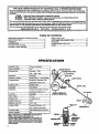
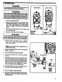
IMPORTANT
MAI'_AL
Do Not Throw Away
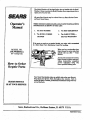
Operator's
Manual
MODEL NO.
358.799260132cc
(I8" Cntting Path)
Always Wear Eye Protection
/CRR.FTSMRN
.
_z-soo-_35-SsTS
32ccGAS
& W_G:
* Maintenance
• ReD,_. Parts,
* Assembly
Instructions.
* Operation
FaiiareToDoSoCaaRm_
®
lhld Mix 40:1
2 Cyde Engine
and Follow All Warnings
and S_ety
WEEDWACKER
inStr!_ hC,a_
•:
.........
.
..
.
•
i ill I
o
- ILl[Jt!t_t-r
.
'
Jllut
Sears,Roebuck.and C.o.,HoffmanEstates,IL 60179 U.S.A.
_30-08242_-i4_./12/94
"
® 1994, Sears, Roebuck and Co.
= ....... -_ ......... .
i
i_
iii:ii_- ::::7 7
whe_t_ _.c-_-_w_
n_m_ance
mm-uc_s
a_ follows:
1 YEAR
"
Lmn D
:=;;;;;;;;;
,L
-.
ON
_
w._.a_er_ mm_ed, lubber, _.dt_
m me operator's
manure, _ars
......
-:
:
C -POWZR VE WAC Za®
up_g_
theo_" g_d
wm repair, free of c]_rge, any defect in m_
or wor_
- Parts and Labor, w.hen used forhousehold purlms_.
90 DAYS - Parts and Labor, if used for commercial, insti_ational,
30 DAYS - Parts and Labor, if used for rental purposes.
This warrantyexeahi.des
nylonline,
sparkplug,and air_
or professional purposes.
whicham expendablepartsand become worn duringnormaluse.
This w at'_n_appl_ only while tl_ pz_tuct i_in use in the United Stat_. WARRANTY S_WIG-_IISAVAILABLEBYRETURNING THE
WEEDWACKERTO _
_
SEA_ SEleCtS _R_DEPARTMENT
IN THE UNI_D _ATES.
Thiswerrantygives
you Slmdfie
ieilal
riglxta,
andyoumay alsohaveotherri_tswhichvaryfromstate
tostate.
SEAR_I_OF_2BUG'_ANDOOL
D_P'JRSI_VA . HO_E_TES,
IL 601ff9
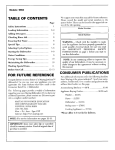
TAB_
OF CONTENTS
WARNINGS AND _.FETY INSTRUCTIONS ..............
.3
L_ING YOUR UNIT...................................................
12
CUSTOMER RF_PONSIBILITIES ............................. 16
KNOW YOUR UNIT .....................................................
ASSEMBLY ..................................................................
6
STORAGE .................................................................
21
ACCEb'SORIES ............................................................
9
ILLUSTRATBD PARTS LIST .....................................
23
FUELING YOUR ENGINE .................. :...................... 10
INDEX ...................................................
26
STARTING YOUR ENGINE .......................................
11
SPECIFICATIONS
._
._NGINE TYPE:
! D[SPLACEMKNT:
2._ycle, Air--Cool_'d
32cc
-ENGINE RPM:
Operating"
7500
Idle -- 2800- 3200
IGNITION:
Solid Stale
IGNITION TIMINGi
•
..
=..............
iSpark Advance _
Non-adjustable
_
CARBURETOR:
!Diaphragm Ai! Positions with
adjustable _!
v.rqO_NEi,_O_F':
....
mixture jets
! pgsmye
Swath
STARTF-.R: -
!Auto Rewind
MUFFLER:
Temperature Limiting (not spa&
an_ing:
..........
SPARK PLUG:
....
.
sP^_: PLUG
GAP'MODULE: A(R GAP:
LUBRICATION:
see Notice. p. 6)
l 7 fl, oz.
171-_5854(CJ-t4}
....
.o2s"
......
.010" /.014';
'
"
'_G_'_o!ineiOff Mixture- 40: |
: '
- ",080" Diamctcr'Sears Laser Line"
[(See "FuelingYour Engine"]
CUTTING ILANEi
.....
.........
.....................
:
SHAFT LENGTH• NO_ _UN_
[SA _
WHrfE CONSOLI_T_D IN--KS,
M,MqUFACIX/_
_
---
,
52"
ONE
OR
_
....
_¢DEMARKOF
IN_
OF I"F_
FO_O
U.S.
I_.T_9_SPf_NgII_.
2.
PLUG
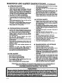
A WARNINGSAND SAFETY INSTRUCTIONS
(SeeAdditio_ SsfetyInst_ions t_=oughoutthisManual)
'_ WARNING
- TH!S PO_
TOOL CANB£ DANGEROUS! _
uuitca__u_e _erio_
in_,y or blindness to the operator and others. The warnings andsafety instructions in this manual must be lot..towedto pre_ide_reasone_iesafety aud_efficiencyiu us.mg,.__uni_The_o__.__lef__f_o_
_e ............
warnings and instructions in this manual and on the unit. Read the entire Opeestor's Manual before usembltng and using this untt_ .Restri'_ the use of this power tool to persons who read, understaud and
follow the_warnings and instructions in this manual and on the umt.
DANGER
O00
_E8
OR SLINGING KEAD8
CAN COME
OFF AND
CAUSE
SERr OU$ INJURY.
- THIS UNIT IS DESIGNED FOR
LINE TRIMMER USE ONLY
- NEVER US_ ANY OTHER _G
ATFAC_
WiTH TH/S "_
il
ii
"
,,
A WkRNING
LegG_
TRIMMER LINE CAN TKROW
OBJEC'I_ VIOLENTLY..
- YOU CAN BE BLINDED OR
EYE AND LEG P-_ON,
- WEAE
Boots
III
II
1
Face
Shield
I
IIIIIIIIIIIIIH
II
[_L__
.....
A
60 Foot
(20 mete_)-
Hazard Zone
._
.HAFA__
ZONE FOR TIIROWN
OBJECTS
-
_LINECANTHROW
OBJECTS VIOLENTLY.
- OTHERS CAN BE BLINDED
OR ]N_.
- EEEP PEOPLE _
ANIMA_
30 FEET (10 METERS) AWAY.
....
,,.,
,,,111111
II
II
.....
IIlIl
;
ill!
ill
ill
i
jill
.........
.,IIIW LILt___
READ OPERATOR N MANUAL
- FOLLOW
ALLWARNINGSAND
•
_
F_TO
DO SO CAN RESULT
• IN SERIOUS IN_
3
WARNINGS
A
AND
OPERATOR
SAFETY
INSTRUCTIONS....(Cont ued)
SAFETY
• Move atleast10feet(3meters)away from fueling
_te before starting
engine,
• Stopengineand allowunittocoolbeforeremov-
•
•
Always wear safety eye protection.
Always wear tong pants, long sleeves, boots and
gloves. Wearing safety leg guards is recommended. Do not gq barefoot or wear sandah, jewe_try,short pants, short sleeves, loose clothing, or
cIothing with loosely
hangingties, straps,
tassels,
etc.; they can be caughtin moving parts.
•. Secu_. hair so itisabove shoulder length.
• Empty the fuel tank before storing the unit.
•
Use
Store unit and fue! in an area where fuel vapors
,cannot reach sparks or open flames from water
heaters, electric motors or switches, Rtrnaces, et_
• Do not operate this unit when you are tired, ilI) or
under the influence
of alcohol, drugs, or medica.
tion.
•
•
•
_x UArlTI__AAVCE
•
,
*
*
.
,
.
*
A CUTT/NG SAFETY
Wear hearing protection ff you use this unit for
more than I- 1/2 hours per da_
Never start or nm t_e e_ne
insiide ad_
room
or build_.
Breathing _st
Runes can
Keep han_lesfreeof oil and fu_.
*
etc.) which can be thrown or become entangled in
the trimmer head.
._AFETY
approachod_
* Always keep the engine on the right - hand side of
Look for and replace damaged or loose parts be.
fore each use. Look for and repair fuel leaks before
use. Keep the unit in good working condition.
Replace trimmer head psrts that are chipped,
cracked, broken, or damage in any other way be-
your bo_.
*
°
footingand bslance.Do not over-
*..Keepthe trimmer headbelowwaistlevel
• Do not raise the engiue above your
, _Keep _l] parts of your body away from trimmer
head and muffler when engine is running.
, Cut from your right to your left.
* -Use only for jobs ex_]alned in this manttal,
Use only _._0 _ diameter
SEARS Laser Line e,
Never use wire, _pe, s_ng, e_
Make sure the unit is assembled coreectly as listed
in this nmnual,
Make carburetor
adjustmentswith thelowerend
supported to prevent the trimmer line from contacting
any objec_
Keep o_e_
away when making _e_
adjustments.
Discm_nectt_e spark _plug be.fo_re
_fforn_.
n_n_nan_
except carburetor adjustments.
Use only _nume SEARS accesso_
and _p_cement parts ss recommended for _
umt.
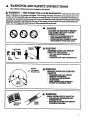
TRANSPORTING
AND
STORAGE
• Stop the unit before carrying.
* Keep the muffler away from your body.
° AIIow the engine to cool, and secure the unit be. forestoringor U-amporting in a vehicle.
, Empty the fuel tank before storing or transporting the unit. Use up fuel let_ in the carburetor by
starting the engine and lettingthe engine run until it stops.
• Store unit and fuel in an area where fuel vapors
cannot reach sparks or open flames f_vm water
heaters, electric
motorsor switches,
furnace,etc.
° Store unit so line_
cannot accidentally
cause injury. The unit can be hung by the bracket
below the engine orby drive shaft housing.
- Store the unit out of the ree_ of children.
Mix and pour fuel outdoors.
Keep away from sparks or flsmes.
Use a contsiner approved for fuel.
Do not smoke or _]]ow smoking near fuel or the
unitor whileusingthe unit,
Wipe _ aH fuel spills before starting engine.
F situa_ns
Hold the unit firmly with both hands.
. .]_eep_
flrm,_
A FUEL SAFETY
•
•
•
•
In_
theareatohe cutbeforeeachuse,Remow
objects (rocks, brokenglass, nails,
wire,stag,
oeeur whleh are not eom_d in tSis nmnu_
use care and goodj_t.
lf you need asslstanee,
eon_t
_ur
"An#hor_zed.Service Dealer or the
CUb"TOMER AS_STAN6'E
HO_,
1-800-236-6878.
L
•
EM_su_ tovibration_ _p_o_
!e_ged uH ot p_oline_
dama_ _flmflngm_ham_,_dw_m_-_p_p[e_ne_e_flaflondh_dmor_mo_mfl_
i
i _
uP. t. eo_d_
•
_effi _-to
_
vessel _
wris_
r_4
_
handtooh•eeuldeause
in oth_
II
i -
..
i_11 ..._- o
]
bloodstone
h__e_._.
eal
IIIIIII
_
.
[]
Pro- []
_ _toffi_
i/11
11 "['lilil'[I
1
I
L
,,._........
bmo
jl .......
I Illlll
A,
your
I I Illl
II
i i
, ,,,,,,,,,
,,,,,,,,,,,,,,
,,
........... ".
_
INTRODUCTION
Your Trimmer is a versatile product designed to help
you give your lawn a finished appeamnc_
Special _
*
*
.
•
•
UNPEG
B.
Include:
Centrifugal Clutch
AIl-lmsitio_ Carbgretor
Adjustable, anti.be,
cushioned Assist Handle
_-Automatlc
Trimmer
Head
18 _.Cut/lagPath
iNdUCTIONS
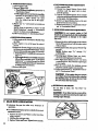
NOTE: Yourunit has been shipped with aplastic
shipping
guard over the primer bulb (see
_dpecifications"
for location).
Remove and
discard the plastic shipping guard.
hear the.fuel
rater
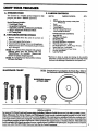
CONTENTS
KEYNO.
CAKION CO_:
o
.
Engine
DriveSha_Oear BoxAssembb'w/SafetyI._i
mxdDustCup
"
"
"
Shield
Trimmer Head
2-cycle F.agineOil
1
1
!
•.
•
Opcra_'s Mam_ (NotShown)
I.oo_ Putts!_ag(NotSho_n)
1
l
"
1. Remove contents from the carton if y_u have not
done so.
2. Check parts against Lhe list below.
3. Examine pare fordamage, Donor usedarnaged parts.
4. Noc*_ your $¢ars Store immediately ifa part is miss-
!t is n_to
CAKTON
"
;
l
,!
*LOOSE PARTSBAGCO_
Flex ShaftLube
T-_AssistHandle
I
I
HcxWnmch-.tmall..
1
.
A.
Her Wrench-Large
H_Socka HcadScr_v, ClutchShroud
1
2
B,
Slot_d
4
C.
Hex Sock_ HeadSccew. Thrc_qi¢Trigger Housing
1
D.
Square HeadScow - AssistHandle
1
E.
HexLock..Na_-C_utch
ShroudtTdg,_rH_siag
3
c.
Kb_Nm. AssistHa_le •
Largecup Washer
1
1
Hex 'He.,adScrew - Shield
*Hardveza-e
is_
in actualsi_ drawingsin the assembly
_ons.
Ccanpa_ tile haxd_e iath_lcose pans bag with the
haS,rarein_ drawingstode_imir_th¢con-ectrafttouse_
'
rathe in
aa empty fuel tank.
aDWAaE CHART
@0
A.
B.
C.
D.
E.-
E
SPEGIAL NOTICE
O.
L
For users on US. Forest land and in some s_tes, including California (Public Resonrees Codes 4442 and 4443) ,Idaho,
I_mesota,
New Jersey, Oregon, and Washlastem Certain internal combustion engines operated on forest, brush,
rod/or
grass-covered
lands, in the above areas, must be equipped with a _park arrestor, n_intained in e£Sectiwworking ord_,
_rthe engine mustbeconstructed, equipped, and maintained forthe prevention offire. Checkwlth yourstat_or local authorities
_r regulations pertaining to*these zequimments. Fai!uze to follow the.s¢requirements is a violation of 1he law. This unit. is not
hctory-equllgmdwttha sparker;
howev_,a sparkarrestoris_le
asan optionalpart,irasparker
in your area, order Pat't#952-'/01612 from your Sears Service CenleriDcpartmem.
__
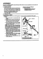
ASSEMBLY
(If tool is reeeivM, assembled,
justed for the operator.)
repeat
all steps
in this section
A. PREPARATION
I
B.ASSEMBLY
assembly
is correct
and ii ad-
z. ltead yotw Operator's _
' This Manual is designed to help you _semble the tool
and to provide its safe operation. It is important that
you read the entire manual to become familiar with
the tool before you begin a_sembly. If you have ar_v
questions or need fixrther assistance, car our
CUSTOMER ASSISTANCE HOTLINE at
!-800-235-5878.
_1] ]1
to be.sure
II
IIIIIII
I I I/
__
,
HI I
2. Toeh you willaee&
- Hex Wrench ¢avvided with the tool.
_j__
• Wx_.n_
orta_ plien
Flat Blade Screwdriver
Illllllllllllll Jill
ST_PS
Hardware referred
toin.the
following
s_."oneisshown actualsizeintheHardware Chart,page 5.
i.Tt_E
v. Place the two screws _L" into the holes on t_e
b. Posltionthe]ock-nutb"E."
in the lower holes.
c. Tighten ,scr_-,vswith the-small hex wrench (.provided) just enoug h to hold hardware together
while homing
lock-nuts
.with your other hand.
d. Remove the packing coverfrom the.straight
end of the tube(ifso equipped). Your unit may
not have a packing cover.
not fall out of the tube_ Dirt on the shaft will significantly reduce the life of the unit. If the flex_e
ddve shaft falls out of the housing, clea_ re-]u_
hricate, andi,_-re install See _Flexible Drive Shaft
Lubrication" in the Maintenance
section.
e. _the
bot_m 8r6o_ ozi"the tube With the
ridge on the lower wall ofthe engine opening.
£ Turn the shaftto alignthe'squvxeend of the
shaft wifllthe sqaure hole insidethe front
opening of the engine,
g.ra_...y_
thence_to theen_ o_..a_.
untll t_e _
ff_d
conta_
or _ wRhm
3mm (!/8") ofthe, dutch:_using.
h. Tighten screws "A.". alternately with the hex
wrench until secure.
• L.......
6
' ........
'
"!'2"2
Shaft
..........
.--
.:_
_
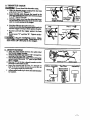
2. TtEP.OTII_
CABLE
Do not bend
a
the throttle
cable.
_de the throttle _r
housing from the foam
grip about 8 cm (1%-_eure
8.
b: _
_
csk]ethroughthe _unnet _ _e
fosm grip Until_._e endbfthe
cable e_ds
at lesst
5 =m(2")bey_l_t]_e
_p.
c. Hold.the trigS_ away from the drive,shaft housing and _
the bsn_
end of the throttle cable
into the roundopeningin _e trig_r
..
d. _
the c_le iuto the _q31itin the arm, _
•
Guide the arm into the foam _i'p tunnel:tmtilthe.
tt_ro_ tr_,erho._
grip,
£ Inste_ screw "C." andNut
at_y; .......
...
,,,,,, ,
ii a|r
......
- ............
•
_ au_h_t_'_.
_._
Tighten =_'oder.
i I/
"
s. ASSZST
lllllllllllllllll .
l
.......
II
.
I
IIIVRIOII
[I
IIIII
I
......... Assist;Handle
a, Align the,essist _e.
between the sa_'ety lebel
the _
triggerhouaipg_ ..
,, ,,
b. Drop the _ede@d._screw
D. through the
opening inthe top of the T.handle.
C, t_U on thethreaded end_ o_t_h_,ecrU. to_-ng the
_headofthescrew
D. past the pin inside
ti_e T-handIe.
"
d, Seatnut _E_iuthehex-shapedrecessi_onthe
back side of the assist ltsndle.
.
e. Insert the threaded end of screw =D._ ttu-ough the
•hote in the._assisthandle; thread the screw into nut
_F._and tighten.firmly
by hand only.
£ Ac_ust as_st handle up or downthe sha_ ho_
forcomfort.
....._'_'.
,.. Screw D.
..Safety.Label
T Handle
-7-
....
....
Tit
B. FOR LI]qE _
-
.......
Mo
o.
'
III
,m|
A WARNING
J Jl.__
_
.............................
i
..............
8. Tighten the trimmer head against the washer and dust
cup white holding the large hei wre_¢h:
9. Remove the large hex wrench.
To remove the trimmer head, inert _e la_e
hex wrenchinto the aligned holes in the dust cup and
bearinghousing, Unthr¢_tdthe Irimmexhead. Be su_
to store grass ,washer "GD, plastic shield, 4 shield
scwws_:and_hardware
with the trimmerhead lot',future
&WARNING
Failure to install
can
remdt
in
IIIII
USE
USe.
shteld:tnlthe
Iposition
shown
serious
injury to the
ope_
i
!ator. The length of the s_e|d
must be _eti
_',
with the length of the drive shaft _.
Dll
rect the widest part of shield toward the engine.i
Remove the metal shield _md blade before
• _talli_.
the plastic shield and trimmer hea_L--
L Place the shield under the bearing housing and
..........
alien_
hole_
The line ltmlter (on the unde_ide.of
the shield) is sha_
and can cut you.
2. Insert sc_,ew_ _B." through the bearing h_u_
into the shield.
3. Tighten the screws evenly and securely.
- ,.
4. Remove thepackingcover
from the arbor snar_ if so •
5. _s_gr_
washer"G." over the arbor sh_,
Make
/
sure the gra_ washor is agent and curved over the.
6. Start
the trimmer head onto the _rbor
shaf_.
7. Align the hole in the dust cup with the hole in the ccnzerfront of the bearing housing by turningthe dust cup.
Then, insc_ the Largehex wrench (provided) into the
aligned holes to keep the arborshaft from turning.
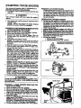
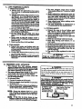
6. OPERATING
POSITION
a. Before starting the engine, stand _ showain
Figure II and check for thefoLl_
L) Lef_ arm fully extended, hand holding assist
handle.
23 Right arm slightly bent, hand holding top ban.
dle, fingerson throttle trigger.
33 Engine below wais_ level
4.) Weight
of tool evenly
dlstrflmt_l
between
5.) Without operatorbendingover, the t_mmer
headis near and parallel to the ground end easily contec_the materialto _ cut.
b. Ad_u_
the mudst handleup
or downt_edrive-
sha_ housing (but aboce the sa/_/abe2)
fortable posi_on.
_rW_ez
a__
tOa com-
the as_t bzndie -
be sure that the assist handle
remains
between
the throttle trigger housing and the safe_y label on drive ehTofg houa_
e. Rotate ezsist handle fromleft to right to tilt the
m_le of the trmmer head when.
cutt_ a lar_,
_oped arcusuch as a _t_ b_k,
.
POSITION
Arbor Shaft
"
.•
I
.........." _
I
i . Ii
i
Th_llowing a_
ununulrlrn _.
I
areav_labletJm_h _
iiiiii
II
iiiiiiii
Ill
..
i
mmlllm|lr
.........
.....................
RetailSto_e_.CatdogO_e_s. orServi_ C_t_OCK
9-1SS9
-
71.30143
Spark Plug
•
Replacement Trimmer Head (available only tliroug_ Sears Service C_te_)
............
Replacement Nylon Trinnner Line
-- 400 ft. ..............................................
. .......................
-- 200 ft. ...................................................................
-- 100 fl ......................................................................
lltl_e_m_t
Spool with Line. _,...................................................,
Sho_r
Strap Kit .........
...............................
........................
Spark _
Kit ...........................................................
•
FI_ Shaft Lube
*_b_e tJ_eu_hyour S_
Ser_ Om_r/(_tz_e.
i, nnnilllmmnmm
i E
IIII I I ill "
I-
_ ..........
" "["
_i_i
._
•
_
.
- _ "'"
_
NO,
9-18613
, ...............................................
"
2-Cyde Engine Oil
"
L_
Safety Face Shield .................................................................
Safety_
_
. ,
,
. _
.
"
_" .ll_llll[.ini aft i .
IIIIIII
"Jl
71-8$8$4
95_701643
71-8._78
:. 71._,';608
71-85771
71-K_15
71-8_/83
,. ,952-70,1612"
530-030102"
""
"
.....
I
T
NOTES
9
FUELING
BEFORE
YOUR ENGI
FUFJANG ENGINE:
A WARNING
Be sure to read _e file[ safety information in the Warnings and SmOky Instructions
section on page 4 of this
manual before you begin.
IfYou do not understand _ fuel safety section DO NOT
iattempt to fueI your unit; seek help from someone that
doe_ understand the fuel safety section or call the Customer Assistance Hofline at 1-800-235-5878.
2-CYCLE OIL:
CRAFTS1KAN 40:! 2 cycle oil is strongly recommende&
This off is specially blended with fuel stabiiizers for
increased fuel .stability (extends fuel life up to 5 times
longer) and reduced smoke.
CRAFTSMAN
quality
2 cycle
2 cycle oil is not a_le,
AIR-COOLED
Gasolinean_ oilmustbe premixedin acleanapprovedfuel
containe_ Always usefreshregularunleadedgasoline.
CRAFTSMAN 40:I 2 cyele engine oil is specially blended
with fuel stabilizers. If you do not use this Sears oil, you
can adda fuel stabilizer (_uch as Craftzman N o. 33,500) to
your fuel tan!_
I0
a
no not use_
•
AUTOMOTIVE
•
BOAT OILS
OIL
_
BIA. etc.)
GASOLINE AND OIL TURE
Mix gaso-Iine
and oilas follows:
* Consultchartforcorrect
quantities.
. Do notmix gasdline
and oildirectly
inthefueltan_
FOR ONE GALLON:
*
Pour 3.2 ounces of high quali_ 2-cycle engine off
into an empW, approved one gallon: gasoline container,
.
Add one gallon ofregular unleaded gasoline to the
gallon eon_dner,
then Securely replace the cap.
Shake the container momentarily.
•
•
The mixture is now ready for use. Fuel stabilizer
can be added at this time if desired; follow mixing
instructions
on the label.
STABILIZER
Fuel st,sb_]_er is an acceptable alternative
in ___;,_g
the form_ion
of fuel gum deposits during storage. Add
stabilizer ,to gasoline in fuel tank or storage eontainer.
Always follow the fuel mix ratio found on the _tabi]izer
container. Run engine at least 10 minutes after adding
stetdlizer to allow the stabi_.er to reach, the carburetor.
You do not have to drain the _el _
for storage ifyou are
using fuel stabilize_
has
These oils do not have proper additives iror 2-cycle,
AIR-COOLED
enginesand cancause engine damage.
IMPORTAN_
Experience indicates
that alcohol
blended lusts €_dled gasohol (or using ethanol or methanol) can attract mo'mture, which leads to oiFgas separation and forma_denofacidsduring storage. Acidic gas
can dams_e the fue! system of an en_ne while in storage_
To avoid engine problems, the fuel system should be
emptied before storage for S0 days or longer. Drain the
gas tank, then rrm the fuel out ofthe carburetor and fuel
linesby startingtheengine and lettingitrun untilit
stops.
Use fresh fuel next season.
See STORAGE
instm_ons foradditional
information.Never useengine or carburetorcleanerproductsin the fuelt_r or
permanent damage may occu_
FUEL
use e good
oil tha_
recommended fuel mix 40:1.
IMt_RTANT!
The two-cycleengineon thisproductrequiresa_el mixtare of regularunleadedgasolineand a high qualityew
gine oilforlubrication
ofthe beariugsand othermoving
parts.The correct fuel/oil
mixture is40:1 (see Fuel Mixture Chart).Too little
oil or the iueormct off type will
cause poor performanceand may cause the engine to overheat and seize,
en_me
FUEL MIXTURE CHART
40:1 Fu_l:Ofl
Mix l_tlo
1 gallon
t
3.2
L25 gal!ons
fia_zline
2.5 gallons
-i
r
11 r
4.0
Off (ft. oz,)
8.0
__
STARTING YOUR ENGINE
(For location of eentmk, refer to _S_")
BEFORE STARTING THE F24GIN_
• Fuel e_ne.
Move 10 feet (3 metres) awe_yfi'omfuelling site.
The trimmer
starts.
•
head
u/t/turn
w/te_
A WARNING
Rest engine _
end off ground.
STARTING A FLOODED ENGINE:
Flooded e.___
can be start_"l_, mo_'the
mm"i.
+t+t_
tothe"On _itienandplacingthe &+ke k_v+ m
the "_ Choke"po_i_tiom
_en, pu_+
the ro_ to _ear
the enl_
ofexcess fit+ This <_d requ+3re+
p.umng
the starter _repemany times depending on how oacuy
• the trait is flee&d.
the engine
OPERATING
INSTRUCTIONS
• Do.o,
shield on ground, supporting lower
neeeNa_.
the _
Removeand discard the Izle__icshi_
is run at less than fun tl_rottle. At l__wer
on the primer bulb (ifso equil_ed).
cu_
_.t_ot_e trigger_mdp_._the_
_
linew_ last!ongerand willbe
_elese
leselike
lyto
.
STARTING A COLD ]_GM
OB WARM ENGINE
AFrER RUNNING OUT OF
• _ Move the swlt_ to the "On" l_z3ition.
• Move the choke lever to the "F_II Choke" position{
• Slowly press the primer bulb 6 times,
• S.queez. e and hold the throttle trigger, Ke_
the
throa_
_g_er f_y _
un_ th_ _.
smooth/y.
• Pu!! starter rope sharply 5 times+
The engine rosy sound _ .if it is tryin_ to
start before the 5_pull. _Ifso, go to the next step Immediately.
• Move the choke lever to the "Half Choke" position+
• Pull the starter rope sharl:_ until tke engine runs,
but no more than 6 pulis.
.,hu not start_ after 6 pulls (at
to make sure the switch and the
choke lever are in the proper posi_ons. Then, move
the choke lever to t_e "Ftdl Choke" position and
press the primer b_b 6 times; s_jueeze and h_oldthe
to_
,oIdle
_
Whe_-o*_.
Ifthe trlmmer heed do_ not tur_ when the en
_
ts _ceelerated,
make rare the &ire _tit h ous.
•
_Assembly-Drive Shaft Houmn+g,.
To 8to_ the • +_
• Releeseth-e
_e
_
• Move the switch to the Off" position+
•+
z more
times. Mo_ the ehoke lever to HalfChoke _mdpttU
the starter rope until the engine runs, but no more
than 6 more pulis.
-
flooded+Proc_to
•
Starti_aFioo_.
_
_
Allow the _e
to run 15 seconds, then move the
choke lever to OffChoke.
AIIow the unit to rtm for
30 mo_ seconds at "Off Choke _ beferereleasing
the
throttle tr_er,
•
Switch
If engine dies with the ehoke lever at the "Off
Choke" _pogiti_, move the __pke lever to "Ha_
Choke" _
pull the rope unt9 the engine runs.
To stopthe enl_ue, move _
to the'_O/_ position.
I.... --•
+o,%,
iaW G.
L+
IAvoid any bodily contact _th
the muffler
t._gawm,
menffine+
Ahotm_ercanee_ase|
tserto_ _
when
I
|
Choke Lever
!
" !1
4.i_a warm_ilae(_n_ehunliout
enllull):
Refuelen_ne,Mow10feetawayfromfueting
site.
f. Move Chole to"off" position..
b. Move On/Off Sw_tch to "on."
c. Move Choke to"'full" position.
g. Full_
Rq_ u_e_in_
nm, lx_nomc_han
d. C,nupFrom
C,_anesqu_z_"nu,
o_'rdg_ _y.
Keep Throttle Trisger fully $_wcZed _
r!1_.
engine
NOTE: Heaginchas not staned,lmll _r
P,ag¢
5 more Falls. Ifeng_
still does hot run, it is probably flooded. Waita f_w minutes and _
procedure with L"ho_ at "off". _.
PuttSurerRopesharplyun$ engineauemp_to
run, but no more than 5 pulls.
D. oemaTmGmsnu..on..ore
1: Before entering the material to be eul, bring the
engine to cutting speed by squeezing the _e
trigger.
2. Always releasethe Throttle THgger and allow the
engine to retain te idle speed whm not cutting.
a. Do not run the engine at a hlgher,speed
than
3. Mal_ sate the _rimmer Heads_ps awning'what
thelhmllkTrigger
isreleased
and theenglne
necessary. The cul_ag line wi_ cut effieie_y
when the engine is run at less than full thn_..e.
At lower sleds there is less _no'_
and
rims al idle speed, For om'ecfion refer i_ "Ca_u-
r_torAdjusunenls:'
vibration.
The-trimmer
linewilllastloagei,,
and
will be less likely to "'weld" .ont_. the spooL:
b. If the Trinket
4. to stoptheeagiae:
Head does not luru whenthe
engineisaccelerated,make,sure
theD/ireShaft
L Release the Throttle Trigger.
b. Move On/Off Switch to the "Off'
Housingis properlyseatedinthe ¢lu_ Shn_.
. Refer to "Assembly-Driv_ SlmftHousing:'
_-.
, "ll
:.,',',',','D,,-_,,,
USING
_._1
.............
i,m I i tiif_ ,,,,m
"
YOUR
IIIII
II
Illlllll
II
I
,
,r_
_'
,
r, f
a ' .""'I"!'""!!.!!!::.-.....
position.
•
;
:i '
,:I"'I'_"!"
i
.......
Ill
:__
l
: =,
II
HI __
IHI_HHNJ
UNIT
I
IIIIIIIIIIIIIIIIIIIIIIIIIIIIIIIj
.........
]
"'111
IIII
I
AW G
II
......
i/
I
IIIIIIIIIIII
....
.......
- T OWSO JWrs
The rapicHymoving line causes objects toI_ thrownviolently.
The shied will not provide
complete protection
totheoperatot or o_rs. The operator must wear a safety fa_s_g!d
orgogg_
Alwayswear heavy, longpantsandboots.
Keep .
oUhers at leb_ 30 feet away.
tool will throw objects and cut.Keep others including
children, animals, bystanders, and helpers at least 30 feet
away from the opem_or and tool. Stop the engineifyouare
approached.
i
i1
IIIUl
11
I
I
llllllllllll i
AW_G
-- SbtMA_
l_l_m4m
iw.
Trimmer head. parts that are chipped, cracked, bmkeI1, or
._..
dan_d _any_
Trimm_Head
UseOn_y
__p_mnents_
parts be_m'eusing the tool
_-
:+
12
caneymar_an_causes_ous i_ury,
Do notuse.Throwdamagedpartsaway.Replacedantaged
,it
+
•
,
.....
U
IIIIIIIIIIIII
xJ W
I
I
......
i
I
llllllllllllllllll
III
II
a. Always
SAFETY
wear
d. Be
eye .p_te_.
_
inside
B__haust
trimmer
head
_stops
_the
engine
on the right
side
d. _,.,_/_
footing
and balance.
Do not
andfueL
e. Keep the trimmer head belowwaist
level.
f. Do not rzdze the en#ne
above your waist.
_..Keep aUp_u.tsofy_ourb_'_ oaway_m me
trimmer
II_II1111
"
|_
B. TRIMMER LINE ADVANCE
une_wm ._
...........
& WAS_
"
__
a_e_-
the en.
L
",r
"
-
. I H !I!!H
y
.....
'A wAC_
De not u_e other materials such as wire. sung. rope. etc.
Wire can break off during cutting and become a dangerous
....
_
,
it t
.
IUse ndnimum
2, .Hold the trinnner hea_ parallel to and above
me grassy are&
.
.
t_
'='
.
..7
g
]l
oa
_
w,umm
I._
I II
I
.
i
I
I
,qpeed. and do not erowd
i_ei.eute__ha,
"
"
Use only .OgO"diameter SEARS Laser Line. Other sizes of"
line will not advance properly and can cause _rious injury.,
i ......
:::
_.
when.
"'
•
.._ theb_tm ofthe_
mKd muffle_
uaL
II
z Inene_ each t/lae,the
bottmn _d_the
_er
head is tap_.,
on the g_und
With
the engine ruanmg at x_ throt_e.
• _e
mo_ el_Sete_
ltae length is the max/.
[en_
t_Owed
by the]hie ][tlatte_
• __
_e:
1. O!_atetheengtneatfi,dlthro_e.
line
It, Use only for jobs explained in this man.
use wire, st_g, ro_, etc.
e...Make sure the tlrtmmer head is property
:L_ed
and seeurely
fastened:: P_er/_3
:_Assembly."
• The _
I
c. Hold the tool _h-mly with both hands.
L _t
the _
t_JolCheck
beforeforeach
uee,
fuel lealm
andmekeN
pkceand_ecur_ _tened.
b. Use only.OSO_dhmetn-Se_s Laser Line, Never
II •
sure
Alw_
a
2. TOOL 8AFEq_
"
7
& L_FrING SAFETY
a. Impect the area to be cut before eaeh
anee.
e. Never start or ,run.the
dosed room or building.
Lfumes czn kilL
f, Keep handles free of _
'I* _
7
Hold the unit by ha_xd; do no_ use me opuonm
shoulder strap for support.
f. Keep ot]:ter_ away when making earbu.
rettor adjustments.
g. Use only aeeessories
or attachments
as
recommended
by the manufacture_.
-fray _
w_ help pt'oteet you _
piec_
of toxic p lan_ inch as pox_m ivy thrown by the
trimmer _
which could be more of a hgzard
than touching the plant itee_.
c. Do not Operate_ this unit when you are
tired, ill or under the influenee
Of aleohoI, _
or meal/cation.
d. Do not swing the tool with sueh fot_e
that you are in dang_
of lining yo_ _h_l.
bat
"
III
me_ts."
e. Make earbm_ttor
a_tjus_ents
witi_ the
lower end supported
to px'evmxt the trim-
Jo_e_othtng,or
_ewe_.@ort_.,
I
I_I.
II
when enstne idles, See"¢_d_ur_r A_._.
ion when Ol_X"at-
your uni_
b. _
wear heav_ lo_ng trousez_
boots,
and glov.es. Do not go bad'efoot or wear san.
I
I IIIIIII
SAt'E
1, OPERATOR
l[I[]l
III
ri
r
the nnel:
do_ee_(me_grav_!
lfeaee t_te.
ere), wh!eh ean dmnage_ the tt;tmmer i
" It_
|head,-bee0me
emudn_ entsnSl,
a ,_46us ed _; in th_ .line, - or be[|
I..........
_ _
_
'
t
_e
_ter
_t_
Line
,
aaph_em_uN_ee_arto_etrim.
Now_
taehm
If the line i_ worn down to two
or less, moz_ than eue trap will be re-
.A
"
quiredto obtainthe most efficim_]_ne lent_
13
+_
..............
_ ii
_._
.C. CIHTING
.y
_++iiiiiiiii_
iiiiiiiii
,,,,,,,,,,,,,,,,,,,,+!
, ,.,,
_,,r,I i....
m!! _,,,,,,,_,,,
......
_
, ,
........
_._,.,
.--.
...................
,,
,,_,,,+,+
,"''_'" ,......
,|,, ""+i "--_l_T'_
iiiiiiiii
METHODS
•
The tip of the line does the cutting. You wi_
achieve, the best perform_ce and mhfimum line
wear by not crowdb_ line into eutt_g area+ The
right end wrong ways are shown in
•
The line will easily remove grass and weeds
from _d
wtd_ feuo_b gvoes and flower
beds, but _ o2_o eun cut the tender bark of
tre_ or #h4_
and gear fenee_ To help avoid
_
to delicatevegetationor trees
• with _nderbark,
shorten line to 4-5
use at less than full throttle.
e
"='
inches and
For trimming
or sealpir, g. use less than full
throttle to increase line life and decrease heed
wear, especial:
- duringlight duty +u+mng.
near objects around "w_ch the line can wrap
such as smsllposts,treesorfencewire.
e
Ii
For mowi_
or sweeping,
good_ean job.
use full throttle
......................
4 w_G
for a
......- ........................................
I
Alwa_
wear eye. prqtecflou_
N.evor lean over the !
henri: _
or debr_ can rlooohet
orl
be gbrown int_ eyes and+ face and c_aJe bKud-|.
nessor.,_er
+se_+
ous in+my. ............
• !
L TRIMMING - Mid the bottom ofthe trimme_
heed about 3 inches above the ground and at an
at_e-
Allow
only
the
tip
of
the
Line
16
MOWING
to
make contact. Do not force the trimmer line into
the work are_
2. SCALPING -The sca]ph_ technique
removes
unwonted vegetation. Hold the bottom of the
trimmer head about 3 inches- above the ground
and at an a___ AUow tip of "line+ to strike
ground around trees, posts, monuments,
eWT_ _
it.creases _
8. MOWINGYour trimmer is ideal for mowing
in pieces conventional
lawn mowers cv_xot
reach.
In
the
mowing•position,,
ke_
the
line parallel to the ground. Avoid+pressing the
head into the ground as this can scalp the ground
and ckn._
the untt+
•
4. _PIN(g
-The fanni__ action oftherotating
' ]hm can be used for a qui_ .and easy clean up.
being swept and move the unitfromside to side,
NOTES
i
-_
+
..........
+ I
....
il
II
iiiiii
_'Z."_r'-
D.LINE
•
_+
i_mm
"
_
Ii
+
II _
I
1 lilt
I
REPLACEMENT
For proper line fee_
- Use only genuine Sea_ pre-wound spools and
.!180" diameter Sears Laser Line brand line.
Use of o_cr types of spools or lines can result
in excessive bw_ge,
i_ weldi.g and improper
line feed.
- Pre-wound
spools offer the most convert.
lent method for replacing
line as well as
optimum performance.
--dd .pooland
:+
le
perfm_m_ _ type m_.
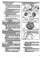
Installing
Spool with Line
a+ HoId the trimmer head M shownin
Press the lock tab and turn the loc_ ri_
shown in
as
b. Remove the lock ring, tap button_ and spool
c. Clean dirt and debris from all parts,
::
_..
............A w.ct,_o .........
:
"
llllllmlllllllml
.....
!
[i WI i
lllTT
iiiii
Catch
head part+that are ,_lipped, emmked+t
Lock Tab
or damge+. _- .anyoth_erway eaffi__!
i adam. _
cause _*lOUl _
uo not use+ _!
Ipl_
__
befo_ using.the
tooL
+ .................
!
NOTE." The aluminum line saver canbecome
during use. b_er a groove is worn
into the line saver, remove it _rom the
_er
_
t,J_n-it upside down, and .reinstall it (with the spool removed) to-pro_de a
new wear surface.
I+L ......
,,_w,mm.mmG
I
liue_vermu.m;belustaRedoulyfeomthe
_.1
e of the trimmer head+ Ill]retailed
on the out- I
of the trimmer head, the line saver can flyl
._
_e.
I .,+
e. Insertthe end oft_ liue_
the tine saver.
Place the spool_in trimmer head.
Pr_ess the
spool do_
then mrn it enough tolo_
the lu_ .on tile
drive gear.
t_e _
spool under the lugs on the
et SlX_l and the wall of trinnn_
hes,_
over _e tames onthe hub; push the lock _
downon the hub and turnit clockwise un_ the
_n_hes lock_to pb_e,
I •
I
.I.--_U_
mmrt be ful_med
llatehedL tu the Ixmk Ring.
Ireet_
the .L_.Ring
eant_
......
• _ ___
and the lock tab,[
It'+_talled
tueor.[
off aud become
al
sun) the 1_
on_
+.......
L Obtain t_ecorrect line length (4-6 inches) by
pressing the tap button (Figure.22) and pulZ-
_.
ing on theline _.
Es_. time the tap buttonis p_ssed,
!
2. Spool Replacement
___.-
If' tt comes ot_ renlnst_
_
h. Pull on the .linetoy.haremthe spool from the
lockedpositionto me _
!m,ai_on:.
o
k_ o_ are_
b. T_o_
__fo_t_
o!_reducedinmze,orbro-
_m
3. installing
,,,,i Ill
I
Line on Spool
To replace
the Line on existing
I
........................
Spook
Fellow "Installing Spool w/Line,"Ste_
"a.-d." and remove any line remaining on
the spot.
b,
Usea4Ofoot_
Line.
Inert
o_J{)gOmdialtle_r_.._t_La_F
Lug
1/16 _ to 1/8" of"the end of the line
WORN
tb_ugb the hole in the q_l.
Allow no more then 1/8" line to extend in.
side the spool.
d. Wrap the line onto the spool firmly and
evenly in the direction ehown by the arrow
on the _I.
NgZ[_
The line must be wrapped firmly end_
eveuly for proper li_e fee_
e, Follow "InstaEingSpool with Lin_" steps
.............. SPOOL
....
..
"
iiiiiii llll_
:
.
.i
/ ii .
For best results, use only ,_80"
_ If the line b_
offor bae3ks up inthe trim.
met head, follow "Installing Spool w/Li-e, _
steps _s.-dZ Pulls]a_in
line untilthe line.is
tightly wound on the spool, le_.ng 4-6 in_es
of ext_ded line. Continue with steps "e,-L"
m
i
.......
4. Trouble
•
-
Does
Shooting
not
the
adwm_e
Trimmer
or b_
Head
while
iiiiiiiiiiiiiiiiii
iiiii
i .
I'i
cut-
• WeI_
ttu_
e
.
. USTOMER
"
.
UIIU
onto spo_
- Line size incorrect.
- Improperly wound onto spool.
- Line size incorrect.
- Too little line otttside head.
Pulls back into bee&
- Too little line outside of head.
.........................
iiiiiiiiiiiiiiiiiiiiiiiiii
iii
ii
and Line
- Incorrect spool
- _
line egainst materiat being cut.
- Cuttingat higher speedsthan necessa_.
IIIll
I
W[1[
mill
I I
I III
I
II
I
I
II
RESPONSIBH,ITIES
MAINTENANCE SAFETY
1. Mai_ain
unit according
to recommended
proeedu__.s. Keep cutting Rue at proper length.
•2. Disconnect
spark plug beforeperforming
maintenance
except carburetor adjustments.
3, Mak_ c_rburetor
adjustments
with drive
,shaft ho_using SUpl_rted
to prevent
the
trimmer-fine
From contacting
any object.
4, Keep others away when making
carburetor
v_dstments,
the uni_
II
..........
chipped
or damaged
I [
MII
_
I
before
II
III
. -
using
II
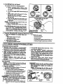
A dirty air filter decreases the life. and
performance of the engine and may increase fuel
c0nsumption and harmful emissions. ,
I. Clean the Air Filter:
• Always after 6 tanks of fuel or 6 hours of
operation,
whichever
is less.
" e, More frequently; in dusty conditions.
a, .Loosenthe two screwson the airfilter cover
enou_ to remove the cover- from engine.
b. Remove the air filter from the cover.
c. W_h flIter in soap and water.
d, Squeeze Filter dry .v_d replace in cover.
DO not _
the air falter In ffasoother
ammable
solvent; doing
so may create
a fire hazard
or produce
• harmful evaporative
emissions,
16
Reinstall the air filter cover, making sure
•the choke exit dot is placed over the choke
6. Useo.ly_S0"diameterSearsLaserLke
.N_,,
usewir_ __1_,_xin_,._c.
7. Use only ffenume
.SEI_P_S"replaoemen_
parts. Use ot"other brands ofreplac_ment pexts
can ease _d_mageto y0_ Unit_ _L_y tot_e oI_
erator or others, Ydur warrauty does not cover
danmge or liab_H_causedby tl_e
use ofaccesso.
ries end/or attachments not sp_eificalIy recommended by SEARS.
8, _ct
the entire
unit. Replace damaged
par_.Check forfuel leaks and make sure all fas_ners areinplace and securely
fastened.
Ill
II
IIIIIII,. .
Make
°•
II
I
I llJll ,
sure the air filter is fitted
of the eover to keep dust
the engine and eav_ing en-
from entering
gine damage.
NOTE-. If repla_ng
the air filter, _
the
Accessory List for proper part number,
Air Filter
Cover
Corners
........
•
iiiiiilii
i
Ili
I
iii1"_
-
__
i
iiii1_11_"11
1"
•
i
.....
H.
i
-
nnviii |1 nnl
•
inn
IIIIII
.....................
_1
JJ,,,iiiii i
.
ii J
t
A_
_
.;
........
.
r
sc:g,l_l¢_t
._
_W_
Do aot remo,_e tl)erelaini_
tab mK! _
to x'emov_
puUey.
'huespringbeneath
_ pu_eyisundertemion
audcaunyout caustugserlous
iu,lur_.UauyparteRhe
_mUeytmus_assm_damageaother
am-_rope,
donotusethetool _ittoyour
SearsServ_ Ceater.
I.
Di_.,onaect Slm-'I¢Plug Wke.
2.
Remov_ tl_ __:and
from
Nut int!m _
Tdgged
Drive Shaft Housing and _
ThrOttle
c_Ie from_.
_-c_.,gl_leout of Biamo_
t).tmael.
3. Removethe fourClutchShroudScrews_
the.small
hexwrench
p_",,iced.
4. _the
O_
_x_
from_Engir,e.
I)rt_) .,.€Im,e_
e,_-d_U,:.
5. Hold tl_ "Flats" of the Clutch with an adju_te
wrench and remove the Nut cotmtetelockwise with
a 9_6" socketwrench.
au_ wiU_de
off
_ c=aksh_
in_t.
r_ di,m_erable
.
clutch.
Removethe.l_led Washer,Clutch, and LargeFlat
%hsher as shoma in
7. Remowthe Pulle_ Housing fromti_.
8. Remcwe Rope l_ten_i_n Screw. Remow any remaining rope.
9_ Hold Pall_y Homing andhand mm thePulley dock-
wis_ as far as it wi!lgo. Them,mm thcPulleycounterclockwise tm_ th_ Pulley Notch is aligned with the
Housing Nol_ next_ the Retaining'_b andScrew.
Next, mm thel_alleyoaeaanpletemm
counterdm.kwise untiltl_ notch_s are aligaed again.
" 10. Insert the small he,
xw_nch intothe holeformedby
the Notches to hold the Pulley in position.
H. Usea42
12. Mov_av_
meatRol_
#length of rep_eatt
Rope.
00f_) fmmtim fud tin& wi_htt_ replace
Usea mamhandmeltboth ends of_eRope
17
13. Pullthemeltedendstli_jgh a thick, dean ragwhile " "
the I_pe is stiff hot to obtain smooth, pointedends.
14., insert one end of the Rope _
so.re witha kn_
the Handle and
15. Insert the other end of the P,_pe throu_ the Pope Exit
,Hole, intothcinsideoftl_Hottsing_
int_thePtdl_y,
and up through the I_._ey Hole. See Inset,
t_ WrapR,_ cotm_eloek-wise ar_tmdthe Pdt_ Rat_t
and tuck loose end under Rope wl-_re it c_mes out of
the Pu_ey Hole, Leavea I-inch udllayingflat 0ntop_
the Pt_ey between__P,
tion ScrewfPost.
ib and_ Rope_
17. Reinstall _e Rope Retention Screw into the r_tew
tion post. Tighten until snug.
NOTE: Do not overagh_n the Screw. O_rt_teaing the screw can cause flaethreads in the screw post
to strip out.
18. Hold Pope taut at Pope Exit Hole so it will not move
•and remove hex wrench.
t9 Slowly feed rope into the Pulley Housing.
2(1. Make saw Spacer is in place then reverse steps to
Whenreinaan_ thedutda,tighten
the nut just until the beveled washer is flattened
against the dutch. Over or tmdertighteni_
the nut
can came engine damage.
II
I....
""
D.
_LE
•
.
*
....................
'
DRIVE
Lubrieate
.
SHAFT
the lqe:n'ble
i
I
,r ....
ii
[11111;1111
"
i_1
_
ii
I
iiiiiiiiiiiiiiiiiiiiii1_1111
_
11
Drive
Shaft:
,_
dean
.............. •
Lay the fle_ble
surface. Avoid laving
floo_ ground
"
i
ii _"
iiiii
.....
"
.11_
.
IIIIIIIIIJhJ[..J .........
I
]
,
i
.......8...Remo_e-the, flexJble:dadvec_aft frem-thetube,
4. Cl_eckflexible
driveshs_ forbroken wires,
twistsorkinks, and replaceff demege is found.
5. Using a denn cloth, wipe surface o_ flex_le ....
drive shaft thoroughly to remove any grease.
6. Apply a uniform coat of lube to the entire surface of the fle_'ble drive sha_.
enginehas_us_t
b_en o]_erated , avmd toue.l_mg ]
r_ue murtJe_ _x .oz mul_er
can emme Sertousl
_
iiili_'ll
LUBRIr_rlON
- After each ten (10) hours of operation.
- Before
operating
ff the toot has been
stored fo_ 90 days or longer.
When ord_
flex shaft
lube, see the
Accessory
List for proper part number.
burn&
I
""
,
7, I_ect there'_maiging
contentsoft_etube into
the top ofthe tube.
8. Replace flexlq_le drive shaft in the tube.
,..... _]
drive.shaft
on a
the shaft on the
or on. any other _
pat
9. Reassemble the gear box to the robe. Tighten
may ha_ dirtor debt'_-.
Evena_y wiping
......screws
S_zely.
....................
: ....
.....
Ute
st_'r, that
_gresse
ean pickor Up
dirt
par_ot.es
can residue
cause _lamage
prema.
[
T_ke eare.l_
avoid
tnj _u_ to ygur
__
,_.
_ Gear Box
i
...
hsnds and fingers wit_ broken wireswhen
checki__
for damage or wapmg the flexible
drive shaft. A cloth will not prevent broken
wir romp,meturingortear yourskin, t
Re o othe
eatingscrew from the gear-bo_-
the
2, Remove the gear box from the tube.
18
."
[
,
,,|
.... -......... t
L oumm_tt
Anjl__
• Tht_is a co_
task. It is im_t
instructions in sequence as indicated.
2. BASIC CARBImETOR
to follow
NOTE: In most cases, your _gine can be made to
mn Wot_ly
with minor carb_r
adj_ent_.
Refer to "_muble Shooting Suggestions" in the left
column for the condition you axe expe_ienci_ and
follow the L_tmcti0ns. The basic carburetor settings
AWARNING
Make carburetor adjt_s'_anents wi_ the drive shaft
housing supported to prevent the trimmer _
from
contacting any object, Hold the tool with your hand;
do not use the _
shoulder strap for support.
Keep others
_idjustments.
away
when
making
&wAumo
carburetor
SEtTInGS
areprovidedincase_y a_ required.
"
a. Tam the Low Speed Mixture Screwand the High
Speed Mixture Screm clockwise until they stop.
Do nottarn thescrews umil they are aght as danutge
to the needle seats can occur.
b. Tarathe Low Speed _
and High SpeedMixture Screws one full mrn countoreloel_se.
• l_r engine performance can be a result of other
causes such as dirty air"f'dter, carbon build-up
on muffler outlets, etc. See "Trouble Shooting
Chart"
before
proceeding
with carburetor
c. Fol!ow instructions "a. Preparation" through "f.
High Speed,Mixture Adj_nt:'
3.PR0CEDURE
a. PREPARATION
•
• The carburetor has been carefully _
at fl_e
factory. However, the operator must be _
that
adjustnients are made when any of the conditions
eccur as mentioned in "Troulde Sheeting Suggestions" below.
• Y_ry small adjustments can affect engine perf6rmauce. It is important to turn the screw a verysmall
amount per.adjustmefit and test performan.c_e before
makingguttheradjustments.
Each adjustment
should
be no more than the width of the slot in the adjusting
SCOWS.
L TROUBLE
SHOOTING
SUGGESTIONS
°
-- Engine will not continue to run at idle posltiolt.
See "bY Idle Speed Adjustment" and "e. Low
Speed Mixture Adjustment"
-- TrimmerHead centinuestospin whentheengine
idles, See "ix Idle Speed Adjustment" and "d.
Deceleration Check:
Lt
*
"
l.)Useafreshfuelnux.
See Fueling
YourE_.
v'_
2.)Make sum the tine extends tothe length atlowed
by the line limiter to provide correct load on
engine.
3.)Stm the engir,e. Cut gross for3 minutes to warm
engine. The engine must be at operaang temperature before carburetor adjustraems w.n be per-
formedcorrectly
4,)Stop engine and rerno_ air filter by pulling it out/
wifl_your fingers. Refer to "Specifieatiom" for, ....
location,
.::
_ mLZSn_.DJU_
L)Allow engine to idle:
2.)Adjust Idle Speed Screw until the engine
continues to run without stalling and Without
the trimmer head moving.
-- Engine diesorhesiUttes when itshouldaccele-a_
See "c. Acceleration Cheek."
-- Turnscrewclockwiservincrenseenginespeed
if the engine stalls or dies.
-- Lossof cuttingpowerwhichcannotbeco_
-- Turns¢.mwcountemloctm_ise to slow engine
down and/or to keep trimmer head from
turm'ng.
_ d,mi_the_r, lt_.See"f.m__mixture AdjmtmentY
• -- Engine does not return to idle from full throttle
within 2 semmds. See "d. Decelexalion Check:
--Engine wal not run. See "TroubleShoot_
Onwt." _,
iftbecarburetorrequlresadjt_tme_ _with'2.
_k Carburetor
senin_ "
'
.
dLWARNIMG
The trimmer hne will be spinning during most of'this
procedur_ Wear your pmtectiveequipment and observe
3.)Follow instructions in "c. Acceleration Check"
and "d. Deceleration Check:'
4.)No further adjustments
are n¢cessa_ if the
trimmer head does not turn at idlespeed and
If perfo_
is satisfa_ry.
_kWARNING
•Recheckidle speed after eachadjustment.
"l'netrimmer
headmnst not turn atidlespeed toavoid _riousinjury
to the operator and other.
€.ACCELERATION
CHECK
€. LOWSP£EDMIXTLrKEADJUSlaV/J_T
l.)Allow e_.gine to idle.
l.)Allow engine to idle.
2-)_dmtl_ Low Speed Mixture Screw skr,vly
clockwise tmtil the speed starts to drop.
Note this position.
3,yTum the Low Speed MixtureScrew counter-
2.)Squ_ T_iggex
fully
a. If_is_,pmce_
to'_.
Denigration Check;'
b. If the engine does not accelerate smoothly,
,_
turn tl_ Low Speed Mixttlte Set_W counter
clockwise a
small amount (no more
untiithespeedinmcasesand_a starts
-to drop again. Notethis position.
4.)Set the Low Speed Mixture Screwat the midpoint between the two positions.
5.)Follow instructions in "c, Acceleration Check"
and "d. Deceleration
Cheek.*'
than the width of the slot in the adjusting screw.
3.)Relxat step "2.)"until smooth acceleration is
obtained.
NOTE: It may be necessary to repeat "b. Idle
Speed Adj_tment'" through '_c. Accet_'ation
Cheek:' to obtain correct adjustments.
4.)FoIlowinstructions in "d, Deceleration Check:'
f. mGH SPEED MIX_
ADJUSTMENT
IcAtrnoN:l
Do not operate engine at full
tlu-ottle for prolonged periods while makinghigh
speed adjuslmentsas damage to the engine
d.DECELERA_ION
CHECK
1.)Allow engine to idle, then squeezeThrottleTrigget fully,
2,)Allow engine to run at full speed for about 1
second,
3. )Release the Throttle Trigger to the idle position
and listen to the deeelexation ofthe engine, It must
,return to idle _y'and
within I to2 seeonds.
¢altl Ot'_'llr.
1,)Support the drive shaft housing so the trimmer
fine is offthe ground and will not make contact
with awy object.
2. )Allow engine toidle, Lhensqueeze Throttle Trig-
get fully.
NOTF_ Pedorm steps "3.y'
at full throttle.
a. If performance is satisfactory,proceed to
through
"5.);"
3,)'IhmHighSpeed _
Screw very slowly
clockwise uatil engine speedis fenced,
4.)Turn High Speed Mixture Screw veryslowly
counterclockwise, Stop when the engine begins
step "4.)"
b. lfthe enginesiowly or erratically retuD__ to
idle or idleserrafieaay, repeat"b, Idle Speed,
Adjustment" orcontinuethrough Low Speed
to runroughly.
•Mixtureandl4aghSpeedMixtureAdjtmments
5.)Turn the screw slowly the miaimum amount ,
dockwi_se
until
theengine runs smoothly.
6.)Follow instrucfiomin "c. Aoeeleration Cheek"
and "d. Deceleration Check:'
to obtain proper deceleration_
4.)Recheek idle speed.
["_OZ¢:i
If the engine does.not operate :_
aomrding totheselmtructiom after _ting
theadjusting steps,do_mtusethetool._E[ke
it to _ur Sears _rviee _mer,
t. mm_rAtz, _
Be sure filter
instructions.
rma_
is clean,
See
'Air Filter"
for
ICAUI_ON: ] Fit air filter intothe corners o!'the
_to
keepdkt_ma enterlng
tlmengin"
eand
--
--_
E
i
"""'-
GEAR
:
.... "
-"'
I
•
Ii1111 II
" ["
I'1
I
'
BOX LUBRICATION
• Lubricate the gear _lx after eveR
operation.
50 hours of
• Use Lithium based gear grease asailable fr1_mmost
automotive stores.
I. Remove the Screw and Washer on the Gear Box
using.a,
wrench.
2. F_:Gear Box with gear lube.
3, l_tace WasherkndScrew.TtghteaSctewsecurely.
2O
7 =
Iii
i
_111111
=11 I
I
llJ
.......
i
i
_ .----
, ".', .........
......................................................
STORAGE "; ........................................................
I
.....
:
:.
II
II
II
I
.=_,1
...................
i
i
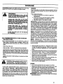
Immediately prepare your unit for storage at the end of the
season or if it will not be used for 30 days or more,
wARNING- ..... '
....
ALLOWTHE ENGINE TO COOL, AND SECURE THE UNIT BEFORE STORING OR
TRANSPORTING IT IN A VEHICLE.
STORE UNIT AND FUEL IN AN AREA
WHERE FUEL VAPORS CANNOT REACH
SPARKS OR OPEN FLAMES FROM WATiER HEATERS, ELECTRIC •MOTORS OR
SWITCHES, FURNACES, ETC.
STORE UNff WII_H ALL GUARDS IN
PLACE. POSITION SO THAT ANY SHARP
OBJECT SUCH AS BLADES CANNOT
ACCIDENTLY CAUSE INJURY TO PASSERS BY.
STORE THE UNIT OUT OF THE REACH
OF CHILDREN.
GAS TRIMMER/BRUSHCUTTER
INSTRUCTIONS
STORAGE
f your trimmer/brushoutter is to be stored for a period of
time, clean it thoroughly prior to storage. Remove any
• dirt, sawdust, leaves, oil, grease, etc. Store in a clean dry
I
IIIII]111111111
II
IIIIIIII
I
--
.
.
:
,1...............
ENGINE
Never use engine or carburetor cleaner productsin the fuel
tank or permanent damage may occur to fuel system components.
Follow these instructions:
a. Drain the fuel from the unit into an approved
fuel container.
b. Drain the fuel lines _
carburetor t)y starting
the engine and letting it run unti'tit stops.
c. Allow the engine to coo] before storage.
IMPORTANT: It is important to prevent gum deposits from
forming in essential fuel system parts such as the carburetor, fuel filter, fuel line or tank during storage. Also, experien_. indicates that alcohol blended fuels, those that use
ethanol or methanol (called gasohol or oxygenated fuel),
can attract moisture and form acidic gas which will damage
your engine. To avoid engine problems, the fuel system
should be emptied before storage of 30 days or longer.
Fuel stabgizer is an acceptable artemative in minimizing the formation of fuel gum deposits during storage.
Add stabilizer to the gasoline in the fuel tank or fuel storage
container. Akvays followthe mix instructionsfound onstabilizer container. Run engine at least 5 minutes after adding
stabir_.erto allow the stabilizer to reach the carburetor.
Craftsman 40:1 2-cycle engine oil is:specially
blended with fuel stabilizers. If you do not use this SEARS
oil, you can add a fuel stabilizer (such as Craftsman #33500)
to your fuel tank.
area.
e
o
Clean the entire unit.
Clean air filter. Refer to =Customer Responsibilities".
Open the line head assembly and c4eanany dirt, grass or
debris that has collected. Inspect the cutting line, if old
(chalky-look and stickyto the touch), remove and dLscard. Install fresh new line the next time productIs to be
used.
. Lightly oil extem;d metal surfaces to prevent rust from
forming;
ii ,
-_
....... _
• _
,
" ,
_, ........
,,
handling blade; The blade is sharp and
CAUTION: Wear protective gloves when t =
can out you even when it...l....s..n
.o.tmovinq.
If your un'rtis equipped with a blade, remove it horn the
unit. Refer to "Assemb|y". Appiy a coating of oil to the
entire surface of the blade and-wi'ap it in heavy paper,
cloth, or plastic. Also applya light-coatof oflto gear hous!ng threads, then tighten blade nut securely for storage,
Reassemble all loose parts, being, surethat al!:hanoqes
• and guards are in placeand are securely fastened. Re.lace any damaged parts.
Remove spark p_ugand pour I teaspoon of 40:1 oil mix
through the spark plug opening. Slowly pull the starter
rope 8 to 10 times to distn'bute oil to inner enginesu_'faces.
°. Replace spark plug with a new one of the recommended
type and heat range. Refer to =Product Specificatior_s".
o Clean air filter. Refer to "Customer Responsibilities'.
• Reinstall all covers and hardware removed for access;
tighten all screws and fasteners.
• Check entire unit for loose screws, nuts, and bolts. Replace any damaged, broken., or worn parts.
• Usefreshfueihavingthepropergasolinetooilratioatthe
beginning of the next season.
OTHER
°
-
Do not store gasoline from one season to another.
Replsceyourgasoline can ifyour can sta_sto rust. Rust
and/or dirt in your fuel system will cause problems.
• Store your unit in a well.ventilated area and covered, if
possible, to prevent dust and dirtaccurnuta_on. Do not
cover with plastic. Plastic cannot breathe and wilt induce
condensation and eventual rust or conosion:
IMPQ.RTANT_ Never cover unit while engine and exhaust
areas are still warm.
.2[
II
I Jill
......
:
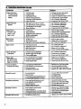
G. TROUBLE
I
J,T,,I,I
T
SHOOTING
IIIIIIIIIIIIIIIIIIIII
II
III
III
/IWIIII .
I
I
II
I
I
II1 IlJll II 11
_
_
...............
CHAKT
...._'="lllllllll
SYMPTOM
CAUSE
, l
REMEDY
_ts_
................
_
_
lli_
1
_
..................
,,,,,,,,,,,,,,,,,,,,,,
............
_._
]. Fueltar_empty
• or will ran oaly for
"afew seconds atter
1.
2.
3.
4.
5.
2. Engi_flooded.
3. Spark plug not faing.
starting
4. Fadnotreachinge.a_t_tor.
5. Cartmrgtor _adjusm_nt.
None ofthe above,
'
:-. :
Eagiae will not idle
properly
,,,,,,,,,,,,,,,,,
,,
1.
2.
3.
4.
F.agia¢ will not
accelerate, lacks
6. ContactyourSears$erv_ C_nter.
,. i i i
Idle speed set too fast or too slow.
Low speed mixturere,quires adjusm,.ent.
Throttle triggersct=w too fight.
N'o_ ofthe ahoy.
I
_1111
loll
IIIII
I
IIII
HIIIIH
III
II
•
I
t.
2.
3.
4.
2. Sparkplug fouled.
power,or dies
.undera load
3. Carburetorrequiresadjustmeta.
4. Muffler outletsplugged.
5. None of the above.
I. Clean or replace air filter.
fuel
mixture.
2. Refud with correct
See "CarburetorA@hqments:"
L Fuel mixturein_rrect_
2. Highs_ mixtu_settoolow(lean),
3. Sparkplug
incorre_,
4. None of the above.
I. See "Fueling Yo_ Unit:'
2, See "Carburetor AdjmunentsY
3. Replace with correct plug.
4. C0ntactyour Sears Service Center. _
Trimmer head mms
I. Carbaretor requitesadjustment.
atidlespeed
2. Thr_e trigs.e:screwtoo fight.
I. See "Cadmretor AdjusanentsY
2. Loose.n screw to free trigger.
3. Contact your Sears Service Center.
excessively
Engine rims hot
3.
au_ _,-_ repair.
1. Drive shaft brokenor not engaged.
stops
_a
Ioador
I does not turnwhen
engineisaccelerat_l
2. Carburaor require_djustments.
3. _utch nglui_ repah-.
T
-i,
i
Line w_lds on spool
Li__releasescontinuousiy
Lineusage is excessive
:
1.
2.
3.
4.
Line pulls back into head
'qWIJllm
Illlll
Line s'o__incorrect.
Incorrect spool.
Crowdinglineagainst material being cut:
Cutting at higher speed than necessary.
L Lineimproperly muted in head.
Linesize incorrect.
3. Cutting
athighspeed aroundhardobjects.
Crowding line against _
1. Too little line outside of head
I. Remove cover.Check line
muting.
2. Rewindline
tightly
andevenly.
®
3. Useonly.080"SearsLasetIAne
•
4. Remove cover. Pall 6" oftine tooutsid_.
I
L Line wound beyond notches on spool.
2. Line improperly roul_ hi head,
3. Line size incorrect.
4. Shield ill.lied.imProperly.
,4.
1. P,_ace or see '_tssembly:'
2. See "Carburelvr Adjus_entsY
3. Contact your Sears Service Center.
rl
Line improperlyrouted in lIead.
Line improperly wound onto spool.
Line size incorrect.
Too little line outside head.
, Illlllllll
1:
2.
3.
4.
i i ml
;
r
Trimmer5¢ad
does notadvance
or bnml:swhile cutting
.....
I. Clean orreplace airfilter,
2. Clean or replace sparkplugand r_gap,
3. See "CarburetorAdjustmeatsY
4. ContactyourSearsServiceCenter.
5. Contactyour SearsServiceCcat_r.
1, Air filter dirty.
2. Fuel mL_reincorrect.
Enginesmokes
22
,See "Carburetor Adjustments."
See "Carbur_or Adjustmcats:'
Loosenscrewtofr_tngge¢,
Coatact your se_ service Ce,ntes-
Illllll'llll
..................
Air m_r_y.
2,
FOl tankwith correct furl mixture,
See "StartingImmzctions:'
Install new plug/check igaidon system.
Clean fuel filter; inspectfuelline.
See "CarburetorAdjus_ats:'
being cut.
1.
Useoniy .080" Sears l.aser IAne®. "
2. Use properspool.
3. Cut withtipofline.
4. _Reducecutting sp_..,.,
1. Rewind line tightly and evenly,
2. Remo_ cover. Check line muting.
3. Use only J380;"Sears laser Linee.
Reinstall shield properly.
1. Remove cover. Check line muting.
2. Use only .080" Sears LaserLine®.
3. Redt_ spe_ aroundhardobjects.
4.
4. Cutwithtipofline.
R_ov¢ cover. Pall
6" of line _ oatsk_.
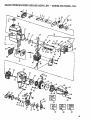
SEARS WEEDWACKER® REPAIR PARTS LIST - MODEL 358.799260-32cc
1
6
16
3738
45
64
63
Kit
i
X
7
63
91
75
l.Kit " ,l
\
\
85
\
86
87
_23
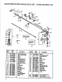
SEARS WEEDWACKER ®REPAIR PARTS LIST - MODEL 358.799260-32cc
2O
27
14
,36
•
33
8
NO.
1
2
3
4
5
No;
53o-o27549
_3o-094694
STD541025
,530-010958
530,0g?._8
71-85807
•
7
• 530-069252
53o-069266,
lO
11
12
13
1415
16
17
18
19
20
21
24
STD611005
530-094570
530-015653
530-094689
680-000139
680-093896
680-09_98
'
_0 -840007
r,OO.-_o4r=85
Description
Throttle Cable Ass'y.
Drive
Shalt
Housing
Nut
Handle
S=e_
Cuu_.g
He__
Drive
Shaft
Grip
"T"Handle"
A_'y.
Shidd Kit_.
(Ind. #_o,ll & 12)
s=_w
-_ Line Limg_
Lockout
Du_ Cup
Slm_ Lubrication
Hub_,°y
Line Saver
Key
No.
22
23
24
26
26
27
28
29
_0
3!
32
34
35
36
87
38
Part
_.No,
Descrlptlon.
_80-015774 ...........
Screw
580-010959
.T'aro_de ]LeverAr_'y.
(In_ _e22 & 24)
53..0-015768
68O'O9464O
530_-_09_t6
_zw
530-094612
630--01_28
630-001642530-001711
530-031111
He_Wxeneh. (_/_2)
530-031098
He_Wren_
(s/_6).
530 -328929
5,.-_0-095121
71-85787
530-401183
520-844102
Spring Oap
Me Ge_
580-08_27
&30-094568
580-01_5775
GearBox_,_'_
101
_30-02_159
i02 • _0-02S76_
103
530-O29764
'
Co_r
D_-Sh_Wam_
D_-S_Jd
De_-Anti-V_eHandle
SEARS WEEDWACKER®
Key
No.
Part
No.
1
2
53O-O15773
530-027529
3
5
6
7
8
9
10
11
12
13
14
530-027530
5_0-015849
530-015852
530-015254
530-027526
530-037950
530-O69247
530-014362
530 -035349
f 530-019156
530--014347
530-047096
15
16
17
18
t 550-019154
530-027593
530-027594
530 -014015
REPAIR PARTS LIST - MODEL 358.799260-32cc
Key
Description
...............
No:.....
_few
Air Filter Cover
Air Filter
Screw
Spacer
Wave Washer
Choke Shutter
Air Filter Plate
Fue! Line Fit
Fuel Pick-up A_ss'y.
Carburetor
Carburetor Gasket
Fue! CapAss'y. ,
Shroud & _
Ass y.
(Incl.#9,10
& 13)
Crankcase/Shmud
Gasket
Reed
Reed Stop
Crankcase/_
Asey.
(Inc_
_o_ps _ 66)
19
530-010960
Connecting
Rod Ass?.
20
21
22
530-015789
530-010934
530-015126
Cranksh_Retaining
Ring
25
26
27
28
530--015772
530-015780
530--027546
530-O27547
550-015771
530-014016
(_cL_)
Crankshaft,AsCy.
Flywheel Key
Screw
Screw
Switch Insulator
Lead Wir_
Screw
Crankcase Ass'y.
_d.#36-39)
29
30
31
32
33
34
35
530-027545
530--027543
STD610603
530-015162
530-025875
t 550-019178
530-069275'
36
37
38
39
40
41
42
43
44
45
46
47
48
530"032103
530-015787
530--019158
530-032102"
530--069232
530-015777
530-027523
530-069257
530-O364O9
530-016080
530--039134
530-015128
530-012235
p_
Switch Ramp
S_tch Spring Asgy.
Screw
Piston Pin Retainer
Piston Ring
•Cylinder Gasket
Piston Kit
(Incl. #32,33, & pin)
" Inner Bear_
Retaining Ring
Cnmkshaft Se_
.Bearing Outer "
Rope Kit
Screw
Retainer
Muffler Kit
Muffler Attachment Spring
Screw
Ignition Module KitScrew
Cylinder
..........
,
'
:
Description
I%.......
_;ark Plug
Locknut
PlywheelAss'y.
Washer
Fan Housing
Starter Pulley Kit
(Ind.@45)
Starter
Spring
S'mrter
Handle
Pulley Housing Ass'y.
CI_
Washer
Clu_h Ass'_.KitClutc_h
Housing
Screw
49
50
51
52
53
54
71-85854
530-015768
530-039136
530-347987
530-027517
53O-069291
55
56
57
58
59
6O
61
62
63
64
65
66
67
68
69
70
71
72
73
74
75
76
77
530-(}29395
530-027569
530-010961
530 -094189
530-069254
530-010964
530-015767
530-027511
530-015770
530-015769
530-015496
530-015788
530-015796
STD541137
530-035164
530-035166
530-035178
530-035106
530-.035188
530-035031
530-O35028
530-035014
530-O35151
78
79
80
8I
82
83
84
85
530-035147
530-035036
530-035142
530-035141
530-035023
530-035208
53O-O352O3
530-035260
86
530-035185
Carb,
GasketJD_phragm
87
530-069276
88
89
90
91
92
93
530-015239
530-015717
530-027781
952-701612
530-037972
530-016085
Engine Gasket Kit
(tIndicates
C_ntents)
Screw
Screw
ldu_ler Guard
Spark Arrestor Kit
Bulb Ass'y.
Screw
Spacer
Screw
S_w
*+
*+
+
+
+
+
+
-
Screw
Spac_
Washer
Nut
Pump Gasket
Pump Diaphragm
Inlet Screen
Inlet Needle Valve
Metering Lever Spring
Metering Lever
MetertugPin
*+ Metering
*+ M_
Diaphragm
Diaphragm
Gasket
*+ Circuit Plate
Gasket
1_ Speed Needle _
Hi Speed Needle
Idle Needle
Idle Needle Spring
IdleSpeed Screw
Garb. Kwik Repair Kit
( +Indicates Oontents)
J_t (*Ind]caf,
es 0ontents)
Not Shown
530-029734
530 -061348
Instruction
Decal
Carton
25
INDEX
Ill
I
_
IIII
ADJUSTMENTS
Assist Handle ..................................................................
7
. Carburetor ......................................................................
19
Line Advance ...............................................................
I3
Module Air Gap .................................................................
2
Spark Pl_ Gap ...................................................................
2
Throttle Cable .....................................................................
7
AIR FILTER,._ ..........................................................................
!6
ASSEMBLY
Assi_ Handle .....................................................................
.7
Drive Shaft Housing ..........................................................
6
Preparation ........................................................................
6
Shield ....................................... 2........................................... 7
Throttle Cable ................................................................
7
Trimmer Head .................................................................
8
SEMI-AUTOMATIC LINE FEED .....
... 13
CARBURETOR ADJUSTMENTS _...................................... 19
CARTON CO'Aq'ENTS ..................................... _................... ..5
COLD ENGINE STARTING ...................... 2.=....................... 11
CONTROLS ...................................................... L.................... .2
CUTTING METHODS .....................................................
14
DRIVE SHAFT HOUSING ASSEMBLY ............................ .7
ENGINE
Air Filter. ....................................................................
16
Carburetor......................................................................
20
Contro!s ..........................................................................
.2
Fuel Mixture .................................................................
10
Starter Rope ...................................................
.. ............ 17
Starting Instructions ........................................................
11
Storage ..........................................................................
5, 9
'lYouble Shooting. ........... ............................................... ,. 21
ENGINE OIL
Ratio to Gasoline .............................................................
10
Types to Use: not to Use .............................. :.................... 10
PILIXP,, AIR ..............................................................
:--.. 16
FLEXIBLE DRIVE SHAFT LUBRICATION..; ................
I8
FtmL
Gasoline/Oil Mixture .....................................................
1(l
Mixing Fuel ............................. =...................................
l0
Pouring Fuel ...................................................................
10
Safety ........................
_........................................
10
Storage............................ .................................................
9
GASOLINE
Ratio to Oil...................................................................
l0
Type to Use; not to Ose_ ..... _........................... _............... 10
IDLE SPEED ADJUSTMENT ........................ ;........... ;......,. 19
LL!_
Advance...............................................................
I3, 21
Breaking .................. _._.. ........................................
16. 21
Length to Cut as Replacement.__..... ................... :........... 16
• Operation Length .................................
2....................... I3
Replacement. .........................................
j..................... 15
Rewinding on Spoo/ ......................................................
16
ROuting in Head ........................................................
15
Safety .......................................
_...................................... 13
Size to Use ..... _.................................................
_.............. I6
Welding onto Spool .............................................
12, 16. 2 !
Trouble Shooting ................ ,.............. d.,......... _......... t6, 21
LUBRICATION
Engine ...........................................................................
I0
Flexible Drive Shaft ......................................................
1g
Gear Box .....................................................................
20
MAINTENANCE
Air Filter .......................................................................
16
Carburetor ....................................................................
20
Flexible Drive Shaft .....................................................
18
Gear Box ......................................................................
20
Safety .........................................................................
16
StarterRope ....................... :............................................ 17
Trimmer Head .............................................................
15
Trouble Shooting Chart. ................... :............................ 21
MODULAR AIR GAP. ................................. ;..................... 2
OIL, ENGINE
Ratio to Gasoline .........................................................
10
Types to Use; not to Use ...............................................
I0
OPERATION
Advancing the Line .......................... . ............................ 13
Mowing ...................................................
................... 14
Pre-Operation Checks ............................. ,.................... [ 1
Position .........................................................................
8
Safety .....................................................................
12, t3
Speed ........................................................................
12
Stopping the Engine ...................................................
12
Sweeping ...................................................................
14
"
Trimming .....................................................................
t4
PARTS LIST ...................................................................
22
PRE-OPERATION
CHECKS ........... .....2.......................... l I
PREWOUND SPOOLS ...................................................
15
"I_PAI]R PARTS LIST ..................................................
.22
SAFETY INSTRIJ_IONS,
WARNINGS .................. 3 & 4
SHIELD, ASSEMBLY ....................... ...._.......................... 8
SPARK PLUG GAP .........................................................
2
SPARKARRESTOR
................................
_.......................... 5
SPECIFICATIONS ................ :..........................................
2
SPOOL
Installation ................................................................
15
Maintenance .................................................................
15
Prewound ...................................................
:.............
15
Rewinding .................................................................
16
STARTER ROPE REPLACEMENT ............................... 17
STARTING INSTRUCTIONS
.......................... ................ ! !
STORAGE..._. ..............................................
z ....... =...... 4, 9
THROTTLE CABLE ASSEMBLY
..............................
7
TRIMMER HEAD
Assembly ..........................................
:........................... 8
Line Routing ............................................................
15
Removal ................................................
_.......... --....,...8
Maintenance ..................... .. ............ _ ..........................
15
TROUBLE SHOOTING CHART ....... :.......... .............. .21
WARM ENGINE STARTING ...... _...................... _............ 11
WARM ENGINE STARTING AFTER RUNNING
• OUT OF FUEL ...........................................................
12
WARNINGSAND
SAFETY INSTRUCTIONS
......... 3 & €
WARRANTY ...............................
:.................................... 2
IIIIII
I I
I
I
Jlllllllllllll II
II
I
IIIII
IIII..........
NOTES
Iiiiiiiiiiiiiiiiiiiiiiiiiiiiiiiiiiiii
ii
i
The Model Number will be found below the top handle with the Serial
Number. Always mention the Model Number when requesting service o1
repair parts for your unit.
Allpartslisted
hereinmay be orderedfrom any BearsService
Center
and most SearsStores.
Operator's
Manual
WHEN ORDERING REPAIRPARTS ALWAYS GIVETHE FOLIX)WING
INFORMATION AS 8HOWN INTHIS LIS_
1. The PART NUMBER
2.
The MODEL
358.7992.60
NUMBER
3.
4.
The PART DESCRIPTION
The NAME OF ITBM -32cc Gas Weedwacker
If the parts you need are not stocked locally, your order wilibe Iransmitted
to a Sears Repair Parts Distn'bution Center for handling.
MODEL NO.
358.799260132cc
(18" Cutting Path)
How to Order
Repair Parts
SEARS
SERVICE
When you buy merchandise from
Sears you get an extra value that
nobody else can offer -- Sears
Service.
Acrosstown oracrossthe country,
Sears Se_ce is always near, proriding trustworthy, competent
service technicians using only
Sears specified factory parts.
Your Sears Merchandise takes on added value when you discover
that Sears has S_vi_ce Units tl_ughout
the country.
Each is
staffed by Sears-Trained, professional technicians using Sears approved methods.
IS AT YOUR SERVICE
Sears, Roebuc_ and Co., Hoffman Estates, IL 60179
U.S.A.
,,,,,,,,,,,,..
..............
PRINTED IN U.SA.