1
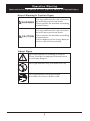
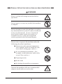
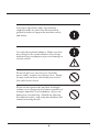
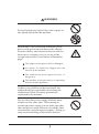
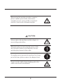
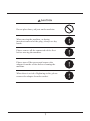
Specification:
* Natural Response Drum Head with 128 Level Force Velocities
* 11 Pre-set Drum Kit with up to 4 Variations
* Built-in Reverb Switch
* Headphone Jack
* Stereo Line-in for Portable MP3 Device
*MIDI In/Out
* Built-in Metronome
* Fully Adjustable Drum Rack
PED04 Include:
5 Drum Pads
2 Drum Sticks
1 Hi-Hat Pedal
1 Bass Pedal
1 User Manual
1 Drum Rack
1 Sound Module
1 100V~240V Auto Switch Power Adapter
7 Cables
Drum Lock
1
Operation Warning
Instruction for Prevention of Fire, Electric Shock, & Physical Injury
About Warning & Caution Signs:
WARNING
This sign indicates the risk of serious
physical injury and even death.
Please operate the machine according
to instructions.
CAUTION
This sign indicates the risk of serious
physical injury and even death.
Please operate the machine according
to instructions.
*Object damage refers to any harm or
adverse effects to household,
About Signs
This sign indicates a warning or caution.
Please read the accompanied instruction to
prevent any dangers.
This sign indicates any forbidden activity.
This sign indicates an instructional
procedure for users to follow with.
2
Always follow the instructions as described below
WARNING
Please read the following instruction before
operation.
Do not open or, in any way, modify the machine
or adapter.
Do not attempt to repair the machine, or replace
any internal parts by yourself, unless instructed
to do so by the manual. In case of technical
need, please contact with your retailer, or
customer service, or any our recognized
retailers printed on the information page.
Do not store or operate the machine under the
following described conditions:
Near areas with extreme temperature.
(For example, in the car under the sun,
near a heat venting pipe, and etc.)
In very humid environments. (For
example, in the bathroom, in the toilet,
on wet floor, and etc.)
Exposing to rain.
In the sand.
In shaking & unstable environments.
Operate the machine with ours recommended
support stands and accessories only.
3
For proper operation, make sure that the
support stands are placed on flat and stable
ground in order to support the machine safely
and stably.
Use only the included adapter. Make sure that
the voltage of the socket matches the voltage
indicated on your adapter to prevent damage or
electric shock.
Please do not over-twist or over-bend the
power cable, or place any objects on it. Doing
so may result in short-circuit that can lead to
fire and electric shock.
Please do not operate the machine with high
volume over a long period of time regardless of
using an amplifier or a headphone, to prevent
damage to your hearing. Should any hearing
discomfort results, stop using the machine and
consult a hearing doctor.
4
WARNING
Prevent letting any object like coins or pins, or
any liquid slip inside the machine.
Should any of the following situations result,
please stop operation and remove the adapter
from the socket, and consult with your retailer,
the nearest customer service, or any of the
recognized retailers listed on the information
page:
The adapter or the power cable is damaged.
An object, or liquid has slipped into the
interior of the machine.
The machine has been exposed in rain, or
has got wet.
The machine is not operating or is operating
with noticeable problems.
If there were children in the household, the
adults should be responsible of teaching the
children to follow the safety precautions
explained in the manual.
Do not share the power supply with too many
adapters at the same time. When using an
extension power supply, please make sure that
the total power usage does not exceed the limit
stated on the extension power supply. Doing so
may result in melting of the cables and fire.
5
When using the machine in other countries,
please consult your retailer, the nearest
customer service, or any of the recognized
retailers listed on the information page.
CAUTION
Always place the machine and the adapter in
areas with good airflow.
When inserting or removing the power cable
into/from the socket or the machine, always
grab the plug instead of the cable.
If you plan not to operate the machine for a long
period of time, please remove the adapter from
To prevent the cables from tangling, place the
cables out of reach of children.
6
CAUTION
Do not place heavy objects on the machine.
When moving the machine, or during
insertion/removal of the plug, always use dry
hands.
Please remove all the connected cables first
before moving the machine.
Please turn off the power and remove the
adapter from the socket before cleaning the
machine.
When there is a risk of lightning strike, please
remove the adapter from the socket.
7
Precautions
Please read the following precautions aside from the safety
instructions printed on page 1 & 2”
Power Supply
Do not share the power supply with other electronics that can
produce cable statics, for example, electric motors.
It is normal for direct current (DC) to produce heat with
extended usage, and there is no need to be worried.
Before connecting the machine to other equipments, always turn
off the power to prevent damage.
Placement/Location
Operating the machine near a post-amplifier or machines that
use high-power converters, buzzing may result. To prevent this
problem, please change the machine's facing direction, or place
the machine away from the interrupting sources.
This machine may interfere with the radios and televisions.
Please do not operate the machines near them.
Do not place the machine under sun, or near any heat source, as
high temperature may cause the machine to deform or discolor.
To prevent permanent damage, please do not expose the machine
to moist or in humid environments.
Maintenance
For normal cleaning, please use soft cloth with little or no moist
for wiping. For tougher spots, use neutral-pH and wear-free
cleaner then use dry soft cloth to wipe clean.
Never use volatile oil, diluting solutions, alcohol, or any other
kinds of solvents to prevent the machine from deforming or
discoloring.
8
Additional Precautions
During operation, please handle with care to prevent any
damage.
Do not hit or press against the display screen.
Always grab the heads of cables during insertion/removal to
prevent damage to the cables or the machine.
To prevent disturbing your neighbors, please operate the
machine at an acceptable volume, or use a headphone, especially
at nights.
Although the machine is designed to minimize unwanted noise
during operation, the percussive sound may still pass through the
floor or walls, resulting in unexpected noise. Please be careful
not to let such sound disturb your neighbors, especially at nights.
When transporting the machine, please use the original or
similar stuffing and box.
Please use our cables for connection. When using cables from
other companies, please note the following:
Some cables may consist of resistors, which may be
incompatible and result in extremely low volume. For
information about the specifications of cables, please consult
with the manufacturers.
9
Please do not hit the pads with excessive force to prevent the risk
of hurting your fingers.
10
Manual Summary
Preface
This manual includes all the operational knowledge and precautions. With
the help of this manual, users are able to understand the software and
hardware of this machine, and enjoy making use of it according to their needs.
Cha pt er Sum mar y
Hardware Introduction
This section of the manual explains the basic operation of the machine. It
introduces all the ports, power, sound output/input, MIDI, and volume
controls with clear illustrations. With the manual, users are able to assemble
the machine and start operating it with ease in no time!
Parts
This section introduces all the parts of the machine like PAD, CRASH, BASS,
and PEDAL, and illustrates the correct placement and connection of each
part.
It also explains the correct usage of CRASH and HI-HAT CLOSE, and how to
imitate actual drum set, allowing users to have a realistic playing experience.
11
Contents
2
3
8
Warning & Caution Signs
Warning
Precautions
Manual Guide
11
Hardware Introduction
11
Parts
11
Advance Learning
11
Contents
12
Introduction to Parts
14
Support stands
14
Connectors
14
Parts
Accessories
15
15
Assembly Instructions
16
16
Support Stands
Step 1
16
Step 2
17
Step 3
18
Step 4
19
Step 5
19
Step 6
20
Finished Diagram
20
21
Parts
PAD
21
CRASH
22
CONTROL BOX
23
Finished Diagram
24
12
Accessories Introduction
26
Accessories Illustration
26
Accessories Assembly Diagram & Instructions
27
Console Control
28
Console Control Illustration
28
Console Control Diagram & Instructions
29
Console Operation
30
30
Drum & Percussion Sound Patches
Style
30
Patch
31
Reverb
31
Sounds & Tones
32
33
Metronome
On/Off
33
Rhythmic Style
33
Tempo
34
13
Parts
Please make sure that you have all the necessary parts before assembly
Support Stands
A3
A1
22.5x800 (mm) main support bar x 5
12.7x400 (mm)
locking bar x 5
A2
22.5x400 (mm) floor bar with
double T-shape locks x 2
Connectors
B1
T-shape
connector x 4
B2
B3
Connector
Type A x 5
Connector
Type B x 5
NOTE
Not including the 4 T-shape
locks on the floor bars
14
Parts
Floor pad x 4
Nuts x 42
Y1
U-shape
plate x 1
Spare(2)
Spare(2)
Y2
Y4
Y3
Screws x 2
22.5mm
stopper x 2
Drivers x 2
Y6
Y5
Washer x 42
Bolts x 42
Spare(2)
Y7
Y8
Introdution
DVD x 1
Adapter x 1
Accessories
Sound module x1
Pad x 5
Pedal x 2
Z2
Z1
Drum stick x 1 set
Z3
Z5
Z4
Stereo sound
cable (1m) x 1
( BLUE )
Mono sound
cable (1m) x 6
Z7
Z8
Z6
15
Assembly Instructions
Y2
NOTE
Y3
Y4
B2
B1
Y7
Please insert the bolts and nuts to
connectors before assembly.
B3
Support Stands
Step 1
Assemble the floor pads onto either side of the two floor
bars with double T-shape locks, and place the bars parallel
to each other, with a distance equal to the length of the main
support bar. Adjust the facing direction of the T-shape locks
as according to the diagram.
Y1
A2
Y1
800mm
Y1
A2
Y1
16
B2
Step 2
B1
B2
A1
Assemble the T-shape connectors and
connector A(s) onto the main support bars.
The main support bar on the left should
have two T-shape connectors and two
connector A(s) as according to the
illustration on the left. These two
connector A(s) are for Hi-Hat and Snare.
B1
B1
The main support bar on the right
should have two T-shape connectors.
A1
B1
2~15cm
5~15cm
15~20cm
NOTE
17
Adjust the heights of all
four T-shape connectors
so that they match on
either main support bar.
Step 3
Insert the assembled
main support bars (from
Step 2) into the T-shape
locks on the assembled
floor bars (from Step 1).
Adjust as necessary to
make sure that the main
support bars are
perpendicular to the
floor bars.
NOTE
With the chair that you will be
using, you should sit on the
chair and adjust the heights of
the T-shape connectors
according to your chest and
knee heights. The lower Tshape connectors on the main
support bars should match the
height of your knees, while the
upper T-shape connectors on
the main bars should match
that of your chest.
18
B2
NOTE
BACK
Step 4
B2
B2
4CM
8CM
5CM
A1
T he remai n ing th r ee main sup p ort bars
a re for conn e ct i on bet we en the 4 Tsha p e c o nne c tors o n the m a i n s u p port
bars a nd t he 2 T-shape lo c ks o n t h e
floor bars, with the upp e r on e
a s se m b led with 3 con n ector A(s ).
These 3 c o nne c tor A(s) wi l l be u sed f or
th re e Pa ds.
Plea s e ch ec k t he d irec t ion t o w h i c h
NOTE t he 4 c on ne c t or A(s ) a r e f astcinratge. dTh. ey
sho uld f a c e t h e rea r as il lu
NOTE
FRONT
Please check the spacing of the 4
NOTE connector A(s) as illustrat e d .
St e p 5
Assemble the main support
bars as illu s trated and tight e n
th e bolts and n u ts.
A1
A1
19
Step 6
Insert the long and short locking
bars, and stoppers as illustrated to
complete the support structure.
Finished Diagram of Support Structure
22.5mm
stopper x 2
HI-HAT
A3
Y7
TOM2
TOM1
CRASH
A3
A3
A3
A3
SNARE
20
Accessories
PAD
HI-HAT
SNARE
Z1
Assemble the Pads (Hi-Hat Snare
and Tom 3) and connector B(s) as
illustrated.
B3
TOM1 Z1
TOM2
Tilt the Tom 1 and Tom 2 for
smoother playing.
B3
Z1
NOTE
When assembling the Pads and connector B(s),
match the depressed side of connector B(s) with
the protruding side of Pads.
Depression
B3
NOTE
Below are examples of wrong assembly.
21
Convex
Assemble the pads (Snare, Hi-Hat, Tom 1,& Tom 2) and
the Crash onto the support structure.
Z1 CRASH
Z1 TOM2
Z1 HI-HAT
Z1 TOM1
Z1
SNARE
22
Control Box
Z3
Y5
Following the illustration,
attach the U-shape plate onto
the back of the control box.
Position the box onto the second
main support bar (labeled as A
on the previous page), and fold
the U-shape plate upwards
around the bar.
Y6
Tighten the screws for the Ushape plate to a suitable
tightness.
23
Finished Diagram
HI-HAT
TOM1
CRASH
TOM2
Position the pedals as
illustrated to
complete the setup.
SNARE
H.H CTRL
Position the Hi-Hat
Pedal below the HiHat.
Z4
BASS
Position the
Bass/Kick Pedal in the
middle below the set.
Z4
24
Mono sound
cable
Z7
For Pad and Pedal must to use the
NOTE mono sound cable(Black).
Crash Pad
Stereo sound
cable ( BLUE )
Z6
NOTE
For Crash must to use the stereo
sound cable(Blue).
25
Accessories Introduction
H.H CTRL
HI-HAT
SNARE
CRASH
BASS
TOM1
TOM2
Using the diagram on the previous page and the
one on this page as a guide, connect the cables
to the Control Box.
For Crash, use the stereo sound cable (two
parallel black lines at the tip) for connection,
NOTE as
illustrated by
.
26
Hi-Hat
Snare
High Tom
Middle Tom
Crash Pad
Hi-Hat Pedal
Bass/Kick Pedal
Hi-Hat Pad (Labeled as ) and Hi-Hat Pedal
(Labeled as ) correspond to each other as
open and close Hi-Hat, simulating realistic
Hi-Hat playing.
27
Console Control Introduction
MIDI
About MIDI
MIDI (Musical Instrument Digital Interface) is an industry-standard
protocol that enables electronic musical instruments, computers, and
other equipment to communicate, control, and synchronize with each
other. MIDI allows computers, synthesizers, MIDI controllers,
sound cards, samplers and drum machines to control one another, and
to exchange system data.
28
DC IN
For connection of the adapter.
POWER
Switch power on/off.
NOTE
MIDI IN
To prevent damage to
speakers, always turn down
the volume before inserting
or removing sound cables.
MIDI OUT
For transmitting MIDI data.
VOLUME
For adjusting the volume.
PHONE
For connection of a headphone.
LINE OUT R
LINE OUT L
For connection of speakers or amplifiers.
LINE IN
For connection of a sound input source
like a CD player, MD player, or Mp3
player. The sound is directed to both
Phone and Line Out.
29
Console Operation
Percussion Sound Module
&Metronome
Drum Voice List
PERCUSSION SOUND MODULE
STYLE
Available Styles:
ROCK
JAZZ
METAL
BLUES
POWER
TECHO
MARCH
LATIN
TIMBALE
FUSION
30
With different style of music selected, users may select different
percussion sounds.
P. S . S o u n d s e l e c t i o n c a n b e o p e r a t e d a s i l l u s t r a t e d b e l o w.
PATCH
After choosing the style, this button
allows users to choose different sounds.
REVERB ON/OFF
This button can be used to turn reverb
on/off .
31
Styles & Sounds List
32
METRONOME
CHICK ON/OFF
This button allows users to
switch the metronome on/off.
BEAT
After turning on the metronome, these
two buttons can be used to change the
beat of the metronome.
33
TEMPO
These two buttons are be used to adjust the tempo of
the metronome. The metronome is ideal to help users
develop stable rhythm sense, and for practicing.
34