1
CRI:IF
I'ZMIIN+
MODEL NUMBER 917.258670
OWNER'S
MANUAL
"Assembly
' Operation
• Customer Responsibilities
• Service and Adjustments
° Repair Parts
CAUTION: Read and follow all safety rules and instructions before operating this equipment+
FOR CONSUMER ASSISTANCE HOT LINE, CALL THIS TOLL FREE NUMBER; 1+800+65g.59t7
I[
'r'll"l
I'.......................
i,iiilllll' "ll'll "1ii I "111'1 I i
SAFETY
Safe Operation
PracticesRULES
for Ride-On Mowers u
IMPORTANT.'
THIS CUTTING
FAILURE TO OBSERVE
THE
1°
,,
•
•
•
"
,
,,
,.
•
,
•
•
MACHINE
tS CAPABLE
OF AMPUTATING
HANDS AND FEET AND THROWING
FOLLOWING
SAFETY INSTRUCTIONS
COULD RESULT IN SERIOUS
INJURY
GENERAL OPERATION
Read, understand, end follow ell fnstruclions tn the manual
and on fhe machine before elading
Only allow responsible adults, who are famtllar wlth Ihe
instructions,Io operate the machine,
Clear the area of objecls such as recks, toys, wire etc,
whichcould be p eked up and thrownby the blade
Besure thearea tsclearof olher people before mewing Slop
machine Banyone enters the area
Never carry passengers.
Do notmow tn reverseunless absolutelynecessary Aiways
look down and behindbetore and while backing
Beaware of the mowerdischarge dlraclton enddo not point
it at anyone Do not operate the mower wghouleither the
entlre grass catcher or the guard in placeStow down before turning.
Never leave e running machine unattended. Always turnoff
blades, set parking 5rake, stop engine, and remove keys
before dismounting.
Turn off blades when not mewing
Slop engine before removing grass catcher or unclogging
chule
Mow 0nly In daylight or good artificial light
Do nol operate the machine while under the influence of
alcohoior drugs
Watch tot traffic when operating near or crossing roadways
Use extra care when loading or unloadingthe machlne into
a keller or truck.
Ill
"
DO NOT:
.
Do not lure on slopesunlessnecessary, and then, turnslowly
andgradually downhlIl,it posstble
De notmow near drep-offs dltehea, or embankments. The
mowercouldsuddenlyturn over If e wheel is over the edge
of a oligor dilch, or if an edge caves in,
Do not mow on wet grass, Reduced traction could cause
sliding
•
De not tryto stabilize the machine by pulling your foot on the
ground.
•
De not use grass catcher on sleep slopes
Never carry children They may lall oi! and be seriousy
injuredor tetedere wtlh sate machine operation
Never allow children to operale lhe machine
Usa extra care when approaching blind comers shrubs,
trees, or other objectsthat may obscure vision.
•
"
IV.
SERVICE
•
Use extra tara In handling gassltne end olher fuefs Theyere
flammable and vapors are explosive
Use only an approved container+
Never remove gas cap or add fuel with the engine
running, Allow engine to cool before refueling
Do not
smoke
•
SLOPE OPERATION
Slopes are a major factor related to loss-of-control and
ttpover accidents, whlch can result in severe Inlury or
death Al! slopes require extra caution. If you cannot back
up the slope or if you leet uneasy on It, do eel mow It.
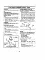
DO:
Mow up and down slopes, not across
•
Remove obstacles such as rocks, tree limbs, etc
Welch lot holes, ruts, or bumps. Uneven terrain could
ovedum Ihe machine Taft greas can hide obstscles,
"
Useslowspeed. Choosea low gaarso that you will not have
to stop or shift wh_e on the slope.
.
Follow the manulacturar's recommendations for wheel
weightsor counlerwetghlsto improve slabtllty.
,, Use extra care with grass catchers or other atlachments
These can change the stability ol the machine.
"
Keep a_ movement on the slopes slow and gradual. Do not
make sudden changes In speed or direction
•
Avoid stadtng or stoppingon e stops, If tires lose traction,
disengage the blades and proceed slowly strelghl down the
slope
CHILDREN
Tragic accidents can occur If the operator ts not alert to the
presence of children
Children are often attracted to the
machine and the mowing activity.
Never assume that
children will remain where you last saw Ihem.
Keep eh[tdran out of the mowing area and underthe watehtu
care of another responsibleadult,,
•
Be alert and lure machine oil if children enter the area
•
Borers and when backing, look behind and down for small
children
•
IL
OBJECTS
OR DEATH
•
•
•
"
•
•
•
Never refue_ the machine indoors
Never store the machine or fuel container Inside where
there is an open llama, such as a water heeler.
Never tun a machtne insidea closed area
Keep nuts and bolls, especially btade attachment bolls light
and keep equipment
n good condit on
Never tamper with safety devices
Check their proper
operalion regularly
Keep machine free ot grass tesves, or other debris build-up,
C san o or fuel spillage
Mow machine to coat before
stodng
Slop and inspect lhe equipment if you sldke an object
Repair, if necessary, before restarting.
Never make adjustmenls or repairs wilh lhe engine running.
GreessatchercomponenlearesubJectlowear
damage and
deterioration,
which could expose moving paris or allow
objects [o be thrown+ Frequenlly check components and
replace with manufaclureCs recommended parts, when necessary
Mower blades are sharp and can cut, Wrap Ihe blade(s) or
wear gloves, and use extra caution when servlclngIhem.
Check brake operalion lrequently.
Adjust and service as
,, requ_red_.........
Look for this symbol to point out important
safety
precautions,
It
means
CAUTIONIf!
BECOME ALERTIII
YOUR
SAFETY IS INVOLVED.
n.
,H
HHH,,n
=
CAUTION:
Always disconnect
spark plug
wire and place wire where It cannot contact
spark plug In order to prevent acctdenlal
starting
when setting
up, transporting,
adjusting or making repairs.
WARNING
A
The engine exhaust from this product contains
chemicals known to the State of California to
cause cancer, birth defects, or other reproductive harm,
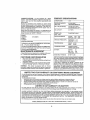
CONGRATULATIONS
on your purchase of a Sears
Tractor. It has been designed, engineered and manufactured to glve you the best posslbIe dependability
and
performance.
Should you experience any problem you cannot easily
remedy, please contact your nearest Sears Authorized
Service CentedDepartment
Department
We have competent, well-trained technicians and the proper tools to
service or repair this tractor_
Please read and retain this manual
The Instructions will
enable you to assemble and maintain your tractor properly.
Always observe the "SAFETY RULES".
MODEL
NUMBER
SERIAL
NUMBER
917 258670
PRODUCT
SPECIFICATIONS
HORSEPOWER:
19.5
GASOLINE CAPAC!TY
AND TYPE:
3.5 GALLONS
UNLEADED REGULAR
OIL TYPE (APfoSFtSG}:
SAE 30 (above 32'_F)
SAE 5W-30 (be!ow 32°F}
OIL CAPACITY:
3 0 PINTS
SPARK PLUG:
{GAP: O3O3
CHAMPION RJ19LM
VALVE CLEARANCE:
INTAKE:
004" - 006"
EXHAUST: 007"-.009"
GROUND SPEED (MPH);
FORWARD: 0 - 5.5
REVERSE: 0-2 4
TiRE PRESSURE:
FRONT: 14 PSI
REAR:
10 PSI
CHARGING SYSTEM:
3 AMPS BATTERY
5 AMPS HEADLIGHTS
BATTERY:
AMP/HR:
MIN COA:
CASE SIZE:
BLADE BOLT TORQUE:
30-35 FT. LB&
DATEOF PURCHASE
THE MODEL AND SERtAL NUMBERSWIL L BE FOUND
ON A PLATE UNDER THE SEAT
YOU SHOULD RECORD BOTH SERIAL NUMBER AND
DATE OF PURCHASE AND KEEP IN A SAFE PLACE
FOR FUTURE REFERENCE.
MAINTENANCE
AGREEMENT
A Seat's Maintenance Agreement is avaifab_e on this product Contact your nearest Sears store for details:
CUSTOMER
•
•
•
RESPONSIBILITIES
Read and observe the safety rules..
Follow a regularschedule In maintaining, ca#ng for and
using your tractor,
Follow the instructions under "Customer ResponsibItt*
ties" and "Storage" sections of this owner's manual.
WARNING:
This tractor is equipped with an internal
combustion engine and should not be used on or near any
unimproved forest-covered, brush-covered or grass-coy-
LIMITED
TWO YEAR
WARRANTY
30
240
U1R
ered land unless the engine's exhaust system is equipped
with a spark arrester meeting applicable local or state laws
(if any) If a spark arrestor is used, it should be maintained
in elfective working order by the operator,
In the state of Caitlornia the above is required by law
(Section 4442 of the CaIiIornta Pubtic Resources Code).
Other states may have simitar laws.. Federal taws apply on
federal lands° A spark arrester for the muffler is available
through your nearest Sears Authorized Service Center/
Department (See REPAIR PARTS section of this manual).
ON CRAFTSMAN
RIDING
EQUIPMENT
For two (2) years from the dale o! purshase, {(this Craftsman Riding Equipment Is maintained, lubricated and tuned up according
to the {nstrucltonstn the owner's manual, Sears will repair or replace,free of charge, any pads found to be defective tn material or
workmanship,
This Warranty does not cover:.
•
Expendable items which become worn during normal use, suchas blades, spark plugs, air cleaners, belts, etc.
•
Tire repJacementor repaircaused by punctures from outsideobjecfe, such _s nails, thorns,stumps, or glass.
•
Repairs necessary because of opereler abuse, negligence, improperstorageor accident or the failure to maintain _he
equipment accordingto the Insiructiona containedtn the owner's manual
,
Riding equipment used forcommercialor rental purposes
LIMITED
90 DAY WARRANTY
ON BATTERY
For ninety (90) days from date of purchase, tl any battery incJudedwilh th}s tiding equipment proves defective in material or
workmanship and our testingdetermines _hebattery wttlnot hold a charge,Sears will replace the battery at no charge
IN-HOME WARRANTY
SERVICE ON YOUR CRAFTSMAN
RIDING EQUIPMENT
IS AVAILABLE
AT NO-CHARGE
FOR 80
DAYS FROM THE DATE OF PURCHASE.
PLEASE CONTACT YOUR NEAREST SERVICE CENTER.
AFTER 80 DAYS FROM
THE DATE OF PURCHASE, WARRANTY SERVICE IS AVAILABLE BY TAKING YOUR CRAFTSMAN
RIDING EQU|PMENT TO
YOU R NEAREST SEARS SERVICE CENTER.
(IN-HOME WARRANTY SERVICE WILL STILL BE AVAILABLE
AFTER 30 DAYS
FROM THE DATE OF PURCHASE
BUT A STANDARD
TRIP CHARGE WILL APPLY)
THIS WARRANTY
APPLIES ONLY
WHILE THIS PRODUCT
iS tN THE UNITED STATES
This Warrenty
gives you specific ]egel rights, end you may also have other rights which may vary Item state to state.,
SEARS, ROEBUCK
AND CO,, D/817 WA, HOFFMAN ESTATES,
IL 60179
TABLE OF CONTENTS
SAFETY RULES ......................................
...................... 2
PRODUCT SPECIFICATIONS
.......................................
3
CUSTOMER RESPONSIBILITIES
..................... 3j 17-20
WARRANTY .............................................................
L,.. 3
TABLE OF CONTENTS ................................................
4
INDEX ............................................................................
4
TRACTOR ACCESSORIES
..........................................
5
ASSEMBLY ................................................................
7-10
OPERATION ............................................................
11-16
MAINTENANCE SCHEDULE ......................................... ! 7
SERVICE AND ADJUSTMENTS ............................
21-27
STORAGE .....................................................................
28
TROUBLESHOOTING
............................................
29-30
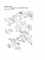
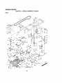
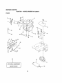
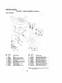
REPAIR PARTS o TRACTOR .................................
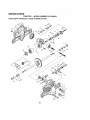
32-47
REPAIR PARTS - ENGINE ...................................... 4B-53
PARTS ORDERING!SERVICE
................... BACK PAGE
INDEX
A
Accessories ................................ ;......... 5
Adjuslmenls:
Brake ................................................
24
Carburetor .....................................27
Mower'..
Front*To-Back., ,.........................
22
Side-To-Side ......................
22
Throttle Control Cable ........... 26-27
Air Filler, Engine..................................19
Atr Screen, Engine
19
Aesembty ......................................... 7-10
B
Baltery:
Charging .........................................18
CIeaning ..................................
fB
Starting w]th Weak Battery .............
26
Slorage ..........................................28
Terminals ................................. 18
Belts:
Mo!ton Drive
RemovaVRep{asemenl
24
Mower Drive
RemovaVReplasement ........... 23
Mower Blade Drive
Removaf/Rep_asement .............23
Blade:
Sharpening ......................................18
Replacement.....................................
18
Brake Adjustment ............................ 24
C
..................................
E
Electr;cal:
Interlocks end Relays.................. 26
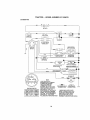
Schematic ................................... 31
Wfdng Diagram ............................ 32
Engine:
Air Rilor ................................
t9
Air Screen ................................ 19
Ooot}ng Fins,Engine .................. 20
011Change
Oil Levef
14,19
Oil Type ...................................... 19
Preparation .................................. 14
Repatr Pads ............................46,53
Sladtng ._............................... _....14
Storage ... ................................ 28
.........................
.................
1
,
..........
9
O
Oil:
Cold Weather Conditions ...... t4,19
Engine .................................
19
Storage ....................................... 28
Operallon .................................
11-t 8
Operaling Mower ................................
14
OplJons:
Accessories .....................................
5
Spark An'ester ..........................
3.40
P
Parking Brake ................................ t2-13
Porte Bag ..........................................................
8
Pads, Replacamen_Repetr ........ 32-47
Product Bpeclftcatlons ......................... 3
R
Repair Pads ...................................
32-47
F
Filters:
S
Air ..........................................
19
Fuel .....................................
20
Safety Rules ......................................... 2
Seat .......................................................
8
Fuel:
Service and Adjuslmeols ...............
21-27
Type ................................
14
Brake .......................................... 24
Storage
Carburetor .......................................27
Fuse ................................................... 28
Fuse ............................................ 28
G
Hood Removal/Installation....... 28
Gauge WheeFs
g,14
Motion Odve Belt
H
Removal/Replacemenf
24
Hoed Removat/Instalfetton ..............
26
Mower Drive
RemovaIlRep_acement .......... 23
L
Mower Btade Drive Belt
Leveling Mower Deck ................... 21-22
ReraovaL"Replacement .........
23
Lubdcalion Chart ...............................
17
CarburetorAdjustment ..................... 27
Mower Adjustment:
Controls, Traclor ............................
13
M
FronMo-Back
22
CustomerResponsibilities .............
3,17-20
Maintenance Schedule
;................ 17
Side4o-Side........................... 22
Engine:
Mower,
Mower Installation ............................
21
Air Ftlter ........................................
19
Adjustment, Front4o-Beck
22
Mower Removal ............................
L 21
Atr Screen, Engine ...............
19
Adjustment, Side-to-Side .............22
Tire Care .................................8,18,25
Battery .................................... 18
Blade Sharpening..........................
18
S!ope Guide Sheet ............................. 55
Cooling F_ns,Engine............. lg
Blade Replacement ................. 18
Spark Pluga ......................................... 20
Engine Oil ............................... 20
Cutting Height .................................13
Specifications ............................................
3
Fuel Filter ................................ 20
InaIaIlation ................................ g,21
Starting the Engine ....................... I4.-15
Spark Plugs ..................
18
Operation .............................. 11-18
Steering Wheel .............................. 7,25
Tractor.
RemovaJ...................................... 21
Stopping the Tractor ...........................
13
Blades ..................................... 1B
Mowing Tipe ..................................... 18
Slorage ................
,..................
28
LubricationChad .........................
17
Muffler
20
T
Maintenance Schedule .........:., 17
Spark Arrasler ......................... 3,40
Ttre Care ...... .................. 8,18,25
Thraltle Oontro_ Cable Adjustment ... 28
Muteher Plate ...................................... 10
Tires
B,I8,25
Cutting Helght, Mower ............................
13
Trouble ShootingChad .................. 29-30
Transexle Repair Patte ............... 46-47
W
Warranty ................................................
3
Wiring Diagram ...................................
32
Wldng Schematic ................................
31
...............
...............................
28
.....................................
...........
............................
.................................................
...........
.....................................................
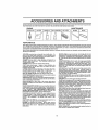
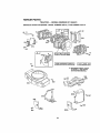
ACCESSORIES AND ATTACHMENTS
These accessoriesendattachments were available throughmost Sears retail outlets and service centers when thetractorwas purchased.
Most Sears stores can order these items tar you when you provide the modal number of your Iractor,
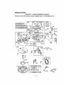
MAINTENANCE
ENGINE
SPARK
PLUQ
GAS
CAN
ENGINEOIL
FUEL STABILIZER
AIR FILTER
BLADES
BELTS
PERFORMANCE
Sears offersa wide varietyof attachmentsthat f_tyourtractor Many of these are listed belowwithbdel explanationsofhow they can help
you, Thtsftetwas current at the time el publication;however, it may changetn future years - more altaehmenls may be added, changes
may be made tn theee altachments, or some may nolongerbe evailable or fit your medel Contsct your nearest Seare store for the
accessories and attachments that ere available for your tractor,
Most of these eItechments do not require additional hitches or conversionkite (those thai do are Indicated) and are designed for easy
attaching and detaching
AERATOR promotes deep root growthfor a healthy lawn Ta.
pered 2.5-Inch steel spikes mounted on 10-inch d_ameler discs
puncture holes in soil at ctose Intercals to let moisture soak In
Steel weight tray for Increasedpenetration
BAGGER lets you collect grass sIIppthgs and ]eaVes for a
healthier, nearer looking lawn Two Permanex containershem
3e-gallon plastic bags
BUMPER protects front end of Iractarfrom damage,
CARTS make hauling easy Variety of sizes ava_fable, plus
accessories such as aide panel kIls, tool caddy, cart cover,
protective mat and doily
CORING AERATOR takes smelt plugs out of soil to allowmois*
lure and nutrients to reach grass mo!s 36-thch swath 24
hardenedsteel coringtips. 150 _b.capacity weight tray
EASY OIL DRAIN VALVE makes at| changeseas_er,fasler
FRONT NOSE ROLLER canters In front ofmowerdeck 1oreduce
chances of =scalping" on uneven terrain.
GANG HITCH letsyou tow2 or3 pull-behthdattachments atonce,
such as sweepers, dethetshers,aeralors (net foruse with reltere,
cads or other heavy attachmenle)
GAUGE WHEELS on both sides of the mower deck reduce
chances of"scalpthg" on uneven terrain. Formower decks not so
equipped
MULCH RAKE/DETHATCHER loosens soil end flipsthatch and
mattedteaves to lawn sudace for easypickup. Twenty apdeg time
teeth Usefuttopreparebareareae!orseedthg. Avatlablelorfront
or rear mounting. HIGH PERFORMANCE REEL-ACTION
SPRING 'I"INE DETHATCHER covers 86_]nch wide path and
tosses thatch tnte large hopper Mounts behind tractor
MULCHING CLOSEJOUT PLATE KIT, onceInstalled, lets you
mulch, discharge or bag ct_ppinge (bagger optional) without
changing blades. For modefs not equipped as 3.Ira1 Convertible
mowers
See "MOWER" in the Repair Pads section of this
manual
RAMP TOPS AND FEET let you Ioad and unload tractor from a
pickuptnJck. Use with 2 x 8 or 2 x 10 lumber
ROLLER tar smoother lawn surface° 38.,inch wide, 18-thch
dlametarwater-tightdrumholds up to3gOlbs. of wetghL Rounded
edges prevent harm to tuff Adjustable scraper automatically
otaana drum,
SNOW BLADE for snow removal oniy. '14-1nchhlgh, 48-Inch wide
bladaclears42qnchpathwhenangledleltordght.
Raises, fcwere
withside lever. Adjustable skids; replaceable, reversible scraper
bar. (Use wl!h tire chainsand wheelweightsand/or rear draw_ar
weight ,)
SNOWTHR OWER has 40-thch swath. Drum*type auger handIes
powdery and wet/heavy snow Mounts easily with stmp_e pin
arrangement D_schargechuteadjusts from tractorseat. 6-Inch
diameter spoutdischarges snow 10 to 50 feet. Lift controlledat
tractor seat. (Use Withchains and wheel weights end/or rear
drawbar welght )
SPRAYERS use 12-volt DC etectdc motor that connects to the
tractor battery or ether 12-vott source. Includes booms tar
automaticspraying end hand held wand for spot spraying, Wand
has adjustable spray I_attern, For applytng herbicides, Insecticides, fungicides and liquid lediltzers.
SPREADERISEEDERS make seeding, fartitlztng,and weed killtng easy. Broadcast spreaders are a{so useful forgranular deIcers and sand.
SWEEPERS let you collect grass clippingsand leaves
TILLER has 5 hpengine and36-Inchswath toprepare seed beds,
cultivate and compost garden residue Ttl]er has its own bulll..In
lift and depthcontrolsystem and does NOT requirea sleeve hitch.
Fits any lawn yard or garden tractor. Simply hookup tothe tractor
drawbar and gel Optional accessories convert unit for
dathatchtng, aerating, hitting, without toots
TIRE CHAINS ere heavy duty; ctosely spaced extraqarge cross
links give smooth dde, outstandingtraction.
TRACTOR CAB has heavy du|y vinyl' fabdc over tubular steel
frame, ASS plastictop; _learptast|c windshield offers 360 degree
v[slblllty.Hinged metal doorswith catch. Keeps operator warm
and dry. Remove vthyl sides and wthdshiefdsfor use as sun
protector tn summer. Optional accessories Include: tinted!
tempered solid safety glass wtedshie_dwithhandoperatedwtper,
12-voltamber caution light for mounting on cab top
VACS for powerful coltecllon of heavy grass clippingsand leaves.
Optional wand attachment to pick up debds In herd-to-reach
places. VAC/CHIPPER Includes a chipper-shredder.
WEIGHT BRACKET tar drawbar for snow removal appllcallenso
Uses (!) 55 lb weight
WHEEL WEIGHTS lor rear wheels provide needed traction for
snow removal or dozing heavy matedats i
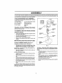
CONTENTS
OF HARDWARE
Parts Bag contents shown full size
(1) Large Flat Washer
PACK
Parts packed separately in carton
1) Hex Bolt
3t8-16 x 1
Seat
Video
Cassette
Loekwasher 3/8
(1) Locknut
(1) Hex Bolt
Steering
Wheel
_ \._) y
Mulcher
Plate
511648 X Iq14
i
,i
(1) Shoulder
Bolt 5/16-18
i
i
(1) Hex Beat 112-13 x 1
Steering
Boot
Manual
(1) Washer
17t32 x
1-3116,x 12
Gauge
Paris Bag
Parts bag contents not shown full size
, Lock
1/2
(_(2)
(2)Le k{:
Washers #10
[
_
(2) Weld
,..,
t(_
I
(2) Washers _,
I 3116 x 3t4
_
] I x16Gauge
x 7t8
Washers
x 14 Gauge
318
(2) Shoulder
Bolts
_
)
(2) Gauge
(2) Center-
Wheels
/
Iock Nuts
Steering Wheel
Adapter
Nuts #10
(4) Retainer Spdn
[single loop)
(3) Retainer
Springs
(double loop)
_(2)
Front Link Assemblies
Assemblys
(2) Hex Bolts
1/4-20 x 3t_, _k_(2)
_L'_j_
Hex Nuts
1/4-20
Steering
Wheel
_-_
(2) Keys
(2) Lock
9/32
i
Washer,,
Washers
i
in
_
114 _w,/
Slope Sheet
i
i
Steering
Extension
Shaft
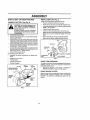
ASSEMBLY
i
u n
ii
i
i
u
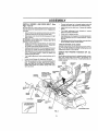
Your new tractor has been assembled at the factory wtth exception of Ihose parts left unassembted for shipping pu_'poses_
T_ ensure sa_e and pro_er o_erati_n _f y_urtrac_or aI_part_ and hardware yod assembIe mus_ be _igh_ned secure_y_ Use
the correct tools as necessary to insure proper tightness,
TOOLS
REQUIRED
FOR ASSEMBLY
A socket wrench set will make assembly easier. Standard
wrench sizes are Hsted
(1) 9t16" wrench
(2) 7t16" wrenches
(2) I/2" wrench
(1) 3/4" Socket w/drive rachet
Phillips Screwdriver
Tire pressure gauge
(!)
Utility knife
Pliers
3/4" wrench
When right or felt hand is mentioned tn this manual, It
means when you are in Ihe operating posilion (seated
behind the steering wheel).
TO REMOVE TRACTOR
UNPACK CARTON
•
•
•
.
FROM CARTON
Remove all accessible loose parts and parts cartons
from carton (See page 6)_
Cut, from top to bottom, along lines on all four come.re
of carton, and ray panels flat
Remove mower end package materials
Check far any additional loose parts or cartons and
remove,
BEFORE
ROLLINGTRACTOR
5t16 HEX
BOLT
5/16 LOCKNU_
OFF SKID
ATTACH STEERING WHEEL (See Fig. 1)
ASSEMBLE
EXTENSION
SHAFT AND BOOT
•
Slide extension shaft onto lower steering shaft. Align
mounting holes In extension end lower shafts and
install 5/t6 hex bolt and Iocknut. Tighten securely
IMPORTANT: TIGHTEN BOLT AND NUT SECURELY TO
t8-22FT
LBSTORQUE
•
Place labs of steering boot over tab slots tn dash and
push down to secure
INSTALL STEERING
FIG. 1
TO ROLL TRACTOR OFF SKID (See Operation section for location and function of controis)
•
Press !ift fever plunger and ratse attachment lifHever to
its highest position
WHEEL
•
Position front wheels of the tractor so they are polnttng
straight forward.
•
Release
pedal
•
S!Ide steedng wheel adapter onto steering shaft extension.
•
•
Position steering wheel and sleeve assembly so cross
bars are horizontal (lett to right) and slide onto adaple r.
PIace freewheel control in freewheeling position
disengage transmission (See "TO TRANSPORT"
the Operation section of this manual)
Rotl tractor backwards off skid.
•
Assemble targe fiat washer, 318 lock washer, 3/8 hex
belt end tighten securely.
•
Snap steering
wheel,
wheel Insert into center
of stee_ing
•
Remove protective plastic from tractor hood and grill.
IMPORTANT: CHECK FOR AND REMOVE ANY STAPLES
{N SKID THAT MAY PUNCTURETIRES WHERE TRACTOR
tS TO ROLL OFF SKID
,'
"
parking
brake
by depressing
Remove banding holding dlscharge
tractor,
clutch/brake
to
tn
guard up against
ASSEMBLY
HOW TO SET UP YOUR TRACTOR
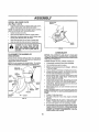
INSTALL SEAT (See Fig. 3)
Adjust seat before tightening adjustment
CONNECT BATTERY (See Fig. 2)
boll
•
Removecardboardpackingon seatpan
•
Place seat on seat pan and assemble
•
Assembte adjustment bolt, lock washer and flat washer
loosely Do not tighten..
•
Tighten shoulder boit securely
i
nals, Before connecting battery, re,.
CAUTION:
not short battery
termimove
meta!Do bracelets,
wristwatch
bands, rings, etc.
Positive terminal must be connected
first to prevent sparking from accidental groundi_qg.
•
Lower seat into operating position and sit on seat.
•
Slide seat until a comfortable position is reached which
allows you to press clutcl',/'orake pedal all the way
down,
-
Get oft seat without moving its adjusted posltlon.
•
Raise seat and tighten adjustment
Lilt hood to raised position,
•
Open terminat access doors, remove terminal protec v
tire caps and discar&
•
If thts battery is put Into service after month and year
indicated on label (label located belween terminals)
charge battery for minimum of one hour at 6-t o amp&
•
First connect RED battery cable lo positive (+) battery
terminalwith hex bolt, fiat washer, lock washer and hex
nut as shown_ Tighten securely..
•
Connect BLACK grounding cable to negative (-) battory teh'n!nal with remaining hex bolt, liar washer, lock
washer and hex nut. Tighten securely.
Close terminal access doors
,
Inspection
ware).
bolt securely
SEAT
SEAT PAN
Use terminal access doors for:
•
shoulder bolt.
=LATWASHER
tot secure connections
(to tighten hardBOLT
.
•
inspection for corrosion
Testing battery.
FIG, 3
•
Jumping (if required)
CHECK
.
Pedodic charging.
The tires on your tractor were ovednflated at the factory for
shipping purposes. Correct tire pressure Is tmpodant tor
best cutting performance.
LOCK
HEX NUT
FLAT
WASHER
O1SCARD TERMINAL
PROTECTIVE CAPS
HEX
BOLT
•
TIRE
PRESSURE
Reduce tire pressure to PSi shown in "PRODUCT
SPECIFICATIONS'
on page 3 of !his manual.
CHECK
BRAKE SYSTEM
After you learn howto operale yourtractor,check to see
that the brake Is properly adjusted. Bee "TO ADJUST
BRAKE" in the Service and Adjustments section of this
manual,
TERMINAL
ACCESS
DOOR
CABLE
NEGATIVE
(aLACK)
CABLE
FIG. 2
ASSEMBLY
i,ll
INSTALL
MOWER
AND
DRIVE
BELT
(See
•
Figs° 4 and 7)
•
Be sure tractor is on leve_ surface and mower suspension
arms are raised with attachment lift control Engage parktng brake
•
Cut and remove Iias securing anti-sway bar and belts.
Swing anti-sway bar to left side of mower deck
•
Slide mower under tractor with discharge guard to right
side of tractor.
IMPORTANT,' CHECK BELT FOR PROPER ROUTING IN
ALL MOWER PULLEY GROOVES
INSTALL BELT INTO
ENGINE PULLEY GROOVE.
•
•
Instal! one front link in top hole of the L.H, front mower
bracket and L H. front suspension bracket Retain with
two singre loop relatner springs as shown
i
lliNi
Conneot anli-sway bar to chassis bracket under left
footrest and retain with double loop retainer spflng.
Install clutch rod in ciutch lever. Secure with relainer
sprtng_
,,
Turn height adjustment knob clockwise to remove
slack from mower suspension.
,'
Raise deck to highest position.
•
Assemble gauge whee}s as shown using !ong sh0ulder
bolts, 3/8 washers, and3tS-16 centerlocknuts
Tighten
securely.
•
Adjustgauge wheefs before operating mower as shown
tn the Operation section of this manual.
CHECK
MOWER
LEVELNESS
instaiI second fronl tink in R H. front suspension bracket
and retain with single loop retainer spring as shown.
For best cutting results, mower should be properlyleveled,
See "TO LEVEL MOWER HOUSING" In the Service and
Adjustments section of this manual.
SJide right side of mower back and install link in top hole
of R,H front mower bracket. Retain wfth single loop
retainer spring as shown.
CHECK
BELTS
•
Turn height adjustment knob counterclockwise
stops.
•
Lower mower linkage with attachment
,,
Place the suspension arms on outward potnting deck
pins. If necessary, rock and raise front of mower to
align deck pins with the holes in suspension arms.
Retain with double loop retainer springs with loops
down as shown
CHASSIS
BRACKET
until it
FOR PROPER POSITION OF ALL
See the figures that are shown for replacing motion, mower
drive, and mower blade drive belts In the Service and
Adiuslmentssec_ionofthismanua_.
Verify thai the belts are
routed correctly
lift control
CLUTCH
LEVER
RETAINER
SPRING
FRONT
SUSPENSION
CLUTCH
ROD
SUSPENSION
ARMS
DOUBLE LOOP
RETAINER SPRING
(outward po{nting
deck pins)
iNGLE
LOOP
RETAINER
SPRINGS
FRONT
MOWER
BRACKET
SHOULDER
BOLT
318-16
CENTER
LOCtGNUT
3_ WASHER
DOUBLE LOOP
RETAINER
ANTI,,SWAY
SPRING
BAR
USE PLIERS FOR
RETAINER SPRINGS
iDLER
/
PULLEY
DtSCHARGE
FIG. 4
GUARD
=
,,,,,, =,
ASSEMBLY
'
'
= i_=
=
v
=
==
= =
i=
INSTALL MULCHER PLATE
(See Figs, 5 and 6)
•
DEFLECTOR
SHIELD
Install two fetch hooks to mulcher plate us{rig screw,
washer, lock washer, and weld nut as shown,
NOTE: Pro*assemble weld nut to latch hook by fnseding
weld nut from the top with hook pointing down
•
T_ghten hardware securely,
•
Raise and hold deflector shield in upright position,
•
Place front Of mulch er plale over front of mower deck
Opening and sTida into place, as shown°
,,
Hook front latch into hole on front of mower deck
•
Hook rear talch into hole on back of mower deck.
_LATCH
HOOK_
guard from mower_ Raise and hold
CAUTION: Do r_0t r_move discharge
guard when attaching muloher plate
and allow it to rest on plate while in
operation.
FIG. 6
,/CHECKLIST
TO CONVERT
DISCHARGING
TO BAGGING
OR
BEFORE YOU OPERATE AND ENJOY YOUR NEW
TRACTOR, WE WISH TO ASSURE THAT YOU RECEIVE
THE BEST PERFORMANCE AND SA TISFA C TION FROM
THIS QUAt.tTY PRODUCT_
S_mp_yremove mulcher plate and store tn a safe place.
Your mower is now ready for discharging or installationof
optional grass catcher accessory,
NOTE: It is not necassary to changeblades. The muicher
blades are designed for discharging and bagging also.
PLEASE REVIEW
HOOK POINTS
DOWN
WELD NUT
FROM THE TOP
LOCK
WASHER
WELD_
NUT
_
LOCK
WASHER
WELD
NUT
CHECKLIST:
Alt assembly instructions have been completed.
v"
No remaining
,/"
Battery is properfy prepared and charged,
1 hour at 6 stops),
loose parts in cation.
(Minimum
/
Seat ls adjusted comfortably
."
All tires are properly inflaled, (For shipping purposes,
the tires were overinflated at the factory)°
/
Be sure mower deck is properly leveled side.to-side/
front-to-rear for best cutting results, (Tires must be
properly inflated for leveling).
,z
Check mower and drive bells, Be sure they are rouled
properly around pulleys and inside all bait keepers,
/
Check widng, See that all connections
and wires are properly clamped.
/
Before driving &actor, be sure freewheel control is in
drive position,
SCREW
HOOK
THE FOLLOWING
,/
and tightened securely,
are still secure
WASHER
WHILE L EARNING HOW TO USE YOUR TRACTOR, PAY
EXTRA ATTENTtON TO THE FOLLOWING IMPORTANT
ITEMS;
MULCHER
PLATE
•,/
Engine olt ls at proper level,
,/
Fuel tank ts _fed with fresh, clean, regular unleaded
gasoline,
,,z
Become familiar with all controls - their Tocation and
funcltan. Operate them before you start the engine,
,/
Be sure brake system is in safe operating condition,
/
it ts important to purge the transmissfon before operetIng your traclor for the first time. Follow proper starting
andlransmission purging instructions (See "TO START
ENGINE" and "PURGE TRANSMISSION"
in the Operation section of this manual).
FIG. 5
10
,Lu! ,,,H H i= = =
==
i=ll= ii
OPERATION
These symbols may appear on your tractor or in literature supplied with the product,
Learn and understand their meaning
BATTERY
CAUTION OR
WARNING
REVERSE
FORWARD
FAST
SLOW
ENGINE ON
ENGINE OFF
OIL PRESSURE
CLUTCH
L1GHTS ON
UGHTS OFF
FUEL
CHOKE
MOWER HEIGHT
PARKING BRAKE
LOCKED
UNLOCKED
DIFFERENTtAL
LOCK
L
REVERSE
NEUTRAL
HIGH
LOW
m
MOWER
LIFT
DANGER,
ATTACHMENT
CLUTCH ENGAGED
ATTACHMENT
CLUTCH DISENGAGED
IGNITION
HYDROSTATIC
FREE WHEEL
(Hydro Models only)
KEEP HANDS AND FEET AWAY
11
KNOW YOUR TRACTOR
READ THIS OWNER'S MANUAL AND SAFETY RULES BEFORE OPERATING YOUR TRACTOR
Compare the iltustrations with your tractor to familiarize yourseff with the locations of various controls and adjustments,
this manual for future reference.
CHOKE
CONTROL
LIGHT
SWITCH
POSITION
ATTACHMENT
CLUTCHLEVER
AMMETER
Save
LIFTLEVER
PLUNGER
THROTTLE
CONTROL
ATTACHMENT
LIFT LEVER
©
CLUTCW
BRAKE
PEDAL
IGNITION
SW_CH
HEIGHT
ADJUSTMENT
KNOB
FREEWHEEL
CONTROL
PARKING
BRAKE
MOTION
CONTROL
LEVER
APPROX,
SPEED
3 MPH
2MPH
1MPH
FIG. 7
OUr tractors conform to the safety standards
ATTACHMENT
mower blades,
tractor.
LIGHT SWITCH;
THROTTLE
of the Amedcan Nattonat Slandards
CLUTCH LEVER: Used to engage the
or other attachments mmmted to your
Turns the headlights
CONTROL;
MOTION cOWrROL
tion of the tractor,
LIFT LEVER PLUNGER: Used to re_ease attachment Hit
lever when changing its position,
Used to control engine speed,
Locks c_utch/brake pedal
IGNITION
engine,
into the
SWITCH:
Used for staffing
HEIGHT ADJUSTMENT
cutting height,
FREEWHEEL CONTROL:
Disengages transmission for
pushing or slowly towing the tractor with the engine off.,
CHOKE CONTROL;
LEVER: SeIects the speed and direc-
ATTACHMENT LIFT LEVER: Used to raise and lower the
mower deck or ether attachments mounted to your traclor,
on and of L
CLUTCHIBRAKE PEDAL: Used fordec_utchtng and braking the tractor and starting the engine,,
PARKING BRAKE:
brake posit}on.,
Instltule,
AMMETER:
(-),
Used when starting a cold engine,
12
and stopping
the
KNOB_ Used toadjust the mower
Indicates battery charging (+) or dlssharglng
i
OPERATION
,,,,,,,,,,,,,,,,,,,,,i,,,,,,,,
i,,
, ,,,
i,
i
,1
ii ii
i
In severe eye damage,, Always wear safety glasses or eye shields while operating your tractor
or performing any adjustments or repairs° We recommend a wide vision safety mask over the
spectacles
or standard
safety glasses.
,.......
HOW TO USE YOUR TRACTOR
TO SET PARKING BRAKE (See Fig, 8)
Your tractor Is equipped with an operator presence sensing
switch.
When engine is running, any atlempt by the
operator to leave the seat without first setting lhe parking
brake Wlil shut off the engine.
•
Depress c_utch/brake pedal into full "BRAKE" position
and hold.,
•
,,,,i J, LI
CAUTION;
,
Place parking brake lever in "ENGAGED" position and
release pressure from clutch!brake pedal, Pedalshould
remain {n "BRAKE' position. Make sure parking brake
wilI hold tractor secure.
THROTTLE
CONTROL
,
Always
stop tractor com-
!
ptetely,
described position;
above, before
leavIng
the as
operator's
to empty
II
grass catcher, etc,
I
TO USE THROTTLE CONTROL (See Fig° 8)
Always operate engine at fu_l throttle,
•
Operating an_Ina at less than full throttle reduces the
battery charging rate.
•
Full throttle offers the best bagging and mower perfor_
mance.
:'
ATTACHMENT CLUTCH
LEVER"ENGAGe'
POSfffON
"DISENGAGE"
CHOKE
CONTROL
,
NOTE: Under certain conditions when tractor is standing
tdtewlth the engine running, hot engine exhausl gases may
cause "browning" of grass, To eliminate this possibtlffy,
always stop engine when stopping tractor on grass areas.
TO USE CHOKE CONTROL (See Fig. 8)
Use choke control whenever you are staritng a cold engine
De not use to start a warm engine.
•
To engage choke control, pull knob duL Slowly push
knob in to disengage.
TO MOVE
FORWARD
AND
BACKWARD
The direction and speed of movement
motion control lever.,
•
PARKSNG BRAKE
"ENGAGED"
POSITION
CLUTCHfBRAKE
PEDAL"DRWE"
POSITION
,,
•
HEIGHT
Turn knob clockwise (('_)
to ra{ss cutting height.
Turn knob counterclockwise
(l#-'_)to
tower cutting
height.,
The cutting height range Is approximatefy 1-1/2" to 4"., The
hetghls are measured from the ground to the blade tip wlth
the engIRe not running, "These heights are approximate
and may vary depending upon soil conditions, height of
grass and types of grass being mowed.
•
The average lawn should be cut to approximately 2-1/2
inches during the cool season and to over 3 inches
during hot months. For healthier and belier looking
lawns, mow often and attar moderate growth.
.
For best cutting performance, grass over 6 inches in
height should be mowed twice
Make the first cut
relalively high; Ihe second to desired hetghL
Lever to "DISENGAGED"
P0sit{0n,
GROUND DRIVE •
Dope"ass clutch/brake pedal into full "BRAKE" position
•
Move motton control lover to neutral (N) position.
IMPORTANT,'
THE MOTION CONTROL LEVER DOES
NOT RETURN TO NEUTRAL (hi) POSITION WHEN THE
CLUTCHIBRAKE PEDAL tS DEPRESSED
ENGINE •
Move throltle centre! to stow (,,_h.) position.
NOTE:
Failure to move throttle control to slow (*_!.)
posttton and allowing engine to {die before stopplng may
cause engine to "backfire".
"
Turn ignition key to "OFF" posit_on and remove key.
Always remove key when leaving tractor to prevent
unauthorfzed use.
,
CUTTING
•
•
STOPPING (See Fig, 8)
clutch
by the
The cutting height is conlrofled by tuming the height adjustment knob in desired direction.
FIG. 8
MOWER BLADES •
Move attachment
Is controlled
Start tractor with motion control lever In neutral (N)
position,.
Release parking brake and clutch/brake pedal,
Slowly move motion control lever to desired position..
TO ADJUST MOWER
(See Fig. 8)
"DISENGAGED"
POSITION
HEIGHT
ADJUSTMENT
KNOB
(See
Fig. 8)
MOTION CONTROL
TO ADJUST
GAUGE
WHEELS
(See Fig. 9)
Adjust gauge wheels with tractor on a fiat levst surface.
•
Never use choke to stop engine
13
Adjust mower to desired cutting height (See "TO ADJUST MOWER CUTTING HEIGHT' _nthe Operation
section of this manual),
OPERATION
•
•
If stopping is absolutely necessary push clutch/brake
pedalqu_ckly to brake pesilton and engage parking
brake,
•
Move motion control lever to neutral (N)posltion,
IMPORTANT:
THE MOTION CONTROL LEVER DOES
NOT RETURN TO NEUTRAL (N) POSITION WHEN THE
CLUTCH/BRAKE PEDAL IS DEPRESSED,
•
To restart movement, slowly release parking brake and
clutch/brake pedal
Slowly move motion control lever to slowest setting,
•
Make eli rums slowly
With mower In desired height of cut position, gauge
wheels should be assembled so they are slightly off the
ground, tnstall gauge wheel in apprepdate h_e with
shoulder bolt, 3/8 washer, and 3/8-16 Iocknut and
tighten secureiyo
Repeat for opposite side installing gauge wheel In
same ad}ustment hole,
.
GAUGE
WHEEL
MOUNTING
BRACKET
TO TRANSPORT (See Fig. 11)
When pushing or towing your tractor, be sure to disengage
transmission by placing freewheel control In freewheeling
position Free wheel control is located at the rear drawbar
of tractor.
o
Raise attachment lift to highest position with attachment Ittt control
PuII freewheel control knob out and hold in position by
inserting retainersprlng into forward hole of control rod.
',
Do not push or tow tractor at more than two (2) MPH.
•
To reengage transmission, reverse above procedure.
NOTE: To protect hood from damage when transporting
yourt raclor on a truckor a trailer, be sure hood is c}esed and
secured to tractor_ Use an appropriate means of tying hood
to tractor (rope, cord, etc),
SHOULDER
BOLT
GAUGE WHEEL'
FIG. 9
TO OPERATE MOWER (See Fig. 10)
Your tractor is equipped w!th an operatorpresence
sensing
switch: Any attempt by the operator to leave the seat with
the engine running and the attachment clutch engaged will
shut off the engine,
•
Select desired height of cut,
o Lower mower with attachment lift control,
•
Start mower blades by engaging attachment clutch
control
•
TO STOP MOWER BLADES. disengage attachment
clutch control.
=
without either the entire grass catcher_
CAUTION:
Do not operate the mower
on mowers so equipped, or the discharge guard in place.
i
ATTACHMENT CLUTCH
LEVER "ENGAGED"
POSITION
FIG. 11
ATTACHMENT L1FT
POSITION
BEFORE
STARTING
THE
ENGINE
CHECK ENGINE OIL LEVEL (See Fig. t5)
•
POSITION
•
•
ADJUSTMENT
KNOB
•
GUARD
•
FIG. 10
TO OPERATE ON HILLS
i
i
=l
•
u,=,, ,u,,, ,,HL
•
•
For cold wealher operation you should change oil for
easier starting (Sea OIL VISCOSITY CHART" in the
Customer Responsibilities section of this manual),
To change engtne oil, see the Customer Responstbtlt.
ties section in this manual
ADD GASOLINE
H,=HH
hills
with slopes
greater
15 down
° and
CAUTION:
Do not
drive than
up or
do not drive across any slope,
The engine In your tractor has been shipped, from the
factory', already titled with summer weight oil.
Check engine oil with tractor on level ground.
Remove oil lilt cap/dipstick and wipe clean, retnsert the
dipstick and screw cap tight, wa_t for a few seconds,
remove and read oil level, If necessary add oli until
FULL mark on dipstick Is reached, Do not overfill.
II
I
]
Choose the slowest speed before starting up or down
hills.
Avoid stopping or changing speed on hiIts,
if s_owtng Is necessary, move throtlte control lever to
slower position.
14
Fill fuel tank.
Use fresh, clean regular unleaded
gasoline w tha m n mum of 87 octane. (Use of leaded
gasoline will increase carbon and teed oxide deposits
and reduce valve life). Do not mix oil with gasoline.
Purchase fuel in quantities that can be used within 30
days to assure fuel freshness.
IMPORTANT:
WHEN OPERATING IN TEMPERATURES
BELOW 32°F(0°C) USE FRESH, CLEAN WINTER GRADE
GASOL NE TO HELP INSURE GOOD COLD WEATHER
STARTING.
OPERATION
WARNING:
Experience
indicates
thatalcohol
blended
fuels (called gasohol or using ethanol or methanol) can
atlract molsture which {cads to separation and {ormalion of
acids during storage.
Acidic gas can damage the fuel
system of an engine whlle in storage
To avoid engine
problems, the fuel system should be emptied before storage of 30 days or longer. Drain the gas tank, stad lhe
engine and let it run until the fuel lines and carburetor are
empty, Use fresh fue! next season. See Storage !nslruclions for additional information.
Never use engine or
carburetor cleaner products in the fuel tank or permanent
damage may occur.
lg
TO START
CAUTION:
Fill to bottom of gas tank
filler neck,, Do net overfill Wipe off any
spilled oil or fuelo Do not store, spil! or
use gasoline near an open flame,
ENGINE
•
!
When start!ng the engine for the first time or if the engine
has run out of fuel, it wiJt lake extra cranking time to move
fuel from the tank to the engine.
Depress clutch/brake pedal and set parking brake
PFace motion contro{ lever in neutral (N) position
•
,
,
Move attachment clutch _o "DISENGAGED" position
Move lhrottle control fo fast (,_) position
Pull choke control out for a cold engine start attempt.
For a warm engine sled attempt the choke control may
not be needed,
•
When engine starts, slowly push choke control in until
the engine begins to run smoothly. If the engine starts
to run roughly, putl the choke control out slighliy for a
few seconds and then continue lo push the control in
slowly,
The attachments and ground drive san now be used, if
the engine does not accept the load, restart the engine
and ailow it to warm up for one minute using the choke
as described above
COLD WEATHER STARTING (50" F and below)
•
When engine alerts, slowly push choke centre! in unlil
the engine begins to run smoothly Continue to push
the choke contro! In small steps allowing the engine to
accepL small changes in speed and load, until the
choke control is fuf[y in. If the engine starts to run
roughly, pull the choke conlrol out slightly for a few
seconds and then continue to push the conlrol in
slowly This may require an engine warm-up period
from several seconds to severatmtnutes,
depending
on the temperature.
HYDROSTATIC TRANSMISSION
WARM UP
•
PURGE TRANSMISSION
_
_
CAUTION: Neverengageordisengage
freewheel lever while the engine Is run-
To ensure proper operation end performance, it is recommended that the transmission be purged before operating
tractor for the f!rst time This procedure will remove any
trapped air Inside the transmission which may have developed during shipping of your tractor.
IMPORTANT: SHOULD YOUR TRANSMISSION REQUIRE
REMOVAL FOR SERVICE
OR REPLACEMENT,
IT
SHOULD
BE PURGED
AFTER
REINSTALLATION
BEFORE OPERATING THE TRACTOR.
•
Place tractor safely on level surface with engine off and
parking brake set.
•
Disengage transmission by plating freewheelconfrol
in freewheeling position (See "TO TRANSPORT" in
this seclion of manual).
•
Sitting in the tracior seal. start engine After the engine
Isrunning, move throttle control to slow (_)
position.
With motion control lever in neulra{ (N) posilion, s_owly
disengage clutch'brake pedal
Move motion conlrol lever to full forward posilion and
hold for five (5) seconds
Move lever to full reverse
position and hold for five (5) seconds
Repeat this
procedure three (3) times
NOTE; During thlsprocedure there witibe no movement of
drive wheels. The air is being removed from hydraulic drive
system.
•
Move molten control]ever to neutral (N) position Shutoff engine and set parking brake,
.
Engage transmission by placing freewheel control in
driving position (See "TOTRANSPORT"
in this section
of manual)
•
Silttngin the traclor seat, start engine. Afterthe engine
Is running, move throll!e control to half (1/2) speed
With motion control lever in neutral (N) position, slowly
disengage clutch/brake pedal,
•
Slowly move motion control lever forward, after the
Iractor moves approximately five (5) feet, slowly move
motion control lever to reverse position. After the
tractor moves approximately
five(5) feet return the
met!on control Iever to the neutral (N) position. Repeat
this procedure with the motion control lever three (3)
limes.
•
Your tractor is now purged and now ready for normal
operation.
Note: Before starting, read the warm and cold starling
procedures below
•
Insed key tntoignitionandtum key clockwiseto "START"
position and release key as soon as engine slads. Do
not run starter continuously for more than fifteen seconds per minute,
l{ the engine does not start after
several attempts, push choke control In. wait a few
minutes and try again If engine still does not slart, pull
the choke control out and retry
WARM WEATHER STARTING (50" F and above)
•
Place the motion control lever in neutral.
Release the parking brake and let the clutch/brake
slowly return to operating position.
•
Allow one minute for Iransmlsston to warm up,
Thls can be done during the engine warm up
period,
The attachmentscan be used dudng theengine warmup period after the transmission has been warmed up
and may require lhe choke control be putled out slightly
NOTE: If at a high altitude (above 3000 feet) or tn cold
temperatures (below 32 F) the carburetor fuel mixture may
need to be adjusted for besl engine pedormance, See"TO
ADJUST CARBURETOR" In the Service and Adjustments
Section of this manual
!
|
(See Fig. 8)
•
•
•
Before driving the unit in cold weather, the transmission should be warmed up as tottows:
•
Be sure the tractor is on level ground.
15
OPERATION
MOWING
MULCHING MOWING TIPS
TIPS
•
Tire chains cannel be used when the mower housing Is
attached Io tractor_
•
Mower should be properly leveled for best mowing
performance° Sea"TO LEVEL MOWER HOUSING" in
the Service and Adjustments section of this manual..
•
The left hand sfde of mower should be used for trimming.
•
Drive so that
that has been
traclor, This
clippings and
IMPORTANT"
FOR BEST PERFORMANCE,
KEEP
MOWER HOUSING FREE OF BUILT-UP GRASS AND
TRASH. CLEAN AFTER EACH USE.
'
clipp}ngs are discharged onto the area
cut_ Have the cut area to the right of the
will resblt in a more even distribution of
more uniform culting.r
The special mulching blade witt recut the grass clippings many times and reduce them in size so that as
they falt onto Ihe lawn they wilt disperse Into the grass
and not be noticed. Also, the mutched grass WlJt
biodegrade quickly to provide nutrients for the lawn.
Always mulch with your highest engine (blade) speed
as this wit/ provide the best recutting action of the
blades.
•
•
When mowing large areas, start by turning to the right
so that clippings will discharge away Item shrubs,
fences, driveways, etc. Alter one or two rounds, mow
in the opposite direction making felt hand rums until
finished (Sea Fig. 12A ).
Avoid cutttngyour lawn when it is wet, Wet grass tends
to form clumps and interferes with the mulching action.
The best time to mow your lawn is the early afternoon,
At this time the grass has dried and the newly cut area
wilt not be exposed to the direct sun.
,,
•
If grass _sextremely tall It shou/d be mowed twice to
reduce load and possible fire hazard from dried clippings. Make first cut relalivaly high; the second to the
desired hetght,.
Forbest resuIIs, adjustthe mower cutting height so that
the mower cuts off only the top one-third of the grass
blades (See Fig, 12B). For extremely heavy mulching,
reduce your width of cut and mow siowty.
,,
•
Do not mow grass when I! is wet. Wet grass wil; plug
mower and leave undesirable dumps. Allow grass to
dry before mowing,
Certain types of grass and grass conditions may require that an area be mulched a second time Io completely hide the clippings
When doing a second cut,
mow across or perpendicular ta the first cut path.
•
Always operate engine at furl throttle when mowing to
assure better mowing performance and proper discharge of material. Regulate ground speed by selecting a low enough gear to give the mower cutting
performance as well as the quality of cut desired_
,
Change yourcuttlng pattern from weekto week, Mow
nodh to south one week then change to east to west the
next week, This will hefp prevent matting and graining
of the fawn,
MAX I/3
• . When operating attachments, select a ground speed
that will suit the terrain end give best performance of
the attachment being used.
F|Go 12B
FIG, !2A
16
CUSTOMER
AS YOU COMPLETE
FIEGU_
T
RESPONSIBILITIES
__:_._+_e5,.'4_;_-"0_
FI sERV!CE
'_
/_,_/_'TSERVIC
Check Brake Operation .......
if
if
Check Tire PressUre
_#4
If
Check for Loose Fastene,'s
If
E DATES
..............
_I##_'
_
s. ,;e.Rop,aoeMowo.R=oo V'.
T
Check Baiter'/LeveYReeherge
0
Clean Battery and Terminals
R
,Check Transaxle CeoUng
Adjust Btade Belt(s) Tene_o_
I
1
_
....
_/
,
,
_/
=/
!v'J
Adjust Motion Drive Beit(e) Tenalon
T
Check Engine OIl Level
v'
Change Engine Oil
E
cIeen Air Filter
N
CleenAtt
G
Inspect Muffter/Sperk
Screen
v'
Anester
Replace O11Filler (If equipped}
Clean Engine Cooling Fine
ReplaceSparkplug
Replace Air FtlIe r Paper Cadddge
,
,
,
!
_
'
I Rep!ace Fue! F!!!e
r
$/
I•Changemoteoflot_
whell_potaIi_ig
underaItea
w toader_rt
highambSenl
t_4q_pOt
81_tt_
It. Sewtcemo_eoflen whoaopen,uteriInd_y otdusty _d_en_
e -IIequipped
_h oi_
II_ter,
chtmgeo118,vo_
50houf_
4",
Rep_coblades
more ellen
wI_en
m_w_g Inc_ndy_olI
GENERAL
RECOMMENDATIONS
adjustments
maintain
properly
wi!] need
your tractor.
to be made
periodically
5,,
Ifequipped
_el_jut_iobla
system
6, NO1 _t_quI_d'_l equlpp_ wi_ r_'_I_tenanca4ret_l_ailery
?. TI{_f_tenfron__la pivot bell to 35,3 ¸,Ibm m_xlmurlt
De r_olo',*Bil_h[en,
LUBRICATION CHART
The warranty on this tractor does not cover items that have
been
subjected
to operator
abuse
or negligence.
To
receive lull vafue from the warranty,
ope rotor must maintain
tractor as instructed
In Ibis manual.
Some
I/
._'_
to
1_) SPINDLE ZERK _"_
(_) FRONT WNEEL_'_!
SEARING
ZERK_
_SPINDLE
All adjustments
in the Service and Adjustments
section of
this manual should be checked at least once each season
•
Once a year you should replace the spark plug, clean
or replace
air filter, and check blades
and beits for
wear,
A new spark pIug and clean air filter assure
proper atr-fue_ mixlure and hetp your engine run better
andlast
longer..
BEFORE EACH
ZERK (,_)
_]\ :::::::::;:::::::::::=:"
".""_
FRONT WHEEL (_
"-.-_z_ aEAR_NG
ZERK
"_
ENGINE@
1
USE
•
Check engine oIt level.
•
Check brake operalion
•
Checktire
•
Cheek for loose fasteners,
pressure,
(_ SAE 30 OR 10W3OMOTOR OIL
(_ GENERAL PURPOSE GREASE
(_) REFER TO CUSTOMER RESPONSIBILITIES "ENGINE" SECTION
IMPORTANT:
DO NOT OIL OR GREASE THE PIVOT POINTS
WHICH HAVE SPECIAL NYLON BEARINGS
VISCOUS LUBRf*
CANTS WILL ATTRACT DUST AND DIRT THAT WILL SHORTEN
THE LIFE OF THE SELF-LUBRICATING
BEARINGS.
tF YOU
FEEL THEY MUST BE LUBR[CATEO_ USE ONLY A DRY, POW_
17 DERED GRAPHITE TYPE LUBRICANT SPARINGLY
_
,L HIIII
I
UI,LIII L
CUSTOMER
U
RESPONSIBILITIES
TO SHARPEN BLADE (See Fig, 14)
TRACTOR
A{ways observe safety rules when performing
Care should be taken to keep the blade balanced,
An
unbalanced blade will cause excessive vibration and eventual damage to mower and engine.
any malnte-
nBrlce,
BRAKE OPERATION
If tractor requires more than six (6)feet stopping distance
at high speed in highest gear, then brake must be adjusted.
(See 'q'O ADJUST BRAKE" in the Service and Adjustments section of this manual).
.
The blade can be sharpened with a file or on a grinding
wheel. Do not attempt to sharpen white on the mower.
•
To check blade balance, you will need a 5tB" diameter
steel bolt, pin, or a cone balance r. (When using a cone
balancer, follow the instructions suppl{ed with balenter),
TIRES
,,
•
Maintain proper air pressure in all f_res (See "PRODUCT SPECIFICATIONS"
on page 3 of this manual).
•
Keep tires free of gasoline, oil, or Insect control chemicals which can harm rubber.
•
Avoid stumps, stones, deep ruts, sharp objects and
other hazards that may cause tire damage,
S[fde blade on toan unthraaded portion of the stee] bolt
or pin and hold the bolt or pin parallel with the ground.
If blade Is balanced, it should remain in a horizontal
position, I( eilher end of the blade moves downward,
sharpen the heavy end until the blade is balanced
NOTE: Do not use a nail for balancing blade. The lobes of
the center hole may appear to be centered, but are not.
CENTER HOLE
BLADE CARE
For best results mower blades must be kept sharp. Replace bent or damaged blades,,
BLADE REMOVAL (See Fig. 13)
•
Raise mower
blades.
to highest position to allow access to
.
Remove hex bolt, {ockwasher and flat washer secudng
blade.
-
Install new or rasharpened
towards deck as shown-
.
Reassemble hex boll, lock washer and flat washer in
exact order as shown.
blade with trailing edge up
FIG. 14
BATTERY
,
Tighten boil securely (30-35 Ft Lbs. torque).
IMPORTANT: BLADE BOLT IS GRADE 8 HEATTREATED
Your tractor has a battery charging system which ts sufficient for norma} use. However, perlod[c charging of the
battery with an automotive charger wilt extend its lifeo
NOTE: We do not recommend sharpening blade _but if you
do, be sure the blade is balanced
MANDREL
•
Keep battery and terminals c_ean,,
•
Keep battery bolts tight,
•
Keep small vent holes open
•
Recharge at 6-10 amperes for 1 hour.
TO CLEAN BATTERY AND TERMINALS
Corrosion and dirt on the battery and terminal_ can cause
the battery to "leak" power.
TRAILING EDGE
•
Remove terminal guard,
,,
Disconnect BLACK battery cable first then
battery cable and remove battery from tractor:
•
Rinse the battery with plain water and dry.
-
Clean terminals and battery
brush until bright,
•
Coat terminals with grease or petroleum jelly.
•
Reinstall battery (See "CONNECT
Assembly section of this manual).
HEX BOLT
*A GRADE S HEAT TREATED BOLT CAN BE
IDENTIFIED BY SIX LtNES ON THE BOLT HEAD.
FIG. 13
I8
cable
RED
ends wlth wire
BATTERY"
in the
CUSTOMER
RESPONSIBILITIES
V-BELTS
•
Check V-belts for deterioration and wearafter 100 hours of
operation and replace if necessary The bette are not
adjustable Replace belts if they begJnto slip from wear
After otl has drained completely,
and tighten securely,
•
Reltl! engine with oil through otl fill dipstick tube. Pour
slow|y. Do not overfill For approximate capacity see
"PRODUCT SPECIFICATIONS"
en page 3 el this
manual
•
UsegaugeenoiffiFlcap/dlpstickferchecktngleveL
Be
sure dipstick cap is lightened securely for accurate
reading. Keep oil at "FULL" line on dipstick,
TRANSAXLE COOLING
The fan and cooling fine of transmission should be kept
ctean to assure proper ceoflng.
reptace oil drain plug
Do not attempt to clean fan or transmission while engine Is
running or while the transmission {s hot.
,
inspect cooling fan to be sure fan blades are _ntact and
dean
.
inspect cooling fins for dirt, grass clippings and other
materials
To prevent damage to seals, do not use
compressed
air or high pressure sprayer to clean
cooling fins,
TRANSAXLE
PUMP
OIL
DRAIN
PLUG
FLUID
,_,
O_LRLL
..,t,.I_
AIR SCREEN
CAP/D,PSTSICK
The transaxle was sealed at the factory and fluid maintenance is not required for the Jlfe of the transaxle Should the
transaxle ever leak or require servicing, contact your nearest authorized service center/department
_'_.
FIG, 16
CLEAN AIR SCREEN (See Fig. '16)
Air screen must be kept free of dirt and chaff to prevent
enginedamage fromoverheating,, Clean witha wire brush
or compressedair to remove dirt and stubborn dried gum
fibers,
ENGINE
LUBRICATION
Only use high quality detergent elf rated with API service
classification SForSG
Selectthe eli's SAEvtscesttygrade
according to your expected operating temperature
SAE VISCOSITY
_
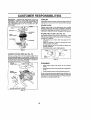
AIR FILTER (See Fig. 17)
Your engine wttl not run properly using a dirty air fiiter_
Clean the {earn pre_Jeaner alter every 25 hours of operation or every season, Service paper cartridge every 100
hours of operation or every season, whichever occurs first
GRADES
Service air cleaner more often under dusty conditions
•
Remove knob(s) and cover.
TO SERVICE PRE-CLEANER
•
Slide foam pro*cleaner
NOTE: Ai'though multi-viscosity oils (5W30, t0W30 etcJ
improve starting _ntoed weather, these multi-viscosity oils
will result tn fncreased oil consumptlon when used above
32°F. Check your engine oil level mere frequently to avoid
posstbte englne damage from running Iow on oil
-
Wash tt in liquid detergent
,,
Squeeze it dry in a clean cloth,
•
Saturate it in engine o_l, Wrap it in clean, absorbent
cloth and squeeze to remove excess ott.
Change the ell after the first two hours of operation and
every 25 hours thereafter or at least once a year if the
tractor is net used for 25 hours in one year.
•
if very dirty or damaged,
•
•
Reinstall pro-cleaner over cartridge.
Reinstall cover and secure with knob(s),
Cheek the crankcase oit level before starling the engine
and after each eight (8) hours of operation Tighlen oil fin
cap/dipstick securely each time you check the oi! Ievef.
TO CHANGE
TO SERVICE
ENGINE OIL (See Figs. 15 and !6)
Determine temperature range expected before oi! change,
All oil must meet AP! service classification SF or SG.
•
Be sure tractor ts on Ieve| sudace°
•
OIEw_Hdrain more freely when warm
•
Catch o}{ in a suitable container,.
•
Remove oil flitcap/dlpstick. Be careful net to altow dirt
to enter the engine when changing o11,
•
Remove drain plug,
19
off cartridge.
and water
replace pro-cleaner.
CARTRIDGE
•
Remove wing nuts and cartridge plate.
•
Carefully remove cartridge to prevent debris from entering carburetor,
•
Ciean cartridge by lapping gently on flat surface.
dirty or damaged, replace cartridge.,
•
Reinstall cartridge plate, wing nuts, precleaner, cover
and secure with knob(s)
If very
CUSTOMER RESPONSIBILITIES
t
IMPORTANT;
PETROLEUM
soLVENTS,
SUCH AS
KEROSENE, ARE NOT TO BE USED TO CLEAN THE
CARTRIDGE
THEY MAY CAUSE DETER)ORATION OF
THE CARTRIDGE
DO NOT OIL CARTRIDGE,
DO NOT
USE PRESSURIZED
AIR TO CLEAN
OR DRY
CARTRIDGE,
MUFFLER
Inspect and replacecorroded muffler and spark attester (if
equipped)as ttcould create a fire hazard and/or damage,
SPARK PLUGS
Replace spark plugs at the beginning of each mowing
season or afler every 100 hours of operation, whichever
occurs first, Spark pfug type and gap selling are shown tn
"PRODUCT SPECIFICATIONS"
on page 3 of this manual
KNOB
PLATE
IN-LINE
FOAM
FUEL
FILTER
(See Fig. 19)
The fuel filter should be replaced once each season.. If fuel
fitter becomes clogged, obstructing fuel flow to carburetor,
replacement is required°
AIR SCREEN
CARTRIDGE
•
Wilh engine cool, remove
sections.
•
Place new fuel filter in position in fuel line with arrow
pointing towards carburetor.
Be sure there are no fuel _ine leaks and clamps are
properly positioned.
immediately wipe up any spilled gasoline
•
filter end plug fuel fine
FIG, 17
ENGINE
COOLING
FINS
(See Fig. 18)
Remove any dust, dirt or oil from engine cooling fins to
prevent engine damage from overheating.. Air guide covers
must be removed. Remove sld e panels and hood (See 'TO
REMOVE HOOD AND GRILL ASSEMBLY" in the Service
and Adjustments section of this manual).
FUEL _._"°
FILTER-
\ /'J
_"_J-----_
/
J
FIG. 19
CLEANING
ENGINE
COOLING FINS
•
Clean engine, battery, seat, finish, etc. of all foretgn
matter°
•
Keep finished surfaces and wheels free of all gasoline,
oii, etc_
•
Protect painted surfaces with automotive
type wax.
We do not recommend using a garden hose to c}een your
tractor unless the electrical system, muIfier, air fitter and
carburetor are covered to keep water out. Water in engine
can result in a shortened engine Iifeo
8
AER GUIDE COVER
FIG. 18
2O
SERVICE AND ADJUSTMENTS
CAUTION:
e
w
e
BEFORE PERFORMING
ANY SERVICE OR ADJUSTMENTs:
Depress clutch/brake pedal fully and set parking brake,
Place motion control lever in neutral (N) position°
Place attachment clutch in "DISENGAGED" position.
Turn Ignition key "OFF" and remove key.
Make sure tile blades and all moving parts have completely stopped°
Disconnect spark plug wire from spark plug and place wire where it cannot come tn contact
with plug.
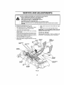
MOWER
(See Fig, 20)
TO
REMOVE
•
Place attachment
,
,,
Turn height adjuslment knob Io lowest selling
',
Lower mower to lls lowest position.
clutch In "DISENGAGED"
position..
Remove retainer spring holding anti-swaybar to chassis bracket and disengage antt-swaybar from bracket°
•
Remove retainer springs from suspension
deck and disengage arms from deck
•
Raise attachment
,
Remove two relainer springs from each front link and
remove links.
forward and remove
belt from engine
•
Slide mower otJtfrom under right sfde of tractor..
IMPORTANT:
tF AN ATTACHMENT OTHER THAN THE
MOWER DECK IS TO BE MOUNTED ON THE TRACTOR,
REMOVE THE FRONT LINKS.
Disconnect clutch rod from clutch lever by removing
retainer spring
,
Slide mower
pulley
TO INSTALL MOWER
Follow procedure described In "INSTALL MOWER AND
DRIVE BELT" in the Assembly section of this manual.,
am_s at
fift to its highest position
CLUTCH
LEVER
RETAINER
SPRING
FRONT
SUSPENSICN
BRACKET
CLUTCH
RCD
SUSPENSION
ARMS
LIFT
CHASS1S
FRONTMCWSR
BRACKET
ANT_SWAY
BAR
RETAINER
SPRINGS
FIG, 20
21
........
;,,,,; ...............................
i ,,,,,i,,,,, ,,,,,,,,,,, i
i,
SERVICE AND ADJUSTMENTS
i
TO LEVEL MOWER HOUSING
FRONT-TO-BACK ADJUSTMENT
(See Figs, 23 and 24)
IMPORTANT: DECK MUST BE LEVEL S{DE-TO-SIDE
iF
THE FOLLOWING FRONT-TO-BACK
ADJUSTMENT IS
NECESSARY, BE SURETO ADJUST BOTH FRONT LINKS
EQUALLY SO MOWER WILL STAY LEVEL SiDE-TOSIDE_
To obtain the best cult{ng results, the mower housing
should be adjusted so that the front is appro×tmately 1/B" to
1/2" lower than the rear when the mower is in its highest
position.
Check adjustment on right side of tractor, Measure distance"D" directly in front and behind the mandrel at bottom
edge of mower housing as shown,
•
Before making any necessaryadjustments,
checkthat
both front _Inksare equat in length. Both links should be
approximately 10-3/8"
•
If links are not equal in length, adjust one link to same
_ength as other link"
,,
To lower front of mower loosen nut "E" on both front
links an equa! number of turns,
•
When distance "D" is 1/8" to 1/2" lower at front than
rear, tighten nuts "F" agatnst trunnion on both front
links
•
To raise front of mower, loosen nut "F'from trunnlon on
both front links. Tighten nut "E" on both front {inks an
equal number of turns.
•
When distance "D" is 1/8" to 1/2" lower at front than
rear, t}ghten nut "F" against trunnion on both front ilnks
•
Recheck side-to-stale adjustmenL
Adjust the mower while tractor is parked on level ground or
driveway,
Make sure tires are properly InfEated (See
' PRODUCT SPECIFICATIONS"on
page 3 of this manual),
If tires a re over or undo dntiated, you will not property adjust
your mower_
SIDE-TO-SIDE
ADJUSTMENT
(See Figs 21 and 22)
•
Ratse mower to its highest position.
.
Atthemtdpotntofbothsidesofmower
measurehetght
from b0ttom edge of mower to groundo Distsnce"A"on
both sides o! mower should be the same or within 1/4"
of each other
•
If adjustment is necessary,
side of mower only.
•
TO raise one side of mower, tighten flitlink adjustment
nut on that side
•
To lower one side of mower, loosen llft link adjustment
nut on that side.
make adjustment
on one
NOTE: Each full turn of adjustment nut will change mower
height about 1/8".
Recheck measurements
after adjusting,
BOTTOMEDGE
OF MOWERTO
BOTTOMEDGE
OF MOWERTO
GROUND
GROUND
MANDREL
FIG. 21
SUSPENSION
ARM
FIG,, 23
BOTHFRONT LINKSMUSTBE EQUALIN LENGTH
LIFT LINK
ADJUSTMENT NLrl*
FIGo 22
NUT "E"
NUT
"F"_
FRONTL|NKS
22
TRUNNION
FIG_ 24
iii
iiii uu
ii
SERVICE AND ADJUSTMENTS
HUUU UUUUUUlUU U
TO
REPLACE
MOWER
DRIVE
MOWER DRIVE BELT REMOVAL
•
I
I
iJu.ullm
tl J _
TO REPLACE MOWER BLADE DRIVE BELT
(See Fig. 26)
BELT
(See Fig 25)
Park the tractor on level surface
Park tractor on a level surface+ Engage parking brake
Disengage attachment c+utch control
Engage parking brake+
,
Remove mowerdrive belt (Bee"TO REPLACE MOWER
DRIVE BELT" in this section of this manual)
,
Remove mower (See'TO
section of this manual)
•
Remove four screws
remove cover+
•
Disconnect secondary clutch rod from pivot rod by
removing retainer spring,,
•
Carefully
Check primary Idler arm and two idlers to see that they
rolate freely.
,,
Remove belt from center mandrel puIley, Idler pulley,
and L.H mandrel pulley,
MOWER DRIVE BELT INSTALLATION (See Fig 25)
•
Install belt in both Idlers Make sure belt is in both belt
keepers at the idlers as shown,
•
Remove any dirt or grass whtch may have accumu+
lated aroundmandrets
and entire upper deck surface.
Cheek secondary idler arm and idler to see that they
rotate freely
•
Remove four screws
remove
from LH
mandret
cover and
cover.
•
Roif beft over the top of L H. mandrel pu}ley+
•
Remove beft from engine pulley
•
Remove belt from idler pulleys
•
Remove any dirt or grass c{ippings which may have
accumulated around mandrels and entire upper deck
surface.
•
•
install new belt onto engine pulley
•
Roll belt Into upper groove of L, H, mandrel puftey
•
Carefut+y check belt routing making sure belt ts in the
grooves correclty and inside bett keepers
Reassemble
•
L+H. mandrel cover
/X
_'
IDLE.
\
PULLEYS
ENGINE
PULLEY
dN 2
from R H+ mandrel cover and
roll belt off R.H. mandrel pulley,
•
Be sure spring is hooked
sway-bar bracket.
•
Install new be_t in lower groove of L H. mandrel pulley,
idler pu+tey, and center mandrel pulley as shown
•
Roll belt over R H+ mandrel pulley
all grooves properly.
•
Reconnect secondary
retainer spring
•
Reinstall R H+ mandret cover:
"
Reinstall mower to tractor (bee "INSTALL MOWER
AND DRIVE BELT" in the Assembly section of this
manual).
•
Reassemble mower drive belt (See '%0 REPLACE
MOWER DRIVE BELT" in this section of INs manual)
SCREWS
COVER,_
REMOVE MOWER" in this
LH+, MANDREL
in secondary
idler arm and
Make sure belt is in
clutch rod to pivot rod with
MOWER
BLADE
ORWE BELT
CENTER
MANDREL
SECONDARY
IDLER ARM
/
I/ "+... [k\+
MOWER
/
DRIVE
BELT BELT
KEEPERS
SPRING
"_
FIG. 25
BWAY SAR
BRACKET
PULLEY
FIG. 26
23
SCREW
SERVICE AND ADJUSTMENTS
i
TO REPLACE MOTION DRIVE BELT
(See Fig. 28)
TO ADJUST BRAKE (See Fig. 27}
Your tractor is equipped with an adjustable brake system
which ismounted on thesldeOfthe transaxieo
tf tractor requires more than six (6) feet stopping distance
at high speed in highest gear, then brake must be adjusted
Park the tractor on level surface. Engage parking brake,
For assistance, there ts a bait Installation guide decat on
bottom side of taft footrest.
•
Depress clutch/brake
•
•
Measure distance between
nut "A" on brake rod,
Remove mower (See "TO REMOVE
section of this manual )
•
Remove upper belt keeper,
•
if distance is other than I-3t4", foosen jam nut and turn
nut "A" until distancebecomes
1-3/4"o Rettghten jam
nut against nut "A".
•
Remove belt from stationary
•
Pull belt slack toward rear of tractor. Carefully remove
bait upwards from transmission input pulley and over
sooting fan btedeso
Pult belt toward front of tractor and remove downward
from around engine pulley.
.
pedaf and engage parking broke
brake operating arm and
Road test tractor for proper stopping distance as stated
above, Readjust if necessary. If stopping distance ts
still greater than six (6) feet in highest gear, further
maintenance is necessary. Contact your nearest authorized service center/department,
•
MOWER" in this
idler and clutching
idler°
•
lnstaII new belt by reversing above procedure.
IMPORTANT:
MAKE SURE UPPER BELT KEEPER IS
POSIT_ONED PROPERLY BETWEEN LOCATOR TABS.
WITH PARKING BRAKE"ENGAGED"
PULLEY
t"
_.,,_LOCATOR
_TABS
CLUTCHING
IDLER
UPPER
STATIONARY"--.
IDLER
KEEPER
TRANSMISSION,,
INPUT PULLEY
DO NOTTOUCHTHIS NUT. IF FUR"_HERBRAKEADJUSTMENTIS NECESSARYCONTACTYOUR NEARESTAUTHORIZEDSERVICECENTER/DEPARTMENT'
FIG, 27
FIG. 28
24
BELT
SERVICE AND ADJUSTMENTS
TO ADJUST
MOTION
CONTROL
TO ADJUST
LEVER
(See Fig, 29)
WHEEL
ALIGNMENT
If steering wheelcrossbarsere not horizontal (left toright)
Whenwheelsarepositionedstraightforward, remove steeringwheeland reassemble per Instructions in theAssemb{y
section of this manual,
The motion control {ever has been preset at the factory and
adjustment should not be necessary.
ff for any reason the motion control lever wll{ not hold its
posilion while at e selected speed, it may be adjusted at the
friction pack located on the right side of transm{ssion
•
STEERING
FRONT WHEEL
TOE-IN/CAMBER
The front wheet (co-in and camber are not adjustable on
your tractor, tf damage has occurred to affect the front
wheel toe4n or camber, contacl your nearest authorized
service center/department,
Park tractor on !evel surface, Stop tractor by turning
ignition key to OFF' position, and engage parking
brake.
°
Adjust motion control lever by tightening adjustment
Jocknut one hail (1/2) turn.
NOTE:
ff for any reason the effort to move the motion
control lever becomes too excessive, reverse the above
adjustment procedure by loosening locknut 1/4 to 1/2 turn.
Road lest tractor after adjustment and repeat procedure if
necessary°
TO REMOVE WHEEL FOR REPAIRS
(See Fig. 30)
•
Block up ax{e secureiy_
•
Remove axle cover, retaining ring and washersto a![ow
wheel removal (rear wheel conta)ns a square key - Do
not lose)
TRANSMISSION REMOVAUREPLACEMENT
•
Repair tire and reassemble.
Shoutd your transmission require removal for service or
replacement, it should be purged after reinstaflatlen and
before operating the tractor. See "PURGE TRANSMISSION" tn the Operation section o! this manual.
•
On rear wheels only: align grooves
and axle Insert square key.
•
Replace washers and snap retaining
axle groove.
•
Replace axle cover,
I
I
I
WASHERS
RETAINING
RtNG
t
1
ADJUSTMENT
LOCKNUT
t
AXLECOVER
FIG, 29
25
in rear wheel hub
ring securely In
SERVICE AND ADJUSTMENTS
i=l,,,H =H
TO START ENGINE WITH A WEAK BATTERY
(see Fig. 31)
I_
'
TO
REPLACE
FUSE
Replace with 30 amp automotive-type plug-in fuse,
fuse ho der s osated behind the dash,.
ateexplostvegases,,
Keepepatks_flame
end smoking materials away from batteries,
wear batteries
eye protection
CAUTION:Always
Lead-acid
generwhen around batteries,
The
TO REMOVE HOOD AND GRILL ASSEMBLY
(See Fig. 32)
•
Raise hood
•
Unsnap headlight wire connector.
•
Standinfrontoftrac|or, Grasphoodatstdes, tilttoward
engine and lift off of tractor.
•
To replace, reverse above procedures..
If your battery' is too weak to start the engine, it should be
recharged.
If "Jumper cables" are used for emergency
starting, IolloW this procedure:
IMPORTANT:
YOUR TRACTOR IS EQUIPPED WfTH A
12 VOLT NEGATIVE GROUNDED SYSTEM, THE OTHER
VEHICLE
MUST ALSO BE A I2 VOLT NEGATIVE
GROUNDED SYSTEM. DO NOT USE YOUR TRACTOR
BATTERY TO START OTHER VEHICLES
HOOD
TO ATTACH JUMPER CABLES •
Connect each end of the RED cable to the POSITIVE
(+) terminal of each battery, taking care net to short
against chassts_
•
Connect one end of the BLACK cable to the NEGATIVE (-} lermtnal of fully charged battery
•
connect the other end of the BLACK cabie to good
CHASSIS GROUND, away from fuettank and battery
HEADLIGHT
WIRE
CONNECTOR
TO REMOVE CABLES, REVERSE ORDER •
BLACKcabIe first from chassis and then tram the fully
charged battery,
•
RED cable last from both batteries.
FIG, 32
ENGINE
"NEGATIVE"i')
"POSITIVE*' (+)
........
TO ADJUST' THRO'I-I'LE
CONTROL
CABLE
(See Fig, 33)
The throttlecentral has been preset at the factory and
adjustment shoutd not be necessary. Checkadjustmenfas
described below before leosening cable, If adjustmentis
necessary, proceed as foJlews:
•
With engtne not running, move throttle control lever to
fast (,_) position,
•
Check that swtvei isagainst side of quarter circle. If it
Is not, ioosen cable damp screw and pull cable back
until swivel is against quarter clrcte. Tighten cable
clamp screw securely
FIG. 31
TO REPLACE
HEADLIGHT
BULB
•
Raise hood.
,
Pull bulb holder out of the hole in the backside of the
grill,
•
Replace bulb in holder end push bulbhotder securely
back tnto the hole tn the bae_tde of the grill.
•
Close hoed.
INTERLOCKS AND
QUARTER
CIRCLE
RELAYS
Loose or damaged wiring may cause your tractor to run
poorly, stop r.Jnntng, or prevent it from starling
•
Check wiring. See electrical W_rtng diagram in the
Repair Parts section of this roan'Jar,
SWIVEL
26
FIG. 33
--
.
_
_._---
i
i,ii
,, ,,,
ii, ll, i,J,,,ll
,
,
,
SERVICE AND ADJUSTMENTS
TO ADJUST CHOKE CONTROL (See Fig. 34)
The choke control has been preset at the factor,/and
adjustment should not be necessary. Check adjustment as
described below before loosening cable if adjustment ts
necessary, proceed as follows:
•
With engine not running, move choke control (located
on dash panel) to ful[ choke d\l) position.
.
Remove air cleaner cover, _ter and cartridge ptate to
expose carburetor choke (see AiR FILTER' in the
Customer Responsibilities section O! this manuaL).
•
Choke shoutd be closed., if it is not, loosen casing
cramp screw and move choke cable until choke is
complete{y closed Tighten casing clamp screw secure[y
•
Reassemble air cleaner.
.
With fhro[f e control _ever _n slow (,,1_) position, hold
throttle iever against Idle speed screw and adjust Idle
speed screw to obtain 1200 to 1400 RPM,
,
Whi_e still holding throttle lever against Idle speed
screw, turn idle mixlure screw in (clockwise) until
engine begins to die and then turn out (counterclockwise) until engine runs rough. Turn screw to a point
m_dway between those two positions.
Continue to hold throttle lever against idle speed screw
and adjust Idle speed screw to obtain 900 to 1200 R PM
Release throttle lever.
•
ACCELERATION
•
CHO|_E
CLOSED
TEST -
Move throttle control lever from slow (_.) to fast (,,_)
position: tf engine hesitates or dies, turn idle mixture
screw out (counlerclockwise)
1/8 turn. Repeat test
and continue to adjust, tf necessary, until engine accelerates smoothly,
High speed stop is factory adjusted,
Do not adjust damage may result.
IMPORTANT:
NEVER TAMPER WITH THE ENGINE
GOVERNOR, WHICH IS FACTORY SET FOR PROPER
ENGINE SPEED. OVERSPEEDING THE ENGINE ABOVE
THE FACTORY
HIGH SPEED SETTING
CAN BE
DANGEROUS. {FYOU THINKTHE ENGINE-GOVERNED
HIGH SPEED NEEDS ADJUSTING, CONTACT YOUR
NEAREST
AUTHORIZED
SERVICE
CENTER/
DEPARTMENT, WHICH HAS PROPER EQUIPMENT AND
EXPERIENCE
TO
MAKE
ANY
NECESSARY
ADJUSTMENTS
LEVER
IDLE SPEED
SCREW
CLAMP
SCREW
FIG. 34
TO ADJUST CARBURETOR
(See Figs. 35 &
IDLE M{XTURE
SCREW
36)
The carburetor has been preset at the factory and adjustment should not be necessary.
However, minor adjustment maybe required locompensate fordiltereneesin
fuel,
temperature, altitude or load. If the carburetor does need
adjuslment, proceed as fol]ows:
LEVER
In general, turning the mixture screw in (clockwise) decreases the supply of fuel to the engine giving a leaner fuel/
air mixture, Turning the mixture screw out (counterclockwise) Increases the supply of fuel to the engine giving a
richer fusI/atr mixture,
FIG,, 35
IMPORTANT;
DAMAGE TO THE NEEDLES AND THE
SEATS IN CARBURETOR MAY RESULT tF SCREW IS
TURNED IN TOO TIGHT
PRELIMINARY
SETTING
IDLE SPEED
SCREW
-
•
Be sure you have a clean air tilter, and the lhrottte
control cable and choke are adjusted properly (see
above),
•
With engine off turn idle mixture screw in (clockwise)
closing It finger fight and then turn out (counterclockwise) 1-1/41o 1-1t2 turns.
FINAL SETTING •
THROTTLE'
LEVER
Start engine and allow to warm for five minutes. Make
final adjustments with engine running end shill/motion
control lever tn neulral (N) position,
27
IDLE MIXTURE
SCREW
FIG,, 36
........................................
,
•
i,,
i
;TORAGE
ENGINE
Immediately prepare your tractor for storage at the end of
the season Or if the tractor will not be used for 30 days or
more,
=
1. =
' =ill=
1, Hiiit, =
,i,,,,
,,"i,
-
:_
gasoline in the tank Inside a building
where fumes may reach an 0pen flame
or
spark, Never
Allow store
the engine
to c001
CAUTION=
the tractor
with
before storing In any enc!osure.
I_
•
=
FUEL SYSTEM
J
.
, =-, ,,=,,
IMPORTANT:
IT IS IMPORTANT TO PREVENT GUM
DEPOSITS
FROM FORMING
IN ESSENTIAL
FUEL
SYSTEM PARTS SUCH AS CARBURETOR, FUEL FILTER,
FUEL HOSE, OR TANK DURING STORAGE.
ALSO,
EXPERIENCE INDICATES THAT ALCOHOL BLENDED
FUELS (CALLED GASOHOL OR USING ETHANOL OR
METHANOL) CAN ATTRACT MOISTURE WHICH LEADS
TO SEPARATION AND FORMATION OF ACIDS DURING
STORAGE,
ACIDIC GAS CAN DAMAGE THE FUEL
SYSTEM OF AN ENGINE WHILE IN STORAGE
TRACTOR
Remove mower from tractor for winter storage,
When
mower is to be stored for a period of time, clean it thoroughly, remove eli dirt, grease, leaveS, etc, Store in a
clean, dry area.
•
Clean entire 1rector (See"CLEANtNG"tnthe
Responsibilities section o! 'this manual).
•
Inspect and replace be.Its If necessary (See belt replacement Instructions in the Service and Adjustments
section of this manual)
•
Lubricate as shown tn the Customer
section of this manual
•
Be sure that al_ nuts, bolts end screws are securely
fastened. InSpect moving parts for damage_ breakage
and wear, Replace tf nece_aryo
,
Touch up all rusted or chipped paint surlaces;
ligh'tly before painting,
Drain'the
•
Start the engine and let it n_n until the fuel lines and
carburetor are empty,
•
Never use englne or carburetor cteanerproducts
fuel tank or permanent damage may occur.
•
Use fresh fuel next season,
Customer
ENGINE
sand
FuIIy charge the battery for storage.
After a period of t_me in storage, battery may require
recharging.
o
To help prevent corrosion and power leakage during
long periods of storage_ battery cables should be
disconnected and batlety cleaned !horo?ghly (sea"TO
CLEAN BATTERY AND TERMINALS
In the Customer Responsibilities section of this manual).
tn the
OIL
Drain 0H(withenginewarm) and replacewith cleanengine
oil
(See "ENGINE" in the Customer Responsibilities
section of thismanual)
BATTERY
•
fueltank,
NOTE:
Fuel stabilizer is an ecceplab_e alternative in
minimizing the formation of fuel gum deposils during storage. Add stabtJizer to gasoline in fuel tank or storage
container, AIways follow the mix ratio found on stabilizer
container.
Run engine at least 10 minutes after adding
stabtltzertoallowthestabtllZertoreachthecarburetor,
Do
not drain the gas tank and carburetor if using fuel etabIliZerr
Responsibilities
•
•
•
CYLINDERS
After cleaning, leave cables disconnected and place
cables where they cannot come in contact with battery
termtnalso
•
Remove spark plug(s).
•
Pour one ounce of oil through
cylinder(s)
•
Turnignltion keyto"START"
to distribute oil
,'
Replace with new spark plug(s)
spark plug hole(S) into
position for a few seconds
OTHER
•
Be sure ba[tery drain tube is secorely attached,
•
Do not store gasoline from one season to another.
•
if battery ts t'emoved from tractor for storage, do not
store battery directly on concrete or damp sudaces.
.
Replace your gasoline can if your can starts to rust,
Rust and/or dirt in your gasofine will cause problems
,,
if possible, store your tractor indoors and cover it to
give proteclton from dust and dirt.
•
Cover your tractor with a suitable protective cover that
does not retain moisture, Do not use plastic. Plastic
cannot breathe which allows condensation to form and
will cause your traclor to rust.
IMPORTANT; NEVER COVE R TRACTOR WH_LE ENGINE
AND EXHAUST AREAS ARE STILL WARM,
28
TROUBLESHOOTING
POINTS
PROBLEM
CAUSE
wig nat stoat
1
2
3
4
5
6
7
Outof fuel
Engine not"CHOKED" properly
Engine flooded
Bad sparkplug
Dirty air fitter
D_r_yfuel niter
Water In fuel
1
2
3.
4
5.
6
7
8
9
Loose or damaged wJdng
Cmburalor out of ad_uatmanl
g
9
10
CORRECTION
Engine valves uul of edJuslment.
10
Fill fuel t_nk
See "TO START ENGINE" in Opeteltoo section.
Wait severalminutes before attempting la start
Replace spark plug.
Clean/rapists aJrfiller
Replace fuel litter.
Drain lust tank and carburetor, rel_11tank with fresh
gasolineand replace fueltiller
Check ellwiring.
See "To Adjust CarSuretor" InService Adjustments
section,
Coolant eo euthodzed service cenlurldepadmenl
i,
1
2
3
4
5.
6
7
Dldy air filter
Bad spark plug
Weak or deed battery
Didy fuul filter
Stale atdidy fuel
Lnoseordemagsdwidng
Carburetor outOfadjustment
I
2
3
4
5
G,
7
8
Engine valves out of adtustmanl
8
Ctean/reptaco alr lifter
Replace spark plug,
Recharge or replane battery
Replace fuel iiIler
Drainfueltankand refill
withfreshgasolfne
Chuck ell wldng.
See "To Adjust Carburetor" In Set,so Adjustments
section.
Contact en authorized
service canlarldepadmenl.
Engine will not turn over
t
2
3
4
5,
6
7
B,
9
Clutch/brake pedalnoidepressed
Attachment dutchla engaged.
Weaker deadbaltary
Btown fuse
Corrodedbelier/tem_inals
Loose or damaged wiring
Faulty ignition ewttch
Faulty solenoidorstarlet
Fat@/operator presence ewitch(e_)
t
2
3
4
5
5
7
B
9
Depress clutchi'brake
pedal
Disengage attachment clutch
Recharge or rapists batlury
Replace lass,
Cfaun batteP] tem'-JnaJs
Check HI wiring
Cheek/replane tgntSon switch
Checl.'Jreplacesolenoid
or starter
Contact an eulborized service eanteddepadment
Engine clicks but will not
start
I
2.
3
4
Weekordeadbattory
Corroded baflarytarmlnsts
Luoso or damaged widng
Faulty solenoid or starter
t
2
3.
4
Recharge or replace battery
Clean battery
terminate
Check allwiring
ChuckHeplece .5oIenc4dor slarler
Leas
t.
2
3
4
5
6
7
8
g
Cutting leo much grass/too feel
Throttle
In'CHOKE" position.
Build*up ofgrass- leavesand trash under mower.
D_dyair filler.
Low oil level/dfity ulI
Fauliy spark plug
Dldy fuaifilter
Sfale or dilly fuel
Water In fuel
1
2
3
4
5
6.
7
8
g
Set In _Higher Cut" position!reduce speed
Adjust lhroltla controI
Clean underside of mower housing
Claan/replace
alt filler
Check oil levellchanga oil
Clean end regap or changa spark plug
Replace fuel filter
Drain tuai lank and rslli! with fresh gasoline.
Drain fuel tankand carburetor, refill lank with fresh
gasolineend replacefuelfiller.
Connect and lighten spark plug wire.
Clean engine air acleen/fIns
CluerJreplace muffler
Check elf wtrtng.
See %0 Adjust Cmbureto,'in Ss_ce Adjustment_
sectlon.
Contact en authorized eurAeeeentoddopellment
of power
Excess|vo vibration
10
11
t2,
13
!4
Sped( ptug wlre Iuose
Dirty engine air screen/fins
Dldylcfogged
muffler,
Loose or damaged wiring
Carburetor out of adjustment
1O
11.
!2
t3
14
15
Engine vanes out of adjustment
15
t
2
3.
Worn, bent or loose blade
Bent blade mandrel
loosoldamagad pall(s)
29
1
Replace
2
3
Replace blade mendrat.
Tighten loose pad[s)
Replace
blade
Tighten
blade bolt
damaged
pads
u,ui
TROUBLESHOOTING
u Hmll i, H,
PROBLEM
1_ LUJ,u ,_uu_J
POINTS
,,, ,, ,, ,,,,,,,,,,
CAUSE
CORRECTION
Engine continues to run
when operator teaves seat
with attachment clutch
engaged
1
Feutiy operator-safety presence eonlrol system
t
Check wiring, swllches end connections. If not
corrected, contact
an authorized service conterl
dsparlmonL
PooFoat-unevsn
1
2
3
4
Worn, ben! or tease blade
Mower deck net level
Buildup of grass, ]eaves. and trash under mower
Bent blade n_andrel
5
Clogged mower deck vent holes tram buitdup of
gross, leaves, and trash around mandrels
t
2
3
4
5
Replace blade Tighten bladeboil.
Lava{ mower deck.
Clean underside of mower housing
Replace blade mandret
Clean around mandrets Io open Vent holes
I
2
3
4
Obstruction in clutch mechanism
Wom/darnaged mower drive belt
Frozen Idler puIEoy,
F{ozeo blade mandrat
1
2
3
4
Remove obsi_Jotien.
Replace mower ddve belt
Reptace idler pultey
Replace btado mandrel
Mower blades wig not
rotate
Poor grass
discharge
Headlight(s} not working
{if so equipped)
Battery wgl not charge
t
2
3
4
5
6
7
B
£,
10
11-
Engino speed too slow
Travel speed too fast
War grass
Mower desk net level
Low/uneven tire air pressure
Worn, bent or !ease blade
Buildup of grass, leaves and trash under mower
Mower drive be_tworn
8lades tmpropody tnsiatiod
improper blades used,
Clogged mower deck vent holes from buildup of
grass, leaves, and trash sroued mandrels
I
2
3
4
5
6
7
8
g
10
11
PLacefhro_tie sonlro! tn *FAST" position.
Shtlt to sfower speed,
Aliow grass to dry before mowing
Level mower deck
Check tires for proper s# pressure.
Repines/sharpen blade Ttghlen blade bolt
Clean undeleide of mower housing
Replace mower drive bel{
Reineta_Iblades shmrp edge down
Replace wlih blades iIsied In this manual
Clean around mondra_s |o open vent holes
"t
2
3
4
5
SwitCh ts "OFF"
Bulb(e)
burnedout
Foully tight switch
Loose or damaged wiring
Blown fuse
1
Turn switch
2
3
Replace bulb(e)
Checldreplace
light owlish
4
5
Check wldng and connections
Replace fuse
I
2
3
4
Bad batlory coil(s)
Poor sable connections
Faulty regulaler (if so equipped)
FBUtbi alternator.
1
2
3
4
Repines beilery
Check!clean all connections
Replace regaiator
Reptace alternator
, Hi
,
,
i
"ON"
i
Loss of drive
t
2
3
Freewheel c0ntm{ tn "disengaged" position
Motion ddve bait were, damaged, or braken.
Air trapped In transmission during shipment
or servicing
I
2
3
Place freewheel eoot_oi in *engaged" position
Repress motion drive bait
Purge transmission
Engine "backfires"
when turning engine
"OFF"
I
Engine throttlecontrol nol sef Bt "SLOW*
1
Move Lhrottlecontrol ]o"SLOW" position and allow
to Idle for 30 seconds befara etopplng engine
position for 30 seconds before stopping engine
3O
TRACTOR
- - MODEL
NUMBER
917.258670
SCHEMATIC
BATTERY
FUSE 30 AMP
AMMETER
{OPTIONAL}
aLACK
SOLENOID
IGNITION
SWITCH
f
(CLUTCH OFF)
GROUNDSNG
CONNECTOR
HEADLIGHTS
SHOWN
NOTE
YObRTRACTQRiS
EQUIPPED wITH A SPECIAL
ALTERNATOR SYSTEM,
THELIGHTS ARE NOT
IGNITION
SWITCH
•
©
CONNECTED
TO THE
NON-REMOVABLE
REMOVABLE
BATTERY, BUT HAVE THEIR
CONNECTIONS
CONNECTIONS
/-)
OWN ELECTRICAL SOURCE/
BECAUSE OF THIS, THE
BRIGHTNESS
OF THE LIGHTS
WIRING INSULATED
CLIPS
WILL CHANGE WITH ENGINE
NOTE: IF WIRING INSULATED
SPEED. AT iDLE THE LIGHTS
CLIPS WERE REMOVED FOR
WILL DIM. AS THE ENGINE IS
SERVICING OF UNIT, THEY
SPEEDED UP, THE LIGHTS
SHOULD BE REPLACED
TO
WILL BECOME THEIR BRIGHTESTo
PROPERLY
SECURE YOUR W_RING
31
REPAIR PARTS
TRACTOR
- - MODEL
NUMBER
917.258670
ELECTRICAL
26
11
i 1
J
32
REPAIR PARTS
TRACTOR
--
MODEL
NUMBER
917_258670
ELECTRICAL
KEY
NO,
/
2
3
4
6
7
8
9
10
tl
I2
16
19
20
21
22
24
26
26
28
29
30
31
32
33
40
41
42
43
44
45
52
55
_0
PART
NOo
144926
74760412
ST0551025
STD55i125
STD541025
7697J
7503J
109596X
145211
150109
145769
153664
STD551125
73350400
147430
4i62J
4799J
146146
1o6624X
145491
t21305X
140301
_24211X
141226
109310X
156442
71110406
131553
145673
73640400
121433X
14194O
17490568
140413
DESCRIP_ON
Battery
Bolt, HeX 1/4-20 x 3/4
Washer 9/3_x 5/8 x 16 Gauge
Washer, Lock 1/4
Nul, Hex 1/4-.20
Tube
Tr_,y Battery
Clamp,Hose
Bolt, Btr Front I/4"20 x "t-i/2
Holdd0wn Battery Front Mount
Nut, Push Nylon Battery Front 1/4
SWilch interlock Push-ln
Washer, Lock 1/4
Nut, Hex, Jam 1/4-20
Harness, Light Socket (w14152J)
LightBulb
cable, Battery
Gable,Battery
FUse
Cable, GroUnd
Switch_ Seat
Switch, Ignition 4 Position
Nut IgnltfOn
Cover, Ignition Switch
Key, Molded, C,raflsman
HarneSs, Ignition
Bolt Bit< Fin Hex 1/4-20 UNC x 1/2
Cover, Terminal
Sotenoid
Nut Keps Btk Hex 114-20 UNC
Ammeter Rectangular 6 Amp
protection Wire Loop (Hour Meter)
Screw Thcftol 6/i6-16 x 1(2
Harness EngtMe B&S/Tee Dual
NOTE,, All componentdimensions given in U.S. tnChe_
1 Inch = 25,4 mm
33
REPAIR PARTS
.TRACTOR
- - MODEL
NUMBER
917.258670
CHASSIS AND ENCLOSURES
28
58
12
_ Aolil
_,o
6O
142
3
74
14
3
34
REPAIR PARTS
TRACTOR
- - MODEL
NUMBER
917.258670
CHASSIS AND ENCLOSURES
KEY
NO_
t
2
3
PART
NO.
153871
140356
17490612
4
5
9
10
It
I2
13
14
STD551025
155272
150156X011
STD533710
155927
145660
155936
17490608
!7
18
20
23
25
26
t44963X558
126938X
156437
124028X
19131312
STD541437
28
29
30
31
37
38
145196X558
145200
15t287X558
139976
17490508
139686
39
139887
51
52
53
54
73800400
19091416
145201
17O3O814
55
57
58
60
64
74
122
123
140
142
143
144
145202
STD552507
140847
721406O6
154798
STD541437
157301
152927
158418
156095
154986
154207
NOTE:
DESCRIP_ON
Chassis
Drawbar
Screw, Thd., Roll 3/846 x 8/4 Type
TT
Washer 13/32 x3/4x 16 Gauge
Bumper Hood/Dash
Dash, SIIkscreened
Bolt, Carriage 3/8-16 x 1
Panel, Dasll, LH
Clip Tinnerman Grille P/L
Panel, Dash, HH
Screw, Thd,, Roll. 3/8-16 x 1/2 Type
TT
Hood Asssmbty
Bumber Hood
Plate Mtg Battery Fuel Tank
Bushing, Snap, Nylon, Fuet Line
Washer 13/32 x 13/18 x 12 Gouge
!_ocknut, Hex, with Insert 3/8-16 UNC
Grille, W/Clips M8-558
Lens, Gdt!e
Fender/Footrest
Bracket, Fender/Support
Screw, Thdrol 5116-18 x 1t2 TYT
Pivot Bracket Assembly, LH, Mower,
Hear
Pivot Bracket Assembly, RN, Mower,
Rear
Nut Lock W/Insert 1/4 - 20 UNC
Washer 9/32 X 7/8 X 16 Ga.
Bracket GdlIe Ptckoff LH
Screw, Hex Head, Bpidedock #8 x 7/6
AB
Bracket Gdlle Plckoff RH
BoEt FtnHex t/4 .-20 UNC X.75
Ak Duct PiL 18HP B&S Opp. Twin
Bolt Rdhd Sqnk 3/8-16 UNC x 3/4
Dash Lower STLT
Nut Crownlock 3/8-t6 UNC
Bracket, Shift STLT
Screw TT #I0-32,5,3/'8
Flange
Bracket Suspension Front
Plale Reinforcement STLT
Backrest Swaybai Chassis
Bracket Footrest STLT
All component dimensions
1 Inch = 25 4. mm
35
given In U.S, Inches
REPAIR
PARTS
TRACTOR
- - MODEL
DRIVE
36
NUMBER
917.258670
REPAIR
PARTS
TRACTOR
--
MODEL
NUMBER
9t7.258670
DRIVE
KEY
NO_
1
2
3
8
t0
15
16
16
19
21
22
24
25
26
27
28
29
30
31
32
34
35
36
37
38
39
40
41
42
47
48
49
50
5t
52
53
55
56
57
59
61
PART
NO."
150071
142431
143995
154792
STD561210
74490544
STD541431
STD523710
STD541437
130564
145627
73350600
!06888X
STD551037
STD561210
145204
124236X
130507
127275X
74760512
155071
120183X
19211616
1572H
123674X
STD523727
4470J
154777
19131312
127763
154604
!23205X
STD523716
STD54t437
STD541431
105710X
105709X
STD5237t2
140294
140312
17490612
KEY
NO,
DESCRIPTION
Transaxle (See Breakdown)
Hydro Gear Mode[ No. 310-0650
Spring, Return, Brake
Pulley, Transaxle
Rod Shtft Fender STLT
Pin Cotter 1/8xl
CAD
Boit Hex Flghd 5/16-15 Gr, 5
Nut Lock HexW/tns.
5116;18 Unc
Bolt Ftn Hex 3/8;16 Unc x I Gr. 5
Nut Lock Hex WfWsh 3/8-t8 Unc
Knob, Deluxe 1/2-13
Rod, Brake Hydro
Nut, HexJam
3/8-16 Unc
Spring, Brake Rod
Washer
Pin Cotter !/8 x3/4 CADRod, Parkfng Brake
Cap, Parking Brake
Bracket, Transaxle
Keeper Belt Lh
Bolt Hex Hd 5/16-18 Unc x3/4
Shaft, Foot Pedal
Bearing, Nylon
Washer
Pin, Rotl
Pulley, idler, Fiat
Bait
Spacer, Spl}l
Keeper, Bettldter
Washer 13/32x 13/16x i2 Gauge
Pu{Isy, _dier, V-Groove
Be[IcrankAseembly
Retainer, Beit
Boit
Nut Crowntock 3/8-16 UNC
Nut, Crownlock 5/16.t8 Uno
Link, Clutch
Spring, Return, Clutch
Boll Flex 3/6-16 x t-1/4
V-Bait, Ground Ddve
Keeper, Center Span
Screw ThdroL 3t6-16 x 3/4 Ty, TT
62
63
64
65
66
71
72
73
74
75
76
77
79
81
82
83
84
86
87
88
89
90
91
92
93
94
95
96
97
98
100
102
103
404
105
106
116
118
121
124
PART
NO_
8883R
140186
71170764
STD551t43
154776
140158
19132012
156347
121199X
121749X
STD581075
123583X
121748X
156046
123782X
19171216
140548
71206
19212016
12000008
154882
124346X
74760536
74780524
142564
140462
144643
4497H
140469
73510600
19111216
141322
73940800
140156
71070516
74780520
72110610
154774
154419
156470
NOTE:
'37
DESCRIPTION
Cover, Pedal
Pulley, Engine
Bolt Hex 7/16-20 x 4 Gr 5
Washer
Keeper Bait Engtne Full-Proof
Strap Torque Lh Hydro 18/20" T
Washer 13/32 x 1-1/4 x 12 Ca..
Strap Torque Rh Hydro 0650
Spacer, Spli_
Washer 25/32 x 1_1/4 x 16 Gauge
E-Ring
Key, Square
Washer 25/32 x 1-5/8 x 16 Gauge
Shaft Asm. Cross Hydro 20' Tires
Spring Torsion T/A
Washer 17/32 x 3/4 x 16 CaRod, Tie Hydro 20" Tires
Bushing Rod Stdg 629/832 ID
Washer 21/32 x t-1/4 x 16 Ga.
Ring KJIp #5304-62
Console, Shilt
Nut Se{l_Thd Wsh-hd I/4 Zinc
Bolt Fin Hex 6116-18 x 2-1/4
Bolt Fin Hex 5/6-18 Unc x t_1/2
Line Fuel Hydro 4"
Fan, Hydro 7"
ControfBypass
Hydro 20" Tires
"Retainer Spring I ZinclCad
Keeper Bolt Rh Hydro 0750, 15/20"
Nut Keps Hex 318-16 Unc
Washer 11/32 x 3/4 x t6 Ca,
WasherBellvii_e .501D x 1.50D
Nut Hex Jam Toplock 1/4-20 Unf
Arm, Control Hydro
Screw Cap Hex 5/16 x 18 x "_
Bolt Fin Hex 5/16-18 Une x 1-1/4
Bolt Carr 3/8d6 x 1_25
Spacer Bellcrank
Myliner Clutching STL
Guide Belt RH Englne
All component dimensions
1 inch = 25.4 mm
given In U_S. inches
REPAIR PARTS
TRACTOR
- - MODEL
NUMBER
STEERING ASSEMBLY
6_
27
.._-,-_"17
o+.+-+i+++_+_+..
++ ,,_+.
\
Z+.°+/
__._
'\
\ ++.++,.d+
--'=
+_+...+-,_..-
38
917.258670
REPAIR PARTS
TRACTOR,
- MODEL
NUMBER
917.258670
STEERING ASSEMBLY
KEY
Nee
1
2
3
4
5
5
7
8
9
10
11
13
15
17
18
19
20
21
22
23
25
28
27
25
29
30
32
36
37
38
39
40
4t
42
43
44
46
47
5t
54
62
63
65
66
67
68
PART
NO.
139768
154427
154422
154423
6266H
121748X
19272016
12000029
3366R
158438
STD551137
154779
73901000
156546
57079
124035X
126684X
STD551125
71100410
127501
I54406
126847X
136574
19131415
17490612
STD561210
130465
155099
152927
139789
.
19133808
7610H
1007IIL
145054
121749X
153720
121232X
6855M
73800500
74780520
158594
74780616
154780
154404
74781044
154429
NOTE:
'DESCRIP_ON
Wheel Steering Std Black
Axle Asm Front
Spindle Asm Lh
Spindle Aem Rh
Bearing Race Thrust Harden
Washer 25/32 X 1 5/8 X 16ga
Washer 27/32 X 1 1/4 X 16 Ga
Ring Ktip #t5304-75
Bearing Col Strg Blk
Link Drag Extended Slamped
Washer Lock Hvy Hlcl Spr 3/8
Bearing Axle ST1,T/GT
Locknut Flange 5/8-11 UNC
Shaft Asm Strg Private Label
Washer Thrust 515x 750x 033
Support Shaft
Washer Shim t/4 X 5/8 X 062
Washer Lock Hvy Helicat 1t4
Screw Cap Sskt Hd Phes & O1t
Shaft Asm Pittman
Bracket Steering
Bushing Rod Tie BIk Lt
Gear Sector
Washer 13/32 X 7t8 X 16ga
Screw Thdrol 3/8-t6x3/4 Ty-tt
Pin Cotter !/8 X 3/4 Cad
Rod Tie Wire Form 19 75 Mesh
Bushing Strg 5/8 Id Dash
.
Screw TT #10-32x5x3/8 Flange
Insert Cap Slrg Wheel Std Blk
Washer 13/32 X 2-3t8 X 8 Ga
Nut Lock Center 3/8-24 UNF
Adaptor Wheel Strg
Boot Shaft Steedng
Waeher25t32
X 1 1/4 X 16 Ga
Extension Steedng Non-Adjust
Cap Spindle Fr Top Blk
Fttttng Grease
Nut Lock Hex W/Ins 5/16 -18 UNC
Bott Fin Hex 5/16 - 15 UNC X 1 -1t4
Kit, Steedng Assembly
Bolt Fin Hex 3/8-!6unc x 1 Grr5
Spacer Axle
Bearing Arm Ptttman
Bo_! Fin Hex 5/8-I 1 UNC x 2-3/4
Axle Brace
All component dimensions
1 Inch = 25 4 mm
39
g_ven in U.S. inches
REPAIR PARTS
TRACTOR
- = MODEL
NUMBER
917.258670
ENGINE
13
32
39
31
34
40
_33
29
OPTIONAL
EQUIPMENT
Spark Arrester
40
REPAIR PARTS
TRACTOR
--
MODEL
NUMBER
917.258670
ENGINE
KEY
NOo
PART
NO.
1
2
151273
17720410
3
_ ......
4
5
6
7
8
!0
11
12
13
t4
15
16
17
23
25
26
27
29
31
32
33
34
35
37
149723
144069
144068
138129
150176
145552
STD551125
STD522607
272250
13280336
13200300
STD551237
17490624
156123
145996
73920600
152927
137180
153630
155971
123487X
106082X
17490512
8543R
39
4O
4I
8t
109227X
3645J
139277
128861
NOTE:
DESCRIPTION
Control Throt Paddle 32 22
Screw Hex Thd Cut 1/4-20X5/8 T
Engine (See Breakdown) Briggs
Model No, 42E707-1631-01
Muffler Exhaust
Exhaust Aam, Left
Exhaust Asm. Right
Ctamp Tube Double Engine
Bolt 5/18 - 18 UNC X 3/4 W/Seres
Heat Shteld LI
Washer Lock Hvy. Helical 1/4
Bolt Fin Hex 1/4-20 x 3/4
Gasket Muffler
Ntppfe Pipe 4-1/2"
Elbow Std 90 Degree 3/8-18 Npt
Washer Lock Ext Tooth 3/8
Screw Thdrol 3/8_16x1-1/2 Tytt
Shield Browning
Cont_o! Choke
Nut Keps 3/8-24 Unf
Screw TT #10-32 x 5 x 3/8 Flange
Arrestor Spark
Tank Fuel 3 50 Rear
cap Fuel Guage STt.T
Clamp Hose Blk
Spacer Pad
Screw Thdro15116-18 x 3/4 T_q"
Line Fuel
Plug O11Drain (Order From Engine
Manufacturer)
Pad Idler 1,75 x 75 x ._)6
Bushing
Stem Tank Fuel
Nut, Flange 1/4-20 Startei" Nut
All component dimensions
1 inch = 254 mm
41
given in U.So Inches
REPAIR PARTS
TRACTOR
- - MODEL
NUMBER
917.258670
MOWER LIFT
5
49
3O
3
\
4
13
13
20
13._
31_
32
t9
42
REPAIR PARTS
TRACTOR--
MODEL
NUMBER
917.258670
MOWER LIFT
KEY
NO.
1
2
3
4
5
6
7
6
10
11
12
13
15
16
t7
18
19
20
23
24
25
26
27
26
29
30
31
32
49
PART
NO.
136973
145117
105767X
12000002
19211621
120183X
125631X
122365X
122512X
139865
139866
STD624008
127218
73350800
130171
73800500
139868
STD624008
110807X
19131016
2876H
76020308
126971X
73350600
138057
150233
140302
73540800
145212
NOTE:
DESCRIPTION
Wire Assy,, lnher, with Plunger
Shaft Asm. Lift
Pin Groove
E Ring #5t33-62
Washer 21/32 x 1 x 2t Ga.
Bearing Nylon
Grip Handle Fluted
Button Prunger Read
Spring Cprsn
Link Lift Lh Fixed Length
Link Lift Rh Fixed Length
Retainer Spring,
Link Front
Nul;Jam Hex 1/2-13 Unc
T_nnion BIk Zinc
Nut Lock WPCVsh 1/2-13 Unc
Arm Suspension Rear
Retainer Spring
Nut Spring
_...
Washer 13/32 x b/u × 18 Ga.
Spring 2-1/8"
Pin cotter 3/32 x 1/2
Rod Adj,. Lilt
Nut HexJam 3/8-16
Knob lnfo 3/8-16
Trunnion fnfin_ Height
Bearing, P_vot, Lt[t, Special
Nut, Orownlock 3/8-24
Nut Ftange Lock
Air component dimensions given in U,S. inches
1 inch = 254 rnm
43
REPAIR
PARTS
TRACTOR
-- MODEL
NUMBER
917.258670
MOWER DECK
83
41
75
62 _
76/
78
32
22
102
104
REPAIR
PARTS
TRACTOR
- - MODEL
NUMBER
917.258670
MOWER DECK
KEY
NO+
PART
NO.
I
3
5
6
8
9
10
156948
138457
4939M
130832
850857
10030600
140296
It
t2
t3
152443
129895
137553
14
15
16
18
19
20
21
22
23
24
25
26
27
28
29
30
31
32
33
34
35
36
37
38
39
40
41
42
43
44
45
46
47
48
49
50
51
137152
110485X
140329
72140508
132827
145055
73680500
134753
131267
105304X
123713X
110452X
157788
19111016
131491
138776
129963
153531
137266
144945
17490628
19131316
131494
156086
144917
137273
17490620
122052X
144949
133943
145059
137729
144959
139573
73680600
72110612
153390
KEY
NO,
DESCRIPTION
DeckAsmo, Mower 46"
Bracket Astor, Sway Bar
Retainer Spring
Arm, Suspension, Rear (Sway Bar)
Bolt, Patched 3/8-24 x !-1/4 Gr. 8
Washer, Lock Hvy., Unptated 3/8
Washer, Hard Blade, Mower
Vented
Blade, 46" Mower Deck
Bearing, Be{I, Mandrel #6204
Shaft Asm+ w/Lower Bearing
(Includes Key No. t2)
Housing, Mandret
Bearing, Ball, Mandrel
Stripper, Mower Round
Bolt, Carriage 5116-16x5/8
Bolt, Hex Head, Shoulder 5t16+18
Baffle, Vortex Mower 46"
Nut, Crownlock 5116-t8 UNC
Stttfiner, Bracket
Bracket, Deflector
Cap, Sleeve
Spring, Torsion, Deflector
Not, Push
Shield, DeftectorMower
Washer 11/32 x 518 x 16 Ga+
Rod, Hinge
Screw, HexHead, Thdrofl
Washer, Spacer Mower Vented
Pulley, Mandrel
Nut, Fig. Top Lock Cntr. 9116
Anchor, Spring Deck 46"
Screw, Thdroll 3/8-16 x 1-3/4 Tytt
Washer I3/32 x t3/16 x 16 Ga_
Pulley, Idler, Flat
Keeper, Belt, Idler
Pulley, Idler, Ddven
Spring, Secondary 44/46t50 Vent
Screw, Thdroll 3t8+16 x 1_114 Tytt
Spacer, Retainer
Arm, ldlerSecondary
Washer, Hardened
Cover, Mandrel Deck
Screw, Thdroll
1t4-20 x 5/8
V+Belt, Mower, Secondary
V-Belt, Mower, Primary
Nut, Crownleck 3/8-16 UNC
Bolt, Carriage 3/8+16 x 1-1/2 Gr, 8
Washer, Felt
52
53
54
55
58
59
60
61
62
63
67
68
69
70
71
72
73
74
75
76
77
78
79
80
8t
82
83
84
87
92
94
101
162
103
104
105
106
116
117
t18
119
126
127
- --
PART
NO,
156493
19131312
74780616
72140608
156488
157034
156722
139888
131870
156473
74760512
156487
73350600
142028
133551
19111116
76020412
156474
127847
154809
127845
127498
15370t
121748X
12000029
4497H
129803
149846
158373
73800600
149846
145579
71161010
10071000
tg061216
130758
2029J
137644
133957
73930600
19121414
156472
146763
157112
DESCRIPTION
Pulley, idler, 97 46 Pd. Drive
Washer, 13132 x 13/16 x 12 Ga_
Bolt, Fin. Hex 3/8+16 x 1 Gr. 5
Bolt, RDHD S_nk. 8/8-16 UNC x 1
Link, Brake 46 Mech
Guide, Belt 46" Mower
Arm Assm+ Brake 46"
Bolt, Shoulder 5/18-18 Type TT
Spring Return
Bracket, Clutch Rod Pivot
Bolt, Hex Head 5tt6-18 x 314
Rod, Clutch
Nut, Hex Jam 3/8+t6 Unc
Trunnion, Adj 94
Rod, Pivot with Ntbs
Washer 11132 x 11/16 x 16 Ga.
Pin, Cotter 1/8 x 3/4
Link, Clutch 46+' Mech.
Arm, Clutch Secondary
Lever, Assm+ Clutch Primary
Keeper, Spring
Bushing, _747 OD x .794 ID.
Spring, Mower Clutch
Washer 25132 x 1-518 x 16 Ga.
Ring, Clip
Retainer Spdng 1"
Bolt, Shoulder 3/6+16 Unc
Knob, Custon Oval
Bracket, Extension
Locknut, Flex, w/Insert 318-16 UNC
Knob Custom Oval
Cover, Mulching
Screw
Washer, Lock #10
Washer
Latch Asm+ Bagger
Nut, Weld
8oil, Shoulder
Gauge Wheel Wide
Nut, Centerlock 3/8+16 UNC
Washer 3/8 x 7t8 x 14 Ga°
Arm, Idler, Deck 46" Mech+
Pulley, Idler, V-Groove Dim. 4.25
Deck Complete (Std. Deck-Order
separately mutcher plate and gauge
wheel components Key Nos. IO1t06 and 116-118)
--+
143651
Mandrel Assm. Service
NOTE: All component dimensions given in US inches
I inch = 25 4 rnm
43
REPAIR
PARTS
TRACTOR
- - MODEL
NUMBER
917.258670
SEAT ASSEMBLY
KEY
NO.
PART
NOo
1
2
3
4
5
6
7
8
9
10
I2
140123
140551
74760616
19131810
145008
STD541437
124181X
t7490616
19131814
155925
121246X
DESCRIP_ON
KEY
NO.
Seat
Bracket Phi Pivot Seat (blk)
Bolt Fin Hex 3/8-18 UNC x 1
Washer Fiat13/32 x1 xl0Ga
Cllp Push-In
Nut Lock HexW/ins 3/9.16 UNC
Spring Seat Cprsn 2 250 Slk Zi
Screw 3/8-16xl
Washer 13/32 x ! x 14 Ga
Pan Pnt Seat (bfk)
Bracket Pnt Mounting SwJloh
13
t4
16
16
!7
21
22
23
24
25
26
PART
NO_
121248X
72050411
134300
I21250X
123976X
153236
STD541431
74780814
19171912
127018X
STD551150
NOTE:
46
DESCR|P_ON
Bushing Snap Blk Nyl 50 ld
So}! Rdhd Sht Nk t/4-20xt.,3/B
Spacer Split 28 X 96 Zinc
Spring Cprsn 1 27 Blk Pnt
Nut Lock 1/4 Lge Fig Gr 8 Zinc
Bolt Shoulder 5/16-18 Unc
Nut Lock Hex W/Ins 5/16-18
Bolt Fin Hex 1/2-13 X 7/8 Gr8
Washer 17/32 X 1-3/18 X 12 Ga
Bolt Shoulder 5/16-18 X 62
Washer Lock HW Hlel Spr I/2
All component dimensions
I inch = 25A mm
given in UoS. Inches
REPAIR PARTS
TRACTOR
- - MODEL
NUMBER
917.258670
DECALS
17
14
13
14
15
KEY
NO_
1
2
3
4
5
6
7
9
10
11
t3
14
15
PART
NO,
156439
156810
151299
151300
273503
133644
150927
146709
150333
156811
146046
151401
139346
WHEELS
KEY
NO°
DESCRIPTION
Decal Fender Danger Sears
Deca[Fend Auto Soars Gold
DecafHood Rh Craftsman
DecaIHood Lh Craftsman
DecalHP Engine
DecafMatnt Customer Sears Dora
DecaIPanelStde
B&S5
Decal Fender Craftsman Gold
Decal, Cap CNSMR Help Line SRS
DecatFenderSTLTH
Oper lnst F_JS
Decat Wbelt Dr Sch Tractor E
Decal Chassis Hydro 46"
Decal Mower Drive Schematic
17
19
20
22
-----_-
& TIRES
PART
NO.
158215
138047
156787
149516
138311
142341
167322
157323
154515
154516
KEY
NO,
1
2
3
4
PART
NOr
59192
65139
106222X
59g04
5
6
7
8
9
10
106732X427
278H
9040H
106t08X427
122082X _
7152J
11
.;
104757X
144334
NOTE:
47
DESCRIPTION
Decal, insert, Hood
Decal, Battery Diehard Sears
Decal Deck Mower EZ3 Mulching
'Decal Battery
Decal Lift Handle
Decal, Drawbar Cntrl, MvL Hyd. U.
Manual, Owner's (English)
Manual, Owner's (Spanish)
Pad Footrest Lh STLT
Pad Footrest Rh STLT
DESCRIPTION
Valve Cap, Tire
Stem, Valve
Tire, Front
Tube, Front Tire
(Not Provided, Service Item Only)
Rim, Front
Fitting, Grease (Front Wheel Only)
Beadng, Flange (Front WheelOnly)
Rim, Rear
Tire, Rear
Tube, RearTlre
(Not Provided, Service Item Only)
Cap, Axle
Seatant, Tire (10 oz. Tube)
All component dimensions
1 inch = 25.4 mm
given In U,. S inches
REPAIR PARTS
TRACTOR
- - MODEL
NUMBER
917.258670
HYDRO GEAR TRANSAXLE - MODE[. NUMBER 310-0650
26
23
35
1t3
48
REPAIR
PARTS
TRACTOR - - MODEL NUMBER 9i7.258670
HYDRO GEAR TRANSAXLE - MODEl, NUMBER 310-0650
KEY PART
NO. NO.
I
2
3
4
5
6
7
8
9
13
14
15
17
16
19
23
24
25
26
27
28
29
34
35
36
37
38
39
40
41
142930
142931
142932
142928
142933
142934
142935
150771
142937
142938
142939
142940
142941
150772
150773
142944
142945
142946
150774
142948
142949
142950
142951
142952
142953
142954
142955
150777
150778
142958
KEY PART
NO, NO.
DESCRIPTION
Housing, Lower
Assembly, Upper Housing
Seal, Lip
Ring, Wire Retaining
Ring, Retaining
Bearing, Shaft Bail
Bearing, Cradle
Bearing, Thrust 30 x 52x 13
Swashplate, Variable
Biock, CyltnderAssembly
Arm, Trunnion
Seal, Lip
Guide, S_ot
Shaft, Motor
Beadng, Thrust 42 x 68 x 16
Block, Cylinder Assembly
Seal, Lip 10 x 25 x 7
Actuator, Bypass
_
Center Section Assembly Kit
Seal, Lip 26 x 42 x 8
Ring, Retaining
Washer 26 x 35 x 1
el!Filter Element
Arm, Bypass
Ring, Retaining
Arm, Actuating
Pin, Actuating
Boft 5/16-24 x 1-3/4
Locknut, Hex 5/I6-24 UNJC
Brake Rotor/Starer Kit
43
44
52
53
56
58
59
62
63
64
68
69
83
85
88
89
90
91
92
93
113
114
!19
t34
I35
139
140
142884
150829
142991
142961
142963
142964
142965
142966
142967
142920
142969
144610
142971
150806
142973
142974
142975
142976
142977
142978
"142917
142918
142980
144607
144608
150775
150776
NOTE:
49
DESCRIPTION
Washer 7/16 x 7t8 x .060
DifferentialAssembly
Washer 3/4 x 1.5 x .13
Seat _75x 1,25x.250
Shaft, Input
Bolt 1/4-20 x 1.38
Pin .50D x °43 ID x.750
Arm, Control
Puck, Dampener
Set Screw
Spring
Stud 5/16-24
Jackshaft Assembly
Jackshaft
Screw, Cap
Washer 7/16 x 1 x I/2
Sleeve Bearing
Sea!, Wiper
Spdng, Block
Washer, Block Thrust
Cap, Vent Assembly
Fitting, O-Ring Assembly
Spacer
Nut, Castle 5/16-24
Pin, Cotter'
Spring, Compression
,Nut, Hex 5116-24
All component dimensions
1 inch = 25.4 mm
given in U.S. inches
REPAIR
PARTS
TRACTOR
- - MODEL
NUMBER
917.258670
BRIGGS & SXRATTON ENGINE - MODEL NUMBER 42E707_ TYPE NUMBER 1631-01
B68@,040 35
819
34
-_t
615 q_
45
219A
534
642
643
535
y1 _ 842
t 523
,%
445
235
284A
161
601
525
_
524 o
422
,___j_
537
5O
REPAIR PARTS
TRACTOR
- - MODEL
NUMBER
917.258670
BRIGGS & STRATTON ENGINE - MODEL NUMBER 421=707, TYPE NUMBER 1631-01
I358 GASKET SET j
51A
[121CARBURETO_
KIT
52
54
468
_332
Q
7s
188
@
1006
337
_635
383
5'I
REPAIR PARTS
TRACTOR
- - MODEL
NUMBER
917.258670
BRIGGS & STRATTON ENGINE .-MODEL NUMBER 42E707_ TYPE NUMBER 1631-0t
801
802
311
8O3
653
544
209A
209
414 207 y
307
52
REPAIR
PARTS
TRACTOR
- + MODEL
NUMBER
917.258670
BRIGGS & STRATTON ENGINE ' MODEL NUMBER 42E707_ TYPE NUMBER 1631-01
5A
8J
t3
lO
[ I058 OWNER'S MANUAL]
11019 LABEL KIT]
"_ REQUIRES SPECIAL TOOLS
TO INSTALL, SEE REPAIR
INSTRUCTION MANUAL
305
567
305
573
30
3O8
306
307
58
_
307
REPAIR PARTS
TRACTOR
.. - MODEL
NUMBER
917,258670
BRIGGS & STRATTON ENGINE - MODEL NUMBER 42E707, TYPE NUMBER 1631-01
KEY PART
NO, NO.
1
2
3
4
5
5A
7
7A
8
8A
497074
399265
391086
493304
493457
493458
23"1867
271868
495754
222892
9
10
1OA
11
12
27803
94382
94830
260225
273208
271166
271189
94565
94289
394028
94196
291675
94724
491180
222898
498584
498585
495586
498587
394959
394960
394961
394962
263129
498319
391286
394308
397158
94671
390420
261528
65906
26828
221596
292260
494553
261368
213520
213290
271412
281411
270884
93970
13
15
16
26
22
23
24
25
26
27
28
29
32
33
34
35
36
40
41
42
45
46
50
51
51A
52
53
DESCRIPTION
Cylinder Assembly
Bushing
' Seal, ell
Sump, Engine
Head, Cyllnder #1
.
, Head, Cylinder #2
, Gasket, Cylinder Head #1
Geskel, Cylinder Head #2
Breather Assembly #1
Cover, Breather Cylinder #2
(Used Only on Key #572,
Air Baffle with Holes for Mounting)
* Gasket, Breather
Screw, Serns
Screw, Seres
Tube,'Breather
* Gasket, Crankcase, 015" Thiok
"Gasket, Crankcase, 005'Thick
*Gasket, Crankcase, 009" Thick
Screw Cylinder Head
Plug, OtlDrain
Crankshaft
Timing Gear Key
*Seal, OtJ
Screw, Seres
Flywheel
Key, Flywheel
Piston Assembly, Standard Size
Piston Assembly, .010" Oversize
Piston Assembly, .020" Oversize
Piston Assembly, ,030' Oversize
Ring Se|, Standard Size
Ring Set, .010 Oversize
Ring Set, .620 Oversize
Ring Set, ,030" Oversize
Lock, PiSton Pin
Pin, Pislon, Standard Stze
Piri; Piston, .005" eve rslze
Rod, Connecting, Standard Size
Rod, Connecting, ,O2O' Undersize
Screw, Connecting Rod
Valve, Exhaust
Valve, Intake
Spr[rig, Valve, intake
Spr{ng, Valve, Exhaust
Retainer, Valve, intake
Retainer, Valve, Exhaust
Keeper, Valve
Tappet, Valve
Gear, Cam
Manifold, intake
.... Gasket, Carburetor Mounting
• Spacer, Carburetor
Gasket, intake Mariifold Mounting
Screw, Hex Head,
Carburetor to Manifoid
KEY PART
NO. NO.
DESCRIPTION
54
75
78
90
93208
2225tl
95039
495181
Screw, Phillips
Washer, Spdng
Screw, Hex
Carburetor
9!
93
94
95
98
97
98
99
tO2
103
104
105
107
108
109
116
117
495035
231209
491538
93499
221939
392872
91920
26157
271607
298514
231435
394683
491543
223534
392673
280474
231338
231333
119 94162
121 491539
127 223472
161 496599
t65 94289
187 299146
t88 94627
201 262683
202 262684
203 280997
205
93971
206
94298
207
262337
209
262352
209A
261563
219
394348
219A
393415
220
222773
222
491282
224
94297
Body Assembly, Upper
Bushing, Throttte Shaft
"" Valve, Idle Adjust
Screw, Same
Valve, Throttle
Shaft, Throttle
Screw, Ftllister Head
.. Spring, Throttle Adjust
Gasket, Carburetor Body
Float_ Carburetor
"Pfn, Float Hinge
** Vaive, Needle
Body Assembly, Lower
Vatve, Choke
Shait, Choke
"O-Ring
Jet, Needle vatve, Fixed
Jet Needle Vatve, Fixed,
High A t tude
Screw, Hex Head
Carburetor Kit
"* Plug, Welch
Base, Air Cleaner
Nut, W{ng
.
Line, Fuel, 28 Long (Cut to Suit)
Screw
Link
Link
Crank, Belt
Screw, Hex Head
Nut
Spring, Control, Rod
Spring, Governor
Spring, Governor fdie
Gear, Governor
elf Slinger
Washer, Ti_rust
Bracket, Control
Screw, Terx®
Included in Gasket Set (495888)
..
Included in Carburetor
}<it (491539)
***
Included ]n Carburetor Kit (491539),
and Pump Repair Kit (393397)
....
Included in Gasket Set (495868),
and Carburetor Kit (491539)
NOTE_ All component dimensions
1 inch = 25.4 mm
54
given in U S inches
REPAIR
PARTS
, :
TRACTOR-•
•
MODEL
..
NUMBER
917.258670
.
,
,
BRIGGS & STRATTON ENGINE - MODEL NUMBER 42E707, TYPE NUMBER 163"I-01
KEY PART
NO, NO,
227 491297
229 62199
230 223882
235 224995
240 394356
244 230318
257 93897
256 94623
259 223890
265 221535
267 94906
284 94674
284A 94882
304
495469
305
94766
306
222846
306A
223734
307
94930
306
224774
308A
224775
309 497596
310 94003
3tl
497608
332 230674
333 394891
334 94731
337 802592
386 494705
358 491856
363 19203
383 89838
387 280197
392 261395
394 270988
414 220680
422 222875
432 221377
434 223688
435 93829
445 394019
468 497908
474 393474
482 93621
510 497606
523 494947
524 27t157
525 495348
528 393815
534 94823
535 272490
537 271411
544 497603
552 262332
552A 262331
KEY PART
NOo NO.
DESCRIPTION
Lever Assembi'y, Governor
Washer
Washer, Govemor Crank, inside
Shield, Fuel Spray
Filter, Fuel
Connector, FuefLine
Screw, Sems
Screw, Sems
Bracket, Cable
Clamp, Casing
Screw, Sems
Screw, Hex Head
Screw, Hex Head
Housing, Blower, Red
Screw, Sems
Shield, Cyilnder
Shield, Cylinder
Screw, Self-Tapping
Cover, Air Guide
Cover, Air Guide
Motor, Starter
Bo{t, Thru
Brush Set
Nut, Hex
Armature, Magneto
Screw, Seres
Plug, Spark
Wire, Stop
Gasket Set
FlywheeiPuiler
Wrench, Spark Plug
.. Body, Pump
.. Spring, Diaphragm
" Diaphragm, Carburetor
Washer
Bracket, OilFftl
*** Cap, Spdng
Cover, Diaphragm
Screw, Diaphragm Cover
F_fler, Air
Screen, Roteling
AItemalor
Screw,
Drive, Starter
.Cap' O11Fill
Seal, Filt Tube
Tube, Ot! Fil! (Includes Seals
Hose, Vacuum
Screw, AlrCleaner
Fi_ter, Air
.... Gasket, Air Cleaner
Armature, Starter
Lower Bushing, Governor
Upper Bushing, Governor
556
562
567
93585
93853
94811
569
572
573
592
601
615
6t5A
6t6
634
634A
635
642
643
653
726
272645
224816
491304
92278
93053
94298
263080
491530
271013
401287
66538
225008
496700
93585
391362
741
783
801
802
803
619
842
647
851
888
859
860
861
868
889
870
871
262969
280104
394860
497607
497604
94675
270920
495715
493880
270989
271025
261358
393397
497212
261483
213316
261961
231218
393456
495901
397882
281053
224901
496726
272112
497605
877
881
955
1005
1006
1019
1058
1090
*
**
...
....
Screw, Hex Head
Bolt, Governor Lever
Screw, Hex Head.
Back Plale to Cylinder
"Gasket, Base
Baffle, Air, Cy{tnder#2
Plate, Back
Nut, Hex.
Clamp, Hose
Retainer, E-Ring
Retainer
Crank, Governor
"* Washer, Throttle Shaft
* Seal, Governor Shatt
Soot, Spark Plug
Cover, Air Cleaner
Plate, Air Cleaner
Screw, Hex Head
Gear, Ring
(Includes Mounting Pads)
Gear, Tlmtng
Gear, Starter
Cap, Drive
Cap, End
Housing, Starter
Screw,Hex Head
" Seat, Cap '
Tube Assemb{y, Oil
.Terminal, Cable
""* Diaphragm, Carburetor
*'* Gasket, Pump
"- Spring, Diaphragm
RepairKlt, Pump
Seal, Valve
Seat, Valve, Intake
Seat, Vafve, Exhaust
Bushing, Guide (Exhaust Only)
Bushing, Guido (Intake, Brass)
Wire, Alternator
Plate, Cover
Piug and Sea{, Solenoid
Fan, Flywheel
Retainer, Fan
Label Kit
Owner's Manual
Retainer, Brush
}nctuded in Gasket Set (495868)
tncluded in Carburetor
Kit (491539)
Inctuded in Carburetor Kit (491539),
and Pump Repair Kit (393397)
included In Gasket Set (495868),
and Carburetor Kit (491539)
NOTE:
55
DESCRIPTION
All component dimensions
1 inch = 25 4 mm
given in U°S Inches
i
SERVICE NOTES
56
i
i
,
i
i
........................................
SERVICE NOTES
,,,,, , ,ill
,
, , ,,
i i
i
,,,,,,,,,,,,,,,,,,l,,,,i
.57
,,,,,,l,,,l,ll,,H,
i
i
SERVICE NOTES
ii, q,,i i
58
illlllllllllllllll
i
,,,,,i,, i
iill
ii
Z
0
I
!,-
,,::1:
t
r¢
LLI
O.
1
I
0
t
ILl
LI..
/
t.,b
o_E
/
1
, ®
!
-- "___
l.L!
.4/
0
_J
o9
_o
0
o
Z
I::Z::
1o
_
0
I.L
LLI
0
_oo
t
0
0
LLI
r./)
LL!
0
0
/
i
6")
£RAFTSMI:IN®
OWNER'S
MANUAL
MODEL NO,
917.258670
19,5 HP
ELECTRIC START
46" MOWER
AUTOMATIC (HYDROSTATIC)
LAWN TRACTOR
Each tractor has its own model number
its own model number
The model number for your tractor
model piers located under the seaL.
Each engine has
wilt be found on the
The model number for your englne will be found on the
blower housing of the engine
IF YOU NEED
REPAIR SERVICE
OR PARTS:
FOR REPAIR SERVICE, CALL
THIS TOLL FREE NUMBER;
1-800..4-REPAIR
(1_800-473-7247)
FOR REPLACEMENT PARTS
INFORMATION AND
ORDERING, CALL THIs
TOLL FREE NUMBER;
I-800-FON-PART
(1,800-366-7278)
Aft pads listed heretn may be ordered from any Sears,
Roebuck and Co. Service Center/Department and most Retail Stores,
WHEN ORDERING REPAIR PARTS, ALWAYS GIVE THE
FOLLOWING INFORMATION:
• PRODUCT-
TRACTOR
_' MODEL NUMBER - 917.258670
o ENGINE MODEL NO. - 42E707-1631-01
• PART NUMBER
° PART DESCRIPTION
Your Sears merchandise
has added value when you
consider Sears has service units nationwide staffed with
Sears trained
technicians..,
professional
technicians
specifically trained to insure that we meet our pledge to
you, we service what we sell
-'OR CONSUMER ASSISTANCE
HOT LINE, CALL THIS
TOLL FREE NUMBER:
"I-800-659-5917
157322
Printed In U,S.A
1,2397TR
Jl'll
....
M II
Ii
'11'1'1
'll'lll'l
I III
......
_
r_v_, ,