1
Operation/Reference Guide
UDM-1604C
4x16 Multi-Format Distribution Hub
Universal Distribution Matrix
Last Updated: 7/15/2010
AMX Limited Warranty and Disclaimer
This Limited Warranty and Disclaimer extends only to products purchased directly from AMX or an AMX Authorized Partner which
include AMX Dealers, Distributors, VIP’s or other AMX authorized entity.
AMX warrants its products to be free of defects in material and workmanship under normal use for three (3) years from the date of
purchase, with the following exceptions:
•
Electroluminescent and LCD Control Panels are warranted for three (3) years, except for the display and touch overlay components are warranted for a period of one (1) year.
•
Disk drive mechanisms, pan/tilt heads, power supplies, and MX Series products are warranted for a period of one (1) year.
•
AMX lighting products are guaranteed to switch on and off any load that is properly connected to our lighting products, as long
as the AMX lighting products are under warranty. AMX also guarantees the control of dimmable loads that are properly connected to our lighting products. The dimming performance or quality there of is not guaranteed, impart due to the random combinations of dimmers, lamps and ballasts or transformers.
•
AMX software is warranted for a period of ninety (90) days.
•
Batteries and incandescent lamps are not covered under the warranty.
•
AMX AutoPatch Epica, Modula, Modula Series4, Modula CatPro Series and 8Y-3000 product models will be free of defects in
materials and manufacture at the time of sale and will remain in good working order for a period of three (3) years following the
date of the original sales invoice from AMX. The three-year warranty period will be extended to the life of the product (Limited
Lifetime Warranty) if the warranty card is filled out by the dealer and/or end user and returned to AMX so that AMX receives it
within thirty (30) days of the installation of equipment but no later than six (6) months from original AMX sales invoice date. The
life of the product extends until five (5) years after AMX ceases manufacturing the product model. The Limited Lifetime Warranty
applies to products in their original installation only. If a product is moved to a different installation, the Limited Lifetime Warranty
will no longer apply, and the product warranty will instead be the three (3) year Limited Warranty.
All products returned to AMX require a Return Material Authorization (RMA) number. The RMA number is obtained from the AMX
RMA Department. The RMA number must be clearly marked on the outside of each box. The RMA is valid for a 30-day period. After
the 30-day period the RMA will be cancelled. Any shipments received not consistent with the RMA, or after the RMA is cancelled, will
be refused. AMX is not responsible for products returned without a valid RMA number.
AMX is not liable for any damages caused by its products or for the failure of its products to perform. This includes any lost profits, lost
savings, incidental damages, or consequential damages. AMX is not liable for any claim made by a third party or by an AMX Authorized Partner for a third party.
This Limited Warranty does not apply to (a) any AMX product that has been modified, altered or repaired by an unauthorized agent or
improperly transported, stored, installed, used, or maintained; (b) damage caused by acts of nature, including flood, erosion, or earthquake; (c) damage caused by a sustained low or high voltage situation or by a low or high voltage disturbance, including brownouts,
sags, spikes, or power outages; or (d) damage caused by war, vandalism, theft, depletion, or obsolescence.
This limitation of liability applies whether damages are sought, or a claim is made, under this warranty or as a tort claim (including
negligence and strict product liability), a contract claim, or any other claim. This limitation of liability cannot be waived or amended by
any person. This limitation of liability will be effective even if AMX or an authorized representative of AMX has been advised of the
possibility of any such damages. This limitation of liability, however, will not apply to claims for personal injury.
Some states do not allow a limitation of how long an implied warranty last. Some states do not allow the limitation or exclusion of incidental or consequential damages for consumer products. In such states, the limitation or exclusion of the Limited Warranty may not
apply. This Limited Warranty gives the owner specific legal rights. The owner may also have other rights that vary from state to state.
The owner is advised to consult applicable state laws for full determination of rights.
EXCEPT AS EXPRESSLY SET FORTH IN THIS WARRANTY, AMX MAKES NO OTHER WARRANTIES, EXPRESSED OR
IMPLIED, INCLUDING ANY IMPLIED WARRANTIES OF MERCHANTABILITY OR FITNESS FOR A PARTICULAR PURPOSE. AMX
EXPRESSLY DISCLAIMS ALL WARRANTIES NOT STATED IN THIS LIMITED WARRANTY. ANY IMPLIED WARRANTIES THAT
MAY BE IMPOSED BY LAW ARE LIMITED TO THE TERMS OF THIS LIMITED WARRANTY. EXCEPT AS OTHERWISE LIMITED
BY APPLICABLE LAW, AMX RESERVES THE RIGHT TO MODIFY OR DISCONTINUE DESIGNS, SPECIFICATIONS, WARRANTIES, PRICES, AND POLICIES WITHOUT NOTICE.
Table of Contents
Table of Contents
Important Safety Markings .................................................................................1
Markings Used In This Manual .................................................................................. 1
Voltage............................................................................................................................ 1
Rating Label.............................................................................................................. 1
Important Instructions .............................................................................................. 2
Compliance ............................................................................................................... 2
FCC and IEC .................................................................................................................... 2
Date of Manufacture ....................................................................................................... 2
Environmental Conditions......................................................................................... 2
Temperature ................................................................................................................... 2
Ventilation....................................................................................................................... 2
Humidity.......................................................................................................................... 2
Water / Liquids................................................................................................................ 2
External use .................................................................................................................... 2
UDM-1604C Multi-Format Distribution Hub .......................................................3
Overview .................................................................................................................. 3
Features.................................................................................................................... 3
Compatibility ............................................................................................................ 4
Product Specifications ............................................................................................. 4
Installation ..........................................................................................................7
Overview .................................................................................................................. 7
Ventilation....................................................................................................................... 7
Wiring and Connections .....................................................................................9
UDM-1604C Front Panel Components...................................................................... 9
IR Learning Sensor .................................................................................................... 9
OUTPUT Ports (RJ-45)............................................................................................... 9
UDM Port Pinouts ........................................................................................................... 9
UDM Port Transmission Details ..................................................................................... 10
UDM-1604C Rear Panel Components ..................................................................... 10
Network Port (RJ45) ............................................................................................... 11
Pinout Configuration ..................................................................................................... 11
Default IP Address ........................................................................................................ 11
Serial Port ............................................................................................................... 12
Serial Port - Default Communication Settings ............................................................... 12
DB9-to-RJ12 Adapter Cable Pinouts ............................................................................. 12
IRTX (IR Transmit) Ports .......................................................................................... 13
UDM-1604C 4x16 Multi-Format Distribution Hub
i
Table of Contents
Connecting an IR Device to an IRTX Port ...................................................................... 13
A/V Source Input Connectors ................................................................................. 14
Audio & Video Formats/Resolutions/Distance ........................................................ 14
VIDEO IN Connectors (HD15)........................................................................................ 15
Connecting a VGA Video Input ..................................................................................... 15
Connecting a Composite Video Input............................................................................ 15
Connecting a Component Video Input .......................................................................... 15
Connecting an S-Video Input......................................................................................... 16
Cascade IN/OUT Ports ............................................................................................ 16
IEC Power Connector.............................................................................................. 16
Powering the UDM-1604C Hub On ............................................................................... 16
Powering the UDM-1604C Hub Off............................................................................... 16
Wiring and Connections - UDM Receivers ........................................................17
Overview ................................................................................................................ 17
UDM-RX01 .............................................................................................................. 17
UDM Hub Compatibility ................................................................................................ 17
UDM-RX01 Product Specifications ......................................................................... 17
UDM-RX02 .............................................................................................................. 18
UDM-RX02 - UDM Hub Compatibility ........................................................................... 18
UDM-RX02 Product Specifications ......................................................................... 19
UDM Receivers - Configuration............................................................................... 20
UDM Receivers - Rear Panel Components .............................................................. 20
UDM Hub Port (RJ45).................................................................................................... 20
Serial Port...................................................................................................................... 20
IR Receiver (IR Rx) Port.................................................................................................. 20
IR Transmit (IR Tx) Port.................................................................................................. 20
Connecting an IR Device to the IR Tx Port .................................................................... 21
AUDIO Connectors ................................................................................................. 21
VIDEO Connectors .................................................................................................. 21
VGA Input at Display Device ......................................................................................... 21
Composite Input at Display Device ............................................................................... 21
SVideo Input at Display Device ..................................................................................... 21
Component Input at Display Device .............................................................................. 21
Audio & Video Formats/Resolutions/Distance ........................................................ 22
Video Compensation .............................................................................................. 22
Connecting an External IR Receiver Module ........................................................... 22
Connecting the UDM Receiver to the UDM Hub .................................................... 22
UDM HUB Port LEDs ..................................................................................................... 22
Powering on the UDM-RX02................................................................................... 23
ii
UDM-1604C 4x16 Multi-Format Distribution Hub
Table of Contents
System Overview .................................................................................................... 23
Configuration ...................................................................................................25
WebConsole Overview ........................................................................................... 25
Connecting to the UDM-1604C .............................................................................. 25
Configuration - Status Page ..............................................................................27
Overview ................................................................................................................ 27
Port Configuration Options .................................................................................... 28
Renaming Output Ports................................................................................................. 29
Video Compensation .............................................................................................. 29
Basic Video Compensation............................................................................................ 29
Advanced Video Compensation .................................................................................... 30
Video Compensation (UDM-RX01/RX02) ...................................................................... 31
Compensating Video Via the UDM-RC10 Remote Control............................................ 31
Dual Output Mode ........................................................................................................ 32
Selecting Inputs For Display ................................................................................... 33
Selecting Multiple Inputs For Display............................................................................ 33
Changing an Input......................................................................................................... 36
User Control ........................................................................................................... 36
Issuing Commands To a Selected Port .......................................................................... 37
Issuing Commands To Multiple Ports ............................................................................ 38
Assigning a Command to an Endeleo UDM-RC02 Remote Control............................... 38
Passthrough Mode (Inputs A-D, TVM Inputs 1-4).................................................... 40
Configuring a Device for Passthrough Mode ................................................................ 41
Configuring a Port for Passthrough Mode .................................................................... 41
Passthrough Mode (Inputs TVM-AV1 – TVM-AV4)......................................................... 42
Using Passthrough Mode .............................................................................................. 43
Exiting Passthrough Mode ............................................................................................ 43
Locking One or More Ports..................................................................................... 43
Configuration - Setup Page ..............................................................................45
Overview ................................................................................................................ 45
Device Information ................................................................................................. 45
Network Configuration ........................................................................................... 46
Date and Time Configuration.................................................................................. 46
Restoring Hub Configuration and Connections....................................................... 47
Restoring Configuration and Connections..................................................................... 47
Restoring Connections On Power Up............................................................................ 47
Resetting the UDM-1604C...................................................................................... 47
Configuration - Inputs Page ..............................................................................49
UDM-1604C 4x16 Multi-Format Distribution Hub
iii
Table of Contents
Overview ................................................................................................................ 49
Configuring Inputs A-D ........................................................................................... 49
Configuring TVM (AV) Inputs .................................................................................. 50
Configuring TVM inputs for a UDM Hub ....................................................................... 50
Configuring Audio Types For Inputs ....................................................................... 51
Configuration - Devices Page ...........................................................................53
Overview ................................................................................................................ 53
Adding Centrally Located Devices .......................................................................... 54
Issuing Commands To a Centrally Located IR Device.............................................. 54
Custom Commands ....................................................................................................... 55
Issuing Commands to Centrally Located Devices.................................................... 56
Configuration - Schedule Page .........................................................................57
Overview ................................................................................................................ 57
Checking the Hub Time ................................................................................................. 58
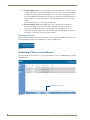
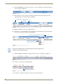
Scheduling IR Device Control Events ...................................................................... 58
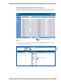
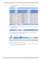
Scheduling Output Device Control Events.............................................................. 61
Scheduling Inputs ................................................................................................... 64
Preset Scheduling ................................................................................................... 67
Scheduling Events - Frequency Options ........................................................................ 68
Configuring the UDM-RC02 Remote Control for Scheduling .................................. 68
Configuration - Protocols Page .........................................................................71
Overview ................................................................................................................ 71
Creating a Serial Protocol ....................................................................................... 72
Updating the UDM Receiver With the Serial Protocol ............................................ 73
Creating and Learning an IR Protocol ..................................................................... 74
IR Learning with a Device’s Remote Control ................................................................. 74
Updating the UDM Receiver With the IR Protocol .................................................. 75
Testing Serial Control Commands........................................................................... 76
Examples of Serial Controls........................................................................................... 77
Deleting Protocols .................................................................................................. 77
Deleting All Protocols (Serial and IR) ...................................................................... 77
Cascading Hubs ................................................................................................79
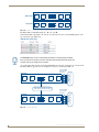
Distributing Video - Using Cascade Kits ................................................................. 79
Using Solecis Distribution Amplifiers to Distribute Video ............................................. 80
Distributing Video - Cascading One UDM-1604C Hub .................................................. 82
Distributing Video - Cascading Two UDM-1604C Hubs................................................. 83
CASCADE IN/OUT Connectors ............................................................................... 84
Cascaded Hub Connection Diagrams ............................................................................ 84
iv
UDM-1604C 4x16 Multi-Format Distribution Hub
Table of Contents
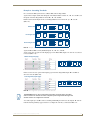
Configuring the Master Hub ................................................................................... 86
Configuring Cascaded Video .................................................................................. 87
Cascading Audio ..................................................................................................... 88
Configuring Cascaded Audio .................................................................................. 89
Example 1 - Cascading One Hub ................................................................................... 89
Example 2 - Cascading Two Hubs ................................................................................. 91
Advanced Administration .................................................................................93
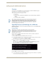
Overview ................................................................................................................ 93
Upgrading Firmware and Web Pages On a UDM Hub............................................ 93
Firmware Update .......................................................................................................... 93
Web Interface Update................................................................................................... 94
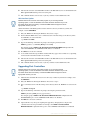
Upgrading Port Controllers .................................................................................... 94
Copying the Hub Configuration File ....................................................................... 95
Restoring the UDM-1604C Configuration file ............................................................... 96
Loading the Hub Configuration File On the UDM-1604C.............................................. 96
Copying Protocols Between UDM Receivers .......................................................... 96
Retrieving IR Files From the UDM Ports........................................................................ 97
Backing up the Hub Configuration File ......................................................................... 97
Restoring the Hub Configuration File............................................................................ 98
Upgrading Input Controllers ................................................................................... 98
Backend Commands ............................................................................................... 99
Changing the Login Password ...................................................................................... 99
Obtaining the Hub’s IP Address Via the Command Line ............................................... 99
Checking Port Details.................................................................................................... 99
Multi Format Inputs....................................................................................................... 99
User Outputs............................................................................................................... 100
Copying IR/Serial Tables ............................................................................................. 100
Endeleo UDM Receiver commands ....................................................................... 101
Viewing Video Compensation Settings ....................................................................... 101
Resetting Video Compensation Settings..................................................................... 102
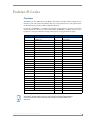
Endeleo IR Codes ...........................................................................................103
Overview .............................................................................................................. 103
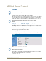
UDM Hub Control Protocol ............................................................................105
Overview .............................................................................................................. 105
UDP (Ethernet) vs SLIP (RS-232) Communication .................................................. 105
Command Format ................................................................................................. 106
Command and Reply Example - Port Connection ................................................. 106
Command and Reply Example - Authentication (Login) ........................................ 107
UDM-1604C 4x16 Multi-Format Distribution Hub
v
Table of Contents
UDP Over Network (10BaseT) Encapsulation........................................................ 107
UDM Over Serial Port (SLIP) Encapsulation........................................................... 107
SLIP Serial Communication Example ..................................................................... 108
Handshaking ......................................................................................................... 109
Command Set ....................................................................................................... 109
Authentication ...................................................................................................... 109
Authenticate (Login) .................................................................................................... 109
Logout......................................................................................................................... 109
Command Summary ............................................................................................. 110
Basic Commands ................................................................................................... 110
Input Numbering ......................................................................................................... 110
Port Numbering .......................................................................................................... 110
Connect Input to Port.................................................................................................. 110
Disconnect Port ........................................................................................................... 111
Input Cascade Selection .............................................................................................. 111
Lock Port ..................................................................................................................... 111
Unlock Port.................................................................................................................. 112
Query Port................................................................................................................... 112
Get Port or Input Name .............................................................................................. 112
Get Receiver Info......................................................................................................... 112
Send Remote Command.............................................................................................. 113
Set Remote Device Protocol ......................................................................................... 113
Send IR Command To Connected Device .................................................................... 114
Send Non-specific Serial Command.............................................................................. 114
Set Serial Parameters ................................................................................................... 114
Get Remote Serial Buffer ............................................................................................ 115
Set Hub Identification ................................................................................................. 115
Get Hub or Port Identification and System Information .............................................. 115
Reset Controller .......................................................................................................... 116
Set Protocol................................................................................................................. 116
Set Port Range ............................................................................................................ 116
Status Values ........................................................................................................ 116
Ascii / Hex Conversion ....................................................................................117
Overview .............................................................................................................. 117
vi
UDM-1604C 4x16 Multi-Format Distribution Hub
Important Safety Markings
Important Safety Markings
Markings Used In This Manual
The following symbols are used on the UDM hardware and throughout this Installation Guide to advise
you of important instructions. All maintenance must be carried out by an AMX trained and qualified
installer.
Voltage
This symbol () warns the presence of a voltage of sufficient magnitude to cause a severe or fatal electric
shock. Follow the appropriate instructions carefully to avoid the risk of injury.
FIG. 1 Voltage symbol
There are NO user serviceable parts within the UDM Hub.
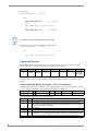
Rating Label
The rating label, containing important safety information, is found on the underside of the UDM Hub.
Symbols used on this label are explained below;
The UDM Hub is powered from a suitable 24 VDC supply.
FCC (Federal Communications Commission) Standards;
TESTED TO COMPLY
WITH FCC STANDARDS
FOR HOME OR OFFICE USE
This device complies with part 15 of the FCC rules.
Operation is subject to the following two conditions:
(1) This device may not cause harmful interference.
(2) This device must accept any interference received
including interference that may cause undesirable operation.
Conforms to particular European Directives.
FIG. 2 Rating Label
UDM-1604C 4x16 Multi-Format Distribution Hub
1
Important Safety Markings
Important Instructions
This symbol, used within this manual, indicates an important instruction for the
correct and safe installation, operation or maintenance of your UDM Hub.
Failure to comply with such instruction may result in injury to person or damage to the
UDM hardware.
Compliance
FCC and IEC
Compliance with FCC and IEC standards are found within the rating label; see above.
Date of Manufacture
For US customers, the date of manufacture is also found underneath the UDM Hub.
UDM-1604C Date of Manufacture Sticker
Model Number
Model number and designation, comprised of up to seven characters.
Vendor ID
One- or two-character ID code.
Date Code
Three-digit date code, comprised of week of year (1-52) and last digit of year.
Consecutive number
Starting at “0001” and continuing to “9999”.
Environmental Conditions
The criteria on this page must be observed for the installation of the UDM-1604C.
Temperature
DO NOT install or operate the UDM Hub in an area where the ambient temperature exceeds 35ºC (95ºF)
or falls below 5ºC (35ºF).
Ventilation
DO NOT obstruct the rear or side ventilation grilles during operation as this will restrict the airflow and
may cause the main board to overheat.
The UDM Hub is fitted with two cooling fans. These draw cool air through the right side ventilation
grille and expel warm air through the grilles on the left side ventilation grilles.
Humidity
DO NOT install or operate the UDM Hub in an area in which the ambient relative humidity exceeds
85% or an area that is prone to condensation.
Water / Liquids
DO NOT install or operate the UDM Hub near water or in a location which may be prone to water
seepage, dripping or splashing.
DO NOT place objects containing liquids on the appliance.
The hub is not waterproof.
External use
DO NOT operate the UDM Hub externally.
2
UDM-1604C 4x16 Multi-Format Distribution Hub
UDM-1604C Multi-Format Distribution Hub
UDM-1604C Multi-Format Distribution Hub
Overview
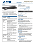
The UDM-1604C 4x16 Multi-format Distribution Hub (FG-UDM-1604C) delivers any video source,
including Component, RGB, VGA and S-Video to a virtually unlimited number of display devices
(FIG. 3).
FIG. 3 UDM-1604C
The UDM-1604C supports four high-resolution input ports and 16 UDM output ports, and supports
multiple methods of delivering sync information between the UDM Hub and the display device,
including common mode.
The UDM-1604C delivers media over easily-installed, dedicated Cat5/5e/6, which de-couples
distribution of the media from the corporate backbone. Users can quickly switch and transmit any video
source to the display device, power on/off display devices, and permission user control to select and play
video sources and media servers on demand.
The UDM-1604C offers four high-resolution input ports on the back of each unit. Additional Composite
video inputs (RJ-45 located on the front) enable the connection of four interconnects from a TVM-1600
Managed TV Distribution Hub or four Composite video sources using approved Video over UTP
extenders.
In total, the UDM-1604C system can distribute any combination of the following: four RGBHV sources,
four Component video sources, four S-Video sources or 12 Composite video sources.
Source inputs to the UDM are industry standard VGA, Composite, Component or S-Video feed, and
output is presented as an RJ45 port for connection to Cat5, 5e or 6 twisted-pair Ethernet cable.
Video inputs are connected via the HD15 Input connector on the rear of the UDM. Adapters are used to
bring the different types of video source into the UDM. See the Audio & Video Formats/Resolutions/
Distance section on page 14 for tested and confirmed distances.
Each UDM has an Ethernet network port to provide connectivity to a central management system, or can
be controlled by the onboard configuration pages. A Serial connection is also provided for CLI
administration and diagnostic purposes.
Features
4 multi-format inputs (plus 4 CVBS inputs) x 16 outputs
Supports multiple methods of delivering sync, including Common Mode Sync delivery
Digital audio support
Central device control
Compatible with TVM-1600
1U rack-mounting
Multiple Hubs can be cascaded to support higher number of outputs
UDM-1604C 4x16 Multi-Format Distribution Hub
3
UDM-1604C Multi-Format Distribution Hub
Compatibility
The UDM-1604C is compatible for use with UDM-RX01 (FG-UDM-RX01) and UDM-RX02
(FG-UDM-RX02) Receivers.
Common Mode Sync delivery is supported only on the UDM-RX02.
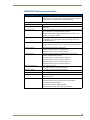
Product Specifications
UDM-1604C Specifications
Power Requirements:
• 90-264V AC, 50/60Hz
• Max power consumption: 130W
Front Panel Components
IR Sensor:
Infrared receive port (IRRX) for learning IR remote control functions from IR controlled devices.
Outputs:
16 RJ-45 ports for connection to Endeleo TVM hubs (via Cat5, Cat5e or Cat6).
A/V Inputs:
4 RJ-45 ports for connection from Endeleo TVM hubs (via Cat5, Cat5e or Cat6).
Rear Panel Components
Network Port:
RJ-12 10 BaseT network port is provides network connectivity.
Serial Port:
RJ-12 port allows an administrator to control various functions from a command
line prompt.
IRTX Ports:
2 Infrared Transmit (IRTX) ports allow the UDM Hub to control IR devices via IR
emitters attached to the UDM. The IR cable is attached to the IR panel of the controlled device to receive IR commands issued through the software or remote
control.
Input Connectors (A-D):
4 sets of Input connections for up to 4 A/V inputs with the following connectors:
• Video
• Audio Left
• Audio Right
• SPDIF
Cascade IN/OUT Ports:
These ports allow UDM Hubs to be cascaded together.
• Cascade In Port (from another UDM Hub)
• Cascade Out Port (to another UDM Hub)
IEC Power Connector:
Universal switch-mode power supply.
• As a Class 1 appliance the Hub should be connected to a mains supply with a
protective earthing connection.
• The Power On/Off switch is located beside the IEC power connector.
Note: The rating label found to the bottom left of the hub, beneath the IEC connector, contains important information applicable to the Hub’s installation environment.
Network Interface:
10baseT
Serial Interface:
9600, 8, N, 1
Max Video Input:
• 4 x RGBHV (or)
• 4 x S-Video (or)
• 12 x CVBS (plus)
• 4 x Endeleo TVM-1600 or CVBS
4
UDM-1604C 4x16 Multi-Format Distribution Hub
UDM-1604C Multi-Format Distribution Hub
UDM-1604C Specifications
Operating Environment:
• 35°F - 95°F (5°C - 35°C)
Dimensions (HWD):
1 3/4" x 19" x 12 1/2" (45 mm x 440 mm x 320 mm)
Weight:
8.8 lb. (4 Kg)
Certifications:
• CE/UL/FCC part 15 Class A
Included Accessories:
• IEC power cord
• Max. relative humidity - 85% (non-condensing)
• 19" mounting brackets
• RS-232 DB-9/RJ-12 connection cable
Note: No A/V interface cables supplied
Other AMX Equipment:
• HD15 to S-Video Cable (FG-UDM-SVID01)
• HD15 to 3x RCA Breakout Cable (FG-HD15RCA3)
• RS232 DB9/RJ12 Connection Cable (FG-RS01)
• UDM-RX02 Multi-Format Receiver (FG-UDM-RX02)
• UDM-RC10 IR Engineering Remote Control (FG-UDM-RC10)
• IR01 IR Emitter Module (FG-IR01)
• IR03 External IR Receiver Module (FG-IR03)
• Solecis Distribution Amplifiers (see the Solecis Distribution Amplifiers table on
page 79 for listing od compatible DAs)
UDM-1604C 4x16 Multi-Format Distribution Hub
5
UDM-1604C Multi-Format Distribution Hub
6
UDM-1604C 4x16 Multi-Format Distribution Hub
Installation
Installation
Overview
The UDM-1604C occupies a single rack space in a standard 19" equipment rack. Rack mounting
brackets and screws are located in the accessories box supplied with the UDM-1604C.
Exercise extreme care when lifting or moving the hub within the rack to avoid injury. It
is recommended that you seek the assistance of another person when rack mounting
the UDM-1604C.
Rack mounting brackets and screws are located in the accessories box supplied with the UDM-1604C.
1. Attach the rack mounting brackets to each side of the UDM-1604C using four M4 screws for each
bracket (FIG. 4).
FIG. 4 Attach the mounting brackets to each side of the Hub
To prevent injury the Hub must be securely attached to the rack in accordance with
the installation instructions.
ALWAYS use the special rack mount brackets supplied and high quality fixing screws
to ensure the hub is installed in the rack correctly.
2. Place the UDM-1604C in the Rack and hold steady.
3. Two fixing holes are supplied on each side of the UDM-1604C. Screw the hub into the rack using
the fixing holes (FIG. 5).
FIG. 5 Screw the hub into the rack using the fixing holes
DO NOT stand other units directly on top of the hub when it is rack mounted, as this
will place excessive strain on the mounting brackets.
Ventilation
ALWAYS ensure that the rack enclosure is adequately ventilated.
Sufficient airflow must be achieved (by convection or forced-air cooling) to satisfy the ventilation
requirements of all the items of equipment installed within the rack.
UDM-1604C 4x16 Multi-Format Distribution Hub
7
Installation
8
UDM-1604C 4x16 Multi-Format Distribution Hub
Wiring and Connections
Wiring and Connections
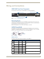
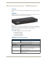
UDM-1604C Front Panel Components
The components on the front panel of the UDM-1604C are described below (FIG. 6).
4 RJ45 Output Ports for
connection to TVM Hubs
IR Learning Sensor
16 RJ45 Output Ports for connection
to UDM-RX01/RX02 Receivers
FIG. 6 UDM-1604C - Front Panel Components
IR Learning Sensor
An IR receive port is found at the front of the UDM Hub to the right hand side. This is used to learn
device IR remote control functions from devices such as DVD players, VCRs etc. Common functions
learned include Power on, Power off, Play, Pause, Stop, etc.
Refer to the Configuration - Protocols Page section on page 71 for details.
OUTPUT Ports (RJ-45)
The 16 RJ-45 ports on the front panel of the UDM (labelled “OUTPUTS”) provide connectivity to
UDM-RX01 or UDM-RX02 Multi-Format Receivers. This is a standard RJ-45 connector, and UDM
Receivers can be connected via either Cat5, Cat5e or Cat6 cabling (FIG. 7).
FIG. 7 RJ-45 Pinouts
UDM Port Pinouts
The following table describes the pinout configuration of the UDM port:
UDM Port Pinouts
Pair
Color
RJ45 Pin
Polarity
White / Blue
5
-
Blue
4
+
White / Orange
1
+
Orange
2
-
White / Green
3
+
Green
6
-
White / Brown
7
+
Brown
8
-, Gnd
1
2
3
4
Endeleo Function
Green
UDM-1604C 4x16 Multi-Format Distribution Hub
Red
Blue
Bi-Directional Control, Digital Audio, Phantom Power
9
Wiring and Connections
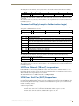
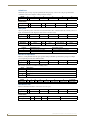
UDM Port Transmission Details
The following table provides transmission details for the UDM port:
Transmission on UDM Port
Pair
Pin
UDM (CVBS)
UDM (SVideo)
UDM (YPbPr)
UDM (RGB)
Pair
Pin
CVBS +
Luma +
Y+
Red +
2
1
CVBS -
Luma -
Y-
Red -
2
2
Chroma +
Pr+
Blue+
3
3
Pb+
Green +
1
4
Pb-
Green -
1
5
Chroma -
Pr-
Blue -
3
6
Power, Data, Audio
Power, Data, Audio
Power, Data, Audio
Power, Data, Audio
4
7
Power, Data, Audio
Power, Data, Audio
Power, Data, Audio
Power, Data, Audio
An incorrectly terminated cable will result in the following scenarios:
Incorrectly terminated cable results
Pair
Composite
Video
SVideo
Component
Video
RGBHV
Video
User Port
LINK LED
2
No Video 1
No Luma
No Y
No RED
LIT
3
No Video 3
No Chroma
No Pr
No BLUE
LIT
1
No Video 2
NONE
No Pb NONE
No GREEN
NONE
LIT NONE
4
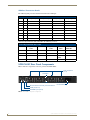
UDM-1604C Rear Panel Components
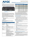
FIG. 8 shows the components on the rear panel of the UDM-1604C:
Input connections
(A - D)
Cascade In
Cascade Out
IRTX connections for locally connected devices
Serial port (RJ-12)
ETHERNET port (RJ-45)
IEC Power cable
connector/switch
FIG. 8 UDM-1604C - rear panel components
10
UDM-1604C 4x16 Multi-Format Distribution Hub
Wiring and Connections
Network Port (RJ45)
The RJ45 Network port on the rear panel of the UDM-1604C provides 10 BaseT network connectivity.
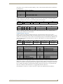
Pinout Configuration
The following table lists the pinouts, signals, and pairing for the Network port.
RJ45 Network Port Pinouts and Signals
Pin
Signals
Connections
1
TX +
1 --------- 1
2
TX -
2 --------- 2
Pairing
Color
1 --------- 2 Orange-White
Orange
3
RX +
3 --------- 3
4
no connection
4 --------- 4
3 --------- 6
Green-White
Blue
5
no connection
5 --------- 5
Blue-White
6
RX -
6 --------- 6
Green
7
no connection
7 --------- 7
Brown-White
8
no connection
8 --------- 8
Brown
FIG. 9 diagrams the pinouts and signals for the Network RJ45 connector and cable.
FIG. 9 RJ45 wiring diagram
Consult the Network Administrator for correct cabling from the UDM-1604C onto the
network. For remote connectivity, the Firewall may have to be configured to open port
2008 for remote connectivity over UDP
Default IP Address
The default IP address of the UDM-1604C is 192.168.0.96.
Once the UDM-1604C is switched on, use the Setup option in the UDM WebConsole to configure the
Hub’s correct IP address (see the Configuration - Setup Page section on page 45).
The IP address may also be configured via the serial port (refer to the Backend Commands section on
page 99).
UDM-1604C 4x16 Multi-Format Distribution Hub
11
Wiring and Connections
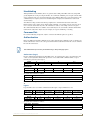
Serial Port
The Serial port on the rear panel (labelled “10101”) is available for diagnostic and troubleshooting
purposes.
Connecting the Serial port on the UDM-0102 is not an essential step in the
installation process.
The Serial port on the UDM-1604is an RJ12 connector, and requires a DB9-to-RJ12 adapter cable
(FG-RS01) to connect to a PC for Terminal control.
Serial Port - Default Communication Settings
Use hyper terminal with default serial settings to communicate with the UDM-1604C (and UDMRX01):
Default Serial Settings
Baud Rate:
9600
Data Bits:
8
Parity:
None
Stop Bits:
1
Flow Control:
None
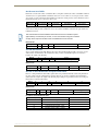
DB9-to-RJ12 Adapter Cable Pinouts
The following table provides the pinout configuration for the DB9-to-RJ12 adapter cable:
DB9-to-RJ12 Adapter Cable Pinouts
DB9 connector
12
Function
Abbreviation
RJ12 connector
Pin 1
Not used
NC
Pin 2
Transmit Data
TD or TX or TXD
Pin 3
Receive Data
RD or RX or RXD Pin 3
Pin 4
Data Set Ready
DSR
Pin 1
Pin 5
Signal Ground
GND
Pin 4, 5
Pin 6
Data Terminal Ready DTR
Pin 7
Not Used
NC
Pin 8
Not Used
NC
Pin 9
Not Used
NC
Pin 2
Pin 6
UDM-1604C 4x16 Multi-Format Distribution Hub
Wiring and Connections
IRTX (IR Transmit) Ports
Two 3.5mm stereo IRTX connections issue IR commands from the UDM Hub to the controlled
device(s):
TX1 – Transmits IR commands to Device 1
TX2 – Transmits IR commands to Device 2
A maximum of two IR devices (such as DVD players or VCRs) can be connected to the UDM via the
IRTX ports on the rear panel (FIG. 10), and controlled via the WebConsole or remote control.
IRTX1 IR Transmitter port (3.5mm stereo output)
IRTX2 IR Transmitter port (3.5mm stereo output)
IRRX IR Receiver port (3.5mm stereo input)
FIG. 10 IR Transmit/Receive Ports
IR devices controlled via the IRTX ports are typically installed within the same
equipment rack as the UDM.
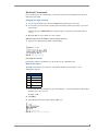
Connecting an IR Device to an IRTX Port
To issue IR commands to the display device such as power on or power off, an IR01 Endeleo IR Emitter
Module (FG-IR01) is needed:
FIG. 11 IR01 Endeleo IR Emitter Module
Ensure the position of the device corresponds to the position assigned in the Devices
option of the UDM-0102’s WebConsole.
1. Connect the IR Emitter Module cable to the appropriate IRTX port on the UDM-0102.
2. Run the other end of the cable to the display device, and attach the IR Emitter over the device’s IR
sensor by removing the cover on the reverse side of the IR Emitter.
3. The UDM-0102 is now capable of issuing IR commands to the display device.
IR commands for each device on the system have to be learned by the UDM-0102 in order to function
properly. Refer to the Creating and Learning an IR Protocol section on page 74 on how to learn a
device’s IR commands.
UDM-1604C 4x16 Multi-Format Distribution Hub
13
Wiring and Connections
A/V Source Input Connectors
There are four sets of input connectors to the rear panel of the UDM-1604C, labelled A, B, C and D
(FIG. 12).
Digital Audio Input (SPDIF)
RCA Audio Inputs (L/R)
Video Input (female HD15)
FIG. 12 A/V Source Input connectors (A and B shown)
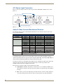
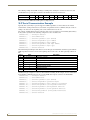
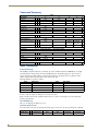
Audio & Video Formats/Resolutions/Distance
The following table provides recommended maximum distances for cable runs, based on video class
type at various resolutions:
Audio & Video Formats/Resolutions/Distance
Class
Format
Name
UDM-RX01
UDM-RX02
Composite
720x480
NTSC
300 m / 1000’
300 m / 1000’
720x576
PAL
300 m / 1000’
300 m / 1000’
720x480
480p
300 m / 1000’
300 m / 1000’
720x576
576p
300 m / 1000’
300 m / 1000’
1280x720
720p
200 m / 650’
300 m / 1000’
1920x1080
1080i
150 m / 500’
300 m / 1000’
1920x1080
1080p
120 m / 400’
300 m / 1000’
640x480
VGA
200 m / 650’
300 m / 1000’ *
Component
VGA
800x600
SVGA
200 m / 650’
300 m / 1000’ *
1024x768
XGA
200 m / 650’
300 m / 1000’ *
1280x1024
SXGA
150 m / 500’
300 m / 1000’ *
1600x1200
UXGA
120 m / 400’
300 m / 1000’ *
* When using VGA modes with audio enabled, the maximum cable distance is
approximately 200 m / 650’ (UDM-RX02).
It is important to note that the maximum distances indicated above are not absolute, but are
recommended distances that have been tested to deliver video at the specified resolutions, without
significant signal degradation. In particular, lower resolutions (640 x 480, 720 x 480 and 800 x 600) can
often be delivered significantly further than what is indicated in the table.
Several factors affect the overall quality of the displayed video, including the quality of the twisted pair
cable and connectors used, the nature of the video image itself, as well as the particulars of the
installation and how the video is displayed and viewed.
Two major factors affect the quality of signal transmission include:
Cable Distance: Naturally, long distances cable runs (in excess of 300 meters/1000 feet) are
always subject to resistance and capacitance losses which can negatively impact the quality of
the image.
Skew: "Skew" represents the slight delay that results from the variation in wiring lengths for
each of the twisted pairs. The effects of skew on A/V signals increases with cable length.
14
UDM-1604C 4x16 Multi-Format Distribution Hub
Wiring and Connections
Excessive skew can adversely affect video image quality, especially at long cable lengths and
high signal resolutions.
UDM Hubs allow you to compensate brightness, sharpness and skew delay via options in the Status page
of the UDM’s built-in WebConsole (see the Video Compensation section on page 29).
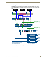
VIDEO IN Connectors (HD15)
FIG. 13 provides the pin layout for the VIDEO IN HD15 Connectors:
HD15 Pinouts
5
4
10
15
3
9
14
2
8
13
1
7
12
6
11
Input Pin
1
2
3
4
5
6
7
8
9
10
11
12
13
14
15
Component
VGA
Pr
Red
Y
Green
Pb
Blue
n/c
n/c
n/c
Ground
Pr - Ground
Red - Ground
Green - Ground Y - Ground
Pb - Ground
Blue - Ground
n/c
n/c
n/c
Ground
n/c
n/c
n/c
n/c
n/c
Horz. Synch
n/c
Vert. Synch
n/c
n/c
S-Video
Luminance
n/c
Chrominance
n/c
n/c
Luminance - Ground
n/c
Chrominance - Ground
n/c
n/c
n/c
n/c
n/c
n/c
n/c
Composite
CVBS1
CVBS2
CVBS3
n/c
n/c
CVBS1 - Ground
CVBS2 - Ground
CVBS3 - Ground
n/c
n/c
n/c
n/c
n/c
n/c
n/c
FIG. 13 VIDEO IN HD15 Connector
Connecting a VGA Video Input
1. Connect one end of a VGA cable to the source device’s VGA output port.
2. Attach the other end of the cable to the appropriate VIDEO IN connection (A or B) on the UDM.
For example, connect to the Video In connection on Input A of the Hub.
3. Connect any audio to the analog (RCA) audio connectors or digital (SPDIF) connector.
Ensure the UDM Hub port the RX01/RX02 is attached to is configured correctly within
the Hub’s configuration software. Also ensure the correct Audio Type (Analog L/R, S/
PDIF, or None) is selected for the relevant input. Refer to the Configuration - Inputs
Page section on page 49 for details.
Connecting a Composite Video Input
1. Connect the UDM-HD15RCA3 Breakout Cable (FG-HD15RCA3, not included) to the source
device’s Composite output ports:
A1 = red RCA
A2 = green RCA
A3 = blue RCA
2. Attach the other end of the cable to the appropriate VIDEO IN connection (A or B) on the UDM.
3. Connect any audio to the analog (RCA) audio connectors or digital (SPDIF) connector.
Connecting a Component Video Input
1. Connect the UDM-HD15RCA3 Breakout Cable (FG-HD15RCA3, not included) to the video source
device’s Component video output connectors (Red, Green and Blue).
2. Attach the other end of the cable to the appropriate VIDEO IN connection (A or B) on the UDM.
3. Connect any audio to the analog (RCA) audio connectors or digital (SPDIF) connector.
UDM-1604C 4x16 Multi-Format Distribution Hub
15
Wiring and Connections
Connecting an S-Video Input
1. Connect the UDM-SVID01 HD15 to SVideo cable (FG-UDM-SVID01, not included) to the video
source’s S-Video connection.
2. Attach the other end of the cable to the appropriate VIDEO IN connection (A or B) on the UDM.
3. Connect any audio to the analog (RCA) audio connectors or digital (SPDIF) connector.
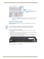
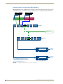
Cascade IN/OUT Ports
The Cascade IN and Cascade Out ports allow UDM Hubs to be chained together to increase the number
of inputs which can be delivered to the end points (FIG. 14). This is known as "cascading" the hubs.
FIG. 14 Cascade IN/OUT Ports
The Cascade In and Cascade Out ports are used to cascade two UDM hubs.
A UDM-EXP-01 cascade cable (optional) is required to connect the UDM hubs together.
Refer to the Cascading Hubs section on page 79 for details on configuring cascaded Hubs.
IEC Power Connector
The UDM-1604C uses a universal switch-mode power supply, which operates from 90-264V AC,
50/60Hz, with a power consumption of 130W fully loaded.
The rating label found to the bottom left of the hub, beneath the IEC connector, contains
important information applicable to the Hub's installation environment.
The Power On/Off switch is located beside the IEC power connector.
As a Class 1 appliance the UDM-1604C should be connected to a mains supply with
a protective earthing connection.
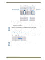
Powering the UDM-1604C Hub On
1. Ensure a standard PC mains lead has been connected to the 3-pin power connection, and then
connected to a mains power source.
2. Flip the power switch down to its On (|) position.
Powering the UDM-1604C Hub Off
Where a mains plug (or appliance coupler) is used in the event of a fault, the hub can
be disconnected from the mains by removing the lead from the IEC inlet or from the
mains socket.
It is important that the hub is installed in such a way that this method remains readily
operable.
The user should have easy access to either the IEC inlet or the mains socket in the
event of a fault.
To turn the UDM-1604C off, flip the Power switch to it’s Off (0) position.
16
UDM-1604C 4x16 Multi-Format Distribution Hub
Wiring and Connections - UDM Receivers
Wiring and Connections - UDM Receivers
Overview
UDM Receivers include the UDM-RX01 and UDM-RX02. Each Receiver is described in the following
sections.
UDM-RX01
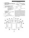
Installed at the display device, the UDM-RX01 (FG-UDM-RX01) converts the signal received from a
UDM Multi-Format Distribution Hub to standard A/V signals (FIG. 15).
FIG. 15 UDM-RX01
With intelligent receiver technology, each UDM-RX01 is powered directly from the UDM Multi-Format
Distribution Hub. As the hub is switched from one video/audio source to another, the receiver detects a
change in signal and automatically switches the output device to its new video format.
UDM Hub Compatibility
The UDM-RX01 is compatible for use with the following UDM Hubs:
UDM-0102 (FG-UDM-0102)
UDM-0404 (FG-UDM-0404)
UDM-1604C (FG-UDM-1604C)
UDM-1604 (FG-UDM-1604)
UDM-RX01 Product Specifications
UDM-RX01 Specifications
Power Requirements:
24VDC @ .75A
Note: The UDM-RX01 is remotely powered by the UDM Multi-Format Distribution Hub (see Powering on the UDM-RX02 ).
Rear Panel Connectors:
Power Socket:
2.1mm barrel-style DC power socket (female)
UDM Hub (RJ45) Port:
Provides audio/video transport as well as control via Cat5, Cat5e or Cat6 to
an UDM Hub.
Serial (RJ12) port:
Enables an administrator to control the various functions to the UDM-RX01
from a command line prompt and terminal connection.
• Requires a DB9-to-RJ12 adapter cable (FG-RS01) to connect to a PC.
• 9600, 8 bit, No Parity, 1 Stop Bit
IR Rx Port:
UDM-1604C 4x16 Multi-Format Distribution Hub
3.5mm stereo input port, for connection of an IR receiver to allow setup of
the UDM-RX01, local compensation controls, and remote control of centrally located IR devices.
17
Wiring and Connections - UDM Receivers
UDM-RX01 Specifications (Cont.)
IR Tx Port:
3.5mm stereo IR Transmitter output port allows one IR-controlled device
(such as a DVD or VCR player) to be controlled via optional wired IR emitter.
Audio Connectors:
• Black RCA female connector - Digital audio
• White RCA female connector - Analog audio Left
• Red RCA female connector - Analog audio Right
Video Connectors:
• Yellow RCA female connector - CVBS (supports composite video)
• S-Video - S-video female connector
• VGA - HD15 female connector (supports VGA video)
• Green RCA female connector - Component output: Y
• Blue RCA female connector - Component output: Pb
• Red RCA female connector - Component output: Pr
Operating Environment:
• 35°F - 95°F (5°C - 35°C)
• Max. relative humidity - 85% (non-condensing)
Dimensions (HWD):
1" x 8 15/16” x 3 3/8” (25 mm x 227 mm x 85 mm)
Weight:
1.45 lb. (658 g)
Certifications:
• CE
Other AMX Equipment:
• RS232 DB9/RJ12 Connection Cable (FG-RS01)
• FCC part 15 Class A
• UDM-RC02 Multi-Format IR Remote Control (FG-UDM-RC02)
• IR01 IR Emitter Module (FG-IR01)
• IR03 External IR Receiver Module (FG-IR03)
• UDM-PS 24VDC, 750mA Power Supply (FG-UDM-PS)
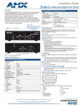
UDM-RX02
With all the same features of the UDM-RX01, the UDM-RX02 adds support for “Common” mode sync,
as well as remote power for long cable distance runs. (FIG. 16).
FIG. 16 UDM-RX02
UDM-RX02 - UDM Hub Compatibility
The UDM-RX02 is compatible for use with the following UDM Hubs:
UDM-0102 (FG-UDM-0102) - This hub supports Common Synch Mode.
UDM-0404 (FG-UDM-0404) - This hub supports Common Synch Mode.
UDM-1604C (FG-UDM-1604C) - This hub supports Common Synch Mode.
UDM-1604 (FG-UDM-1604) - This hub does not support Common Synch Mode. In this case,
the UDM-RX02 will function, but without Common Synch Mode.
18
UDM-1604C 4x16 Multi-Format Distribution Hub
Wiring and Connections - UDM Receivers
UDM-RX02 Product Specifications
UDM-RX02 Specifications
Power Requirements:
24VDC @ .75A
Note: In most cases the UDM-RX02 is remotely powered by the UDM MultiFormat Distribution Hub (see Powering on the UDM-RX02 ).
Rear Panel Connectors:
Power Socket:
2.1mm barrel-style DC power socket (female)
UDM Hub (RJ45) Port:
Provides audio/video transport as well as control via Cat5, Cat5e or Cat6 to
an UDM Hub.
Serial (RJ12) port:
Enables an administrator to control the various functions to the UDM-RX02
from a command line prompt and terminal connection.
• Requires a DB9-to-RJ12 adapter cable (FG-RS01) to connect to a PC.
• 9600, 8 bit, No Parity, 1 Stop Bit
IR Rx Port:
3.5mm stereo input port, for connection of an IR receiver to allow setup of
the UDM-RX02, local compensation controls, and remote control of centrally located IR devices.
IR Tx Port:
3.5mm stereo IR Transmitter output port allows one IR-controlled device
(such as a DVD or VCR player) to be controlled via optional wired IR emitter.
Audio Connectors:
• Black RCA female connector - Digital audio
• White RCA female connector - Analog audio Left
• Red RCA female connector - Analog audio Right
Video Connectors:
• Yellow RCA female connector - CVBS (supports composite video)
• S-Video - S-video female connector
• VGA - HD15 female connector (supports VGA video)
• Green RCA female connector - Component output: Y
• Blue RCA female connector - Component output: Pb
• Red RCA female connector - Component output: Pr
Operating Environment:
• 35°F - 95°F (5°C - 35°C)
• Max. relative humidity - 85% (non-condensing)
Dimensions (HWD):
1" x 8 15/16” x 3 3/8” (25 mm x 227 mm x 85 mm)
Weight:
1.45 lb. (658 g)
Certifications:
• CE
Other AMX Equipment:
• RS232 DB9/RJ12 Connection Cable (FG-RS01)
• FCC part 15 Class A
• UDM-RC02 Multi-Format IR Remote Control (FG-UDM-RC02)
• IR01 IR Emitter Module (FG-IR01)
• IR03 External IR Receiver Module (FG-IR03)
• UDM-PS 24VDC, 750mA Power Supply (FG-UDM-PS)
UDM-1604C 4x16 Multi-Format Distribution Hub
19
Wiring and Connections - UDM Receivers
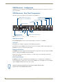
UDM Receivers - Configuration
UDM Receivers are configured via the UDM Hub’s WebConsole. Refer to the Configuration section on
page 25 for details.
UDM Receivers - Rear Panel Components
All of the connectors and ports are located on the rear panel (FIG. 17):
Composite (Pr) port
Composite (Pb) port
Composite (Y) port
VGA (HD15) port
S-Video port
CVBS port
UDM HUB port (RJ45) - from an
“OUTPUT” port on the UDM-0102
Serial port (RJ12)
IR Rx port
IR Tx port
Power connector
(UDM-RX02 only)
RCA audio
(left/right)
SPDIF female Digital Audio port
FIG. 17 UDM Receivers - rear panel components (UDM-RX02 shown)
UDM Hub Port (RJ45)
The UDM-RX01/RX02 connects to the network through a connection to a UDM Hub.
Serial Port
The Serial port is available for diagnostic and troubleshooting purposes.
The Serial port on the UDM Receiver is an RJ12 connector, and requires a DB9-to-RJ12 adapter cable
(FG-RS01) to connect to a PC for Terminal control.
IR Receiver (IR Rx) Port
The IR Rx port is used to enable user control and the remote compensation of the video link to the UDM
Receiver, using the FG-UDM-RC10 and the FG-IR03.
Refer to the Creating and Learning an IR Protocol section on page 74 for information on learning a
device’s IR commands.
IR Transmit (IR Tx) Port
The IR Tx port issues IR commands from the UDM Receiver to a controlled device. One IR device
(such as DVD player or VCR) can be connected to the UDM Receiver via the IR Tx port, and controlled
via the UDM Hub’s WebConsole or via remote control.
IR devices controlled via the IRTX ports are typically installed within the same
equipment rack as the UDM Hub and Receiver.
20
UDM-1604C 4x16 Multi-Format Distribution Hub
Wiring and Connections - UDM Receivers
Connecting an IR Device to the IR Tx Port
1. Connect an IR01 Endeleo IR Emitter Module (FG-IR01) to the IR Tx port on the UDM Receiver.
Ensure the position of the device corresponds to the position assigned in the Devices
option of the UDM- Hub’s WebConsole.
2. Run the other end of the IR Emitter cable to the device’s IR sensor, and attach the IR Emitter to the
device’s sensor by removing the cover on the reverse side of the IR Emitter.
IR commands for each device on the system have to be learned by the UDM Hub in order to function
properly. Refer to the Creating and Learning an IR Protocol section on page 74 for information on
learning a device’s IR commands.
AUDIO Connectors
UDM Receivers provide standard Audio RCA output connectors for S/PDIF for digital audio, and
LEFT/RIGHT for analog audio output (see FIG. 17 on page 20).
VIDEO Connectors
VGA Input at Display Device
1. Attach one end of the Endeleo VGA to VGA cable to the VGA connector on the UDM Receiver.
2. Run the other end to the VGA connector on the display device. Connect firmly.
3. If appropriate connect audio to the audio connectors on the UDM Receiver.
Ensure Input A is configured as a “VGA Input” and named appropriately within the
“Inputs” section of the Hub’s Configuration software. Also ensure the correct Audio
Type (Analog L/R or S/PDIF) is selected for the relevant input.
Composite Input at Display Device
1. Attach the composite cable (normally yellow) to the CVBS connector on the UDM Receiver.
2. Run the other end of the composite cable to the Composite connector (normally yellow) on the
display device. Connect firmly.
3. If appropriate connect audio to the audio connectors on the UDM Receiver.
SVideo Input at Display Device
1. Attach the SVideo cable to the 4-pin S Video connector on the UDM Receiver.
2. Run the other end of the SVideo cable to the SVideo connector on the display device. Connect
firmly.
3. If appropriate connect audio to the audio connectors on the UDM Receiver.
Component Input at Display Device
1. Attach the Component cables (normally green, blue and red) to the Y (green), Pb (blue) and Pr
(red) connectors on the UDM Receiver.
2. Run the other end of the Component cable to the Component connectors (normally green, blue and
red) on the display device. Connect firmly.
3. If appropriate connect audio to the audio connectors on the UDM Receiver.
UDM-1604C 4x16 Multi-Format Distribution Hub
21
Wiring and Connections - UDM Receivers
Audio & Video Formats/Resolutions/Distance
Refer to the Audio & Video Formats/Resolutions/Distance section on page 14.
Video Compensation
Video at the Receive end can be compensated using three main methods;
Using the UDM Hub’s WebConsole.
Using the UDM-RC02 Multi-Format IR Remote Control.
Using a hyper terminal session via the serial connector on the UDM Receiver (especially
effective setup method when using long runs).
Connecting an External IR Receiver Module
If passthrough mode (where a device such as a DVD or VCR can be controlled via a remote control) is
required then an IR03 External IR Receiver Module will be needed to pick up IR controls from the
remote control.
Additionally, if the UDM Receiver is to be compensated via a remote control, then an IR Receiver
Module is also needed.
Connecting the UDM Receiver to the UDM Hub
The RJ45 port on the front panel of the UDM Hub labelled “UDM” supports one UDM Receiver. The
UDM Receiver is then be connected to a display device.
1. Connect a standard Cat5/6 Ethernet cable to the RJ45 port labelled UDM on the front panel of the
UDM Hub.
2. Connect the other end of the Ethernet cable to the RJ45 port labelled UDM Hub on the rear panel of
the UDM Receiver.
Ensure the port the UDM-RX01/RX02 is attached to is configured correctly within the
Status option of the WebConsole (for example, if a UDM Receiver is connected to the
Hub, ensure the port in the Status option is configured likewise.
UDM HUB Port LEDs
2 LEDs are visible at the UDM Hub port (on the UDM-RX01/RX02) when the UDM Hub is switched
on:
Green – Connection to UDM Hub (if Cat 5 removed, LED switches off).
Amber – Power (as well as comms if uploading protocols etc. the Amber LED may flicker).
While connected receivers may be powered through the UDM Hub, using separate
power sources for each receiver is highly recommended, especially with receivers
connected to the 15th and 16th ports.
22
UDM-1604C 4x16 Multi-Format Distribution Hub
Wiring and Connections - UDM Receivers
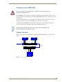
Powering on the UDM-RX02
As a Class 1 appliance, ensure the device is connected to a main socket outlet with a
protective grounding connection.
The UDM-RX02 may be powered by its hub device through a standard CAT5 cable, but it may also be
powered through an optional 24 VDC power supply (FG-UDM-PS) intended to augment power for very
long cable runs.
To connect the UDM Receiver to the optional power supply, insert the barrel connector of the power
supply into the power connector on the UDM Receiver (see FIG. 17 on page 20).
To power down the UDM-RX02, remove the barrel connector of the power supply from the power
connector and then remove the Ethernet cable from the UDM Hub connector.
Disconnecting the optional power supply will not power down the UDM-RX02 if its
Ethernet connection to the UDM Hub is intact.
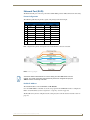
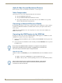
System Overview
FIG. 18 provides a basic system diagram representing a UDM Hub, UDM Receiver, and connected
devices:
DVD
Video Out
Video In
DSS
Audio Out
Video Out
Video In
Audio In
Audio Out
Audio In
UDM Hub
Ethernet
(network
Ethernet
UDM Receiver
Video Out
Video In
Audio Out
Audio In
Display
FIG. 18 UDM System Diagram
UDM-1604C 4x16 Multi-Format Distribution Hub
23
Wiring and Connections - UDM Receivers
24
UDM-1604C 4x16 Multi-Format Distribution Hub
Configuration
Configuration
WebConsole Overview
Each UDM-1604C Hub can be configured for the correct network environment. It is also possible to
configure each Hub for the correct date and time. Configuration options are available via the UDM’s
built-in WebConsole, as described in this section.
The UDM-RX02 Receiver connected to the UDM-1604C is also configured via the 1604’s WebConsole.
This section describes the pages that comprise the UDM-1604C’s WebConsole
interface in the order that they are presented (“Status”, “Setup”, "Inputs", "Devices"
“Schedule” and “Protocols”). However, on initial connection, you’ll probably need to
visit the Setup page first, to specify network configuration and other basic device
setup options for the Hub.
See the Configuration - Setup Page section on page 45 for details.
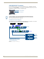
Connecting to the UDM-1604C
Use the included Ethernet Crossover cable for initial setup.
1. The default IP address of the UDM-1604C is 192.168.0.96.
2. Enter the IP address into the address field within a browser window.
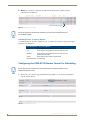
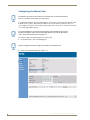
3. To connect to the UDM-1604C, a password is required.
The username should be left blank.
The password is admin (case-sensitive).
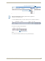
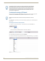
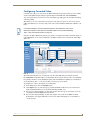
4. On initial connection, the Status page is displayed (FIG. 19) .
Click links to access the six main
areas of the WebConsole
(initial view is Status)
FIG. 19 Status page (Initial View)
UDM-1604C 4x16 Multi-Format Distribution Hub
25
Configuration
After setup you can change TCP/IP address and connect the UDM-1604C to your network equipment
(switch, hub, or serial port).
Use the links in the left-pane of the page to access each of the main Configuration pages, as described in
the following sections.
26
UDM-1604C 4x16 Multi-Format Distribution Hub
Configuration - Status Page
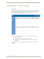
Configuration - Status Page
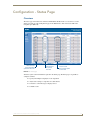
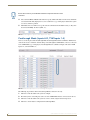
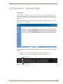
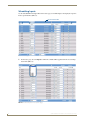
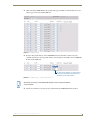
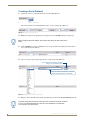
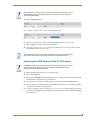
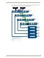
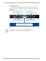
Overview
The Status page is the initial view when the UDM-1604C’s WebConsole is accessed. To access the
Status page from any other Configuration page in the WebConsole, click on the Status link in the
navigation pane (FIG. 20).
Click to access
Port Configuration
options for each Port
Click to select
an Input for
each Port
Click to access
User Control options
for each Port
FIG. 20 Main Status page
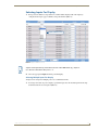
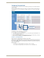
All of the system control is handled via options in the Status page. From this page it is possible to
configure each Port:
Specify which Input is displayed on each output Port
Adjust video settings to compensate for cable distance
Send device control messages to display devices
Schedule events
UDM-1604C 4x16 Multi-Format Distribution Hub
27
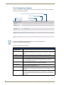
Configuration - Status Page
Port Configuration Options
Click on any of the Port (1-16) links on the Status page (see FIG. 20) to access the Port Configuration
options for the selected Port (FIG. 21):
Click to return all Port Configuration options to default settings
Click to send current settings
to the Receiver
Click to access
Control options
for this port
Port number and
firmware version
FIG. 21 Port Configuration Options
The video compensation options shown in FIG. 21 are only presented when a
Receiver is connected to the selected port.
The Port Configuration Options include:
Port Configuration Options
28
Port Number and
Firmware version:
Displays the currently selected Port (1-16), and the current firmware version.
User Control:
Click to access the User Control options for this Port, to allow Administrators to issue
commands from the UDM WebConsole. See the User Control section on page 36 for
details.
Send Settings To RX:
Click to send the current settings to the UDM Receiver connected to this Port.
Default:
Click to return all Port Configuration options for this Port to their default settings.
Remote Type:
Click to select the type of remote controller to be used for Passthrough control for
this Port (if applicable). See the Passthrough Mode (Inputs A-D, TVM Inputs 14) section on page 40 for details.
Port Name:
The current name for this Port. Click and type in this text field to rename this Port.
See the Renaming Output Ports section on page 29 for details.
Bright Up/Down
Once any skew has been eliminated the video should be adjusted for brightness
using a grey scale or equivalent test card.
Sharp Up/Down
The sharpness of the video should be adjusted last, to eliminate any over or under
shoot of the video. Horizontal black and white bars are one useful method of tuning
sharpness.
Sync:
Click to select a sync mode for this port. Options include: Common, Auto, On Green,
Negative and Positive). By default "Common" sync is selected - in most situations
the sync mode should not be changed unless there are sync issue with a particular
display device.
UDM-1604C 4x16 Multi-Format Distribution Hub
Configuration - Status Page
Port Configuration Options (Cont.)
Red/Green/Blue skew: Use this set of radio buttons to manually add skew delay to any of the video colors.
See the Basic Video Compensation section on page 29 for details.
Protocol:
Select a control protocol to be used for this Port. See the Configuration - Protocols
Page section on page 71 for details.
Renaming Output Ports
1. Click on the relevant Port hyperlink on the Status page (see FIG. 20 on page 27) to invoke the Port
Configuration options for the selected Port (see FIG. 21 on page 28).
2. Type directly into the Name text field to rename the port.
Video Compensation
Options within the Port Configuration page (see FIG. 21 on page 28) allow you to compensate (tune)
outgoing video signals for optimum picture quality.
LCD screens have a tendency to automatically try and compensate the video,
presenting issues when adjusting for skew. Using a CRT monitor to adjust video
quality is often the best way around this.
Basic Video Compensation
1. On the Status page. click on a Port hyperlink to access the Port Configuration options (see
FIG. 21 on page 28).
2. Adjust Brightness and Sharpness via the Up and Down links.
3. To add skew delay into any of the video colors, click on the appropriate color hyperlink (FIG. 22).
1
2
3
FIG. 22 Skew controls
The skew delay cycles through red, green and blue.
Each radio button is equivalent to 2ns delay.
UDM-1604C 4x16 Multi-Format Distribution Hub
29
Configuration - Status Page
Advanced Video Compensation
To enable advanced video compensation options, click on the Enable advanced options checkbox, in the
Setup page (FIG. 23).
FIG. 23 Setup Page - Enable advanced options checkbox
1. In the Status page, click on a Port link to access the Port Configuration options for the selected Port
(see FIG. 21 on page 28).
2. With the Enable advanced options checkbox selected in the Setup page, the Port Configuration
options include the additional Cable Distance field (FIG. 24):
Click to enable "Dual Output"
mode on this Port
Click to enable "Bright" and "Sharp"
fields for manual adjustments
Enter approximate distance of
the cable run between the UDM
hub and UDM Receiver in meters
FIG. 24 Port Configuration options - with "Enable advanced options" selected in the Setup page
3. In the Cable Distance field, enter the approximate distance of the cable run from the UDM-1604C
to the UDM Receiver (in meters). This value is used to automatically adjust the brightness and
sharpness of the image.
The Cable Distance field is intended primarily for use with VGA cabling in excess of
200 meters (see the Audio & Video Formats/Resolutions/Distance section on
page 14).
4. To make manual adjustments to Brightness and Sharpness, click on the Advanced checkbox (see
FIG. 24) to enable the Bright and Sharp fields (FIG. 25):
30
UDM-1604C 4x16 Multi-Format Distribution Hub
Configuration - Status Page
FIG. 25 Port Configuration options - "Enable advanced options" selected in the Setup page and "Advanced" selected
Video compensation settings can also be configured via hyper terminal session. See
the Advanced Administration section on page 93 for details.
Video Compensation (UDM-RX01/RX02)
Video at the Receive end can be compensated using three main methods;
Using the WebConsole to compensate each port individually in the Status option (see the
Video Compensation section on page 29).
Using the Endeleo Remote Control to compensate video (see the Compensating Video Via the
UDM-RC10 Remote Control section on page 31).
Using a hyper terminal session via the serial connector on the UDM-RX02 (especially
effective when using long runs). See the Advanced Administration section on page 93 for
details.
Compensating Video Via the UDM-RC10 Remote Control
Video can also be compensated using the Endeleo UDM-RC10 IR Engineering Remote Control
(FIG. 26).
Amber LED indicates that UDM-RX02 is in Compensation mode
UDM-RX02
IR RX port
IR03 IR Receiver Module (FG-IR03)
FIG. 26 UDM-RX02 with IR03 IR Receiver Module
1. Ensure the IR03 Endeleo External IR Receiver Module (FG-IR03) is attached to the UDM-RX02 at
the IRRX port (FIG. 26).
2. To enter compensation mode, push the ESC and B buttons on the remote control.
UDM-1604C 4x16 Multi-Format Distribution Hub
31
Configuration - Status Page
3. The amber LED at the Cat5 port on the UDM-RX02 will start to flash, indicating the UDM-RX02 is
in compensation mode.
4. Use the buttons on the remote control to adjust appropriately the following up or down;
Sharpness
Gain
Red, Green and Blue.
5. Once the image displayed is of an acceptable quality, push the A button on the remote control to exit
compensation mode.
The compensation settings will be specific to this UDM-RX02 and stored internally
(for example, if this UDM-RX02 is replaced or swapped out the compensation
settings will travel with the UDM-RX02). It may therefore be necessary to recompensate the UDM-RX02 / replacement UDM-RX02 if this UDM-RX02 is to be
used elsewhere or is being replaced.
Dual Output Mode
With the Enable advanced options checkbox selected in the Setup page (see FIG. 23 on page 30), the
Port Configuration options include the Dual Output checkbox (FIG. 25).
Dual Output mode permits a single input to be viewed as two separate output types. For example a port
could be configured for the dual output of VGA and Component video. This means at the UDM
Receiver, the input could be delivered to two separate display devices.
.
Ensure the correct cabling is in place at the RX to accommodate the 2 separate
signals.
32
UDM-1604C 4x16 Multi-Format Distribution Hub
Configuration - Status Page
Selecting Inputs For Display
1. Each port on the hub has a drop down box, in which will be displayed all of the inputs (as
configured in the Inputs page) available to this particular Port (FIG. 27).
Inputs available to Port 1
FIG. 27 Inputs available for a Port
"Inputs" mean inputs directly connected to the rear of the UDM-1604C (e.g. Inputs AD, or devices connected to IRTx ports 1 – 4.
2. Select the appropriate Input which this port will display.
Selecting Multiple Inputs For Display
An input can be assigned to multiple ports to save administration time.
1. To change more than one port to display a particular input, select the desired input from the drop
down list beside the Included option (FIG. 28).
UDM-1604C 4x16 Multi-Format Distribution Hub
33
Configuration - Status Page
FIG. 28 Included drop-down menu
2. Select the checkboxes beneath the Include column beside the relevant ports which are to display the
input selected in the Included drop-down menu. The selected ports are highlighted in blue
(FIG. 29).
Click to select or deselect all Ports
Click checkboxes to include one or more Ports
FIG. 29 Include checkboxes selected for Ports 1-4 (to include Input "A1")
The Include All link toggles all the Ports to be included on or off.
3. Click on Execute to configure the ports to display the Included input (FIG. 30).
34
UDM-1604C 4x16 Multi-Format Distribution Hub
Configuration - Status Page
Click to set the selected Ports
to use the "Included" input
FIG. 30 Execute button
4. Once the configuration changes are complete, de-select the relevant ports by clicking their
corresponding checkbox in the Include column. The blue highlight disappears, and the specified
Ports are configured to use the Included input - see FIG. 31).
FIG. 31 Ports re-configured to use the "Included" input ("A1")
UDM-1604C 4x16 Multi-Format Distribution Hub
35
Configuration - Status Page
Changing an Input
The input being displayed at a Port can be changed at any time via the Input drop-down menu. To change
multiple ports select/include those ports appropriately.
User Control
Administrators can issue commands directly from the UDM WebConsole, via the User Control options
in the Status page (FIG. 32).
Click to select a command from a list
of supported controls for each Port
Click to access User Control
options for each Port
Click to issue one or two commands
to the selected Port(s)
FIG. 32 User Control options
Commands can be issued in multiple ways:
The Control toolbar located at the bottom of the Status page for the selected port(s).
The Control drop-down options for the relevant port
The User Control options for a selected port (click the relevant Port’s link to access User
Control options).
Schedules are also used to issue commands at a pre-determined time to inputs and
devices. Refer to the Configuration - Schedule Page section on page 57 for details.
36
UDM-1604C 4x16 Multi-Format Distribution Hub
Configuration - Status Page
Issuing Commands To a Selected Port
Ensure the device’s IR commands have been learned by the Hub first. Refer to the
Configuration - Protocols Page section on page 71.
Control of the input is performed in a similar way to changing the input to be displayed. Commands can
either be issued per Input or issued across all or groups of ports.
1. For the Port that you want to issue a command, open the Control drop-down menu, as shown in
FIG. 33.
Click to execute the selected
Command on this Port
Control drop-down menu
FIG. 33 Control drop-down menu
2. Select the required command from the Control drop-down menu.
Where a custom control is required, type in the IR code for the command. Refer to
the Creating and Learning an IR Protocol section on page 74.
3. Once selected, click on Execute (see FIG. 33) to execute the selected command for the relevant
port.
Ensure that an (optional) IR01 Endeleo IR Emitter Module (FG-IR01) is connected to
the Receiver’s IRTX port. Attach it to the Device’s IR sensor before issuing a
command. The IR Emitter transmits the command from the Receiver directly to the
device’s IR sensor.
UDM-1604C 4x16 Multi-Format Distribution Hub
37
Configuration - Status Page
Issuing Commands To Multiple Ports
As with the input selection it is also possible to send multiple control commands to all or selected ports.
Because the control strings are stored in the UDM Receivers, a global command across multiple ports
will allow any range of display devices to be controlled simultaneously.
1. Select the Include checkboxes for the Ports to be changed (use the Include All link to toggle all Ports
to be included on or off). The ports are highlighted in blue.
2. Open the Control drop-down menu for one of the selected Ports, and select the control to be
executed.
3. Click on Execute button (see FIG. 33 on page 37).
It is also possible to control centrally located hardware such as DVD players, using
the "Devices" page. See the Issuing Commands to Centrally Located Devices section
on page 56 for details.
Assigning a Command to an Endeleo UDM-RC02 Remote Control
Ensure the IR command which the UDM-RC02 Remote control will issue has been
learned by the Hub first. Refer to the Protocols and IR learning section of this manual.
1. Click on a Port name to access the Port Configuration options for the selected Port.
2. Click the User Control link (FIG. 34). .
Click to access User Control
options for this Port.
FIG. 34 Port Configuration options for Port 1 - User Control link
Alternatively, click on the "User Control" link for the relevant Port on the main Status
Page (see FIG. 33 on page 37).
This action invokes the User Control options for the selected Port (FIG. 35).
Keys 0 to F represent the keys on the UDM-RC02 Remote Control.
Commands for each Key are selected from the Control drop-down menu (provided for each
Key).
38
UDM-1604C 4x16 Multi-Format Distribution Hub
Configuration - Status Page
FIG. 35 User Control options for Port 1
3. Open the Control drop-down menu for any Key, and select the command which this key on the
UDM-RC02 Remote Control will issue (FIG. 36).
Control drop-down for Key 2
FIG. 36 Control drop-down menu for Key 2
UDM-1604C 4x16 Multi-Format Distribution Hub
39
Configuration - Status Page
Ensure the correct key on the Endeleo Remote corresponds with the correct
command.
4. Select either the Port or Device radio button to specify whether this button on the remote should be
associated with the Port (display device) or an actual Device (e.g. a DVD player added to the system
as a device) when it is pushed.
5. The Endeleo Receiver will now accept the relevant command from the RC02 remote (i.e. Key 2 on
the remote will "Play" the Device (FIG. 37). .
FIG. 37 Port Configuration options for Port 1 (Key 2 set to "Play")
Passthrough Mode (Inputs A-D, TVM Inputs 1-4)
Devices can also be placed into Passthrough Mode. Passthrough Mode allows an Endeleo TVM remote
control to be used to control TV channels being viewed through the UDM-1604C, or devices connected
to the UDM-1604C (e.g. a DVD player). Passthrough Mode is available for Inputs A-D and for TVM
inputs 1-4, as shown in FIG. 38:.
FIG. 38 User Control options (for Port 1) - Passthrough Mode options
The following steps must be taken for Passthrough Mode to function correctly:
1. The Device must be added to the system as an Input.
2. IR emitter (on the correct IR port) at the rear of the UDM-1604C must be connected to the device.
3. The Device must be added to the system as a Device and be assigned its learned protocol.
4. The Device’s Port must be configured for Passthrough Mode.
40
UDM-1604C 4x16 Multi-Format Distribution Hub
Configuration - Status Page
Configuring a Device for Passthrough Mode
The device must to be added to the system as both an Input and as a Device:
1. Cable the device as an input coming into the rear of the chassis (e.g. into Input A as for a normal
input).
2. Add the device as an input in the Inputs option. See the Configuration - Inputs Page section on
page 49 for details.
3. Learn the device’s protocol using IR Learning – refer to the Configuration - Protocols Page section
on page 71 and Advanced Administration section on page 93.
4. Add the device into the Devices option as normal and assign it its IR protocol. See the
Configuration - Devices Page section on page 53 for details.
Ensure the relevant IR emitter port is cabled up to the device also e.g. if the device is
connected to Input A cable IR port 1 to the device, if Input B cable IR port 2 to the
device etc.
Configuring a Port for Passthrough Mode
1. Click on a Port link (in the Status page) to access the Port Configuration options (see FIG. 38 on
page 40).
2. Select the Remote Control that will be used to put the device into passthrough mode from the
Remote type drop-down menu (FIG. 39).
FIG. 39 Remote type drop-down menu
3. Click on the Port’s User Control link in the Status page to access the User Control options for the
selected port, and click on the Passthrough checkbox for the key dedicated to putting the Receiver
into Passthrough Mode (FIG. 40).
4. The device can now be controlled directly at the Receiver end.
UDM-1604C 4x16 Multi-Format Distribution Hub
41
Configuration - Status Page
FIG. 40 Passthrough enabled on Key 1 for Port 1
Passthrough Mode (Inputs TVM-AV1 – TVM-AV4)
Similarly a TVM Input (TVM-AV1 – TVM-AV4) can be configured for Passthrough Mode.
Observe the following guidelines;
Ensure the IR Blaster is connected to the correct IR port at the rear of the UDM Hub. For
example IR Port 1 – which will be associated with Device 1 and input TVM-AV1.
The relevant Device Number is selected to reflect the relevant IR Port (same Device number as
IR port on the rear of the UDM Hub).
Ensure the Device number is associated with the relevant TVM-AV port. For example Device
1 is associated with TVM-AV1.
The protocol for the Device (for example a Sky box) has been learned. Refer to Advanced
Administration in this guide.
Relevant key has been assigned in User Control to enter Passthrough Mode for the TVM-AV
input.
The TVM-AV Input has been enabled for Passthrough Mode.
If a TVM Hub is directly connected to port TVM-AV1 on the UDM Hub and an IR
Blaster connected to IR Port 1 (at the rear of the UDM Hub) is associated with Input
A, then only channel changes will be permitted on the TVM Hub – i.e. NON
Passthrough Mode.
\
42
UDM-1604C 4x16 Multi-Format Distribution Hub
Configuration - Status Page
Using Passthrough Mode
Once a device has been configured for Passthrough Mode the relevant remote control is used to control
the device.
Press the previously configured key on the relevant remote control (UDM-RX01 or Sky remote control)
to enter passthrough mode.
If accessing a Sky Box through passthrough, click on the Sky button on the Sky remote
control. Now use the Sky Remote control as normal. (Press TV on the Sky remote to exit
passthrough mode).
If accessing a DVD player through passthrough, click on the relevant button on the DVD
remote control to play, pause, stop eject etc. Use the DVD Remote control as normal.
If accessing an Endeleo TVM Hub through passthrough, click on the Up or Down channel on
the TVM remote control, to toggle between channels.
Exiting Passthrough Mode
Press any key on the UDM-RC02 remote which is not configured as a control enabled key.
If accessing a Tivo or Sky set-top box press TV on the Tivo or Sky remote.
Locking One or More Ports
Locking an output port to a specific source prevents any user control at that port.
1. On the Status page, select the Locked checkbox beside the relevant port or ports (FIG. 41).
FIG. 41 Locking a port
2. Click on Execute. The port is now locked to that display.
Multiple ports can be locked by clicking on the Include checkbox relevant to the port,
then clicking on Execute to lock the ports.
UDM-1604C 4x16 Multi-Format Distribution Hub
43
Configuration - Status Page
44
UDM-1604C 4x16 Multi-Format Distribution Hub
Configuration - Setup Page
Configuration - Setup Page
Overview
Each Hub must be configured for the correct network environment. It is also possible to view device
information, set this UDM-1604C as the Master Hub in a cascaded system, configure the Hub for the
correct date and time and specify Restore options, via options in the Setup page (FIG. 42):
Device information
Network Configuration
Date / Time Settings
Restore Options
FIG. 42 Setup Page
Device Information
The top portion of the Setup page provides several Device Information items as well as Fan control,
SLIP authentication and an option to enable advanced video compensation controls:
Setup Page - Device Information
Controller firmware: This display-only field indicates the current controller firmware version.
Port:
This display-only field indicates the current port (UDM) firmware version.
Input:
This display-only field indicates the current input firmware version.
HTML
This display-only field indicates the current HTML (WebConsole) version.
Serial number:
This display-only field indicates the unique serial number for this UDM Hub.
Internal temp:
This display-only field indicates the current internal temperature of the unit.
Fans:
These radio buttons allow you to turn off the internal fans. The default setting is "Auto"
(fans will automatically turn on and off based on the internal temperature reading).
Caution: by turning off the fans, the unit may be susceptible to overheating.
Cascade Master:
Click to enable Cascading for this UDM-1604C. Refer to the Cascading Hubs section on
page 79 for details.
Authenticate SLIP:
By default, SLIP authentication is enabled. De-select this option to disable SLIP authentication.
Enable advanced
options:
Enable this option to access the advanced video compensation settings (in the Port Configuration options - see the Advanced Video Compensation section on page 30).
UDM-1604C 4x16 Multi-Format Distribution Hub
45
Configuration - Setup Page
Network Configuration
The UDM-1604C does not support DHCP. Please configure a static IP Address.
The default IP address is: 192.168.0.96
The default UDP Port is: 2008
1. The following Network Configuration options must be configured (FIG. 43):
FIG. 43 Network Configuration options
a. Hub IP Address, Subnet Mask and Default Gateway
b. UDP Port
c. Hub name (maximum of 30 characters).
2. Once the network environment has been configured, click on Update.
All changes are immediate - once the IP address of the hub has been changed
redirect the web browser to the changed address.
Date and Time Configuration
The Setup page is also used to set up the hub date and time, which is used for scheduling (FIG. 44).
FIG. 44 Date and Time Settings
1. Enter the desired values for the current Time and Date.
2. Click on Update when all configuration changes have been completed.
46
UDM-1604C 4x16 Multi-Format Distribution Hub
Configuration - Setup Page
Restoring Hub Configuration and Connections
To ensure the configuration settings for the Hub are retained each time the hub boots it is advisable to
ensure the Restore options at the bottom of the Setup page have been enabled (FIG. 45).
FIG. 45 Restore options
Failure to select the Restore Configuration and Connection options will mean if the
Hub is reset the Hub configuration and connections will need to be re-configured.
Restoring Configuration and Connections
To ensure network configuration and port configuration are restored on boot up select Restore
configuration on power up option (see FIG. 45).
Restoring Connections On Power Up
To ensure inputs are transmitted to the outputs (or ports) on boot up select the Restore connections on
power up option (see FIG. 45).
Resetting the UDM-1604C
Where appropriate the Hub can be reset from the Browser interface. Use the Setup option to reset the
Hub.
1. Click the Reset Hub button (see FIG. 45).
The UDM-1604C’s network connection will be lost temporarily and video displays will switch off
then on again very quickly.
2. Restart the Hub.
A power down of the Hub must be performed to complete the reset procedure.
UDM-1604C 4x16 Multi-Format Distribution Hub
47
Configuration - Setup Page
48
UDM-1604C 4x16 Multi-Format Distribution Hub
Configuration - Inputs Page
Configuration - Inputs Page
Overview
Use the options in the Inputs page (FIG. 46) to set up the video types and audio sources being presented
to each input port and where appropriate renaming these.
Configure Video Inputs A-D
Configure TVM Inputs 1-4
Configure Audio Inputs A-D
FIG. 46 Inputs Page
Configuring Inputs A-D
1. For each Input port (A-D), select the Cascade checkbox, if that input will be cascaded from an
upstream UDM-1604C Hub (see the Cascading Hubs section on page 79 for details).
2. For each Input port, select the appropriate input type from the Type drop-down menu provided for
each Input (FIG. 47).
Type drop-down menus
(Input A shown)
FIG. 47 Inputs page - Input Type drop-down menu
For RGB, VGA, Component or SVideo inputs, only one connection is possible per
input port.
3. To name the Input Type, type directly into the Name field for each Input (FIG. 48).
UDM-1604C 4x16 Multi-Format Distribution Hub
49
Configuration - Inputs Page
Name fields for Inputs A-D
Note that since Input B is set to Composite,
there is separate Name field for each
composite input
FIG. 48 Inputs page - Naming the Input Type
If the Input Type is Composite, additional Name fields are provided to name each of the 3
composite sources separately (as shown in FIG. 48). Name each Composite video source
appropriately.
Configuring TVM (AV) Inputs
TV Inputs from an Endeleo TVM hub can also be fed into the UDM-1604C for display at screens
throughout the location.
The power at the relevant TVM port will have to be disabled using the <k> <port no>
command or through the TVM’s WebConsole before being connected to a UDM Hub.
Configuring TVM inputs for a UDM Hub
1. Ensure the port on the TVM is configured to display the correct channel (refer to the TVM
documentation).
2. Ensure the power on the TVM port which will transmit the TV feed has been switched off using the
[k] [port no] command (or using the TVM’s WebConsole).
3. Connect a Cat5 cable from the TVM port on the front panel of the UDM-1604C (FIG. 49) to the
relevant TVM port on the front of the UDM Hub.
TVM (AV) Inputs
FIG. 49 TVM (AV) inputs
4. Name each TVM input accordingly (FIG. 50).
50
UDM-1604C 4x16 Multi-Format Distribution Hub
Configuration - Inputs Page
Default channel on the TVM
when this input is selected
Name each TVM
input here
FIG. 50 Configuring TVM inputs for a UDM-1604C
5. Configure the default channels for each TVM input. For example if you enter "1" in the text field for
TVM-AV1 (as shown in FIG. 50), then every time a UDM user selected TVM-AV1 then they would
be initially switched through to TV channel 1.
Channel names are manually entered to help the user recognize each input from the input selection
drop down box on the Status page.
If through the user selection page you have enabled pass through (i.e. the ability for
the user to send commands through to the TVM hub to change the channel), then
you may find that the text no longer reflects channel being viewed. If this feature is to
be used, try using a generic channel name such as "TVM port X".
Configuring Audio Types For Inputs
Audio types (Analog L/R or S/PDIF) can be configured for each Input. In the audio section, under the
Type column, select the type of audio (Analog L/R, S/PDIF or none) for each input (FIG. 51).
FIG. 51 Configuring audio types for inputs
Ensure audio has been connected from the Input to the rear of the hub. Ensure the
connections are sound and fixed correctly.
UDM-1604C 4x16 Multi-Format Distribution Hub
51
Configuration - Inputs Page
52
UDM-1604C 4x16 Multi-Format Distribution Hub
Configuration - Devices Page
Configuration - Devices Page
Overview
The system allows "centrally located" devices connected to the rear of the UDM-1604C (e.g. VCR,
DVD, DVR or Satellite Decoders) to be managed from the user port. Centrally located devices are
connected directly to the rear of the UDM-1604C via the UDM IR ports (Tx1 – Tx4) using an Endeleo
IR Tx bud.
The IR Tx bud will then transmit the IR signal from the UDM-1604C to the device.This is performed
through the Devices page (FIG. 52).
FIG. 52 Devices page
An IR02 Endeleo IR Splitter Cable (FG-IR02) will be needed for each of the IR ports if using 2 devices
per IR port.
If only one device connected to IR TX port 1/2 it will by default be Device 1.
If only one device connected to IR TX port 3/4 it will by default be Device 3.
IR TX Ports 1/2
IR TX Ports 3/4
FIG. 53 IR TX ports for locally connected devices
UDM-1604C 4x16 Multi-Format Distribution Hub
53
Configuration - Devices Page
Adding Centrally Located Devices
1. Name each device accordingly by typing in the Name text fields.
Ensure the correct port is selected.
2. Configure the device with the relevant IR protocol if appropriate.
Refer to the Creating and Learning an IR Protocol section on page 74 for details.
Issuing Commands To a Centrally Located IR Device
The UDM-1604C needs to learn the device’s IR protocol (which button on its remote
performs which function). Refer to the Configuration - Protocols Page section on
page 71.
1. The Control toolbar at the bottom of the screen enables specific commands to be executed via the
browser connection (FIG. 54).
FIG. 54 Control Bar
2. Select the command(s) to be performed for this device from the 1st and 2nd (Command) drop-down
menus (FIG. 55). Two commands can be issued to a device (1st and 2nd).
FIG. 55 Optional controls for a device
The first command is limited to Power On, Off and A/V Select.
3. Click the Include checkbox to select the device(s) to be sent a command.
54
UDM-1604C 4x16 Multi-Format Distribution Hub
Configuration - Devices Page
4. Click the Send to Included link to send the selected command to the Included device(s).
Alternatively such commands can be scheduled to occur later. Refer to the
Configuration - Schedule Page section on page 57 for details.
Custom Commands
Custom Commands permits the Administrator to specify custom IR commands which can sent to the
device or display. A list of custom commands and their IR value can be found in the Endeleo IR
Codes section on page 103).
To issue a custom command;
1. Select the custom option within the 2nd list of commands.
2. Type in the value of the IR code which is to be sent in the relevant box.
3. Execute the custom command or schedule it to occur later.
UDM-1604C 4x16 Multi-Format Distribution Hub
55
Configuration - Devices Page
Issuing Commands to Centrally Located Devices
It is also possible to control centrally located hardware such as DVD players, via options in the Devices
page. Remember an IR-TX bud coming from the rear of the UDM-1604C will sit over the Device’s IR
sensor.
1. Select the device(s) you wish to control by clicking on the appropriate Include checkboxes
(FIG. 56).
FIG. 56 Selected devices
2. In the Control toolbar at the bottom of the page, select the command(s) to be performed for the
selected device(s) from the 1st and 2nd (Command) drop-down menus (FIG. 55). Two commands
can be issued to a device (1st and 2nd).
FIG. 57 Optional controls for a device
The first command is limited to Power On, Off and A/V Select.
3. Click the Send to included link to issue the commands (see FIG. 57).
The Device’s commands must have been learned by the UDM-1604C in order to
function. Refer to the Configuration - Protocols Page section on page 71.
56
UDM-1604C 4x16 Multi-Format Distribution Hub
Configuration - Schedule Page
Configuration - Schedule Page
Overview
The UDM-1604C features an on-board clock that allows you to create scheduled events to be executed at
a predetermined time in the future. Scheduled events are listed on the Schedule page (FIG. 58), but are
created using options in both the Status and Devices pages, as described in this section.
FIG. 58 Schedule page
You can create and store up to 16 scheduled events.
There are several basic types of scheduled events:
Scheduled IR Device Controls - Use the Schedule options in the Devices page to schedule
events to be executed at specified times on IR-controlled devices connected to the IRTX (IR
Transmit) Ports on the rear panel (see the IRTX (IR Transmit) Ports section on page 13). For
example, you could create a scheduled device event that causes the devices connected to TX
Ports 1-4 to power-up and/or power-down at scheduled times each day.
See the Scheduling IR Device Control Events section on page 58 for details.
Scheduled Output Device Control - Use the Schedule options in the bottom toolbar of the
Status page to schedule events to be executed at specified times on display devices connected
to the RJ-45 Output ports on the front panel (see the OUTPUT Ports (RJ-45) section on
page 9). For example, you could create a scheduled port control event that causes the display
devices connected to Outputs 1-4 to power-up and/or power-down at scheduled times each
day.
See the Scheduling Output Device Control Events section on page 61 for details.
UDM-1604C 4x16 Multi-Format Distribution Hub
57
Configuration - Schedule Page
Scheduled Input Controls - Use the Schedule options in the top toolbar of the Status page to
schedule inputs (devices connected to the Input connectors on the rear panel of the UDM) to
be displayed on specific Ports (via the UDM receivers connected to the Output ports on the
front of the UDM) at specified times. For example, you could create a scheduled input event
that causes the device connected to Input A to automatically display on Port 1 every day at
9:00am.
See the Scheduling Inputs section on page 64 for details.
Preset Scheduling - Multiple scheduled events can be combined into a single Preset
Schedule. For example, you could create a Preset Schedule that powers up devices 1-4
(connected to the IRTX Ports on the rear panel), then powers up display devices 1-4
(connected to the RJ-45 Output ports on the front panel), and displays Inputs 1-4 on Ports 1-4.
See the Preset Scheduling section on page 67 for details.
Checking the Hub Time
Click on the date and time at the top-right of the Status page to refresh the UDM’s internal clock to the
current time (FIG. 59). This can be useful before creating a scheduled event.
FIG. 59 Hub Date and Time
Scheduling IR Device Control Events
Use the Schedule options in the Devices page (bottom toolbar) to create a scheduled IR Device Control
Event (FIG. 60):
IR Device Control toolbar
FIG. 60 Devices page
58
UDM-1604C 4x16 Multi-Format Distribution Hub
Configuration - Schedule Page
1. Select up to two commands to be executed from the 1st and 2nd Control drop-down menus at the
bottom of the Devices page (FIG. 61).
Select command #1
Select command #2
FIG. 61 Commands to be executed
2. Select the device(s) to which the command should be sent by clicking on the relevant Include
checkboxes (FIG. 62).
FIG. 62 Devices 1 and 2 selected to receive the specified controls
To test the selected commands with the selected Ports, click on the Send To Included link at the
bottom of the Devices page (FIG. 63). Note that clicking here sends the commands to the selected
Ports, but does not schedule the commands,
FIG. 63 Send To Included link
UDM-1604C 4x16 Multi-Format Distribution Hub
59
Configuration - Schedule Page
3. Click the Schedule link at the bottom of the Devices page to schedule the specified commands for
the selected Devices (FIG. 64).
FIG. 64 Schedule link
4. This invokes the Schedule page. The command(s) and Port(s) selected in the Status page will
automatically appear in the scheduled event (FIG. 65).
Enter name for scheduled event here
commands
Ports
FIG. 65 Schedule page (indicating "Pwr On" and "Play" commands, and Ports 1 and 2
5. Name the scheduled event in the text field provided.
6. In the Frequency drop-down menu, select a frequency for the scheduled event, and enter the time for
the event to occur in the text fields provided (FIG. 66).
Enter a time for the scheduled event here
Select a frequency for
the scheduled event
FIG. 66 Selecting the event frequency and time
Refer to the Scheduling Events - Frequency Options section on page 68 for a
description of each frequency option.
7. Click the Add link (see FIG. 66) to add the schedule to the list of scheduled events (FIG. 67).
FIG. 67 Scheduled event added
8. Click the event’s Enabled checkbox (FIG. 68).
Enabled Scheduled Event
FIG. 68 An enabled schedule
Once enabled, the scheduled event will execute at the specified time/frequency.
60
UDM-1604C 4x16 Multi-Format Distribution Hub
Configuration - Schedule Page
Scheduling Output Device Control Events
Use the Schedule options in the bottom toolbar of the Status page to schedule events to be executed at
specified times on display devices connected to the RJ-45 Output ports on the front panel (FIG. 69).
Output Device Control toolbar
FIG. 69 Status page
1. Select up to two commands to be executed from the 1st and 2nd Control drop-down menus at the
bottom of the Status page (FIG. 70).
Select command #1
Select command #2
FIG. 70 Commands to be executed
UDM-1604C 4x16 Multi-Format Distribution Hub
61
Configuration - Schedule Page
2. Select the Port(s) to which the command should be sent by clicking on the relevant Include
checkboxes (FIG. 71).
FIG. 71 Devices 1 - 4 selected to receive the specified controls
3. Click the Schedule link at the bottom of the Status page to schedule the specified commands for the
selected Devices (FIG. 72).
FIG. 72 Schedule link
4. This invokes the Schedule page. The commands(s) and Port(s) selected in the Status page will
automatically appear in the scheduled event (FIG. 73).
Enter name for scheduled event here
commands
Ports
FIG. 73 Schedule page (indicating "Pwr On" and "Play" commands, and Ports 1 and 2
5. Name the scheduled event in the text field provided.
6. In the Frequency drop-down menu, select a frequency for the scheduled event, and enter the time for
the event to occur in the text fields provided (FIG. 74).
62
UDM-1604C 4x16 Multi-Format Distribution Hub
Configuration - Schedule Page
Enter a time for the scheduled event here
Select a frequency for
the scheduled event
FIG. 74 Selecting the event frequency and time
Refer to the Scheduling Events - Frequency Options section on page 68 for a
description of each frequency option.
7. Click the Add link (see FIG. 74) to add the schedule to the list of scheduled events (FIG. 75).
FIG. 75 Scheduled event added
8. Click the event’s Enabled checkbox (FIG. 76).
Enabled Scheduled Event
FIG. 76 An enabled schedule
Once enabled, the scheduled event will execute at the specified time/frequency.
UDM-1604C 4x16 Multi-Format Distribution Hub
63
Configuration - Schedule Page
Scheduling Inputs
Use the Schedule link in the top toolbar of the Status page to schedule Inputs to be displayed on specific
Ports at specified times (FIG. 77).
Inputs Control toolbar
FIG. 77 Status page
1. In the Status page, select the Inputs to which the schedule will be applied from the Included dropdown menu (FIG. 78).
FIG. 78 Included drop-down menu (Status page)
64
UDM-1604C 4x16 Multi-Format Distribution Hub
Configuration - Schedule Page
2. Select the Ports on which the input will be displayed by clicking on the Include checkbox at the
relevant ports. The selected ports are highlighted in blue (FIG. 79).
FIG. 79 Selecting the ports on which the input will be displayed
3. Click on the Schedule link at the top of the page (FIG. 80).
FIG. 80 Click the top Schedule link to access the Schedule page
4. This invokes the Schedule page. The Input(s) and port(s) selected in the Status page will
automatically appear in the scheduled event (FIG. 81).
UDM-1604C 4x16 Multi-Format Distribution Hub
65
Configuration - Schedule Page
Input
Ports
Enter name for scheduled event here
Preset toolbar
FIG. 81 Schedule page (indicating Input "A1" and Ports 1 and 2
5. Name the scheduled event in the text field provided.
6. In the Frequency drop-down menu, select a frequency for the scheduled event, and enter the time for
the event to occur in the text fields provided (FIG. 82).
Enter a time for the scheduled event here
Select a frequency for
the scheduled event
FIG. 82 Selecting the event frequency and time
Refer to the Scheduling Events - Frequency Options section on page 68 for a
description of each frequency option.
7. Click the Add link (see FIG. 82) to add the schedule to the list of scheduled events (FIG. 83).
FIG. 83 Scheduled event added
66
UDM-1604C 4x16 Multi-Format Distribution Hub
Configuration - Schedule Page
8. Click the event’s Enabled checkbox (FIG. 84).
Enabled Scheduled Event
FIG. 84 An enabled schedule
Once enabled, the scheduled event will execute at the specified time/frequency.
Each new scheduled event is displayed on the Schedule page.
Preset Scheduling
It is possible to create a scheduled Preset (or Combination) event - events based on schedules already
created (such as combining two or more existing events), via options in the Schedule page.
1. In the Schedule page (which displays a listing of all currently scheduled events), click each
schedule’s Preset link (FIG. 85).
FIG. 85 Schedule page - Preset links
2. The individual scheduled event numbers appear in the Preset toolbar at the bottom of the page
(FIG. 86).
3. Specify a frequency for the Preset event by selecting from the Frequency drop-down menu
(FIG. 86).
4. Enter a Time for the Preset event by typing directly into the text fields provided (FIG. 86).
Enter Preset name
Schedule numbers
Select frequency
Enter time
Add Preset event
FIG. 86 Schedule page - Preset toolbar
The Frequency and Time specified here overrides any previously created frequency /
times used in the Preset schedule.
5. If an interval is required between each individual schedule within the Preset schedule, specify a time
interval (in seconds) in the Interval field (FIG. 86).
6. Assign the Preset schedule a unique name by replacing the default text (FIG. 86).
7. Finally click the Add hyperlink button. The Preset event should now appear in the event list.
UDM-1604C 4x16 Multi-Format Distribution Hub
67
Configuration - Schedule Page
8. Enable the event also by clicking on the tick box beneath the Enable column beside the
combination event (FIG. 87).
Enabled Scheduled Event
FIG. 87 Enabling a Preset schedule
No tick box appears to the left of the combined event as several combined events can
not be added together.
Scheduling Events - Frequency Options
A scheduled event can execute in a number of ways, according to the frequency option selected in the
Frequency drop-down menu:
Scheduled Events - Frequency Options
Hour
Event happens at a specified time and then every 60 minutes.
Day
Event happens at a specified time and then every 24 hours.
Weekday
Event happens at a specified time and then every 24 hours
(Monday through Friday).
Sunday
Event happens every Sunday at specified time.
Monday-Saturday As with Sunday.
Configuring the UDM-RC02 Remote Control for Scheduling
Ensure the relevant schedules have been defined before assigning schedules to the
UDM-RC02 Remote Control.
1. In the Status page, click the appropriate Port name hyperlink to access the Port Configuration
options shown in FIG. 88:
FIG. 88 Port Configuration options
68
UDM-1604C 4x16 Multi-Format Distribution Hub
Configuration - Schedule Page
2. Click on the User Control link at the top right of the page (see FIG. 88). This invokes the Control
Options page for the selected Port (FIG. 89).
FIG. 89 Control Options page
3. Keys 0 to F represent the keys on the UDM-RC02 Remote Control. For each Key, select the
schedule (from the Schedule drop-down menu) to be issued by the selected Key on the UDM-RC02
Remote Control (FIG. 90).
For each Device selected, you must specify a
Protocol from the Protocol drop-down menu
(Protocols are not used for Ports)
FIG. 90 Control Options page - Schedule drop-down menu
Ensure the correct key on the UDM-RC02 Remote Control corresponds with the
correct schedule.
4. The Receiver will now accept the relevant command from the UDM-RC02 Remote Control.
UDM-1604C 4x16 Multi-Format Distribution Hub
69
Configuration - Schedule Page
70
UDM-1604C 4x16 Multi-Format Distribution Hub
Configuration - Protocols Page
Configuration - Protocols Page
Overview
Protocols for serial and infrared devices used in the system can be created via options in the Protocols
page. These protocols allow the UDM-1604C to control serial and infrared devices connected via the
Hub. To access the Protocols page from any other Configuration page in the WebConsole, click on the
Protocols link in the navigation pane (FIG. 91).
FIG. 91 Protocols Page
For Serial devices the following information is key to the successful function of the serial device;
Serial cable and pinouts;
Serial settings for correct communication with the device and
Manufacturer’s command strings equivalent to the command to be executed from the
UDM-1604C.
For IR devices the device’s IR controls (remote control key presses) will have to be learned by the
UDM-1604C.
UDM-1604C 4x16 Multi-Format Distribution Hub
71
Configuration - Protocols Page
Creating a Serial Protocol
1. Open the Serial Protocol drop-down menu, and select New (FIG. 92).
FIG. 92 Serial Protocol drop-down menu
This action invokes several additional fields: Name, Settings and Initialise (FIG. 93):
FIG. 93 Creating a new serial protocol
2. Name the serial protocol appropriately and assign the protocol Settings (baud rate and parity).
When configuring the serial settings "OP" means Odd, Parity and "EP" means Even,
Parity.
3. Click on Initialise to clear the UDM Receiver of any pre-loaded serial commands, and invoke the
Action options shown in FIG. 94.
FIG. 94 Creating a serial command for the action
4. Select an Action to be performed from the Action drop-down menu (FIG. 95).
Click to add this Action/Serial command
string to the new Serial protocol
Type the serial command string associated
with the selected Action in this text field
FIG. 95 Creating a serial command for the action
5. Enter the serial command (serial string) equivalent for this action in the Serial command text field.
The serial string which reflects the action has to be accurate for the serial command
to work. Consult the Manufacturer’s web site or documentation to ascertain the
correct string for this serial device.
72
UDM-1604C 4x16 Multi-Format Distribution Hub
Configuration - Protocols Page
6. Click Add to create the new protocol.
7. Repeat if necessary for other serial commands which are to be stored under this protocol name.
Once complete, the protocol can be assigned to relevant devices.
It is presumed that the serial device connected to the Endeleo RX has the
appropriate serial settings as described and the correct serial cable/pinouts
configured in order to function correctly with the Receiver.
Updating the UDM Receiver With the Serial Protocol
The UDM-RX02 Receiver which will issue the relevant serial commands to the device must be
connected to the UDM-1604C’s relevant port (via Cat5/e/6 cable). Once the Serial Protocol and
commands have been created, follow these steps to update the connected UDM Receiver with the new
protocol:
Remember the serial commands are stored within the UDM Receiver.
1. On the Status page (see FIG. 20 on page 27), click on the port number (hyperlink) to which the
serial device is attached. This invokes the Port Configuration options for the selected Port.
It is the Endeleo Receiver which will issue the serial command over the serial cable
connected between the Receiver and the device.
2. Click on the Protocol drop-down menu (FIG. 96).
Select the Serial protocol to
download to the UDM Receiver
connected to this Port
FIG. 96 Port Configuration options - Protocol drop-down menu
3. Select the Serial protocol which this UDM Receiver will download. This may take a few minutes
depending on how many commands are within the protocol.
4. A message will appear saying “Loading Protocol – Please wait”. Once this has disappeared the
Serial protocol has been downloaded to the UDM Receiver. Commands can now be sent from the
Hub WebConsole to the serial device.
UDM-1604C 4x16 Multi-Format Distribution Hub
73
Configuration - Protocols Page
A new table for this device’s Serial control is what is actually being created. When the
administrator decides to create further commands particular to this serial device they
will be stored within this table e.g power off, power on. If new commands are to be
created in future ensure the correct Serial Protocol has been selected before defining
new commands to ensure commands are stored in the correct table. There is one
protocol/table per UDM Receiver.
Creating and Learning an IR Protocol
IR protocols can be learned by the UDM-1604C by using the device’s remote control to program its
commands into the UDM-1604C. This is performed via options in the Protocols page.
The device’s own remote control can still be used locally at the device to control the
device.
The UDM-1604C can learn between 8 and 25 IR commands, depending on the command length and
protocol used.
IR Learning with a Device’s Remote Control
1. In the Protocol page, open the IR protocol drop-down menu, and select New (FIG. 97).
FIG. 97 IR Protocol drop-down menu
This action invokes two additional fields: Name and Initialise (FIG. 98):
FIG. 98 Creating a new IR protocol
2. Name the IR protocol appropriately, and click on Initialise.
3. Select the action which is to be performed from the Action drop down menu (e.g. vol up - FIG. 99).
FIG. 99 IR protocol - Action drop-down menu
74
UDM-1604C 4x16 Multi-Format Distribution Hub
Configuration - Protocols Page
Ensure the device’s remote control is pointing to the IR sensor located at the front of
the UDM-1604C when performing key presses. If not the key presses may not be
stored in the UDM-1604C.
4. Click on Step 1 (FIG. 100).
FIG. 100 Capturing IR Protocol - Step 1
5. A message saying Press key on remote will appear (FIG. 101).
FIG. 101 Capturing IR Protocol - "Press key on remote"
6. Click the key on the device’s remote control which will manage the action Power On.
7. Click on Step 2 to repeat the process for this command.
8. A message saying Press key on remote will appear. Click the key on the device’s remote control
which will manage the action Power On.
The IR learning process requires that the command on the device’s remote is learned
twice (i.e the same remote control command needs to be repeated at Step 2).
Updating the UDM Receiver With the IR Protocol
A UDM-RX01/02 Receiver, which will issue the relevant IR commands to the device,
must be connected to the relevant port via a Cat5/e/6 cable. Remember the IR
commands are stored within the Receiver.
1. Ensure the Infrared Protocol has been created previously.
2. Click on the Status page.
3. Click on the port number hyperlink which the device is attached to. It is the Receiver which will
transmit the IR command to the devices IR interface.
4. Once the port properties become visible click on the arrow to the right of the Protocol field.
5. Select the IR protocol which this Receiver will download. This may take a few minutes depending
on how many commands are within the table.
6. A message will appear saying “Loading Protocol – Please wait” once this has disappeared the IR
protocol has been downloaded to the RX device. IR commands can now be sent from the Hub Web
pages to the device.
UDM-1604C 4x16 Multi-Format Distribution Hub
75
Configuration - Protocols Page
Testing Serial Control Commands
Device serial codes can be tested via options in the Status page, before they are added to the protocol
library.
Serial commands are stored in the UDM-RX02, and care should be taken to keep any
serially programmed units associated with the correct display device type.
The UDM-RX02 can store approximately eight serial commands per device, depending on the length of
the serial string.
1. On the Status page. click on a Port hyperlink to access the Port Configuration options.
2. In the Protocol drop-down menu, select Serial to enable the Serial-specific configuration options
shown in FIG. 102.
Select Baud Rate
Select Parity
Click to initialize the UDM-RX02
Enter Serial command string
Test the entered command
FIG. 102 Serial configuration options
Any serial protocols that have been created previously are also available via this
drop-down menu. Refer to the Creating and Learning an IR Protocol section on
page 74 for details.
3. Select the appropriate Baud Rate and Parity settings from the drop-down menus.
4. Click on Initialize to initialize the UDM-RX02.
5. Enter the serial string equivalent to perform the desired control function in the Serial Command text
field (see FIG. 102).
The UDM-1604C supports a predetermined set of actions (commands), against which you can
associate serial strings. For a listing of supported commands, check the Control drop-down menu.
Either enter ASCII text directly into the serial command box or where a HEX code is required.
Precede the double-digit HEX code with a “%” symbol.
The example below (FIG. 103) is from a Panasonic screen where the actual command string
requires a “Start of Text” header (stx), the character command POF (Power Off) and a “End of Text”
header (etx).
Both the headers have therefore been added in HEX and the character string uses ASCII.
FIG. 103 Panasonic screen - command screen
6. Once you have finished entering the string you can test that it operates as expected, via the Test
hyperlink. This sends the string typed into the Serial Command text box to the device connected.
Repeat the process as many times as required to test a complete set of controls before saving them to the
protocol library.
76
UDM-1604C 4x16 Multi-Format Distribution Hub
Configuration - Protocols Page
Examples of Serial Controls
Screen Type
Command
Ascii code
Hex code
NEC 30/40” LCD
Power Off
00!%0D
%00%00%21%0D
Power On
00”%0D
Panasonic
%00%00%22%0D
CVBS Input Select 00_v1%0D
%00%00%5f%76%31%0D
DSR
Data Set Ready
Power Off
%02POF%03
%02%50%4F%46%03
The video mode select commands (VGA select etc.) are extremely useful commands and enable a serial
string to be associated with a change of input type, allowing a display automatically switched to the
appropriate input port on a change of the video type from the UDM-1604C.
See the Ascii / Hex Conversion section on page 117 for details.
Deleting Protocols
Protocols can be deleted individually by type (Delete) or all protocols can be removed from the UDM1604C (Delete all) i.e. all serial and all Infrared protocols can be deleted using Delete All.
1. Click on the Protocols option.
2. To delete a protocol click the Delete hyperlink in the serial section to delete a serial protocol or click
the Delete hyperlink in the Infrared section to delete an infrared protocol.
The last created or currently highlighted serial or infrared protocol will be deleted
when using the Delete hyperlink.
Deleting All Protocols (Serial and IR)
All protocols can be deleted from the UDM-1604C.
1. Click on the Protocols option.
2. To delete all protocols click the Delete all hyperlink in the Serial section i.e. the top half of the
screen. This deletes all Serial and all Infrared protocols.
UDM-1604C 4x16 Multi-Format Distribution Hub
77
Configuration - Protocols Page
78
UDM-1604C 4x16 Multi-Format Distribution Hub
Cascading Hubs
Cascading Hubs
Distributing Video - Using Cascade Kits
To ensure that customers are satisfied with the operation of the UDM-1604C even as video resolutions
increase, AMX recommends that ALL new installations of the UDM-1604C requiring cascade capability
use kit FG1402-61K or kit FG1402-62K as an alternative to the cascade ports built into the
UDM-1604C. These Cascade kits use Solecis Distribution Amplifiers (rather than the Cascade ports) to
distribute Video.
This will offer the best video performance without compromising any flexibility, and should be used for
all video types (Composite, S-Video, Component, RGBHV).
For all new installations, the CASCADE connectors should only be used to cascade
audio. See the Cascading Audio section on page 88 for details.
Each Solecis Distribution Amplifier distributes one video source to up to six target devices (in this case,
UDM-1604C Hubs).
Compatible Solecis Distribution Amplifiers include:
Solecis Distribution Amplifiers
Product Name
Description
FG#
AVB-DA-RGBHV-0102
1x2 RGBHV HD-15 Distribution Amplifier
FG1340-1200-01
AVB-DA-RGBHV-ST-0102
1x2 RGBHV HD-15 Stereo Distribution Amplifier
FG1340-1101-02
AVB-DA-RGBHV-0103
1x3 RGBHV BNC Distribution Amplifier
FG1340-3403-01
Note: This DA requires a BNC-to-HD-15 adapter
cable to connect to the UDM-1604C.
AVB-DA-RGBHV-0104
1x4 RGBHV HD-15 Distribution Amplifier
FG1340-3404-01
AVB-DA-RGBHV-0106
1x6 RGBHV BNC Distribution Amplifier
FG1340-4516-01
Note: This DA requires a BNC-to-HD-15 adapter
cable to connect to the UDM-1604C.
AVB-DA-RGBHV-HD15-0106
1x6 RGBHV HD-15 Distribution Amplifier
FG1340-4616-01
Refer to each Solecis Distribution Amplifier Installation Guide for detailed product
specifications and installation instructions.
The examples and figures in this section use the Solecis AVB-DA-RGBHV-0104 1x4 RGBHV HD-15
Distribution Amplifier (FG1340-3404-01).
UDM-1604C 4x16 Multi-Format Distribution Hub
79
Cascading Hubs
Using Solecis Distribution Amplifiers to Distribute Video
1. Connect the video output from each source A/V device to the VIDEO INPUT connector on the
Solecis Distribution Amplifier (DA). Each source A/V device should be connected to a Solecis
(DA).
2. Connect the VIDEO OUTPUT connectors on the Solecis DA to the VIDEO IN connectors on each
UDM-1604C.
The illustration in FIG. 104 shows all four video outputs on the Solecis DA connecting to Video Input A,
on four UDM-1604C Hubs.
SOURCE 1
AVB-DA-RGBHV-0104
INPUT
OUTPUT 1 OUTPUT 2 OUTPUT 3 OUTPUT 4
UDM-1604C
A
B
C
D
VIDEO IN
VIDEO IN
VIDEO IN
VIDEO IN
A
B
C
D
UDM-1604C
VIDEO IN
VIDEO IN
VIDEO IN
VIDEO IN
A
B
C
D
UDM-1604C
VIDEO IN
VIDEO IN
VIDEO IN
VIDEO IN
A
B
C
D
UDM-1604C
VIDEO IN
VIDEO IN
VIDEO IN
VIDEO IN
FIG. 104 Using Solecis Distribution Amplifiers to Distribute Video
80
UDM-1604C 4x16 Multi-Format Distribution Hub
Cascading Hubs
FIG. 105 illustrates the video connection layout for a system using four source A/V devices, four Solecis
DAs, and four UDM-1604C Hubs (Master Hub plus three Target Hubs):
SOURCE 1
SOURCE 2
AVB-DA-RGBHV-0104
INPUT
OUTPUT 1 OUTPUT 2 OUTPUT 3 OUTPUT 4
A
VIDEO IN
SOURCE 3
AVB-DA-RGBHV-0104
INPUT
AVB-DA-RGBHV-0104
OUTPUT 1 OUTPUT 2 OUTPUT 3 OUTPUT 4
B
C
VIDEO IN
SOURCE 4
INPUT
AVB-DA-RGBHV-0104
OUTPUT 1 OUTPUT 2 OUTPUT 3 OUTPUT 4
INPUT
OUTPUT 1 OUTPUT 2 OUTPUT 3 OUTPUT 4
D
VIDEO IN
VIDEO IN
UDM-1604C
A
VIDEO IN
B
C
VIDEO IN
D
VIDEO IN
VIDEO IN
UDM-1604C
A
VIDEO IN
B
C
VIDEO IN
VIDEO IN
D
VIDEO IN
UDM-1604C
A
VIDEO IN
B
VIDEO IN
C
VIDEO IN
D
VIDEO IN
UDM-1604C
FIG. 105 Video Distribution System
UDM-1604C 4x16 Multi-Format Distribution Hub
81
Cascading Hubs
Distributing Video - Cascading One UDM-1604C Hub
FIG. 106 illustrates an A/V distribution system using two Solecis DAs to distribute video, and one target
UDM-1604C Hub to cascade audio to (up to) 32 display devices (16 outputs per UDM-1604C Hub):
SOURCE 1
Video
INPUT
SOURCE 2
Audio
Video
AVB-DA-RGBHV-0104
OUTPUT 1 OUTPUT 2 OUTPUT 3 OUTPUT 4
A
VIDEO IN
INPUT
Audio
AVB-DA-RGBHV-0104
OUTPUT 1 OUTPUT 2 OUTPUT 3 OUTPUT 4
B
C
VIDEO IN
Master Hub
VIDEO IN
UDM-1604C
Cascade Cable
(cascading Audio only)
A
VIDEO IN
B
VIDEO IN
C
Target Hub
VIDEO IN
UDM-1604C
Each UDM-1604C distributes video via
UDM-RX01/02/02N Receivers connected
to the RJ45 OUTPUT Ports on the front
panel of the UDM-1604C Hub
16 UDM Receivers
to display
devices
16 UDM Receivers
to display
devices
UDM-RX01/02/02 Receivers
(up to 16 per UDM-1604C)
FIG. 106 Cascading One UDM-1604C Hub (using Video Distribution)
82
UDM-1604C 4x16 Multi-Format Distribution Hub
Cascading Hubs
Distributing Video - Cascading Two UDM-1604C Hubs
FIG. 107 illustrates an A/V distribution system using three Solecis DAs to distribute video, and two
target UDM-1604C Hubs to cascade audio to (up to) 48 display devices (16 outputs per UDM-1604C
Hub):
SOURCE 1
Video
INPUT
SOURCE 2
Audio
Video
AVB-DA-RGBHV-0104
OUTPUT 1 OUTPUT 2 OUTPUT 3 OUTPUT 4
A
VIDEO IN
INPUT
SOURCE 3
Audio
Video
AVB-DA-RGBHV-0104
OUTPUT 1 OUTPUT 2 OUTPUT 3 OUTPUT 4
B
C
VIDEO IN
VIDEO IN
INPUT
Audio
AVB-DA-RGBHV-0104
OUTPUT 1 OUTPUT 2 OUTPUT 3 OUTPUT 4
D
VIDEO IN
Master Hub
UDM-1604C
Cascade Cable
(cascading Audio only)
A
VIDEO IN
B
C
VIDEO IN
VIDEO IN
D
Target
Hub #1
VIDEO IN
UDM-1604C
Cascade Cable
(cascading Audio only)
A
VIDEO IN
B
VIDEO IN
C
VIDEO IN
D
Target
Hub #2
VIDEO IN
UDM-1604C
Each UDM-1604C distributes video via
UDM-RX01/02/02N Receivers connected
to the RJ45 OUTPUT Ports on the front
panel of the UDM-1604C Hub
16 UDM Receivers
to display
devices
16 UDM Receivers
to display
devices
16 UDM Receivers
to display
devices
UDM-RX01/02/02 Receivers
(up to 16 per UDM-1604C)
FIG. 107 Cascading Two UDM-1604C Hubs (using Video Distribution)
UDM-1604C 4x16 Multi-Format Distribution Hub
83
Cascading Hubs
CASCADE IN/OUT Connectors
The CASCADE IN and OUT connectors on the UDM-1604C require a UDM-EXP-01 50-Pin Hub
Expansion Cable (FG-UDM-EXP01 - not included). The CASCADE IN and OUT connectors on the
UDM-1604C are intended to be used for cascading audio only.
From another UDM Hub
To another UDM Hub
FIG. 108 Cascade In/Out Ports
For all new installations, the recommended method for video distribution uses Solecis
Distribution Amplifiers, rather than the CASCADE IN/OUT Ports (see the Distributing
Video - Using Cascade Kits section on page 79).
Cascaded Hub Connection Diagrams
FIG. 109 illustrates a cascaded UDM system with a Master Hub and one target Hub to cascade audio/
video to (up to) 32 display devices (16 outputs per UDM-1604C Hub):
SOURCE 1
Video
SOURCE 2
Audio
A
VIDEO IN
Video
B
C
VIDEO IN
VIDEO IN
Audio
D
Master Hub
VIDEO IN
UDM-1604C
Cascade Cable
A
VIDEO IN
B
VIDEO IN
C
VIDEO IN
D
Target Hub
VIDEO IN
UDM-1604C
Each UDM-1604C distributes video via
UDM-RX01/02/02N Receivers connected
to the RJ45 OUTPUT Ports on the front
panel of the UDM-1604C Hub
16 UDM Receivers
To 16
display
devices
16 UDM Receivers
To 16
display
devices
UDM-RX01/02/02 Receivers
(up to 16 per UDM-1604C)
FIG. 109 Cascading One UDM-1604C Hub
84
UDM-1604C 4x16 Multi-Format Distribution Hub
Cascading Hubs
FIG. 109 illustrates an cascaded UDM system with a Master Hub and one target Hub to cascade audio/
video to (up to) 32 display devices (16 outputs per UDM-1604C Hub):
SOURCE 1
Video
A
SOURCE 2
Audio
VIDEO IN
Video
B
Audio
C
VIDEO IN
D
VIDEO IN
Master Hub
VIDEO IN
UDM-1604C
Cascade Cable
A
VIDEO IN
B
C
VIDEO IN
D
VIDEO IN
Target
Hub #1
VIDEO IN
UDM-1604C
Cascade Cable
A
VIDEO IN
B
C
VIDEO IN
VIDEO IN
D
Target
Hub #2
VIDEO IN
UDM-1604C
Cascade Cable
A
VIDEO IN
B
VIDEO IN
C
VIDEO IN
D
VIDEO IN
Target
Hub #3
UDM-1604C
Each UDM-1604C distributes video via
UDM-RX01/02/02N Receivers connected
to the RJ45 OUTPUT Ports on the front
panel of the UDM-1604C Hub
16 UDM Receivers
To 16
display
devices
16 UDM Receivers
To 16
display
devices
16 UDM Receivers
To 16
display
devices
16 UDM Receivers
To 16
display
devices
UDM-RX01/02/02 Receivers
(up to 16 per UDM-1604C)
FIG. 110 Cascading 3 UDM-1604C Hubs
UDM-1604C 4x16 Multi-Format Distribution Hub
85
Cascading Hubs
Configuring the Master Hub
The "Master" Hub refers to the first Hub in a cascaded chain. All other (downstream)
hubs are considered to be "Target" (or "slave") Hubs.
In a multi-Hub installation, the first UDM Hub in the chain must be configured through the Hub’s builtin WebConsole as a Master Hub. Subsequent Hubs in the chain should be configured as Target (or
"slave") Hubs. Each system can have only one Master Hub, and in theory there is no limit to the amount
of cascaded (Target) Hubs allowed.
For all new installations, the recommended method for video distribution uses Solecis
Distribution Amplifiers, rather than the CASCADE IN/OUT Ports (see the Distributing
Video - Using Cascade Kits section on page 79).
To configure a Hub as the Master Hub in a Cascaded system;
1. In the WebConsole, click on the Setup option.
See the Configuration section on page 25 for details on the WebConsole.
2. Click on the Cascade master option (FIG. 111).
FIG. 111 Setup page - Cascade Master option
86
UDM-1604C 4x16 Multi-Format Distribution Hub
Cascading Hubs
Configuring Cascaded Video
Cascaded video sources are connected to the Master Hub and passed down to Target (or "slave") Hubs
via the CASCADE OUT port (using the optional 50-pin CASCADE cable - FG-UDM-EXP01).
Any video inputs that are checked as Cascade in the Inputs page will replace the available video inputs
on the Target Hub.
This allows you to create a matrixed 4x32 (or larger, 4x48, 4x64 etc) system, or create zones of users
pulling from different sets of sources with certain sources from the Master UDM made available to all
users.
For all new installations, the recommended method for video distribution uses Solecis
Distribution Amplifiers, rather than the CASCADE IN/OUT Ports (see the Distributing
Video - Using Cascade Kits section on page 79).
Options in the Hub’s WebConsole (Inputs page), allow you to define which Video and Audio inputs on
each UDM Hub are Local (connected directly to the Hub) and which are Cascaded from another Hub
(FIG. 112).
Click to specify which video Inputs
(A-D) are Cascaded from another
UDM-1604C Hub
Select the Video type
for each video input
Enter a name for each video
input (default = A1-D1)
FIG. 112 Inputs Page - Cascade Input options
The method described here for cascading video via the CASCADE OUT port (using the optional
FG-UDM-EXP01 CASCADE cable) is recommended only for systems with up to three cascaded Hubs.
For optimal performance, Video Distribution (using Solecis Distribution Amplifiers) is recommended see the Distributing Video - Using Cascade Kits section on page 79 for details.
To configure one or more video inputs as cascaded inputs;
1. In the WebConsole, click on the Inputs option.
2. Under Input at the top of the Inputs page, click the Cascade checkbox for each cascaded video
input that this Hub will receive via the CASCADE IN port (FIG. 112).
3. For each video input (including cascaded video inputs), select the type of video being received in
each Input port from the Type drop-down menus.
4. For each video input (including cascaded video inputs), enter a name in the Name text fields.
Renaming the video inputs will make it easier to track which Video Inputs are on each Hub in a
cascaded system.
UDM-1604C 4x16 Multi-Format Distribution Hub
87
Cascading Hubs
Cascading Audio
Audio is cascaded via the CASCADE ports on the rear panel. To cascade audio, the audio from each
source should be connected to the audio inputs on the rear panel of the Master Hub. All downstream
UDM Hubs receive audio via the CASCADE Connectors (using the optional 50-pin CASCADE cable FG-UDM-EXP01).
FIG. 113 illustrates connecting audio from 4 source devices to the UDM-1604C:
Audio from Source #1
(connected to DIGITAL AUDIO - A)
Audio from Source #3
(connected to DIGITAL AUDIO - C)
Audio from Source #2
(connected to DIGITAL AUDIO - B)
Audio from Source #4
(connected to DIGITAL AUDIO - D)
The CASCADE OUT connector on the Master UDM Hub
connects to the CASCADE IN connector on the next
downstream Target (or "slave") UDM Hub.
Audio from all Source devices is distributed to downstream UDM Hubs via the CASCADE connectors
FIG. 113 Cascading Audio
In this example, all four source A/V devices are utilizing the Digital Audio inputs on
the UDM-1604C. For analog stereo input, use the R/L inputs instead.
88
UDM-1604C 4x16 Multi-Format Distribution Hub
Cascading Hubs
Configuring Cascaded Audio
Any audio inputs that are checked as Cascade in the Inputs page will replace the available audio inputs
on the Target Hub.
Options in the Hub’s WebConsole (Inputs page), allow you to define which Video and Audio inputs on
each UDM Hub are Local (connected directly to the Hub) and which are Cascaded from another Hub
(FIG. 114).
Click to specify which audio Inputs
(A-D) are Cascaded from another
UDM-1604C Hub
Select the Type for
each audio input
FIG. 114 Inputs Page - Cascade Input options
To configure one or more audio inputs as cascaded inputs;
1. In the WebConsole, click on the Inputs option.
2. Under Audio, click the Cascade checkbox for each cascaded audio input that this Hub will receive
via the CASCADE IN port (FIG. 114).
3. For each audio input (including cascaded audio inputs), select the type of audio (analog or digital)
being received in each Input port from the Type drop-down menus.
Example 1 - Cascading One Hub
In this system there is a Master Hub, and one Target (or "slave") Hub.
While the Inputs for UDM-1604C Hubs are physically labelled A, B, C and D on the rear panel, they can
be renamed via the Name field in the Inputs page. It is recommended that you rename the ports on the
Master and Target Hubs to make it easy to tell which between the ports are on the Master and which the
ports are on the Target Hub.
For this example:
The inputs on the Master Hub have been named "A", "B", "C" and "D".
The inputs on the Target Hub have been named "E", "F", "G" and "H" (FIG. 115).
UDM-1604C 4x16 Multi-Format Distribution Hub
89
Cascading Hubs
CASCADE IN
Master Hub
A
B
INPUT
INPUT
CASCADE OUT
C
D
INPUT
INPUT
G
H
INPUT
INPUT
CASCADE IN
Target Hub
E
F
INPUT
INPUT
CASCADE OUT
FIG. 115 Example - Port naming on a Cascaded 2-Hub system
The Master Hub can distribute Inputs "A", "B", "C", and "D".
On the Master Hub, video Inputs "A" and "C" are selected to Cascade, via the Cascade options at the
top of the Inputs page (FIG. 116):
MASTER Hub (Inputs page)
A
B
C
D
FIG. 116 Master Hub - Inputs A and C selected to Cascade
The Cascade option on the corresponding Input which is actually being cascaded
does not need to be checked in its Hub. Only the Inputs through which the signal will
cascade need to be configured as Cascade.
Inputs available
to send to RX
Receivers:
Master Hub
A
CASCADE IN
A
B
INPUT
INPUT
C
B
D
C
CASCADE OUT
INPUT
INPUT
D
Outputs (1-16)
To UDM-RX Receivers
As a result, inputs "E" and "G" on the Target Hub will present the Cascaded inputs "A" and "C" from
the Master Hub (as opposed to the Local Inputs "E" and "G"), as indicated in FIG. 117:
Inputs available
to send to RX
Receivers:
Target Hub
A
CASCADE IN
E
F
G
H
F
C
INPUT
INPUT
CASCADE OUT
INPUT
INPUT
H
Outputs (1-16)
To UDM-RX Receivers
Audio Input A cascaded to Input E
Audio Input C cascaded to Input G
FIG. 117 Two Cascaded Hubs
90
UDM-1604C 4x16 Multi-Format Distribution Hub
Cascading Hubs
Example 2 - Cascading Two Hubs
In a cascaded two Hub system, there is a Master Hub, and two Target Hubs.
Again, in this example assume that the Inputs on the Master Hub are named "A", "B", "C" and "D", and
the inputs on the first Target Hub are named "E", "F", "G" and "H".
Further assume that the Inputs on the second Target Hub have been named "I", "J", "K" and "L"
(FIG. 118).
CASCADE IN
Master Hub
A
B
INPUT
INPUT
CASCADE OUT
C
D
INPUT
INPUT
G
H
INPUT
INPUT
K
L
INPUT
INPUT
CASCADE IN
First Target Hub
E
F
INPUT
INPUT
CASCADE OUT
CASCADE IN
Second Target Hub
I
INPUT
J
INPUT
CASCADE OUT
FIG. 118 Example - Port naming on a Cascaded 3-Hub system
Again, the Master Hub can only distribute Inputs "A", "B", "C", and "D".
Again, via the Cascade options in the Inputs page for the Master Hub, Inputs "A" and "C" are selected
to Cascade (FIG. 116):
Master Hub (Inputs page)
A
B
CASCADE IN
A
B
C
D
CASCADE OUT
C
D
FIG. 119 Master Hub - Inputs A and C selected to Cascade
In this case the Cascade options in the Inputs page for the first Target Hub, Inputs "E" and "H" are
selected to Cascade (FIG. 120):
First Target Hub (Inputs page)
CASCADE IN
E
F
E
F
G
H
CASCADE OUT
G
H
FIG. 120 First Target Hub - Inputs E and H selected to Cascade
The Cascade option on the corresponding Input which is actually being cascaded
does not need to be checked in its Hub. Only the Inputs through which the signal will
cascade need to be configured as Cascade.
As a result, inputs "J" and "K" on the second Target Hub will present the Cascaded inputs "F" and "C"
from the first Target Hub (as opposed to the Local Inputs "I" and "G"), as indicated in FIG. 121:
UDM-1604C 4x16 Multi-Format Distribution Hub
91
A
CASCADE IN
A
B
C
B
D
C
INPUT
INPUT
CASCADE OUT
INPUT
INPUT
Input A switched to Input E
Input C switched to Input G
Inputs available
to send to RX
Receivers:
First Target Hub
A
CASCADE IN
E
F
D
G
F
H
C
INPUT
INPUT
CASCADE OUT
INPUT
INPUT
Input F switched to Input J
Input G switched to Input K
Inputs available
to send to RX
Receivers:
Second Target Hub
I
CASCADE IN
I
J
H
K
L
F
C
INPUT
INPUT
CASCADE OUT
INPUT
INPUT
L
Outputs (1-16)
To UDM-RX Receivers
Master Hub
Outputs (1-16)
To UDM-RX Receivers
Inputs available
to send to RX
Receivers:
Outputs (1-16)
To UDM-RX Receivers
Cascading Hubs
FIG. 121 Three Cascaded Hubs
Since inputs "A" and "C" on the Master Hub were cascaded to the first Target Hub, and inputs "E" and
"H" were cascaded to the second Target Hub, the second Target Hub can distribute Input "C" from the
Master Hub.
92
UDM-1604C 4x16 Multi-Format Distribution Hub
Advanced Administration
Advanced Administration
Overview
System upgrades of the UDM Hub can be performed following consultation with Endeleo support.
Upgrade files can be downloaded from the Endeleo web site.
Tools required to perform system upgrades include;
TFTP client;
Necessary files (e.g. RX firmware, Hub Firmware, Port Controller, Web Pages, Input Ports,
EPLDs)
Working knowledge of UDM Hub.
Due to changes in Web page and Hub files since a previous download, loading new
web page, configuration, or Hub files may require a complete reinstallation of all
pertinent firmware. If the latest Web page or Hub file version number does not match
the UDM’s firmware version number, reloading the latest firmware file, configuration
file, and web page file may be necessary
Upgrading Firmware and Web Pages On a UDM Hub
The following procedures can also be used to upgrade the Web Page archive on the UDM Hub. Replace
filenames appropriately.
Firmware Update
Windows XP Pro has a built in TFTP client program. If you are using another
operating system, or have an alternate TFTP client, follow the directions of your OS
and install TFTP client if necessary. Consult with AMX Technical Support as to the
appropriate client for your OS.
Obtain the firmware and Web Pages files and store them in a directory or folder on your PC. For
example, create C:\UDM\Hub.
1. Run your TFTP client. If using the Windows client, move to step 2.
2.
For the Windows TFTP client, start a command session on the PC. Change to the directory where
the .ROM files are stored on the PC (e.g. cd\udm and cd\hub).
3. Type in the following command at the prompt, observing the parameters below:
TFTP -i [ip address of UDM Hub] PUT [filename.ROM]
For example, typing in TFTP -i 192.168.0.96 PUT F03121614300.ROM will upload the file
F03121614300.ROM to the UDM Hub with IP address 192.168.0.96.
FIG. 122 Issuing TFTP commands to the Hub
4. Press Enter to execute the command.
5. A successful transfer message should be returned. This may appear after a minute or so, depending
on the network environment and the size of the file.
UDM-1604C 4x16 Multi-Format Distribution Hub
93
Advanced Administration
6. The network connection to the Hub will be broken as the Hub will reset. It is recommended that the
Hub is powered off and then powered on at this point.
7. The command window can be closed, or you may continue on to the Web Interface file.
Web Interface Update
Windows XP Pro has a built in TFTP client program. If you are using another
operating system, or have an alternate TFTP client, follow the directions of your OS
and install TFTP client if necessary. Consult with AMX Technical Support as to the
appropriate client for your OS.
Obtain the firmware and Web Pages files and store them in a directory or folder on your PC. For
example, create C:\UDM\Hub.
1. Run your TFTP client. If using the Windows client, move to step 2.
2. For the Windows TFTP client, start a command session on the PC. Change to the directory where
the .ROM files are stored on the PC:
e.g. cd\udn and cd\hub.
3. Type in the following command at the prompt, observing the parameters below;
TFTP -i [ip address of UDM Hub] PUT [filename.ROM]
For example, typing in TFTP -i 192.168.0.96 PUT C03121614300.ROM will upload the file
C03121614300.ROM to the UDM Hub with IP address 192.168.0.96.
4. Press Enter to execute the command.
5. A successful transfer message should be returned. This may appear after a minute or so, depending
on the network environment and the size of the file.
6. The network connection to the Hub will be broken as the Hub will reset. It is recommended that the
Hub is powered off and then powered on at this point.
7. The command window can be closed, or you may continue on to the Web Interface file.
Upgrading Port Controllers
Windows XP Pro has a built in TFTP client program. If you are using another
operating system, or have an alternate TFTP client, follow the directions of your OS
and install TFTP client if necessary. Consult with AMX Technical Support as to the
appropriate client for your OS.
1. Obtain the Port Controller file and store it in a directory or folder on your PC. For example, create
C:\UDM\Port.
2. Run your TFTP client. If using the Windows client, move to step 2.
3. Start a command session on the PC. Change to the directory where the .ROM files are stored on the
PC:
e.g. cd\udm and cd\port
4. Type in the following command at the prompt, observing the parameters below;
TFTP -i [IP address] PUT [filename].[portnumber]
For example, typing in TFTP -i 192.168.0.96 PUT R26201610800.001 will upload the file
R26201610800 to port 1 on the UDM Hub with IP address 192.168.0.96.
5. Push Enter to execute the command.
6. Upload the file to any other ports requiring this upgrade by changing the last 3 digits of the
command to the relevant port number. For example, enter TFTP -i 192.168.0.96 PUT
R26201610800.002 to upload the file to port 2 on the UDM Hub with IP address 192.168.0.96.
94
UDM-1604C 4x16 Multi-Format Distribution Hub
Advanced Administration
FIG. 123 Issuing TFTP commands to the UDM Receiver via the UDM Hub
7. The command window can be closed.
Copying the Hub Configuration File
Copying the Hub Configuration file permits the Administrator to make backups of key data entered by
Administrators, such as Input names, Port names, Devices and the Hub setup.
Windows XP Pro has a built in TFTP client program. If you are using another
operating system, or have an alternate TFTP client, follow the directions of your OS
and install TFTP client if necessary. Consult with AMX Technical Support as to the
appropriate client for your OS.
Create a directory or folder on the PC to store the configuration file. For example, create
C:\UDM\Config.
To backup the Hub Configuration file:
1. Run your TFTP client. If using the Windows client, move to step 2.
2. Start a command session on the PC. Change to the directory where the Hub Configuration file is to
be stored on the PC:
e.g. cd\udm and cd\config.
3. Type in the following command at the prompt, observing the parameters below:
TFTP -i [IP address] get hxxxxx.hub
Where hxxxxxx.hub is the name of the Hub configuration file.
The file name must start with an h.
If the name of the Hub Configuration file is not known, typing in h followed by any logical
characters will find the file, as only one file beginning with h is in the UDM Hub.
Use a name that will identify the Hub configuration file for the project. For example,
hmyproject.hub is an acceptable name.
4. When complete, close the command window.
UDM-1604C 4x16 Multi-Format Distribution Hub
95
Advanced Administration
Restoring the UDM-1604C Configuration file
1. Run your TFTP client. If using the Windows client, move to step 2.
2. Start a command session on the PC. Change to the directory where the Hub Configuration file is to
be stored on the PC:
e.g. cd\udm and cd\config.
3. Type in the following command at the prompt, observing the parameters below:
TFTP -i [IP address] put hxxxxx.hub
Where hxxxxxx.hub is the name of the Hub configuration file.
Hub configuration file names start with an h.
Restoring the Hub configuration file can cause the UDM Hub web pages to be
damaged. Follow the direction for loading the web pages to restore the damaged file.
4. When complete, close the command window.
Loading the Hub Configuration File On the UDM-1604C
1. Run your TFTP client. If using the Windows client, move to step 2.
2. Start a command session on the PC. Change to the directory where the .ROM files are stored on the
PC:
e.g. cd\hub.
3. Type in the following command at the prompt, observing the parameters below;:
TFTP –i [ip address of UDM Hub] PUT [filename.ROM].
For example, typing in TFTP –i 192.168.0.96 PUT FUDM129.ROM
will upload the file FUDM129.ROM to the UDM Hub with IP address 192.168.0.96.
4. Once the command has been typed in, push Enter to execute the command.
5. Upload the file to any other ports requiring this upgrade by changing the last 3 digits of the
command to the relevant port number.
For example, type TFTP –i 192.168.0.96 PUT R26201610800.002 to upload the file to port 2 on
the UDM Hub with IP address 192.168.0.96.
6. The command window can be closed.
Copying Protocols Between UDM Receivers
Once protocols have been learned by the Hub through the Web browser, they will remain on the Hub.
Protocols are assigned to individual UDM Receivers (UDM-RX01) by using the Web interface pages.
The protocols can be transferred between UDM hubs by using the TFTP file transfer utility.
All learned protocols are stored in the Hub in a file starting with either an i or an s.
Windows XP Pro has a built in TFTP client program. If you are using another
operating system, or have an alternate TFTP client, follow the directions of your OS
and install TFTP client if necessary. Consult with AMX Technical Support as to the
appropriate client for your OS.
96
UDM-1604C 4x16 Multi-Format Distribution Hub
Advanced Administration
Retrieving IR Files From the UDM Ports
1. Run your TFTP client. If using the Windows client, move to step 2.
2. Create a folder on the C: drive named RX.
3. Browse the new RX folder with your TFTP client.
4. At the command prompt, type the following command to retrieve an IR/Serial file from the
UDM Receiver connected to port 1:
C:\RX\ TFTP –i <ip address of hub> get iname.001 <enter>
Example:
C:\RX\ TFTP –i 192.168.0.96 get isony.001 <enter>
5. To get a file off the RX connected to port 16 use this command:
C:\RX\ TFTP –i 192.168.0.96 get isony.016 <enter>
The file name you create must start with an “i” and end in an extension from .001 to .016.
6. To put the file onto another RX unit on the same Hub you must first copy the newly created file to
all extensions (.001 - .016), or at least the extension of the port to which the RX is connected.
C:\RX\ copy isony.001 isony.002 <enter>
7. Repeat for other extensions:
C:\RX\ copy isony.001 isony.003 <enter>
C:\RX\ copy isony.001 isony.004 <enter>
8. Use the put command to send to the RX units on the other Hub ports that need the IR/Serial file.
C:\RX\ TFTP –i 192.168.0.96 put isony.002 <enter>
Once an IR protocol has been learned for a specific port, it can simply be copied across to other
ports using the TFTP application and the network port. To copy an IR protocol to another port:
9. Create a directory or folder on the PC to store the protocol file. For example, create
C:\UDM\Protocol
10. You must GET the IR file from the Receiver via the Hub. IR files all start with an I and use a file
extension to indicate number. These could therefore take the form isonymode1.001, IRtable.001 etc.
11. At the command prompt use the following command:
TFTP –I [IP address of hub] GET irtable.hub
Entering the extension ".hub" will download the Hub configuration file, which will
capture such data as the input configuration, setup information, input and port
names, and the protocol files. The same file is used for serial (s) or IR (i) protocols.
Backing up the Hub Configuration File
1. Run your TFTP client. If using the Windows client, move to step 2.
2. Start a command session on the PC. Change to the directory where the Hub Protocol file is to be
stored on the PC:
e.g. cd\udm and cd\protocol.
3. Type in the following command at the prompt, observing the parameters below:
TFTP -i [IP address] get ixxxxx.hub or TFTP -i [IP address] get sxxxxx.hub
Where ixxxxxx.hub is the name of the Hub configuration file.
The file name must start with an i or an s.
UDM-1604C 4x16 Multi-Format Distribution Hub
97
Advanced Administration
If the name of the Hub Protocol file is not known typing in i or s followed by any logical characters
will find the file, as there is only one protocol file in the UDM Hub.
A file name starting with either i or s will retrieve that file. Use a name that will identify the protocol
file for the project. For example: imyprotocol.hub is an acceptable name.
4. When complete, close the command window.
Restoring the Hub Configuration File
1. Run your TFTP client. If using the Windows client, move to step 2.
2. Start a command session on the PC. Change to the directory where the Hub Configuration file is to
be stored on the PC:
e.g. cd\udm and cd\protocol.
3. Type in the following command at the prompt, observing the parameters below:
TFTP -i [IP address] put ixxxxx.hub
-orTFTP -i [IP address] put sxxxxx.hub
Where ixxxxxx.hub is the name of the Hub protocol file.
All Hub protocol file names start with an i or s.
4. When complete, close the command window.
5. When the protocol file is restored, it will usually automatically associate correctly with the
configuration file when it is restored. However, it is wise to check each UDM port using the Web
interface to verify the correct protocol is assigned.
Upgrading Input Controllers
Input Controllers are numbered .001 to .004 and identified by the letter u before the
filename.
1. Run the TFTP client.
2. Start a command session on the PC and change to the directory where the .ROM files are stored on
the PC e.g. cd\hub.
3. Type in the following command at the prompt observing the parameters below;
TFTP –i [IP address] PUT u[filename].[portnumber]
For example typing in TFTP –i 192.168.0.96 PUT ufilename.001 will upload the Input controller
file to Input 1 on the UDM Hub with IP address 192.168.0.96.
4. Push Enter to execute the command.
98
UDM-1604C 4x16 Multi-Format Distribution Hub
Advanced Administration
Backend Commands
In case of human error the Command Line can be used to perform several Administrative tasks on the
multi format video Hub.
Changing the Login Password
1. Create a hyperterminal session with the UDM Hub using default serial connections.
2. To change the password enter the original password and new password separated by a colon at the
login prompt.
For Example type in admin:endeleo at the login prompt, to change the password from admin to
endeleo.
3. Reset the Hub. A power off then on is now required.
Obtaining the Hub’s IP Address Via the Command Line
1. Type i at the command prompt. (FIG. 124) Push enter.
FIG. 124 Issuing the i command
Checking Port Details
Port details (resolution, port firmware) can be checked via the command line also.
Multi Format Inputs
The multi format inputs located at the rear of the Hub are numbered 129 through to 132 for
administrative purposes.
Multi format inputs
Input Input Number
A
129
B
130
C
131
D
132
1. To check the input port configuration, type in the following – a question mark followed by the Input
Number (129, 130, 131 or 132):
Example: ? 129
2. Push Enter.
3. The following information will be displayed (FIG. 125);
FIG. 125 Querying a multi format input port
UDM-1604C 4x16 Multi-Format Distribution Hub
99
Advanced Administration
The table below describes typical values returned when using the ? command on an input port.
Multi-Format Input Configuration
Value
Description
129
Input A
00.06.00
Input Controller Version
XGA
Extended Graphics Array
1024x768
Screen Resolution
799
Vertical lines on screen
H+
Horizontal polarity (+/-)
V+
Vertical polarity (+/-)
User Outputs
1. To view a port’s properties, type a question mark before the port number.
Ensure there is a space between the question mark and the number. (FIG. 126)
For example ? 1 will display Port 1 properties.
FIG. 126 Querying a port
2. Push Enter once the command has been entered.
3. The table below describes typical values returned when using the ? command on a Hub port.
Value
Description
Port 1
Port number on UDM Hub
01.11.00
Port Controller version
Clock Master 8406
Master (version)
Disconnected / Connected Connected to RX
Port Power
On or Off
Port Number Checksum
Port in Master or Target Hub
Copying IR/Serial Tables
To copy the IR/Serial tables from a UDM Hub:
Windows XP Pro has a built in TFTP client program. If you are using another
operating system, or have an alternate TFTP client, follow the directions of your OS
and install TFTP client if necessary. Consult with AMX Technical Support as to the
appropriate client for your OS.
1. Run your TFTP client. If using the Windows client, move to step 2.
2. Create a folder on the C: drive named Endeleo.
3. Open a command prompt (Start, Run, type "cmd" <enter>) and change it to the C:\Endeleo
directory.
4. Connect the serial cable (RJ12 to DB9) that is supplied with the UDM Hub.
100
UDM-1604C 4x16 Multi-Format Distribution Hub
Advanced Administration
5. Open a Hyperterminal session and connect to the UDM Hub (9600, 8, None,1, None)
6. Type the following command at the prompt:
TFTP -i <ip address of the udm hub> get ixxxx.hub <enter>
Example:
C:\Endeleo\TFTP -i 192.168.1.201 get iudm.hub <enter>
FIG. 127 GET iudm.hub prompt
7. After hitting Enter, you should watch the Hyperterminal session window to see the file download
from the UDM Hub.
FIG. 128 File download from the UDM Hub
8. The transfer is now complete.
Endeleo UDM Receiver commands
Several Receiver-specific commands can be used for information purposes.
Viewing Video Compensation Settings
The z command will report the current compensation settings configured within the UDM Receiver.
1. Use Hyperterminal to connect to the Receiver via its serial port.
2. At the command prompt type in setup.
3. Once in setup mode to view the compensation settings, type in z. (FIG. 129)
FIG. 129 Video Compensation Settings
UDM-1604C 4x16 Multi-Format Distribution Hub
101
Advanced Administration
Resetting Video Compensation Settings
The x command resets all compensation settings at the Receiver back to default.
1. Use Hyperterminal to connect to the Receiver via its serial port.
2. At the command prompt type in setup.
3. Once in setup mode type in x to reset the compensation settings if required.
102
UDM-1604C 4x16 Multi-Format Distribution Hub
Endeleo IR Codes
Endeleo IR Codes
Overview
The following is a list of IR Codes used by Endeleo in learning serial or IR controls for display devices.
Note that several of the items in the following table are not represented in the Action drop-down menus
for IR and Serial protocols (in the Web Configuration Interface).
For example, “AV SELECT 1" is available in the Action drop-down menu (see “A/V Sel”), and needs no
custom code reference. However, a custom command like “AV SELECT 2" would be only be accessed
by Custom 31, since this command is not represented in the Action drop-down menu options.
IR code
Description
IR code
Description
0-9
Keys 0 to 9
52
Cursor up *
10
Channel up *
53
Cursor down *
11
Channel down *
54
Cursor left *
12
Power Off
55
Cursor right *
13
Mute
56
Esc
14
Volume up
57
Info
15
Volume down
58
Help *
16
Program up
59
Teletext *
17
Program down
60
Services *
18
10+ key (for two digit channel entry)
61
Box office *
20
Channel restore (back) *
62
Interactive *
21
Power On
63
TV guide *
30
A/V select 1
64
Red *
31
A/V select 2 *
65
Green *
32
A/V select 3 *
66
Blue *
40
Device select (DVD/VCR) *
67
Yellow *
41
Enter *
70
Play
42
Clear *
71
Pause
44
TV Input *
72
Stop
45
TV Power *
73
Record
46
Live TV *
74
Fast forward
47
Thumbs up *
75
Rewind
48
Thumbs down *
76
Slow *
50
Menu
80
Select pass through *
51
Select Function
81
Cancel pass through *
90 -99
Custom 1... through to Custom 10
An asterisk in the Description column for any IR Code in this table indicates that the
command will require custom code (since the command is not represented in the
Actions list.
UDM-1604C 4x16 Multi-Format Distribution Hub
103
Endeleo IR Codes
104
UDM-1604C 4x16 Multi-Format Distribution Hub
UDM Hub Control Protocol
UDM Hub Control Protocol
Overview
The information in this section applies to UDM-0404, UDM-1604 and UDM-1604C
Hubs.
The UDM Hub often forms part of a larger system where control of switching and management functions is
provided by an external system (for example, AMX or Crestron controllers).
This section describes the protocol for communications between the management software and the UDM hub
using either a 10BaseT network connection or a SLIP encapsulated serial stream to the console port. It also
describes (where applicable) the commands usable by a user with a terminal connection to the console port.
Unless otherwise specified, all data and command values are shown in decimal
(base 10).
UDP (Ethernet) vs SLIP (RS-232) Communication
The UDM hub communicates over a 10BaseT connection using UDP packets or over a serial link using UDP
packets encapsulated using SLIP. In both cases, the UDM hub accepts a set of command and data values to
carry out various actions, which are detailed in this section.
These command and data values are encapsulated in a frame for transmission from the host to the hub. In most
cases this encapsulation will be provided by the host software, but in the case of simple SLIP commands, it
might have to be supplied by the customer software or driver.
By default, the UDM Hub is configured for UDP (Ethernet) communication.
To use SLIP (RS-232) communication, the Authenticate SLIP option on the Setup web
configuration page must be enabled (FIG. 130):
FIG. 130 Setup Page - Authenticate SLIP option enabled
By default, the Authenticate SLIP option is disabled, which precludes the use of
RS-232 communication on the Hub.
Beyond enabling the Authenticate SLIP option shown in FIG. 130, the crucial difference between UDP and
SLIP commands is that SLIP commands must be encapsulated with:
SEND_STRING UDM, "$C0"
UDM-0404 4x4 Multi-Format Distribution Hub
105
UDM Hub Control Protocol
For example:
BUTTON_EVENT[dvTP,3] // POWER TV
{
PUSH:
{
// SLIP command
SEND_STRING UDM,"$C0"
wait 2
SEND_STRING UDM,"87,$01,$01,$01,$02,21"
wait 4
// SLIP command
SEND_STRING UDM, "$C0"
}
}
The waits used in the example above are not required.
By comparison, the equivelant code written for UDP would be:
BUTTON_EVENT[dvTP,3] // POWER TV
{
PUSH:
{
SEND_STRING UDM,"87,$01,$01,$01,$02,21"
}
}
Command Format
UDM commands consist of a command value, together with a number of relevant parameters (normally 6
bytes in total) which are transmitted to the hub, generally described as follows:
Byte #
0
1
Byte value Command
value
User
defined
2
3
4
5
Data value 1 Data value 2 Data value 3 Data value 4
6..n
Other data
for some
commands
The data packet returned by any command may be longer than described - any additional data in a packet may
be ignored. Some endeleo tools and diagnostics use this extra information, but it is not required for control
purposes
Command and Reply Example - Port Connection
Command values differ for each command as do the values and length of the accompanying data.For example,
to connect port 1 to VGA input 2 on the UDM the command format is as follows:
Byte #
0
1
2
3
4
5
Byte value
1
User defined
Port
Input
Sub Input
Input Type
So the data values which must be sent to the hub would be:
106
Byte #
Value
0
1
Command value for Connect Input to Port
Description
1
0
User defined - can be any value - this first byte is normally replaced in the reply with a
Status value, other User defined values are just returned unaltered in the reply from the
hub and can be used for checking etc
2
1
Port number
3
2
Input number
4
1
Sub input number (for a VGA input all sub inputs are used in the connection so this value
is not used - it is only important when specifying connections for composite input types)
5
0
VGA type (other types are listed in the command description later in the document)
UDM-0404 4x4 Multi-Format Distribution Hub
UDM Hub Control Protocol
The hub replies to all commands, and the reply format are also detailed in this document. For the switching
command described above, the reply would be:
Byte #
0
1
2
3
4
5
Byte value
1
Status
Port
Input Selected
Sub Input
Input Type
The reply packet starts with the command value, then a Status value (1 for success, other values are listed in
section 6.0).
The remainder of the reply varies by command, in this case the original parameters are returned, but these may
normally be ignored.
Command and Reply Example - Authentication (Login)
Since the host has to login to the hub before any commands can be executed, this serves as another example.
To login, the command format is as follows:
Byte #
0
1
2
3..n
Byte value
98
User defined
Password length
Password string
So, assuming a password of 'admin', the data values which must be sent to the hub would be:
Byte # Value
Description
0
98
Command value for login
1
0
User defined - can be any value - this first byte is normally replaced in the reply with a Status
value, other User defined values are just returned unaltered in the reply from the hub and can
be used for checking etc
2
5
Length of password string
3
97
First character in password ('a' has an ASCII value of 97 decimal)
4
100
Second character in password ('d' has an ASCII value of 100)
5
109
Third character in password ('m' is ASCII 109)
6
105
Fourth character in password ('i' is ASCII 105)
7
110
Fifth character in password ('n' is ASCII 110)
The hub replies to all commands, and the reply format are also detailed in this document. For the login
command described above, the reply would be:
Byte #
0
1
2
3
4
5
Byte value
98
Status
Undefined
Undefined
Undefined
Undefined
The reply packet starts with the command value, then a Status value (1 for success, 70 for incorrect password).
The remainder of the reply varies by command, in this case the original parameters are returned, but these may
normally be ignored.
UDP Over Network (10BaseT) Encapsulation
If the UDM hub is connected using the 10BaseT network connection, then the commands must be sent over
that network. For the network to operate correctly, these commands must be encapsulated in a network packet.
This is normally done transparently by the host software.
The hub communicates over a 10BaseT network over UDP port 2008.
UDM Over Serial Port (SLIP) Encapsulation
The UDP packets may also be transported over a serial connection to the serial port on the hub. The UDP data
is transferred using SLIP (Serial line internet protocol) encapsulation. This scheme is defined in RFC1055, and
involves framing the UDP data using special characters and substitution of special sequences when data may
include the framing characters.
A brief description follows:
Begin and end the data by adding a character with value 192
If the data contains 192 as a valid data value, substitute with the sequence 219, 220
If the data contains the value 219, substitute with sequence 219, 221
UDM-0404 4x4 Multi-Format Distribution Hub
107
UDM Hub Control Protocol
The following example shows SLIP encoding for a UDP packet, showing the start and end characters (192)
and substitution of special sequences when the data includes the start and end characters:
UDP data
17
03
192
SLIP data
192
17
03
219
220
69
219
69
219
25
221
25
192
Responses which are SLIP framed will require decoding at the host.
SLIP Serial Communication Example
Typically, host systems may not provide support for SLIP encapsulation, so the host must use the normal
mechanism for sending serial characters, and add the encapsulation. For most commands, this just consists of
adding a 192 character to the beginning of the serial command and one at the end.
For example, assuming that the host has a function call to send a serial character of SendChar() (this will vary
from system to system), then the switching example in 1.2 above would become:
SendChar(192); // send begin character
SendChar(1);
// send command value
SendChar(0);
// send first parameter (user defined)
SendChar(1);
// send second parameter (port number)
SendChar(2);
// send third parameter (input number)
SendChar(1);
// send fourth parameter (sub input number)
SendChar(0);
// send fifth parameter (input type)
SendChar(192); // send end character
The hub would reply with eight serial characters, six for the reply described in this document, together with the
SLIP encapsulation characters of 192 at the beginning and 192 at the end i.e the hub reply string would look
like:
Byte #
0
Value
Description
192 (equivalent C0 hex) SLIP begin character
1
1
Returned command value
2
1
Status (success)
3
1
Returned port number
4
2
Returned input number
5
1
Returned sub input number
6
0
Returned input type
7
192
SLIP end character
Similarly, the login example in 1.3 above would result in the following. In this example, we have assumed that
the SendChar() command in the host can accept an ASCII value in quotes as well as a decimal number:
SendChar(192); // send begin character
SendChar(98);
// send command value
SendChar(0);
// send first parameter (user defined)
SendChar(5);
// send second parameter (password length)
SendChar('a'); // send third parameter (first character in password)
SendChar('d'); // send fourth parameter (second password character)
SendChar('m'); // send fifth parameter (third password character)
SendChar('i'); // send sixth parameter (fourth password character)
SendChar('n'); // send seventh parameter (fifth password character)
SendChar(192); // send end character
108
UDM-0404 4x4 Multi-Format Distribution Hub
UDM Hub Control Protocol
Handshaking
Although UDP is not deterministic (there is no guarantee that a UDP packet will be delivered), using UDP
greatly simplifies the stack processing in the hubs. To accommodate UDP, this protocol requires that the hubs
send a completion reply on receipt (and completion) of any command. This is not a great restriction since some
commands may not complete (selection of a disabled input for example) and status must be returned and
decoded anyway.
To facilitate decoding, returned status messages duplicate the command and add a status return value.
Returned status replies can therefore be matched with commands, even if delivered out of order. If a reply is
not received, the sender must retry. Since all commands are stateless, such a simple scheme is adequate.
The command format allows for a number of user-defined bytes to be sent with the command, which will be
returned in the status. These may be used, for example, for sequence numbering or decoding.
Command Set
In each of the following descriptions, only the contents of the UDP data packet are specified.
Authentication
Before any SLIP (ethernet UDP commands do not require authentication) commands can be executed the user
must be authenticated - this uses the same password mechanism as authentication from the console command
line or from a web browser.
This authentication process may be disabled using a Setup web page option.
Authenticate (Login)
Provides authentication information for this UDP session - the password is the same as for web browser and
console sessions (default is admin). If the password is correct, further UDP commands will be accepted.
Currently, the password is unencrypted.
Byte #
0
1
2
3..n
Byte value
98
User defined
Password length
Password string
Return Status:
Byte #
0
1
2
3
4
5
Byte value
98
Status
Undefined
Undefined
Undefined
Undefined
The status value returned is as follows:
Status value Description
1
Command completed successfully
70
Unable to authenticate (password incorrect)
If the session is not logged (hasn't been correctly authenticated) then any command will return a status value of
70.
Logout
Logs the UDP session out - further communications will require a login command to be sent:
Byte #
0
1
2
3
4
5
Byte value
97
User Defined
User Defined
User Defined
User Defined
User Defined
Return Status:
Byte #
0
1
2
3
4
5
Byte value
97
Status
Undefined
Undefined
Undefined
Undefined
The status value returned is as follows:
Status Value Description
1
Command completed successfully
70
System is already logged out
UDM-0404 4x4 Multi-Format Distribution Hub
109
UDM Hub Control Protocol
Command Summary
UDP
Command
0
1
2
3
Connect
1
X
Port
Input
Disconnect
6
X
Port
Cascade input select
9
X
Input
Lock Port
2
X
Port
Unlock port
3
X
Port
Query port
12 X
Port
Get port or input name
79 X
Port
Get receiver info
4
Type
88 X
Port
Send remote command 87 X
Port
Get remote serial buffer 89 X
Port
Terminator
Start of string (data)
Remote
command
67 X
Length of ID string
Get hub or port ID
78 X
Port
Reset
99 X
156
Set Protocol
75 X
Protocol
Set port range
66 X
Min
6
Cascade value
Sub port
Set hub ID
5
Remote
parameters
Max
Basic Commands
Input Numbering
The UDM has a flexible architecture to maximise use of the available matrix. The UDM1604 is a 16 output
port hub, with four analog input ports and four TVM input ports. Each analog input port can be used for a
variety of input types, VGA, S-Video, component and composite, and input ports are specified by a main
number, together with a sub input number if the input can be split.
The Input number is specified as follows:
Value
Value
Description
1
Input A
Description
5
TVM input 1
2
Input B
6
TVM input 2
3
Input C
7
TVM input 3
4
Input D
8
TVM input 4
If the Input is of type 1 (composite) then the Sub input field (with values 1,2,3) can further specify which of
the three composite inputs on an Input to use for this connection.
Input A would come from the 'A' labelled VGA connector or if the cascade input is selected for this input,
from the upstream hub.
Port Numbering
There are 16 output ports, numbered 1 to 16.
Connect Input to Port
Selects the input on the ports specified by the Port property, or if non zero, the port specified in the command.
110
Byte #
0
1
2
3
4
5
Byte value
1
User Defined
Port
Input
Sub Input
Input Type
UDM-0404 4x4 Multi-Format Distribution Hub
UDM Hub Control Protocol
Input type can have the following values:
Value
Description
0
VGA
1
Composite (CVBS)
2
S-Video
3
Component analog (YPbPr)
4
TV (from TVM)
Return Status:
Byte #
0
1
2
3
4
5
Byte value
1
Status
Port
Input Selected
Sub Input
Input Type
Disconnect Port
Disconnects the current input from the Port specified by the Port property, or if non-zero, from the port
specified in the command.
Byte #
0
1
2
3
4
5
Byte value
6
User Defined
Port
User Defined
User Defined
User Defined
Return Status:
Byte #
0
1
2
3
4
5
Byte value
6
Status
Port
User Defined
User Defined
User Defined
Input Cascade Selection
Each input in the UDM can either come from the VGA connector on the hub or from the cascade connector of
another upstream hub. This command selects this option for each of the four VGA ports.
Byte #
0
1
2
3
4
5
Byte value
9
User Defined
Input
Cascade value
User Defined
User Defined
Cascade value takes the following values:
Value
Description
0
No cascade - VGA input
1
Cascade from upstream hub
Return Status:
Byte #
0
1
2
3
4
5
Byte value
9
Status
Port
User Defined
User Defined
User Defined
Lock Port
Locks the port (or range of ports) specified by the Port property, or if non zero, the port specified in the
command, so that the connected input may no longer be changed on that port.
Byte #
0
1
2
3
4
5
Byte value
2
User Defined
Port
User Defined
User Defined
User Defined
Return Status:
Byte #
0
1
2
3
4
5
Byte value
2
Status
Port
User Defined
User Defined
User Defined
The status return is a copy of the command with the first user defined byte replaced
by a status value - status values are described in a separate section.
UDM-0404 4x4 Multi-Format Distribution Hub
111
UDM Hub Control Protocol
Unlock Port
Unlocks the port (or range of ports) specified by the Port property, or if non zero, the port specified in the
command, so that selected inputs on that port may be changed.
Byte #
0
1
2
3
4
5
Byte value
3
User Defined
Port
User Defined
User Defined
User Defined
Return Status:
Byte #
0
1
2
3
4
5
Byte value
3
User Defined
Port
User Defined
User Defined
User Defined
Query Port
Queries a particular port for connection and status information. The command returns the currently connected
input, and information in the flags byte about current connection status.
Byte #
0
1
2
3
4
5
Byte value
12
User Defined
Port
User Defined
User Defined
User Defined
Return Status:
Byte #
0
1
2
3
4
5
Byte value
12
Status
Port
Input
User Defined
Flags
The Flags byte contains additional information about the input selected, defined as follows:
Flag bit
Description if set
Description if clear
1
Port input selection is locked
Port input selection is unlocked
2
Port link disconnected
Port link connected
Get Port or Input Name
Retrieves a string identifier from the port specified. Sub port should be specified if the port type is an Input
port as input sub ports may have different names.
Byte #
0
1
2
3
4
5
Byte value
79
User Defined
Port
Sub Port
Port Type
User Defined
The Port Type parameter can take the following values:
Value
Description
1
Output port
2
Video input port
3
Audio input port
4
Device
Return Status:
Byte #
0
1
2
3
4
5
6
7..7+length
Byte value
79
Status
Port
Sub Port
Port Type
User Defined
Name Length
Name String
Get Receiver Info
Retrieves information about the connected receiver on a port.
Byte #
0
1
2
3
4
5
Byte value
88
User Defined
Port
User Defined
User Defined
User Defined
Return Status:
112
Byte #
0
1
2
3
4..n
Byte value
88
Status
Port
User Defined
Parameter block
UDM-0404 4x4 Multi-Format Distribution Hub
UDM Hub Control Protocol
The parameter block contains at least the following - it may contain extra information, but if not defined here
it can be ignored:
Byte offset (from 4) Receiver information
0
Receiver type
1
Flags
2
Receiver version number - major
3
Receiver version number - minor
Send Remote Command
Sends a command to the Rx (which is normally sent on to the screen or other device connected to the Rx).
Remote command specifies the type of action taken, with optional parameters.
Byte #
0
1
2
3
4
5..n
Byte value
87
User Defined
Port
User Defined
Remote command
Remote parameters
Return Status:
Byte #
0
1
2
3
4
5
Byte value
87
Status
Port
User Defined
Remote device command
Remote device parameter
All these commands start with the header above (bytes 0-3), but use the remote device command value to
perform separate functions as described below.
Set Remote Device Protocol
Sets the control protocol being used by the remote device. The system treats control codes in a device
independent way, and this parameter allows the translation between the device independent value (see below)
and the code sent to the device. Device address sets the addressing of the protocol (if allowed). This allows the
same protocol to be used for transmit and receive without conflict. If this is zero, then the default (for that
protocol) will be used.
Byte #
4
5
6
7
8
Byte value
1
Control protocol
for transmit
Device address
for transmit
Control protocol
for receive
Device address
for receive
IR protocol values are defined as follows:
IR protocol
Description
IR protocol
Description
1
Table driven (generic)
117
Serial 2400 baud odd parity
2
Sony
118
Serial 4800 baud odd parity
3
NEC (endeleo remote)
119
Serial 9600 baud odd parity
4
Sky
120
Serial 1200 baud even parity
112
Serial 1200 baud
121
Serial 2400 baud even parity
113
Serial 2400 baud
122
Serial 4800 baud even parity
114
Serial 4800 baud
123
Serial 9600 baud even parity
115
Serial 9600 baud
124
Serial 19200 baud
116
Serial 1200 baud odd parity
125
Serial 38400 baud
The table driven protocol output requires that the relevant driver file has been loaded or learnt in the receiver.
Similarly the serial protocol selection requires that a relevant serial protocol driver has been uploaded or learnt.
The protocol selection connects this driver file to the output and sets the baud rate. A serial device driver may
have a variable or fixed baud rate. If it is fixed then all the serial protocol values above are equivalent, if the
driver has a variable rate then the baud rate is set appropriately from the value above.
The default protocol values are 3 (endeleo remote) for reception and 1 (table driven) for transmission.
UDM-0404 4x4 Multi-Format Distribution Hub
113
UDM Hub Control Protocol
Send IR Command To Connected Device
Sends a control command out through the IR blaster or serial port connected to the remote receiver. This is
translated in the receiver to the appropriate control protocol previously selected. The receiver must already be
loaded with the right driver for the codes used, and the device being controlled must allow the necessary
actions.
Byte #
4
5
Byte value
2
IR Code
Device control codes are defined as follows:
IR Code
Description
IR Code
0-9
Keys 0 to 9
57
Description
Info
10
Channel up
58
Help
11
Channel down
59
Teletext
12
Power off
60
Services
13
Mute
61
Box office
14
Volume up
62
Interactive
15
Volume down
63
TV guide
16
Program up
64
Red
17
Program down
65
Green
18
10+ key (for two digit channel entry)
66
Blue
20
Channel restore (back)
67
Yellow
21
Power up
70
Play
22
Unmute
71
Pause
30
A/V select 1
72
Stop
31
A/V select 2
73
Record
32
A/V select 3
74
Fast forward
40
Device select (DVD/VCR)
75
Rewind
50
Menu
90
Custom 1 .. through to
51
Select Function
99
Custom 10
52
Cursor up
128
Select composite input
53
Cursor down
136
Select VGA input
54
Cursor left
144
Select S-Video input
55
Cursor right
152
Select Component (YPbPr) input
56
Esc
Send Non-specific Serial Command
Sends a serial string to the serial output (if present) on the remote receiver. This allows direct control of the
serial output (independent of the device protocol loaded in the receiver).
It is preferred that serial control be accomplished by loading the appropriate driver file into a receiver and
using the generic control commands (this allows the same command to be issued to a variety of different
devices, for example), but this command can be used for more direct control if required.
Byte #
4
5..n
Byte value
3
Serial string for onward transmission
Set Serial Parameters
Sets serial port parameters for the serial interface (if present) on the Rx. DTR may be controlled by the value in
offset 7 - a non zero value will assert it.
Baud rate values are split into most significant byte (MSB) and least significant byte (LSB), so for example:
9600 baud has MSB = 37 and LSB= 128 since 9600 = 37x256 + 128
If the baud rate in this command is zero (both MSB and LSB), then the baud rate of the remote device will
remain unchanged.
114
Byte #
4
5
6
7
Byte value
4
Baud rate MSB
Baud rate LSB
DTR (0 for off)
UDM-0404 4x4 Multi-Format Distribution Hub
UDM Hub Control Protocol
Get Remote Serial Buffer
Returns the contents of the remote serial buffer. On receiving this command, the remote serial buffer is flushed
and characters are acquired until the termination character is received. Once received a reply is sent as below.
As a general case, this command would normally be issued before sending a remote serial command to retrieve
information from the device connected to the receiver.
Byte #
0
1
2
3
4
5
Byte value
89
User Defined
Port
Terminator
User Defined
User Defined
A typical example would be a lamp life query or similar. The command times out after 30 seconds of inactivity
on the remote serial port if the terminator is not received. The Serial buffer returned in the reply includes the
termination character.
The communications channel between remote device and host is limited in speed approximately 10 characters per second, so care must be taken using this command
as large serial responses will take some considerable time to be retrieved.
Return Status:
Byte #
0
1
2
3
4..n
Byte value
89
Status
Port
No of characters in buffer
Serial buffer
Set Hub Identification
Stores a string identifier in the hub. This may be used to subsequently identify the hub or for storage of userdefined values and information. The identification string can have a maximum length of 125 characters.
Length is the length of the ID string.
Byte #
0
Byte value
67
1
2
3..127
User Defined Length
Identification String
Return status:
Byte #
0
1
2
3
4
5
Byte value
67
Status
0
0
0
0
Get Hub or Port Identification and System Information
Retrieves a string identifier from the hub, together with some predefined information. The string identifier is
the same as that set in the command above, the first 128 bytes are used for predefined system information
(defined below). Length is the length of the ID string if present.If port is specified (non zero), then only port
information is returned (no ID string).
Byte #
0
1
2
3
4
5
Byte value
78
User Defined
Port
User Defined
User Defined
User Defined
Return status:
Byte #
0
1
2
3
4..127
128..Length+128
Byte value
78
Status
Port
Length
Predefined values
Identification string
Predefined system information values:
Byte offset (from 4)
Hub information
Port information
0
Chassis type
Port version number - major
1
Number of ports
Port version number - minor
2
Controller version number - major
Port version - revision
3
Controller version number - minor
4
Controller version number - revision
UDM-0404 4x4 Multi-Format Distribution Hub
115
UDM Hub Control Protocol
Reset Controller
Resets the controller - reboots as though powered on - second 156 (inverted 99) in packet is to guard against
accidental resets.
Byte #
0
1
2
3
4
5
Byte value
99
User Defined
156
User Defined
User Defined
User Defined
Return status:
Byte #
0
1
2
3
4
5
Byte value
99
Status
156
User Defined
User Defined
User Defined
Set Protocol
Determines protocol settings for communications and operations.
Byte #
0
1
2
3
4
5
Byte value
75
User Defined
Response protocol
Reserved
Reserved
User Defined
Various values and descriptions are shown below:
Response Protocol:
Value Description
1
Provide response packets for all operations in a range - each command in the range has a separate
response.
3
Aggregates all responses - a command set based on a range will only supply one response, unless
some commands result in errors.
Return status:
Byte #
0
1
2
3
4
5
Byte value
75
Status
Response protocol
Reserved
Reserved
Reserved
Set Port Range
Sets the Port property for the hub. This property value may be used in subsequent action commands. A range
may be specified using the min and max values, if max is equal to the min then a single value will be used.
Byte #
0
1
2
3
4
5
Byte value
66
User Defined
Min Port
Max Port
User Defined
User Defined
Return status:
Byte #
0
1
2
3
4
5
Byte value
66
Status
Min Port
Max Port
User Defined
User Defined
Status Values
Status replies can be either general or specific to certain commands. Status values are always returned in the
byte after the returned command in the returned status packet. In general, success is indicated by a single
value, failure is indicated by as specific a return value as possible.
Status Value Description
116
1
Command completed successfully
64
Command fail
65
Incorrect parameters
66
Incorrect port parameter
67
Incorrect input parameter
70
Session not authenticated
80
Input is disabled
81
Port is locked
82
Port is disconnected
90
Command has timed out (no response from port)
UDM-0404 4x4 Multi-Format Distribution Hub
Ascii / Hex Conversion
Ascii / Hex Conversion
Overview
Devices are typically controlled either using ascii text strings or using the HEX equivalent.
Control codes can be entered into the Endeleo hardware using ASCII, HEX or a combination of both.
(Where certain ASCII codes are difficult to enter (e.g. carriage return).
Char
Hex
Char
Hex
Char
Hex
Char
Hex
(nul)
00
(sp)
20
@
40
`
60
(soh)
01
!
21
A
41
a
61
(stx)
02
"
22
B
42
b
62
(etx)
03
#
23
C
43
c
63
(eot)
04
$
24
D
44
d
64
(enq)
05
%
25
E
45
e
65
(ack)
06
&
26
F
46
f
66
(bel)
07
'
27
G
47
g
67
(bs)
08
(
28
H
48
h
68
(ht)
09
)
29
I
49
I
69
(nl)
0a
*
2a
J
4a
J
6a
(vt)
0b
+
2b
K
4b
k
6b
(np)
0c
,
2c
L
4c
l
6c
(cr)
0d
-
2d
M
4d
m
6d
(so)
0e
.
2e
N
4e
n
6e
(si)
0f
/
2f
O
4f
o
6f
(dle)
10
0
30
P
50
p
70
(dc1)
11
1
31
Q
51
q
71
(dc2)
12
2
32
R
52
r
72
(dc3)
13
3
33
S
53
s
73
(dc4)
14
4
34
T
54
T
74
(nak)
15
5
35
U
55
u
75
(syn)
16
6
36
V
56
v
76
(etb)
17
7
37
W
57
w
77
(can)
18
8
38
X
58
x
78
(em)
19
9
39
Y
59
y
79
(sub)
1a
:
3a
Z
5a
z
7a
(esc)
1b
;
3b
[
5b
{
7b
(fs)
1c
<
3c
\
5c
|
7c
(gs)
1d
=
3d
]
5d
}
7d
(rs)
1e
>
3e
^
5e
~
7e
(us)
1f
?
3f
_
5f
(del)
7f
UDM-1604C 4x16 Multi-Format Distribution Hub
117
7/10 ©2010 AMX. All rights reserved. AMX and the AMX logo are registered trademarks of AMX. AMX reserves the right to alter specifications without notice at any time.
It’s Your World - Take Control™
3000 RESEARCH DRIVE, RICHARDSON, TX 75082 USA • 800.222.0193 • 469.624.8000 • 469-624-7153 fax • 800.932.6993 technical support • www.amx.com