1
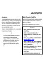
iERP: 127342
D5562/5 [English]
© BW Technologies 2008. All rights reserved.
Single Gas Detector
Quick Reference Guide
130258 GAXT QRG (D5562-6-EN).book Page 0 Monday, June 21, 2010 9:55 AM
Limited Warranty and Limitation Liability
BW Technologies LP (BW) warrants the product to be free from defects in material and workmanship under normal use and service for a period of
two years, beginning on the date of shipment to the buyer. This warranty extends only to the sale of new and unused products to the original buyer.
BW’s warranty obligation is limited, at BW’s option, to refund of the purchase price, repair or replacement of a defective product that is returned to
a BW authorized service center within the warranty period. In no event shall BW’s liability hereunder exceed the purchase price actually paid by the
buyer for the Product.
This warranty does not include:
a) fuses, disposable batteries or the routine replacement of parts due to the normal wear and tear of the product arising from use;
b) any product which in BW’s opinion, has been misused, altered, neglected or damaged, by accident or abnormal conditions of operation,
handling or use;
c) any damage or defects attributable to repair of the product by any person other than an authorized dealer, or the installation of unapproved
parts on the product; or
The obligations set forth in this warranty are conditional on:
a) proper storage, installation, calibration, use, maintenance and compliance with the product manual instructions and any other applicable
recommendations of BW;
b) the buyer promptly notifying BW of any defect and, if required, promptly making the product available for correction. No goods shall be
returned to BW until receipt by the buyer of shipping instructions from BW; and
c) the right of BW to require that the buyer provide proof of purchase such as the original invoice, bill of sale or packing slip to establish that the
product is within the warranty period.
THE BUYER AGREES THAT THIS WARRANTY IS THE BUYER ’S SOLE AND EXCLUSIVE REMEDY AND IS IN LIEU OF ALL OTHER WARRANTIES, EXPRESS OR IMPLIED,
INCLUDING BUT NOT LIMITED TO ANY IMPLIED WARRANTY OF MERCHANTABILITY OR FITNESS FOR A PARTICULAR PURPOSE. BW SHALL NOT BE LIABLE FOR ANY
SPECIAL, INDIRECT, INCIDENTAL, OR BASED ON CONTRACT, TORT OR RELIANCE OR ANY OTHER THEORY.
Since some countries or states do not allow limitation of the term of an implied warranty, or exclusion or limitation of incidental or consequential
damages, the limitations and exclusions of this warranty may not apply to every buyer. If any provision of this warranty is held invalid or
unenforceable by a court of competent jurisdiction, such holding will not affect the validity or enforceability of any other provision.
Contacting BW Technologies by Honeywell
USA: 1-888-749-8878
Europe: +44(0) 1295 700300
Canada: 1-800-663-4164
Other countries: +1-403-248-9226
Email us at: [email protected]
Visit BW Technologies by Honeywell’s website at: www.gasmonitors.com
GasAlert Extreme
Introduction
Safety Information - Read First
This quick reference guide provides basic information to operate the GasAlert Extreme gas detector. For complete operating
instructions, refer to the GasAlert Extreme User Manual provided on the CD-ROM. The GasAlert Extreme gas detector
(“the detector”) is designed to warn of hazardous gas levels
above user defined alarm setpoints.
Use the detector only as specified in this quick reference guide
and user manual, otherwise the protection provided by the
detector may be impaired.
The detector is a personal safety device. It is your responsibility
to respond properly to the alarm.
• Warning: Substitution of components may impair
Intrinsic Safety.
• Warning: To prevent ignition of flammable or
combustible atmospheres, disconnect power before
servicing.
• Warning: Use only the Panasonic CR-2PE/BN. Refer to
Replacing the Battery or Sensor.
• Warning: To reduce the risk of ignition of a flammable
atmosphere, batteries must only be changed in a safe
area free of hazardous gas.
• Calibrate only in a safe area that is free of hazardous
gas in an atmosphere of 20.9% oxygen.
• Use only a sensor specifically designed for the GasAlert
Extreme model.
• Do not deactivate the detector during a work shift.
Note
If you have a multi-language detector, the detector is
shipped with English as the default displayed
language. Additional languages provided are French,
German, Spanish, and Portuguese. The screens for
the additional languages are displayed on the
detector and in the corresponding quick reference
guide.
Read the following Cautions before using the detector.
a Cautions
1
GasAlert Extreme
Quick Reference Guide
•
•
•
•
•
2
Deactivating the detector resets the time-weighted
average (TWA), short-term exposure limit (STEL), and
maximum gas exposure values to 0.
If the detector is damaged or parts are missing, contact
BW Technologies by Honeywell immediately.
Do not use the detector if it is damaged. Before using
the detector, inspect the case. Look for cracks and
missing parts.
If the detector has been disassembled, ensure the front
and rear shells are properly aligned and fastened before
activating the detector. Refer to Maintenance.
BW recommends to bump test the sensor before each
day’s use to confirm its ability to respond to gas by
exposing the detector to a gas concentration that
exceeds the alarm setpoints. Manually verify that the
audible and visual alarms are activated. For detectors
with the calibration feature, calibrate the sensor if the
reading is not within the specified limits.
Calibrate the detector before first-time use, and then at
least once every 180 days. For HCN detectors, calibrate
once every 90 days.
• Ensure the sensor screen is not blocked.
• Do not cover the sensor grill with hands.
• Do not place the detector near the mouth or shoulders.
To avoid possible damage to the detector, adhere to the
following:
• Do not expose the detector to electrical shock and/or
severe continuous mechanical shock.
• The oxygen GasAlert Extreme detector is classified by
Underwriters Laboratories Inc. up to an atmosphere of
21% oxygen.
• Do not attempt to disassemble, adjust, or service the
detector unless instructions for that procedure are
contained in the user manual, and/or that part is listed
as a replacement part. Use only BW Technologies by
Honeywell replacement parts. Refer to Replacement
Parts and Accessories.
• The detector warranty will be voided if customer
personnel or third parties damage the detector during
repair attempts. Non-BW Technologies by Honeywell
repair/service attempts void this warranty.
GasAlert Extreme
Parts of the GasAlert Extreme
Parts of the GasAlert Extreme
Item
Description
1
Visual alarms bars (LEDs)
2
Liquid crystal display (LCD)
3
Pushbuttons
4
Audible alarm
5
Sensor and sensor grill
6
Infrared (IR) communication port
7
Alligator clip
3
GasAlert Extreme
Quick Reference Guide
Display Elements
Item
Note
Press and hold (until the backlight activates) any
button to activate the backlight for 6 seconds. When
the backlight option is enabled, the backlight
automatically activates for 3 seconds whenever there
is insufficient light to view the LCD. The detector is
shipped with the backlight option enabled.
The backlight does not activate when stealth mode is
enabled.
4
Description
1
Numeric value
2
Gas cylinder
3
Automatic span sensor
4
Passcode lock
5
Set alarm setpoints and user options
6
Maximum gas exposure
7
Alarm conditions
8
Battery
9
Data transmission
10
Alarm or alarm setpoint
11
Automatically zero sensor
12
Optional datalogger indicator
13
Parts per million (ppm)
14
Percentage by volume (% vol.)
15
Percentage by lower explosive limit (% LEL)
(future use)
GasAlert Extreme
Pushbuttons
Pushbuttons
Pushbutton
Description
• To activate the detector, press A.
A
• To deactivate the detector, press A and hold for 5 seconds.
• To enable/disable the confidence beep, while the detector is deactivated press and hold C. While
holding C, press A to enable or disable the confidence beep during startup.
• To decrement the displayed value or to scroll down, press E.
E
• To enter the user options menu, press E and D simultaneously and hold until OPTN and then EXIT
displays (5 seconds).
• To initiate calibration and define alarm setpoints, press E and C simultaneously until CAL. displays.
D
• To increment the displayed value or to scroll up, press D.
• To view the TWA, STEL, and maximum gas exposures, press D and C simultaneously.
• To save a displayed value, press C.
C
• To clear TWA, STEL, and maximum gas exposures, press and hold C for 6 seconds.
• To acknowledge a latched alarm, press C.
Activating the Detector
To activate the detector, press A. Once the detector passes the self-test, the detector enters normal operation.
Deactivating the Detector
To deactivate the detector, press A and hold for 5 seconds.A deactivation passcode can be enabled to ensure only authorized deactivations occur. This option can only be enabled at the factory and must be specified at time of order, and cannot be disabled by the
customer. Refer to the GasAlert Extreme User Manual.
5
GasAlert Extreme
Quick Reference Guide
Calibration
Procedure
Screen
Procedure
1. In a safe area free of hazardous gas and
in an atmosphere of 20.9% oxygen, press
E and C simultaneously and hold for 5
seconds. The detector beeps and vibrates
four times. After CAL. displays on the LCD,
the detector then beeps once more.
5. When the LCD flashes
, attach the
calibration cap and apply gas at a flow
rate of 500 to
1000 ml/min. The detector beeps three
times at the end of the span stage.
Remove the calibration cap and close the
valve on the gas cylinder.
2. The LCD flashes AUTO-ZERO while
the detector zeroes the sensor. The detector beeps twice at the end of auto-zero.
6. After a successful calibration, the LCD
displays CAL. DUE. Press E or D to
define the next calibration due date. Press
C to save.
Screen
7. Press C to bypass defining the alarm
setpoints.
3. If the detector is passcode protected,
PASS flashes on the LCD. The correct
passcode must be entered before defining
the calibration gas concentration.
4. The LCD displays the current calibration gas concentration. Press C to accept
the current concentration, or press E or
D to change the concentration and press
C to confirm the new concentration.
6
Or
Press E or D to change the alarm setpoint and press C to save the new value.
The detector beeps and vibrates four
times at the end of calibration.
a Warning
For correct flow and span rates, refer to the
GasAlert Extreme User Manual.
GasAlert Extreme
Attach the Gas Cylinder to the Detector
Attach the Gas Cylinder to the Detector
Item
Description
1
Calibration cap
2
Hose
3
Regulator
4
Gas cylinder
7
GasAlert Extreme
Quick Reference Guide
Alarms
Refer to the following table for information about alarms and corresponding screens. During an alarm condition, the detector activates the backlight and the LCD displays the current ambient gas reading.
Alarm
Screen
Alarm
Low Alarm
• Slow beep
TWA Alarm
• Slow beep
• Slow flash
• Slow flash
• ALARM flashes
• ALARM flashes
• Slow vibrations
• Slow vibrations
High Alarm
• Fast beep
STEL Alarm
• Fast beep
• Fast flash
• Fast flash
• ALARM flashes
• ALARM flashes
• Fast vibrations
• Fast vibrations
Sensor Alarm
• Slow beep
Low Battery Alarm
• Confidence beep disabled: One
beep and flash every 5 seconds and
one quick vibration every minute
Confidence beep enabled: Confidence beep deactivates. No beeps,
flashes, or vibrations.
• Slow flash
• ALARM flashes
• Slow vibrations
• LOW
8
displays
Screen
GasAlert Extreme
Alarms
Alarm
Screen
Alarm
Automatic Shutdown Alarm
(Low battery)
• Eight beeps, flashes, and vibrations
• LOW
displays
After Automatic Shutdown
(Low battery)
• No beep
Confidence Beep
• One beep every 5 seconds
• One quick vibration per minute
• No flash or vibrations
•
Screen
Automatic Shutdown Alarm
(Calibration past)
• Eight beeps, flashes, and vibrations
Note
displays for a short time
If the detector enters low
battery alarm, the confidence
beep deactivates.
Note
High alarm and STEL alarm have the same priority. A high alarm and/or STEL alarm overrides a low alarm and/or TWA
alarm. To check STEL and TWA alarms specifically, press and hold C and D simultaneously.
The vibrator alarm is disabled at -20°C.
The high and low alarms deactivate when the gas concentration is lower than the low alarm setpoint. If the alarms are set
to latch, alarms persist until the gas concentration is below the low alarm setpoint and the alarms have been acknowledged
by pressing C. The TWA and STEL alarms deactivate by clearing the TWA and STEL peak exposure. Refer to the
GasAlert Extreme User Manual to clear TWA and STEL peak exposures.
9
GasAlert Extreme
Quick Reference Guide
User Options Menu
Note
When selecting a user option, Set flashes and the
LCD displays the opposite of what is currently
enabled.
To access the user options menu, press and hold E and D
simultaneously until the LCD displays OPTN.
To scroll through the options, press E or D. Press C to select
the option. The following are the available user options:
• EXIT: Exits the user options menu.
• CLCK (Clock): Define the date and time of the detector.
• PASS (Passcode): Enable or disable passcode protection. Prevent unauthorized access to the user options
menu, calibration, and defining alarm setpoints.
• STLH (Stealth): Enable or disable stealth mode. This
option disables the audible alarms, LEDs, and backlight.
The vibrator alarm is disabled at -20°C.
• BKLT (Backlight): Enable or disable the automatic
backlight. When enabled, the backlight automatically
activates for 3 seconds whenever there is insufficient
light to view the LCD. When stealth mode is enabled,
this option is not available.
• LTCH (Latching alarms): Enable or disable the latching
alarm option. When enabled, the low and high gas
alarms (audible, visual, and vibrator) persist until the
gas concentration is below the low alarm setpoint and
the alarms have been acknowledged by pressing C.
10
• ACAL (Automatic oxygen calibration): Enable or disable
automatic oxygen calibration at startup. Only applicable
to the GasAlert Extreme oxygen detector.
• PAST (Calibration past due): Enable or disable automatic shutdown if calibration is past due (at startup).
• PORT, ESPA, DEUT, FRAN, or ENGL: The LCD can
display text in five different languages: Portuguese,
Spanish, German, French, or English. Only applicable to
detectors with the multi-language feature.
• RATE (Datalogger sampling rate option): Adjust the datalogger sampling rate. Only applicable to detectors with
the datalogger option.
• SEND (Data transfer): Transfers the datalogs and event
logs from the detector to the PC. Only applicable to
detectors with the datalogger option.
Information can be sent in the following three ways:
EVNT (Event): Sends all of the event logs.
LAST: Sends all of the datalogs since the last time they
were downloaded.
ALL: Sends all of the datalogs saved on the detector.
Note
Confidence Beep is not enabled in the user options
menu. To enable the confidence beep, while the
detector is deactivated press and hold C. While
holding C, press A. For more information refer to
the GasAlert Extreme User Manual.
GasAlert Extreme
Maintenance
Maintenance
To keep the detector in good operating condition, perform the
following basic maintenance as required:
• Calibrate, test, and inspect the detector at regular intervals.
• Keep an operations log of all maintenance, calibrations,
and alarm events.
• Clean the exterior with a soft damp cloth. Do not use
solvents, soaps, or polishes.
• Do not immerse the detector in liquids.
Replacing the Battery or Sensor
a Warning
To avoid possible personal injury, adhere to the following:
• Replace the battery in a safe area, free of hazardous gas
immediately when the detector enters low battery alarm.
• Use only the Panasonic CR-2PE/BN battery.
• Wear an ESD wrist or heel strap when replacing the
sensor or battery. Avoid touching electronic
components on the detector PCB or shorting circuits on
the PCB.
• Use only the sensor specifically designed for the
GasAlert Extreme. Otherwise, the detector will not
monitor the target gas. Refer to Replacement Parts and
Accessories in the GasAlert Extreme User Manual.
• After replacing a sensor, allow the new sensor 5 minutes
to stabilize before use. For an ETO or NO sensor, allow
the new sensor 2 hours to stabilize before use.
• Do not expose a sensor to vapors of organic solvents
such as paint fumes or organic solvents.
Note
When the battery is removed from the detector, the
clock reverts back to the default value. Refer to Clock
Option in the GasAlert Extreme User Manual.
To preserve the life of the battery, deactivate the detector when
not in use.
For additional information regarding problems caused by a sensor requiring calibration or replacement, refer to Troubleshooting in the GasAlert Extreme User Manual.
Replacing the Battery
To replace a battery, complete the following. Refer to Internal
Parts of the GasAlert Extreme and Internal Seals of the
GasAlert Extreme. Replace the battery in a safe area, free of
hazardous gas.
1.
Deactivate the detector.
2.
Remove the four machine screws on the rear shell
and remove the rear shell.
3.
Remove the battery.
ec Warning
This instrument contains a lithium battery. Do not mix with
the solid waste stream. Spent batteries should be disposed
of by a qualified recycler or hazardous materials handler.
11
GasAlert Extreme
Quick Reference Guide
4.
Insert the new battery.
5.
Re-assemble the detector. When assembling the
detector be aware of the following:
•
•
•
Clean the seal on the front and rear shells with a
soft damp clean cloth. Do not use solvents,
soaps, or polishes. Refer to Internal Seals of the
GasAlert Extreme.
Ensure the front and rear shells are properly
aligned to ensure a proper environmental seal.
Torque the screws to 3-4 in-lbs in a crisscross
pattern to ensure a proper environmental seal.
Do not overtighten.
Note
Allow the new sensor 5 minutes to stabilize before
use. For a new ETO or NO sensor, allow the new
sensor 2 hours to stabilize before use.
6.
•
•
•
Replacing the Sensor
To replace a sensor, complete the following. Refer to Internal
Parts of the GasAlert Extreme and Internal Seals of the
GasAlert Extreme.
12
1.
Deactivate the detector.
2.
Remove the four machine screws on the rear shell
and remove the rear shell.
3.
Remove the two machine screws from the PCB.
4.
Remove the PCB. Place the PCB on a clean, nonconductive surface.
5.
Replace the sensor.
Re-assemble the detector. When assembling the
detector, perform the following:
Clean the seal on the front and rear shells with a
soft damp clean cloth. Do not use solvents,
soaps, or polishes. Refer to Internal Seals of the
GasAlert Extreme.
Ensure the front and rear shells are properly
aligned to ensure a proper environmental seal.
Torque the screws to 3-4 in-lbs in a crisscross
pattern to ensure a proper environmental seal.
Do not overtighten.
Cleaning a Sensor Screen
Clean or replace the sensor screen as required. If replacement
sensor screens are required, refer to Replacement Parts and
Accessories in the GasAlert Extreme User Manual.
To clean a removed sensor screen, complete the following.
Refer to Internal Parts of the GasAlert Extreme and Internal
Seals of the GasAlert Extreme.
1.
Deactivate the detector.
2.
Remove the four machine screws on the rear shell
and remove the rear shell.
3.
Remove the two machine screws from the PCB.
GasAlert Extreme
Maintenance
4.
Remove the PCB. Place the PCB on a clean, nonconductive surface.
5.
Remove the screen.
6.
Using a soft, clean brush, wash the screen with clean,
warm water.
7.
Insert the sensor screen with the shiny side facing the
sensor grill.
Internal Seals of the GasAlert Extreme
Note
Ensure the screen is dry before reinserting into the
detector.
8.
Re-assemble the detector. When assembling the
detector be aware of the following:
•
•
•
•
When reinserting the sensor screen into the
detector, ensure the sensor screen is inserted
with the shiny side facing the sensor grill.
Clean the seal around the edge of the front and
rear shells with a soft damp clean cloth. Do not
use solvents, soaps, or polishes. Refer to Internal Seals of the GasAlert Extreme.
Ensure the front and rear shells are properly
aligned to guarantee a proper environmental
seal.
Torque the screws to 3-4 in-lbs in a crisscross
pattern to ensure a proper environmental seal.
Do not overtighten.
Item
Description
1
Seal
2
Front shell
3
Rear shell
13
GasAlert Extreme
Quick Reference Guide
Internal Parts of the GasAlert Extreme
Item
14
Description
1
Detector rear screws
2
Rear shell
3
Battery
4
Main PCB screws
5
Main PCB
6
Sensor
7
Sensor screen
8
Front shell
GasAlert Extreme
WEEE Directive and Battery Directive
WEEE Directive and Battery Directive
Specifications
Failure to comply with the following battery removal and disposal instructions may result in battery shorting, battery leakage, and/or other damage. Ensure a qualified technician
completes the following procedures.
Instrument dimensions: 2.8 x 5.0 x 9.5 cm
(1.1 x 2.0 x 3.75 in.)
Weight: 82 g (2.9 oz.)
Operating temperature:
H2S, SO2, HCN: -40°C to +50°C (-40°F to +122°F)
CO: -30°C to +50°C (-22°F to +122°F)
NH3 (high range): -20°C to +40°C (-4°F to +104°F)
Other gases: -20°C to +50°C (-4°F to +122°F)
Operating humidity:
CO, H2S, SO2, Cl2, HCN, NO2, NH3, PH3, ETO, NO, O3:
15% to 90% relative humidity (non-condensing)
Cl2: 10% to 95% relative humidity (non-condensing)
ClO2: 15% to 95% relative humidity (non-condensing)
O2: 0% to 99% relative humidity (non-condensing)
Removal and Disposal of the Battery
Only a qualified technician should complete the following procedure. Refer to Internal Parts of the GasAlert Extreme for parts of
the detector.
Dispose of the battery according to local laws.
1.
Press and hold C to deactivate the detector.
2.
Remove the four machine screws on the rear shell
and remove the rear shell.
3.
Remove the two machine screws from the PCB.
4.
Remove the PCB. Place the PCB on a clean, nonconductive surface.
5.
Remove the battery.
6.
Dispose of the battery according to local laws.
Alarm setpoints: All setpoints automatically display during the
start up self-test.
Detector ranges:
GasAlert Extreme O2: 0-30.0% vol (0.1% vol increments)
GasAlert Extreme CO: 0-1000 ppm (1 ppm increments)
GasAlert Extreme CO: (low H2): 0-1000 ppm (1 ppm increments)
GasAlert Extreme H2S: 0-100 ppm (1 ppm increments)
GasAlert Extreme H2S (high range): 0–500 ppm
(1 ppm increments)
GasAlert Extreme PH3: 0-5.0 ppm (0.1 ppm increments)
15
GasAlert Extreme
Quick Reference Guide
GasAlert Extreme SO2: 0-150.0 ppm (0.1 ppm increments)
GasAlert Extreme Cl2: 0-50.0 ppm (0.1 ppm increments)
GasAlert Extreme NH3: 0-100 ppm (1 ppm increments)
GasAlert Extreme NH3 (high range): 0-400 ppm
(1 ppm increments)
GasAlert Extreme NO2: 0-100.0 ppm (0.1 ppm increments)
GasAlert Extreme HCN: 0-30.0 ppm (0.1 ppm increments)
GasAlert Extreme ETO: 0-100.0 ppm (0.1 ppm increments)
GasAlert Extreme ClO2: 0-1.00 ppm (0.01 ppm increments)
GasAlert Extreme O3: 0-1.00 ppm (0.01 ppm increments)
GasAlert Extreme NO: 0-250 ppm (1 ppm increments)
Sensor type: Plug-in electrochemical cells
Calibration: Auto zero, set span, and span sensor
Oxygen sensor: Automatic span upon activation (enable/disable)
Alarm conditions: TWA alarm, STEL alarm, low alarm, high
alarm, sensor alarm, low battery alarm, confidence beep, and
automatic shutdown alarm.
Audible alarm: 95 dB at 1 ft. (0.3 m) typical
Visual alarm: Red light-emitting diode (LED)
Display: Alpha-numeric liquid crystal display (LCD)
Backlight: Automatically activates for 3 seconds whenever
there is insufficient light to view the LCD and during alarm conditions (unless the backlight is disabled in user options). Any
pushbutton reactivates the backlight for 6 seconds.
Self-test: Initiated at activation
16
User field options: automatic backlight, passcode protection,
latching alarm, calibration due lock, language selection, enable/
disable automatic oxygen calibration, datalog interval, data
transfer option, confidence beep, calibration interval, stealth
mode, set alarm setpoints, calibration span concentration
Year of manufacture: The detector’s year of manufacture is
determined from the serial number. The second and third number after the first letter determines the year of manufacture.
E.g. J410-H001000 = 2010 year of manufacture
Battery test: Every 0.5-second
Battery: 3 V lithium Panasonic CR-2PE/BN
Event logs: A maximum of 10 events are stored. When 10
events have been recorded, the next event overwrites the oldest event log.
Warranty: 2 years including sensors (1 year Cl2, NH3, O3,
ETO, and ClO2 sensor)
Intrinsic Safety:
Classified by UL to both U.S. and Canadian Standards as intrinsically safe for Class I, Division 1, Group A, B, C, D and Class
II, Group E, F, G
European Explosives Protection
CE 0539 g II 1G
Ex ia IIC T4 DEMKO 04 ATEX 0336363X
IECEx Ex ia IIC T4 Ga IECEx UL 08.0001X
ABS Type Approved: VA-348-169-X
GasAlert Extreme
Specifications
This equipment has been tested and found to comply with the
limits for a Class B digital device, pursuant to Part 15 of the
FCC Rules and ICES-003 Canadian EMI requirements. These
limits are designed to provide reasonable protection against
harmful interference in a residential installation. This equipment
generates, uses and can radiate radio frequency energy and, if
not installed and used in accordance with the instructions, may
cause harmful interference to radio communications. However,
there is no guarantee that interference will not occur in a particular installation. If this equipment does cause harmful interference to radio or television reception, which can be determined
by turning the equipment off and on, the user is encouraged to
try to correct the interference by one or more of the following
measures:
Reorient or relocate the receiving antenna.
Increase the separation between the equipment and receiver.
Connect the equipment into an outlet on a circuit different from
that to which the receiver is connected.
Consult the dealer or an experienced radio/TV technician for
help.
17
GasAlert Extreme
Quick Reference Guide
18
GasAlert Extreme
Specifications
19
GasAlert Extreme
Quick Reference Guide
20