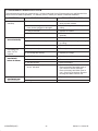
1
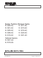
R
Builder Portfolio Whirlpool Baths:
K-1200-AC
K-1211-AC
K-1201-AC
K-1215-AC
K-1205-AC
K-1216-AC
K-1206-AC
K-1220-AC
K-1210-AC
K-1221-AC
Optional Aprons:
K-1507-AA
K-1515-AA
106548-CA (9437)
Copyright E1994 Kohler Co.
IMPORTANT SAFETY INSTRUCTIONS
ATTENTION INSTALLER: INSTRUCTIONS PERTAINING TO RISK OF FIRE, ELECTRIC
SHOCK OR INJURY TO PERSONS
READ AND FOLLOW ALL INSTRUCTIONS
WARNING: When using this unit, always follow basic precautions, including the following:
For -J1 and -JA models only: A green colored terminal
(or a wire connector marked “G”, “GR”, “GROUND”, or
“Grounding”) is provided within the terminal
compartment. To reduce the risk of electric shock,
connect this terminal or connector to the grounding
terminal of your electric service or supply panel with a
conductor equivalent in size to the circuit conductors
supplying this equipment.
DANGER: RISK OF ELECTRICAL SHOCK.
The installation must have a Class A
Ground-Fault Circuit-Interrupter (GFCI) for the
whirlpool system.
This will provide additional
line-to-ground shock hazard.
protection
against
Such a GFCI should be provided by the installer and
should be tested on a routine basis.
All models: A pressure wire connector is provided on
the exterior of the pump or control box within this unit to
permit connection of a No. 8 AWG (8.4 mm2) solid
copper bonding conductor between this unit and all other
electrical equipment and exposed metal in the vicinity, as
needed to comply with local requirements.
To test the GFCI, press the test button. The GFCI should
interrupt power. Press the reset button. Power should be
restored.
If the GFCI fails to operate in this manner, there is a
ground current flowing or the GFCI is defective. The
possibility of an electric shock may exist. DO NOT use
this unit. Disconnect the unit and have the problem
corrected by a qualified licensed electrician.
DO NOT operate this unit without the guard on the
suction fitting.
Use this unit only for its intended use as denoted in this
manual. DO NOT use attachments not recommended
by the Kohler Co.
Never drop or insert any object into any opening.
DANGER: To reduce the risk of injury, do not
permit children to use this unit unless they are
closely supervised at all times.
SAVE THESE INSTRUCTIONS
106548-CA (9437)
2
Kohler Co., Kohler WI
TABLE OF CONTENTS
IMPORTANT SAFETY INSTRUCTIONS . . . . . . . .
INTRODUCTION . . . . . . . . . . . . . . . . . . . . . . . . . . . . .
ROUGHING-IN: K-1200-AC, K-1201-AC . . . . . . . .
Ordering Information . . . . . . . . . . . . . . . . . . . . . . .
Required Electrical Service . . . . . . . . . . . . . . . . . .
Product Information . . . . . . . . . . . . . . . . . . . . . . . .
Installation Notes . . . . . . . . . . . . . . . . . . . . . . . . . .
ROUGHING-IN: K-1205-AC, K-1206-AC . . . . . . . .
Ordering Information . . . . . . . . . . . . . . . . . . . . . . .
Required Electrical Service . . . . . . . . . . . . . . . . . .
Product Information . . . . . . . . . . . . . . . . . . . . . . . .
Installation Notes . . . . . . . . . . . . . . . . . . . . . . . . . .
ROUGHING-IN: K-1210-AC, K-1211-AC . . . . . . .
Ordering Information . . . . . . . . . . . . . . . . . . . . . . .
Required Electrical Service . . . . . . . . . . . . . . . . . .
Product Information . . . . . . . . . . . . . . . . . . . . . . . .
Installation Notes . . . . . . . . . . . . . . . . . . . . . . . . . .
ROUGHING-IN: K-1215-AC, K-1216-AC . . . . . . . .
Ordering Information . . . . . . . . . . . . . . . . . . . . . . .
Required Electrical Service . . . . . . . . . . . . . . . . . .
Product Information . . . . . . . . . . . . . . . . . . . . . . . .
Installation Notes . . . . . . . . . . . . . . . . . . . . . . . . . .
ROUGHING-IN: K-1220-AC, K-1221-AC . . . . . . . .
Ordering Information . . . . . . . . . . . . . . . . . . . . . . .
Required Electrical Service . . . . . . . . . . . . . . . . . .
Product Information . . . . . . . . . . . . . . . . . . . . . . . .
Installation Notes . . . . . . . . . . . . . . . . . . . . . . . . . .
PRODUCT NOTICES . . . . . . . . . . . . . . . . . . . . . . . . .
Installer Hazard Notification . . . . . . . . . . . . . . . . .
Factory-Assembled Features . . . . . . . . . . . . . . . .
PRODUCT REQUIREMENTS . . . . . . . . . . . . . . . . .
Summary of Key Requirements . . . . . . . . . . . . . .
Plumbing Specifications . . . . . . . . . . . . . . . . . . . . .
Product Inspection . . . . . . . . . . . . . . . . . . . . . . . . .
Connections and Service Access . . . . . . . . . . . . .
Electrical Requirements . . . . . . . . . . . . . . . . . . . . .
INSTALLATION REQUIREMENTS . . . . . . . . . . . . .
Tools Required . . . . . . . . . . . . . . . . . . . . . . . . . . . . .
Materials Required . . . . . . . . . . . . . . . . . . . . . . . . .
Clearance Requirements . . . . . . . . . . . . . . . . . . . .
New Or Replacement Installation Requirements
Kohler Co., Kohler WI
2
4
5
5
5
5
5
6
6
6
6
5
7
7
7
7
7
8
8
8
8
8
9
9
9
9
9
10
10
10
11
11
11
11
11
11
12
12
12
12
12
SITE REQUIREMENTS . . . . . . . . . . . . . . . . . . . . . . .
Remove Old Bath . . . . . . . . . . . . . . . . . . . . . . . . . .
Subfloor Preparation . . . . . . . . . . . . . . . . . . . . . . . .
Stud Pocket Preparation . . . . . . . . . . . . . . . . . . . .
Plumbing Preparation . . . . . . . . . . . . . . . . . . . . . . .
BEFORE INSTALLING UNIT . . . . . . . . . . . . . . . . . .
Tiling-In Bead Installation . . . . . . . . . . . . . . . . . . . .
Partially Install Bath Drain . . . . . . . . . . . . . . . . . . .
Protect Bath Unit . . . . . . . . . . . . . . . . . . . . . . . . . . .
INSTALL WHIRLPOOL . . . . . . . . . . . . . . . . . . . . . . .
Whirlpool Set-In . . . . . . . . . . . . . . . . . . . . . . . . . . . .
Height Adjustment . . . . . . . . . . . . . . . . . . . . . . . . .
Secure Whirlpool . . . . . . . . . . . . . . . . . . . . . . . . . . .
Install Plumbing . . . . . . . . . . . . . . . . . . . . . . . . . . . .
ELECTRICAL CONNECTIONS AIR ACTUATOR VERSIONS . . . . . . . . . . . . . . . . . .
Identify Electrical Requirements . . . . . . . . . . . . . .
Wiring Information - 120 V, 60 Hz . . . . . . . . . . . .
Locate Field Wiring Compartment - 120 V, 60 Hz
Field Wiring Diagram - 120 V, 60 Hz . . . . . . . . . .
Field Wiring Control Box Compartment 230 V, 50 Hz . . . . . . . . . . . . . . . . . . . . . . . . . . . . . .
Connect Control Box - 230 V, 50 Hz . . . . . . . . . .
ELECTRICAL CONNECTIONS WALL TIMER VERSIONS . . . . . . . . . . . . . . . . . . . . .
Identify Electrical Requirements . . . . . . . . . . . . . .
Wiring Infromation - 120 V, 60 Hz Wall Timer Versions . . . . . . . . . . . . . . . . . . . . . . . .
WATER TEST WHIRLPOOL AND ELECTRONICS
COMPLETE FINISH WALL . . . . . . . . . . . . . . . . . . . .
OPTIONAL K-1507 APRON INSTALLATION . . . . .
OPTIONAL K-1515 APRON INSTALLATION . . . . .
COMPLETE INSTALLATION . . . . . . . . . . . . . . . . . .
CLEAN-UP AFTER INSTALLATION . . . . . . . . . . . .
CONFIRM PROPER OPERATION . . . . . . . . . . . . .
Start-Up Whirlpool . . . . . . . . . . . . . . . . . . . . . . . . .
Operating Sequence . . . . . . . . . . . . . . . . . . . . . . . .
Troubleshoot Whirlpool System . . . . . . . . . . . . . .
3
13
13
13
13
14
14
14
14
14
15
15
16
16
16
17
17
17
18
18
19
19
20
20
20
21
21
22
23
24
24
25
25
25
26
106548-CA (9437)
INTRODUCTION
Please read these instructions carefully to familiarize
yourself with the required tools, materials, and
installation sequences. Follow the sections that pertain
to your particular installation. This will aid you in avoiding
the unnecessary expense associated with improper
installation. In addition to proper installation, read all
operating and safety instructions.
All information in this manual is based on the latest
product information available at the time of publication.
Kohler Co. reserves the right to make changes in
product characteristics, packaging, or availability at any
time without notice.
The variety of installations possible with this whirlpool
may require framing procedures other than those
described in this manual.
Identify and record below the model and serial number (found at the pump end of the whirlpool):
Model No.
106548-CA (9437)
Serial No.
Date of Manufacture
4
Kohler Co., Kohler WI
1. ROUGHING-IN: K-1200-AC, K-1201-AC
A. ORDERING INFORMATION
C. PRODUCT INFORMATION
Factory installed components include pump and air switch
transmitter.
Information contained in this roughing-in also applies to
K-1201-J1-AA, K-1201-J1-AB and K-1201-JA-AA.
Whirlpool with wall timer
K-1200-AC
Whirlpool with air actuator (shown)
K-1201-AC
Fixture:
basin area
top area
weight
Bathing well
42” x 17”
55” x 25”
93 lbs.
water depth
capacity
12-1/8”
50 gals.
To overflow
Accessories/hardware:
Pump:
hp
V
Hz
A
60 Hz
1/2
120
60
8
Drain
K-7161-AF recommended
D. INSTALLATION NOTES
Vinyl tiling-in bead*
K-1177
Refer to installation instructions included with fixture before
beginning installation.
optional
*Use K-1177 vinyl bead when wall material contacts any
top surface of bath.
B. REQUIRED ELECTRICAL SERVICE
Dedicated circuits required, protected with Class A
Ground-Fault Circuit-Interrupter (GFCI):
Pump/control
120 V., 15 A, 60 Hz
ROUGHING-IN NOTES
Fixture dimensions are nominal and conform to tolerances in ANSI Standard Z124.1.
No change in measurements if connected with drain
illustrated.
Cut-out
28-1/2” x 58-1/2”
Minimum access:
Pump/control box 20” W x 15” H panel required
FIELD WIRING COMPARTMENT
15”
PUMP
1-1/2”
PUMP/CONTROL ACCESS
8-1/2”
30”
60”
2-3/4”
2-7/8”
3”
1.25>132
Kohler Co., Kohler WI
1-1/2”
3/16”
É
17”
1-1/2” I.P.S. THR’D
1-1/2” O.D.
5
106548-CA (9437)
2. ROUGHING-IN: K-1205-AC, K-1206-AC
A. ORDERING INFORMATION
C. PRODUCT INFORMATION
Factory installed components include pump and air switch
transmitter.
Information contained in this roughing-in also applies to
K-1206-J1-AA, K-1206-J1-AB and K-1206-JA-AA.
Fixture:
basin area
top area
weight
Bathing well
44” x 22”
55” x 25”
100 lbs.
water depth
capacity
15-1/8”
60 gals.
To overflow
Whirlpool with wall timer
K-1205-AC
Pump:
hp
V
Hz
A
Whirlpool with air actuator (shown)
K-1206-AC
60 Hz
1/2
120
60
8
Accessories/hardware:
Drain
K-7161-AF recommended
Vinyl tiling-in bead*
K-1177
D. INSTALLATION NOTES
Refer to installation instructions included with fixture before
beginning installation.
optional
*Use K-1177 vinyl bead when wall material contacts any
top surface of bath.
B. REQUIRED ELECTRICAL SERVICE
Dedicated circuits required, protected with Class A
Ground-Fault Circuit-Interrupter (GFCI):
Pump/control
120 V., 15 A, 60 Hz
ROUGHING-IN NOTES
Fixture dimensions are nominal and conform to tolerances in ANSI Standard Z124.1.
No change in measurements if connected with drain
illustrated.
Cut-out
FIELD WIRING COMPARTMENT
30-1/2” x 58-1/2”
Minimum access:
Pump/control box 20” W x 15” H panel required
16”
PUMP
1-3/8”
PUMP/CONTROL ACCESS
32”
1-1/2”
8-3/8”
60”
2-3/4”
2-7/8”
3”
1.25>132
106548-CA (9437)
3/8”
É
20”
1-1/2” I.P.S. THR’D
1-1/2” O.D.
6
Kohler Co., Kohler WI
3. ROUGHING-IN: K-1210-AC, K-1211-AC
A. ORDERING INFORMATION
C. PRODUCT INFORMATION
Factory installed components include pump and air switch
transmitter.
Information contained in this roughing-in also applies to
K-1211-J1-AA, K-1211-J1-AB and K-1211-JA-AA.
Fixture:
basin area
top area
weight
Bathing well
39” x 22”
54” x 27”
85 lbs.
water depth
capacity
15-1/2”
65 gals.
To overflow
Whirlpool with wall timer
K-1210-AC
Pump:
hp
V
Hz
A
Whirlpool with air actuator (shown)
K-1211-AC
60 Hz
1/2
120
60
8
Accessories/hardware:
Drain
K-7161-AF recommended
Vinyl tiling-in bead*
K-1179
D. INSTALLATION NOTES
Refer to installation instructions included with fixture before
beginning installation.
optional
*Use K-1179 vinyl bead when wall material contacts any
top surface of bath.
*Some K-1179 tiling-in beads may require trimming of the
bottom edge for proper fit.
B. REQUIRED ELECTRICAL SERVICE
Dedicated circuits required, protected with Class A
Ground-Fault Circuit-Interrupter (GFCI):
Pump/control
120 V., 15 A, 60 Hz
ROUGHING-IN NOTES
Fixture dimensions are nominal and conform to tolerances in ANSI Standard Z124.1.
No change in measurements if connected with drain
illustrated.
FIELD WIRING COMPARTMENT
Cut-out
34-1/2” x 58-1/2”
Minimum access:
18”
Pump/control box 20” W x 15” H panel required
PUMP
1-7/8”
8-7/8”
PUMP/CONTROL ACCESS
59-9/16”
1-3/4”
36”
3-1/4”
2-7/8”
3”
1.25>132
Kohler Co., Kohler WI
1-1/8”
É
21”
1-1/2” I.P.S. THR’D
1-1/2” O.D.
7
106548-CA (9437)
4. ROUGHING-IN: K-1215-AC, K-1216-AC
A. ORDERING INFORMATION
C. PRODUCT INFORMATION
Factory installed components include pump and air switch
transmitter.
Fixture:
basin area
top area
weight
Bathing well
52” x 23”
65-1/2” x
26-1/2”
95 lbs.
water depth
capacity
15-1/2”
76 gals.
Information contained in this roughing-in also applies to
K-1216-J1-AA and K-1216-JA-AA.
Whirlpool with wall timer
K-1215-AC
To overflow
Whirlpool with air actuator (shown)
K-1216-AC
Pump:
hp
V
Hz
A
60 Hz
3/4
120
60
10
Accessories/hardware:
Drain
K-7161-AF recommended
D. INSTALLATION NOTES
Vinyl tiling-in bead*
K-1179
Refer to installation instructions included with fixture before
beginning installation.
optional
*Use K-1179 vinyl bead when wall material contacts any
top surface of bath.
*Some K-1179 tiling-in beads may require trimming of the
bottom edge for proper fit.
B. REQUIRED ELECTRICAL SERVICE
Dedicated circuits required, protected with Class A
Ground-Fault Circuit-Interrupter (GFCI):
Pump/control
120 V., 15 A, 60 Hz
ROUGHING-IN NOTES
Fixture dimensions are nominal and conform to tolerances in ANSI Standard Z124.1.
No change in measurements if connected with drain
illustrated.
FIELD WIRING COMPARTMENT
Cut-out
34-1/2” x 70”
Minimum access:
Pump/control box 20” W x 15” H panel required
18”
PUMP
1-7/8”
8-7/8”
PUMP/CONTROL ACCESS
36”
1-3/4”
71-3/16”
3”
2-7/8”
3”
1.25>132
106548-CA (9437)
15/16”
É
21”
1-1/2” I.P.S. THR’D
1-1/2” O.D.
8
Kohler Co., Kohler WI
5. ROUGHING-IN: K-1220-AC, K-1221-AC
A. ORDERING INFORMATION
C. PRODUCT INFORMATION
Factory installed components include pump and air switch
transmitter.
Information contained in this roughing-in also applies to
K-1221-J1-AA and K-1221-JA-AA.
Fixture:
basin area
top area
weight
Bathing well
47” x 37”
67” x 32”
120 lbs.
water depth
capacity
16-7/8”
117 gals.
To overflow
Whirlpool with wall timer
K-1220-AC
Pump, 1 phase
hp
RPM
V
Hz
A
Whirlpool with air switch (shown)
K-1221-AC
60 Hz
3/4
3450
120
60
10
Accessories/hardware:
Drain
K-7161-AF recommended
Apron
K-1223
optional
Vinyl tiling-in bead*
K-1179
optional
D. INSTALLATION NOTES
Refer to installation instructions included with fixture before
beginning installation.
*Some K-1179 tiling-in beads may require trimming of the
bottom edge for proper fit.
*Use K-1179 vinyl bead when wall material contacts any
top surface of bath.
B. REQUIRED ELECTRICAL SERVICE
Dedicated circuits required, protected with Class A
Ground-Fault Circuit-Interrupter (GFCI):
Pump/control
120 V., 15 A, 60 Hz
ROUGHING-IN NOTES
Fixture dimensions are nominal and conform to tolerances in ANSI Standard Z124.1.
No change in measurements if connected with drain
illustrated.
Cut-out
24”
46-1/4” x 70-1/4”
Minimum access:
FIELD WIRING
COMPARTMENT
Pump/control box 20” W x 15” H panel required
PUMP
2”
PUMP/CONTROL ACCESS
9”
48”
72”
1-3/4”
3-1/2”
23”
2-7/8”
3”
Kohler Co., Kohler WI
13/16”
1-1/2” I.P.S. THR’D
1-1/2” O.D.
9
1.15>132
106548-CA (9437)
6. PRODUCT NOTICES
A. INSTALLER HAZARD NOTIFICATION
B. FACTORY-ASSEMBLED FEATURES
DANGER: Risk of fire, electric shock, or injury
to persons. Read important safety instructions on
inside front cover of these instructions.
K-1201, K-1206, K-1211, K-1216, K-1221: Factory
installed components include pump and air switch
transmitter. No installation is needed.
WARNING: Risk of electrical shock. A licensed
electrician should make all electrical connections.
K-1200, K-1205, K-1210, K-1215, K-1220: Factory
installed components include pump. Wall timer is
shipped attached to whirlpool harness.
WARNING: Risk of electrical shock. Connect
only to a circuit protected by a Ground-Fault
Circuit-Interrupter (GFCI).
WARNING: Risk
of
electrical
Disconnect power before servicing.
The whirlpool pump and piping are factory-assembled.
shock.
WARNING: Unauthorized modification may
cause unsafe operation and poor performance
of the whirlpool. Do not relocate the whirlpool
pump or make other modifications to the whirlpool
system, as this could adversely affect the
performance and safe operation of the whirlpool.
Kohler Co. shall not be liable under its warranty or
otherwise for personal injury or damage caused by
any such unauthorized modification.
WARNING: Risk of injury or property damage.
Please read all instructions thoroughly before
beginning installation, including the following
Product Requirements.
NOTICE: Follow all local plumbing and electrical
codes.
106548-CA (9437)
10
Kohler Co., Kohler WI
7. PRODUCT REQUIREMENTS
A. SUMMARY OF KEY REQUIREMENTS
B. PLUMBING SPECIFICATIONS
S Install unit to level subfloor.
If using a rim mounted bath faucet, flexible connections
between the valves and spout may be required. Confirm
adequate mounting and connection space of specified
faucet for your installation.
S Provide properly dimensioned framing.
S Bath can be installed in a corner. Recess, peninsular or sunken installation is also possible.
Confirm adequate support for faucet; large faucets that
may be inadvertently used as a means of support are not
appropriate or safe for this installation.
C. PRODUCT INSPECTION
D. CONNECTIONS AND SERVICE ACCESS
Carefully uncrate and inspect your product for damage.
Leave all materials in carton during construction to
prevent damage.
Before installation, ensure proper access to the final
connections.
NOTICE: Provide unrestricted service access to
the pump. An access panel 20” W x 15” H minimum
must be constructed to allow for sufficient clearance for
servicing the pump or controls. The access panel must
be located at the pump end of the whirlpool, through an
adjoining wall.
NOTICE: Make sure both connections to the
whirlpool pump are securely tightened.
The optional apron is removable to allow limited service
access.
E. ELECTRICAL REQUIREMENTS
K-1200-AC, K-1201-AC, K-1205-AC, K-1206-AC,
K-1210-AC, K-1211-AC, K-1215-AC, K-1216-AC,
K-1220-AC, K-1221-AC: The installation must have a
Class A Ground-Fault Circuit-Interrupter (GFCI). The
GFCI protects against line-to-ground shock hazard. Use
a 120 V, 15 A, 60 Hz separate service for the whirlpool.
Provide a separate equipment grounding conductor for
the inside grounding lug. Ground must not be connected
to any current-carrying conductor except at the main
service breaker box.
All 50 Hz models: The installation must have an Earth
Leakage Circuit Breaker (ELCB). This will provide
additional protection against line-to-ground shock
hazard. A 230 V, 50 Hz separate circuit that provides15
A of continuous service is required.
Kohler Co., Kohler WI
11
106548-CA (9437)
8. INSTALLATION REQUIREMENTS
A. TOOLS REQUIRED
B. MATERIALS REQUIRED
S Conventional woodworking tools
S Plumbers putty
S Arc pliers or 14” pipe wrench
S Water-resistant sealer
S Rule
S Wall coverings, as necessary
S Level
S RTV silicone sealant
S Safety shoes
S Four 1/4” x 1” lag screws
S Safety glasses
S Square
S Screwdriver
S Pliers
S Utility knife
C. CLEARANCE REQUIREMENTS
D. NEW OR REPLACEMENT INSTALLATION
REQUIREMENTS
Check roughing-in and room dimensions in order to
provide adequate available space for the bath unit.
This bath unit can be installed in new or existing
bathrooms.
For new installations: Position plumbing according to
roughing-in dimensions beginning on page 5. Cap
supplies and check for leaks.
For replacement installations: Remove old bath,
remove old wall material and remove old floor covering
from area. Remove old plumbing which does not
conform to roughing-in requirements.
106548-CA (9437)
12
Kohler Co., Kohler WI
9. SITE REQUIREMENTS
A. OLD BATH REMOVAL
Disconnect the drain at the trap. Remove old wall
material. Slip boards under old bath feet to protect
floor and slide old bath out of recess as illustrated.
Old Bath
Floor
Protection
Boards
B. SUBFLOOR PREPARATION
Check flooring under the bath and repair if necessary.
Make sure that the subfloor is level. Seal subfloor to
reduce the risk of water damage.
C. STUD POCKET PREPARATION
Construct a recess designed for your particular
installation. Framing is of 2 x 4 construction. Make sure
you allow for access to the pump or power panel in the
event the unit requires service. When constructing
framing allow for thickness of sub and finished wall
materials.
If an apron wall without a ledge is desired, the finished
apron wall surface must be 1/32” under the bath rim.
Bath can be installed in a corner. Recess, peninsular or
sunken installation is also possible. Possible studding
arrangements are illustrated in 1. through 2. below;
modifications may be needed for other types of
construction.
1.
Sunken Installation: For sunken installation,
refer to Roughing-In notes located in Roughing-In
section beginning on page 5 for cut-out detail. Make
sure the bath is supported by the supporting blocks
at the bottom of the bath.
Kohler Co., Kohler WI
13
106548-CA (9437)
2.
Recessed
Installation:
construction is illustrated.
Suggested
stud
D. PLUMBING PREPARATION
Position plumbing according to roughing-in dimensions.
Cap supplies and check for leaks.
10. BEFORE INSTALLING UNIT
A. TILING-IN BEAD INSTALLATION
Before setting bath, an optional tiling-in bead is
recommended to be applied to whatever side of the bath
contacts the wall. Refer to Ordering Information located
in Roughing-In section beginning on page 5. This bead
prevents water from seeping between the bath and the
wall. Install this bead now. Refer to Installation
Instructions packed with the tiling-in bead.
B. PARTIALLY INSTALL BATH DRAIN
Install drain on bath/whirlpool
manufacturer’s instructions.
according
to
C. PROTECT BATH UNIT
Place a drop cloth or similar material in bath/whirlpool
bottom. Be careful not to scratch product.
106548-CA (9437)
14
Kohler Co., Kohler WI
11. INSTALL WHIRLPOOL
A. WHIRLPOOL SET-IN
Choose one of the three recommended options below
that is best for your particular installation as described in
1., 2., or 3. Follow the appropriate instructions.
If subfloor is not level, some shimming of the bath and
pump will be necessary.
See 11.B. for height
adjustment.
1.
Sunken Installation: Set unit into sunken
installation. Make sure the bath/whirlpool is level
and is resting on all blocks. Insert the tailpiece into
the trap. Apply a bead of RTV sealant under rim of
the bath unit.
2.
Install Using Gypsum: Place a 2” thick layer of
gypsum cement (such as Gyp-Crete 2000) on the
floor where the whirlpool is to be set. This will help
secure, level and support the bath. Set bath into
position. Clear any excess cement from vicinity of
the pump.
NOTE: Pump bracket must sit flat on the floor.
Insert tailpiece into trap. Make sure bath is level
and resting on all supporting blocks.
3.
Whirlpool
Blocks
Install Using 1 x 2 Strips: Set whirlpool in desired
location and level. Nail 1 x 2 wood strips around
blocks under the whirlpool to firmly hold it in
position. It is not necessary to use strips on all
blocks. They are only needed on blocks that are to
the outside edges of your installation.
Insert tailpiece into trap. Make sure bath is level and
resting on all supporting blocks.
Wood
Strips
Wood
Strips
Kohler Co., Kohler WI
15
106548-CA (9437)
B. HEIGHT ADJUSTMENT
NOTICE: Steps B. and C. are necessary for making
your Kohler Whirlpool operate more quietly.
Drainage
If the subfloor is level, no adjustment is necessary;
proceed to Step C. If the subfloor is not level, shim
beneath pump bracket (plywood is recommended). Do
not change the elevation of the pump relative to the
whirlpool bath since this may affect performance. Use
a 5 x 7 (minimum) piece of plywood.
É
É
Shim if necessary, using 5” x 7”
(minimum) plywood
Bracket
C. SECURE WHIRLPOOL
Using four 1/4” x 1” lag screws, secure pump bracket to
subfloor. Predrilling is recommended.
Spacer
Plywood
(if required)
CAUTION: Risk of product damage. Do not
use the piping or pump for structural support or
positioning of whirlpools.
Use a 1/2” wrench to remove the long bolt securing the
bracket to the bath.
É
É
É
Bolt
Lag Screw
D. INSTALL PLUMBING
CAUTION: Risk of damage to whirlpool
bottom and subfloor. Ensure watertight seal on
bath drain connections.
1.
When whirlpool is securely positioned, connect
drain into trap. An access panel will simplify future
maintenance.
Connect Here
2.
Install the faucet valving and spout tee. If faucets
are deck-mounted, the deck must be finished
before handle trim and spout can be installed. Open
hot and cold valves and check all supply
connections for leaks.
3.
Run water in whirlpool and check drain connection
for leaks.
106548-CA (9437)
16
Kohler Co., Kohler WI
12. ELECTRICAL CONNECTIONS - AIR ACTUATOR VERSIONS
A. IDENTIFY ELECTRICAL REQUIREMENTS
The model number is printed on a plate at the pump end
of the module.
The model number identifies electrical rating. Electrical
connections for each model vary.
S K-1201-AC, K-1206-AC, K-1211-AC,
K-1216-AC, K-1221-AC:
(Follow Step B. below.)
60 Hz
S K-1201-J1-AA, K-1201-J1-AB, K-1206-J1-AA,
K-1206-J1-AB, K-1211-J1-AA, K-1211-J1-AB,
K-1216-J1-AA, K-1221-J1-AA:
60 Hz
(Follow Steps C. and D. below.)
S K-1201-JA-AA, K-1206-JA-AA, K-1211-JA-AA,
K-1216-JA-AA, K-1221-JA-AA:
50 Hz
(Follow Steps E. and F. below.)
See Electrical Requirements section on page 11 of
Product Requirements.
B. WIRING INFORMATION - 120 V, 60 HZ
(EXCLUDING -J1 MODELS)
WARNING: Risk of electrical shock. To reduce
the risk of electric shock, connect only to a properly
grounded, grounding-type receptacle, protected
by a Ground-Fault Circuit-Interrupter (GFCI). Do
not remove the plug’s grounding pin. Do not use a
grounding adapter.
Your Kohler Whirlpool bath is equipped with a cord and
plug. All wiring of the pump and control has been
completed at the factory. A licensed electrician must
install a GFCI protected, 120 Volt, 15 Amp, grounded
outlet. Your whirlpool may then be plugged into this
outlet. No other load should be on this circuit. Locate the
outlet within reach of the 36” cord.
Kohler Co., Kohler WI
17
106548-CA (9437)
C. LOCATE FIELD WIRING COMPARTMENT 120 V, 60 HZ (-J1 MODELS ONLY)
WARNING: Risk of electrical shock. Make sure
the power has been disconnected before
performing the following procedures. Refer to
Important Safety Instructions located on page 2.
CAUTION: Risk of electrical shock. All services
must
have
a
Class
A
Ground-Fault
Circuit-Interrupter (GFCI) which will provide
additional protection against line-to-ground shock
hazard.
Field Wiring
Compartment
Air
Actuator
Bonding
(Earthing)
Screw*
Air
Actuator
Tubing
A licensed electrician should make a routine service
connection to the field wiring compartment of the pump
containing black and white wires and ground screw.
NOTE: The electrician must supply a listed strain/relief
bushing in accordance with local codes.
Pump
Remove air actuator tubing from pump by gently pulling.
Next, remove the screw at the top of the pump near the
strain relief bushing. Save screw. Loosen screw at
bottom of pump. Remove pump cover to reveal field
wiring compartment.
* For bonding in accordance with National and Local
Codes.
Green (Ground)
D. FIELD WIRING DIAGRAM - 120 V, 60 HZ (-J1
MODELS ONLY)
White
(Neutral)
Black (Line)
The factory has prewired the whirlpool control system.
A 120 V, 15 A separate circuit is required. Provide a
separate equipment grounding conductor for the inside
grounding conductor for the inside grounding screw (14
AWG minimum). Ground must not be connected to any
current-carrying conductor except at the main service
breaker box (per National Electrical Code, Article
250-61-b).
To Electrician: Provide enough wire to
allow motor removal
upon servicing.
Strain Relief Bushing
(Not Provided)
Replace pump cover over field wiring compartment.
Fasten screw through cover at hole near strain relief at
top of pump. Tighten screw at bottom of pump. Snip off
approximately 1” of air actuator tubing and reattach to
pump. Make sure tubing is securely attached to pump.
Air Actuator Tubing
Connection
106548-CA (9437)
18
Kohler Co., Kohler WI
E. FIELD WIRING CONTROL BOX
COMPARTMENT - 230 V, 50 HZ
WARNING: Risk of electrical shock. Make sure
the power has been disconnected before
performing the following procedures. Refer to
Important Safety Instructions located on page 2.
CAUTION: Risk of electrical shock. All services
must have an Earth Leakage Circuit Breaker
(ELCB) which will provide additional protection
against line-to-ground shock hazard. A separate
service is required for the whirlpool.
The whirlpool controls and system have been prewired
at the factory. A licensed electrician should make a
routine service connection to the field wiring
compartment of the control box containing blue and
brown wires and earth lug.
Air
Actuator
Control
Box
Air
Actuator
Tube
Field Wiring
Compartment
Bonding
(Earthing) Lug*
Pump
* For bonding in accordance with National and Local
Codes.
F. CONNECT CONTROL BOX - 230 V, 50 HZ
Blue
(Neutral)
Neutral
Connect service to the field wiring compartment of the
control box. The 50 Hz model control box contains blue
and brown wires and earth lug.
A 230 V, 15 A, 50 Hz dedicated circuit is required.
Provide an Earth Leakage Circuit Breaker.
Phase (Line)
Provide a separate equipment earthing conductor for the
inside earth lug. The earthing conductor must not be
connected to any current carrying conductor. Follow
local electrical codes. A 230 V, 15A, 50 Hz separate
circuit is required.
Kohler Co., Kohler WI
Earth
(Ground) Lug
Earth
(Ground)
Brown
(Phase)
Wire Connectors
19
Earthing Lug (for
bonding in accordance with national
and local codes)
106548-CA (9437)
13. ELECTRICAL CONNECTIONS - WALL TIMER VERSIONS
A. IDENTIFY ELECTRICAL REQUIREMENTS
The model number is printed on a plate at the pump end
of the module.
The model number identifies electrical rating. Electrical
connections for each model vary.
S K-1200-AC, K-1205-AC, K-1210-AC,
K-1215-AC, K-1220-AC:
60 Hz
See Electrical Requirements section on page 11 of
Product Requirements.
B. WIRING INFORMATION - 120 V, 60 HZ –
WALL TIMER VERSIONS
DANGER: Risk of electrical shock. Do not
mount timer within reach of whirlpool user.
WARNING: Risk of electrical shock. To reduce
the risk of electric shock, connect only to a properly
grounded, grounding-type receptacle, protected
by a Ground-Fault Circuit-Interrupter (GFCI). Do
not remove the plug’s grounding pin. Do not use a
grounding adapter.
Your Kohler Whirlpool bath is equipped with a cord and
plug. All wiring of the pump and control has been
completed at the factory. A licensed electrician must
install a GFCI protected, 120 Volt, 15 Amp, grounded
outlet. Your whirlpool may then be plugged into this
outlet. No other load should be on this circuit. Locate the
outlet within reach of the 36” cord.
Black (Line)
White (Neutral)
G
F
C
I
Green (Ground)
TIMER
Black
Black
PUMP
White White
Green
Green
Install wiring from the GFCI to the wall timer location.
Use a switch box with adequate capacity.
106548-CA (9437)
20
Kohler Co., Kohler WI
14. WATER TEST WHIRLPOOL & ELECTRONICS
Check all electrical connections. Make sure both
connections to the pump are securely tightened.
Fill bath to a level at least 2” above the top of the highest
jet.
Operate whirlpool for 5 minutes and check all whirlpool
harness (piping) connections for leaks.
For additional information on whirlpool operation, see
Whirlpool Start-Up Instructions on page 25.
15. COMPLETE FINISH WALL
Gypsum Wallboard Subwall
CAUTION: Risk of product damage. Do not
support the weight of the whirlpool by the rim.
Finished Wall Material
Protect whirlpool surface. Make sure the vinyl bead is
attached securely to the sides being built into the wall.
Cover framing and walls with gypsum wallboard.
Water-Resistant Sealant
2 x 4 Studding
Tape and mud drywall...seal drywall and joints under
bath rim. Install finished wall material to subwall. Seal
joints between the whirlpool rim and finished wall using
silicone sealant.
Vinyl Tiling-In Bead
Bath Rim
Kohler Co., Kohler WI
21
106548-CA (9437)
16. OPTIONAL K-1507 APRON INSTALLATION
NOTE: For use with K-1205 and K-1206 models.
NOTICE: Before installing the optional K-1507
Apron: verify that both the finished floor and the bath
rim are level (and therefore parallel to each other). This
is necessary to ensure proper fit and appearance of the
apron. This apron should be installed after the finished
wall material is applied.
Flexible
1”
On one of the pieces of vinyl extrusion, use a hacksaw
and trim away or notch about 1” (25 mm) of the top end
rigid portion, leaving the flexible portion fully intact.
Repeat operation for the extrusion which will be installed
on opposite side of the apron. This procedure will
provide a better fit upon final installation.
Rigid
Install the vinyl extrusions on the right and left side of the
apron.
Vinyl Extrusion
Cut a 4’ length (approx.) of 2 x 2 batten board. Position
the board on the floor so that it will be centered between
the right and left sides of the apron, parallel with the bath
rim (apron side), and 3-3/4” (95 mm) inboard of the bath
rim outer edge (vertically-projected to the floor). Anchor
the 2 x 2 board to the floor.
Carpenter’s Square
Apron
Bath Rim
Extrusion
Remove the mating half of each velcro strip from the
bottom of the apron. Staple the velcro strips to the front
face of the 2 x 2 board.
Carefully insert the top lip of the apron into the extrusions
on the underside of the bath rim. Press the base of the
apron securely onto the velcro strips of the 2 x 2 board.
Velcro Strip
3-3/4”
2 x 2 Board
NOTE: The apron is removable to allow limited service access, if required.
106548-CA (9437)
22
Kohler Co., Kohler WI
17. OPTIONAL K-1515 APRON INSTALLATION
NOTE: For use with K-1200 and K-1201 models.
Make sure the bath is installed according to the
instructions. Provide backing on each of the recessed
walls for the nailing-in flange.
After bath is leveled and set, apply the vinyl trim strip to
the bath. Carefully apply a 1/16” bead of clear silicone
adhesive (provided) onto the vinyl strip as illustrated.
Apply vinyl strip to the underside of the bath rim, being
careful to align the lip of the strip to the bath rim as shown
in the inset. Immediately wipe off any excess sealant.
Silicone Adhesive
Vinyl Trim
Strip
Nailing-in
Flange
Apron
Tilt apron and carefully slip apron into groove on
underside of rim.
Temporarily tack a nail in the top hole of the nailing-in
flange on each side of the apron and ensure that the
apron is positioned as close to the bath rim as possible.
Vinyl Trim
Strip
Bath
Rim
Apron
Plumb the apron and secure the nailing-in flange using
#6d large-head galvanized nails.
Kohler Co., Kohler WI
23
106548-CA (9437)
18. COMPLETE INSTALLATION
INSTALL HANDLES AND SPOUT
After the deck is finished, attach the handles and spout
to complete faucet installation per manufacturer’s
instructions.
19. CLEAN-UP AFTER INSTALLATION
When cleaning up after installation, do not use
abrasive cleaners as they may scratch and dull the
module surface. Use warm water and one of the liquid
detergents to clean the surface.
106548-CA (9437)
Stubborn stains, paint, or tar can be removed with
turpentine or paint thinner. Do not allow cleaners
containing petroleum distillates to remain in
contact with whirlpool surfaces for long periods of
time. Plaster can be removed by scraping with a wood
edge. Do not use metal scrapers, wire brushes, or other
metal tools. One of the powder-type detergents may be
used on a damp cloth to provide mild abrasive action to
the residual plaster.
24
Kohler Co., Kohler WI
20. CONFIRM PROPER OPERATION
A. START-UP WHIRLPOOL
Refer to Important Safety Instructions on page 2
before operating this whirlpool.
Water Line
Please perform the following so that the owner may
safely receive the benefits of whirlpool bathing.
1.
Rotate jets so they are facing down toward basin.
2.
Fill the whirlpool bath to a water level at least 2”
above the top of the highest jet.
Bath
Wall
2” Minimum
Jet Trim
Water temperature in the whirlpool should not
exceed 104_F (40_C).
B. OPERATING SEQUENCE
TO
METHOD
OBSERVE
Refer to chart for proper operating sequence.
1.
Turn on the whirlpool jets. Adjust each jet for
optimum air/water mixture.
2.
A built-in timer automatically stops the motor after
20 minutes of operation.
Turn on whirlpool massage.
Add air to whirlpool action, rotate
flange counterclockwise. To
reduce air, turn
clockwise.
Reduce
Air
Add
Air
Shut off whirlpool.
Restart whirlpool
after 20 minute
cycle is complete.
Kohler Co., Kohler WI
25
106548-CA (9437)
C. TROUBLESHOOT WHIRLPOOL SYSTEM
This troubleshooting guide is for general aid only. A Kohler Authorized Service Representative or a qualified electrician
should correct all electrical problems. For warranty service, contact your dealer or wholesale distributor.
SYMPTOMS
1. Whirlpool does not
start/stop.
PROBABLE CAUSES
RECOMMENDED ACTION
A. No power to pump/power module.
A. Set/Reset GFCI/ELCB breaker; check
wiring to power module.
B. Air actuator tubing disconnected,
loose, kinked, plugged or damaged.
B. Connect, straighten, clean or replace
tubing.
C. Faulty air actuator.
C. Replace air actuator.
D. Faulty motor/pump assembly.
D. Rebuild or replace motor and pump
assembly.
A. Jet is closed.
A. Rotate jets counterclockwise to open.
B. Trim kit installed incorrectly.
B. Reinstall trim kit, checking for damage
to O-Ring.
C. Jets are blocked.
C. Remove blockage.
3. Motor turns, water
is pumping,
um ing, but
there is no air
injection.
A. No aspiration at jets.
A. Rotate jets counterclockwise.
B. Jet O-Rings are missing.
B. Replace jet O-Rings.
4. Whirlpool stops
automatically
before 18 minutes.
A. GFCI/ELCB trips.
A. Identify source of fault and correct.
B. Suction blocked.
B. Remove obstruction.
C. Jets are blocked.
C. Remove blockage.
D. Motor overheated and protection
device activated.
D. Check for blockage at motor vents.
Remove blockage and allow motor to
cool. Check for suction blockage.
Remove blockage and allow motor to
cool. Check for jet blockage. Remove
blockage and allow motor to cool.
A. Faulty timer mechanism.
A. Replace timer board.
B. Wiring error.
B. Refer to dealer.
2. Motor starts, all jets
are not functioning.
functioning
5. Whirlpool does not
automatically stop
after 22 minutes.
106548-CA (9437)
26
Kohler Co., Kohler WI
Kohler Co., Kohler WI
27
106548-CA (1093)
R
106548-CA (1093)
Kohler Co., Kohler WI