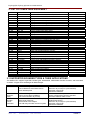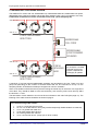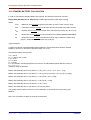
1
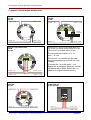
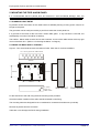
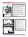
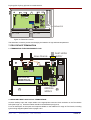
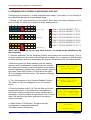
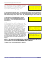
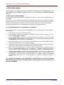
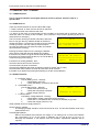
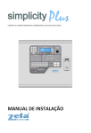
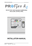
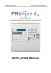
Simplicity 64 Simplicity 126 64 OR 126 DEVICE CAPACITY, SINGLE LOOP ANALOGUE ADDRESABLE FIRE ALARM CONTROL PANEL INSTALLATION MANUAL Simplicity 64 & Simplicity 126 INSTALLATION MANUAL. CONTENTS 1. SIMPLICITY OVERVIEW……………………………………………………………..…… 3 1.1 SETTING THE DEVICE ADDRESS (DETECTORS, CALL POINTS & SOUNDERS) 2. LIST OF COMPATIBLE EQUIPMENT………………………………………………..… 4 2.1 SUPPORTED SOUNDER TYPES & THEIR APPLICATIONS 3. INTRODUCTION…….…………………………………………………………………..… 3.1 3.2 3.3 3.4 3.5 4. FIRST FIX GUIDELINES…………………………………………………………………. 4.1 4.2 4.3 4.4 4.5 4.6 5. 6. 7. 8. 9. 10. 11. 12. 13. 14. 23 STANDBY BATTERY CALCULATION WIRING RECOMMENDATIONS……….. ……………….……………..……………… 25 PCB TERMINATION CONNECTIONS……….………………………………………… 26 14.1 14.2 15. 20 COMMON FAULT ZONE FAULTS SUPPLY FAULT EARTH FAULTS DOUBLE ADDRESS SYSTEM FAULT PRE-ALARM SOUNDER FAULTS LOOP WIRING FAULTS STANDBY BATTERY REQUIREMENTS ……………….……………..……………… 12.1 19 WHY USE TEST MODE TO PROGRAM ZONE IN TEST TO PROGRAM SOUNDER CIRCUITS IN TEST MODE GENERAL FAULT FINDING...………………………………………………………….. 11.1 11.2 11.3 11.4 11.5 11.6 11.7 11.8 11.9 18 WHY USE ZONE DISABLEMENT TO PROGRAM A ZONE (OR SOUNDERS) AS DISABLED TEST MODE………………………………………………………………………………. 10.1 10.2 10.3 14 ADDRESS - ZONE TABLE ZONE DISABLEMENT…………………………………………………………………… 9.1 9.2 13 TERMINATING THE DETECTION AND ALARM (SOUNDER) CIRCUITS AUXILIARY INPUT AND OUTPUT TERMINATIONS DESIGNING THE SYSTEM & CONFIGURING THE FACP…………………………. 8.1 LOOP CONTENTS FAULT FINDING 8.2 12 CONNECTING MAINS POWER CONNECTING THE BATTERIES FIELD DEVICE TERMINATION…..…………………………………………………….. 7.1 7.2 11 PLANNING CABLE ENTRY FIXING THE BACKBOX TO THE WALL CONNECTING MAINS & BATTERY POWER………………………………………… 6.1 6.2 6 RECOMMENDED CABLE TYPES AND THEIR LIMITATIONS MAINS WIRING RECOMMENDATIONS ADDRESSABLE LOOP WIRING DIAGRAM SPECIFIC DEVICE WIRING INSTRUCTIONS AUXILIARY INPUT WIRING EXAMPLES AUXILIARY OUTPUT WIRING (VOLTAGE FREE CHANGEOVER CONTACTS) MOUNTING THE FIRE ALARM PANEL………………………………………………. 5.1 5.2 5 THE PCBS USING THIS MANUAL ABOUT THE SIMPLICITY FACP & INTEGRAL PSE DESIGNING THE SYSTEM EQUIPMENT GUARANTEE CONNECTIONS FUSES CONTROL PANEL ELECTRICAL SPECIFICATIONS..…………………………….. 15.1 15.2 27 ENCLOSURE SPECIFICATIONS ELECTRICAL SPECIFICATIONS Approved Document No: GLT.MAN-107 Issue : 1.04 Authorised: GH Date: 05/10/2004 PAGE 2 Simplicity 64 & Simplicity 126 INSTALLATION MANUAL. 1.SIMPLICITY OVERVIEW The Simplicity is a 1-loop analogue addressable fire alarm control panel designed to EN54 part 2 & 4. It is available in two versions. Simplicity 64 allows 64 devices to be connected, and divided into 4 zones. Simplicity 126 allows 126 devices to be connected, and divided into 8 zones. They have been designed to give the advantages of an addressable system, with the “simplicity” of a conventional system. To help achieve this, the Simplicity uses its LEDs as the Primary source of information, so in most cases, there is no reason to look at the screen, or access any menus. The screen is simply there to identify loop device fault locations, and to help in setting up the panel. To simplify commissioning further, there is no zone allocation programming. Instead the loop is split into 8 zones (4 ON Simplicity 64), and each device is assigned to a zone by the address set with its 8 way dip switch. Address 1-16 Address 17-32 Address 33-48 Address 49-64 Address 65-80 Address 81-96 Address 97-112 Address 113-126 Zone 1 (Simplicity 64 & 126) Zone 2 (Simplicity 64 & 126) Zone 3 (Simplicity 64 & 126) Zone 4 (Simplicity 64 & 126) Zone 5 (Simplicity 126 only) Zone 6 (Simplicity 126 only) Zone 7 (Simplicity 126 only) Zone 8 (Simplicity 126 only) The Simplicity has been designed to only use addressable sounders (so that all devices sit on the same wiring loop). All sounders on a Simplicity panel will activate on any alarm. There are 2 types of sounder that the Simplicity panels can use; addressable or associated (sounder base). Addressable are generally more expensive, but can be started and stopped quickly by the panel. They have a maximum quantity of 32 per panel. Sounder Bases are generally less expensive, but have a start /stop time of up to 8 seconds. They have no maximum quantity, and are only limited by loop loading. 1.1 SETTING THE DEVICE ADDRESS (DETECTORS, CALL POINTS & SOUNDERS) The device address is set with a dip switch on the rear of the device. ON 1 2 3 4 5 6 7 8 The address setting is binary, with the ON position being binary 0 , and the OFF position being binary 1. Switch 8 is not used for setting the address, but sometimes has a device specific function. (check instructions that came with the device) If you are not familiar with binary, check the table on page 17, or use the following rule: Switch 7 off = add 64, Switch 6 off = add 32, Switch 5 off = add 16, Switch 4 off = add 8, Switch 3 off = add 4, Switch 2 off = add 2, Switch 1 off = add 1. The example shown would be: switches 6, 4 & 1 =32 + 8 + 1 = Address 41 LIMITATIONS OF PRESET ZONE ALLOCATION The main disadvantage of this method of zone allocation is the maximum zone capacity of 16 devices. If a zone has more than 16 devices it will need to be split into smaller zones. Similarly, a zone with only one device would leave 15 empty addresses on that zone. This will not cause a problem if it is considered at the system design stage. Approved Document No: GLT.MAN-107 Issue : 1.04 Authorised: GH Date: 05/10/2004 PAGE 3 Simplicity 64 & Simplicity 126 INSTALLATION MANUAL. 2. LIST OF COMPATIBLE EQUIPMENT Stock No 37-160 37-165 Product Code SP-64 SP-126 Device SIMPLICITY 64 device, 4 zone Fire Alarm Panel SIMPLICITY 126 device, 8 zone Fire Alarm Panel 80-110 80-120 80-130 80-131 80-140 80-150 80-050 80-080 80-090 80-100 80-101 43-001 43-022 48-100 48-105 48-110 48-115 42-007 42-008 42-030 48-020 47-055 47-056 47-110 42-001 42-002 42-004 42-005 42-011 42-013 41-003 41-005 FEAI2000 FEAO2000 FEAH2000 FEAHH2000 FEAOH2000 FECO2000 FE-CB FEA-RB FE-IB FEA-SB FEA-ISB ZT-MCP/AD ZT-MCP/AD/WP ZIU ZIOU ZSCC ZT-ZM ZAMT ZAMD ZAST ZTA/LE2 ZTA-FR50 ZTA-FR100 FE+50/AD ZMT/8 ZMD/8 ZST/8 ZIDC/10R ZFL2RR ZLT/8RR ZTB6B/24 ZTB8B Fyreye Addressable Ionisation Detector Fyreye Addressable Optical Detector Fyreye Addressable Heat Detector Fyreye Addressable High Temperature Heat Detector Fyreye Addressable Multi-Point Detector Fyreye Addressable Carbon Monoxide Detector Fyreye Common Base Fyreye Addressable Relay Base Fyreye Addressable Loop Isolator Base Fyreye Addressable Sounder Base Fyreye Addressable Isolator Sounder Base Zeta Addressable Call Point Zeta Weatherproof Addressable Call Point Zeta Input Unit Zeta Input Output Unit Zeta Sounder Control Module Zeta Zone Monitor Unit Zeta Addressable Maxitone Sounder Zeta Addressable Miditone Sounder Zeta Addressable Securetone Sounder Zeta Addressable Remote Led Indicator Fyreye Addressable Reflective Beam Detector 50m Fyreye Addressable Reflective Beam Detector 100m Fyreye Plus Addressable Aspiration Detector Zeta Conventional Maxitone Sounder Zeta Conventional Miditone Sounder Zeta Conventional Securetone Sounder Zeta Conventional Megatone Sounder Zeta Conventional Flasher Zeta Conventional Flasher Sounder Zeta Conventional 6” Bells Zeta Conventional 8” Bells 2.1 SUPPORTED SOUNDER TYPES & THEIR APPLICATIONS The SIMPLICITY supports 3 general sounder types; addressable, addressable sounder controller, and associated sounders. All types have advantages & disadvantages. Sounder type Addressable Advantage No Extra Cabling Can be fitted as a stand alone device Quick start/stop time Associated (sounderbase) Addressable Sounder Circuit Controller No Extra Cabling Doesn’t occupy Device Address Can have more than 32 per loop Allows conventional devices on Simplicity Wide range of devices Devices tend to be cheaper. Can add many sounder circuits to system Approved Document No: GLT.MAN-107 Issue : 1.04 Authorised: GH Date: 05/10/2004 Disadvantage Tends to be more expensive Maximum 32 per loop for quick start/stop Quiescent current high Uses device address. 4-8 second start & stop time. Always configured as common sounders. Must have detector fitted to work. Needs Extra Cabling. Needs External PSU Maximum 32 per loop for quick start/stop Quiescent current high Uses device address. PAGE 4 Simplicity 64 & Simplicity 126 INSTALLATION MANUAL. 3.INTRODUCTION THIS FIRE ALARM CONTROL PANEL IS CLASS 1 EQUIPMENT AND MUST BE EARTHED This equipment must be installed and maintained by a qualified and technically experienced person. 3.1 HANDLING THE PCBS If the PCBs are to be removed to ease fitting the enclosure and cables, care must be taken to avoid damage by static. The best method is to wear an earth strap, but touching any earth point (eg building plumbing) will help to discharge any static. Hold PCBs by their sides, avoiding contact with any components. Always handle PCBs by their sides and avoid touching the legs of any components. Keep the PCBs away from damp dirty areas, e.g. in a small cardboard box. 3.2 USING THIS MANUAL This manual explains, in a step-by-step manner, the procedure for the installation of the SIMPLICITY Range of Fire Alarm Control Panels. For full operational and maintenance information, please refer to document GLT.MAN-108 (USER MANUAL, MAINTENANCE GUIDE & LOG BOOK). It also contains a System set-up table, and Installation Certificate, that must be completed by the Commissioning Engineer prior to system handover. Unlike the User Manual, this Installation Manual must not be left accessible to the User. 3.3 ABOUT THE SIMPLICITY FIRE ALARM CONTROL PANEL & INTEGRAL PSE • The SIMPLICITY Fire alarm control panel is a one loop analogue addressable Fire Alarm Control Panel, with the loop split into 4 or 8 Zones. • It has a set of terminals to drive a 24V fire relayallows user to select appropriate relay for their application. • It has a set of terminals to drive a 24V fault relayallows user to select appropriate relay for their application. This output is normally powered to allow a fault signal in the case of total power failure. • It has a class change connection to allow remote activation of the sounders. (not required by EN54-2) • It has the ability to disable any zone or the addressable sounders. • It has a one man test mode, which resets the zone in test after 8 seconds.(EN54 option with requirements) • It has a maximum battery capacity of 7 Ah. • It will operate in ambient temperatures of –5 to o 40 C • It will operate in a relative humidity of up to 93% (non condensing) • It will withstand vibrations between 5 & 150 Hz • It has a maximum capacity of 32 devices per zone • The PSE is linear, with a 1.5A output at system voltage (18-32V) • The mains supply is filtered before entering the transformer. • The charger & battery are both fused at 1.6 (time delay) • The PSE will draw a maximum of 25uA from the battery in the event of mains failure. (the FACP will continue to take around 60mA) • The FACP & PSE should be maintained as described in section 3 of the User Manual, Maintenance Guide & Log Book. 3.4 DESIGNING THE SYSTEM This manual is not designed to teach Fire Alarm System design. It is assumed that the system has been designed by a competent person, and that the installer has an understanding of Fire Alarm System components and their use. We strongly recommend consultation with a suitably qualified, competent person regarding the design of the Fire Alarm System. The System must be commissioned and serviced in accordance with our instructions and the relevant National Standards. Contact the Fire Officer concerned with the property at an early stage in case he has any special requirements. If in doubt, read BS 5839: Pt 1: 2002 “Fire Detection and Alarm Systems for buildings (Code of Practice for System Design, Installation, commissioning and maintenance)” available from the BSI, or at your local reference library. 3.5 EQUIPMENT GUARANTEE If this equipment is not fitted and commissioned according to our guidelines, and the relevant National Standards, by an approved and competent person or organisation, the warrantee may become void. Approved Document No: GLT.MAN-107 Issue : 1.04 Authorised: GH Date: 05/10/2004 PAGE 5 Simplicity 64 & Simplicity 126 INSTALLATION MANUAL. 4. FIRST FIX All wiring must be installed to meet BS5839: Pt1: 2002 and BS 7671 (Wiring Regs) standards. Other National standards of fire alarm system installation should be adhered to where applicable. 4.1 RECOMMENDED CABLE TYPES AND THEIR LIMITATIONS Screened cables should be used throughout the installation to help shield the Panel from outside interference and ensure EMC compatibility. The two categories of cable according to BS5839: Pt1: 2002, Clause 26 “Fire Detection and Alarm Systems for Buildings (Code of Practice for System Design, Installation and Servicing)” are: Standard fire resisting cable – to PH30 classification of EN 50200 Enhanced fire resisting cable – to PH120 classification of EN 50200 (Note that all cables should be at least 1mm2 cross section On the Simplicity Panel the general recommendation would be to use standard fire resistant cable, such as Firetuff™ , FP200 or an equivalent. These cables are screened, and will provide good ECM shielding when properly grounded at the panel. Certain system specifications may demand the use of a particular type of cable and due regard should be paid to this fact. Depending on the environment, the cables may need mechanical protection (such as a conduit). 4.2 MAINS WIRING RECOMMENDATIONS The Mains supply to the FACP is fixed wiring, using Fire resisting 3-core cable (Between 1 mm² and 2.5mm²) or a suitable 3-conductor system, fed from an isolating double pole switch fused spur, fused at 3A. IT SHOULD NOT BE CONNECTED THROUGH AN RCD. This should be secure from unauthorised operation and be marked ‘FIRE ALARM: DO NOT SWITCH OFF’. The supply must be exclusive to the Fire Panel. MAKE SURE ANY SPARE ENTRY HOLES ARE COVERED WITH THE GROMMETS PROVIDED For information on how to connect Mains to the Panel’s Power Supply PCB, see page 8. Also refer to rating information on the mains cover inside the FACP. Approved Document No: GLT.MAN-107 Issue : 1.04 Authorised: GH Date: 05/10/2004 PAGE 6 Simplicity 64 & Simplicity 126 INSTALLATION MANUAL. 4.3 ADDRESSABLE LOOP WIRING DIAGRAM The SIMPLICITY comes with one addressable loop. Addressable detectors, addressable call points, addressable loop powered sounders and several other interface units can be connected to this loop. A maximum of 126 devices can be connected to each loop. (64 for Simplicity 64) Side A +ve -R -R L2 L2 EARTH EARTH EARTH UT L2 L1O -R L1 O L1 IN UT L1 UT L1O IN L1 IN Side A -ve FYREYE ADDRESSABLE DETECTORS - - + + -- + + ADDRESSABLE CALL POINT ADDRESSABLE LOOP POWERED SOUNDER Side B +ve -R L2 EARTH -IN+ +OUT -- EARTH L1 IN EARTH L1 O UT L1 IN UT L1O L1 IN Side B -ve L2 UT -R L2 L1O -R FYREYE ISOLATING BASE Note that some Devices (for example, a sounder controller circuit) may require a separate 24 volt supply to operate. FYREYE ADDRESSABLE DETECTORS A maximum of 32 loop-powered addressable sounders are permitted on the loop. There is no limit (loop load permitting) to the number of sounder bases that can be connected to a loop. On the Simplicity Panels, all Sounders are always configured as common sounders. Short circuit isolators should be used to prevent loosing the whole loop in the event of a single short circuit fault. They should be fitted to each zone boundary, such that any short circuit will only affect the devices in 1 zone. The termination of each detection circuit must be as indicated on the main PCB (See page 15). The Earthing of the cable screens should be as shown on page 9. Pre-Commissioning Cable Checks 1. 2. 3. 4. 5. 6. +ve in to +ve out less than 24 ohms -ve in to -ve out less than 24 ohms (may need to temporarily disable isolators to measure) +ve to –ve greater than 500k ohm +ve to Earth greater than 1M ohm. -ve to Earth greater than 1M ohm. +ve to –ve less than 50 mV pickup (on AC & DC scales) Approved Document No: GLT.MAN-107 Issue : 1.04 Authorised: GH Date: 05/10/2004 PAGE 7 Simplicity 64 & Simplicity 126 INSTALLATION MANUAL. 4.4 SPECIFIC DEVICE WIRING INSTRUCTIONS: Fyreye Common Base FE-CB 80-050 Fyreye Addressable Detector Relay Base FEA-RB 80-080 LOOP + IN LOOP + OUT LOOP + IN LOOP + OUT EARTH C -R -R LOOP - OUT LOOP - OUT Note that on the Fyreye Loop Isolator Base, the loop wiring connects to the terminal block on the PCB and NOT to the Base Spring Screws. Fyreye Loop Isolator Base FE-IB 80-090 The terminals are marked + & - in, and +,- &- out. EARTH The second –ve contact can be used during commissioning to check the loop integrity. L1 O -IN+ +OUT -- UT L1 IN -R L2 LOOP - IN RELAY OUTPUT L1 IN L1 IN LOOP - IN UT UT L1 O L1O L2 L2 EARTH LOOP - IN LOOP - OUT LOOP + IN LOOP + OUT Fyreye Addressable Sounder Base FEA-SB 80-100 LOOP + IN (Connect the –in to the spare – out. Repeat for all isolators. Measure –ve line resistance with a DVM. Return the –in cable to its original terminal block.) Zeta Glass Manual Call Point (Resetable) ZT-MCP/AD (/R) 43-001 (43-002) LOOP + OUT L2 EARTH L1O L1 IN -R UT LOOP - IN LOOP - OUT Approved Document No: GLT.MAN-107 Issue : 1.04 Authorised: GH Date: 05/10/2004 LOOP - IN LOOP - OUT LOOP + IN LOOP + OUT PAGE 8 Simplicity 64 & Simplicity 126 INSTALLATION MANUAL. Zeta Input Unit ZIU 48-100 Zeta Input Output Unit ZIOU 48-105 + + + + 47K EOL 0.5W N/C CM N/O 47K EOL 0.5W LOOP - IN LOOP - OUT LOOP + IN LOOP + OUT LOOP - OUT LOOP - IN LOOP + IN Zeta Sounder Controller Circuit ZSCC 48-110 LOOP + OUT Zeta Zone Monitoring Unit +1A PSU ZT-ZM 48-115 24 Volt Supply 24 Volt Supply + + + + 47K End of Line Resistor LOOP - IN LOOP + IN LOOP - OUT LOOP + OUT + - + + - 47K End of Line Resistor LOOP - IN LOOP + IN LOOP - OUT LOOP + OUT (Refer to device instructions for exact wiring information) Approved Document No: GLT.MAN-107 Issue : 1.04 Authorised: GH Date: 05/10/2004 PAGE 9 Simplicity 64 & Simplicity 126 INSTALLATION MANUAL. 4.5 AUXILIARY INPUT WIRING EXAMPLES There is one non-latching auxiliary input connection on the Fire Alarm Panel. Class Change Input (CC): This will energise all alarm outputs continuously when the CC terminals are shorted together. (This includes the addressable sounders, sounder bases. The auxiliary fire relay driver is NOT activated by the Class Change input.) Typical auxiliary input wiring options AUX FIRE RELAY CLASS CHANGE CLASS CHANGE CM NO 2nd Fire Alarm The termination for the above inputs must be as indicated on the main PCB (See page 15). The Earthing of the cable screens should be as shown on page 9. 4.6 AUXILIARY OUTPUT WIRING (24V Relay Drive Outputs) Auxiliary Fire Output (AUX): Supplies 24V in any fire condition. This is used to drive a 24 volt relay (coil voltage), which can be connected to emergency lights, local fire fighting equipment such as sprinkler systems, magnetic door holders, air conditioning shut off, etc. More than one relay can be connected to this output if required. Fault Output (FAULT): Gives 24V in the quiescent condition, and 0V in a fault condition. This ensures failsafe operation even in the event of total power loss. More than one relay can be connected to this output if required. Typical auxiliary output wiring RELAY OUTPUT NO CM NC FIT BACK-EMF DIODE ACROSS RELAY COIL FAULT Trigger I/P INDICATION DEVICE The fault relay is used to connect to a remote indication device RELAY FLT REP + RELAY OUTPUT NO CM NC FIT BACK-EMF DIODE ACROSS RELAY COIL RELAY Trigger I/P AUTODIALLER The fire relay can be used to connect to various devices which are activated on a fire alarm. Eg. Auto dialer , magnetic door release (24V), sprinkler system etc. + The termination for the above inputs must be as indicated on the main PCB (See page 15). The Earthing of the cable screens should be as shown on page 9. Approved Document No: GLT.MAN-107 Issue : 1.04 Authorised: GH Date: 05/10/2004 PAGE 10 Simplicity 64 & Simplicity 126 INSTALLATION MANUAL. 5. MOUNTING THE FIRE ALARM PANEL It is recommended that the panels door be removed to avoid accidental damage. Also, the termination PCB could be removed and stored in a safe place, while fixing the back box to the wall. 5.1 PLANNING CABLE ENTRY Fig.2 below shows the location of the cable entries to facilitate planning of wiring (home runs) to be brought to the panel. The grommets can be easily removed by a push from inside the control panel box. If a grommet is removed, fill the hole with a brass cable gland. If any knockout is removed, but subsequently not used, it should be covered up. The 230Va.c. Mains cable must be fed into the enclosure via one of the cable entries at the top right corner of the back box. (Refer to “Connecting the Mains” on Page 8). 5.2 FIXING THE BACK BOX TO THE WALL Figure 2: Plan view inside the enclosure without PCBs. Side view for surface installation. 12 x 19mm grommet cable entries 73mm 355mm 60 x 20mm back cable entry 60 x 20mm back cable entry 275mm 195mm 250mm 2 x 19mm knock-out cable entries Wall Mount Flush Mount Fix the enclosure to the wall using the three mounting holes provided. Check the build & condition of the wall to decide a suitable screw fixing. The mounting holes are designed for No 8 roundhead or countersunk woodscrews (or similar). Remove any debris from the enclosure. Take care not to damage the FACP during installation. Approved Document No: GLT.MAN-107 Issue : 1.04 Authorised: GH Date: 05/10/2004 PAGE 11 Simplicity 64 & Simplicity 126 INSTALLATION MANUAL. 6 CONNECTING MAINS & BATTERY POWER 6.1 CONNECTING THE MAINS POWER INLET MAINS SUPPLY The panel should be connected to 220-240V AC by a 3A rated spur to the fuse box with 1mm2 to 2.5mm2 3-core cable. Nothing else should be connected to this supply. IT SHOULD NOT BE CONNECTED TO AN RCD BREAKER. The Live, Earth and Neutral connections are marked on the PCB. The Mains is protected by a quick blow 20mm 2A HBC fuse. (Also known as HRC) The incoming mains cable should be kept separate from the loop cables to help minimise mains interference. Once the mains is connected, the protective cover should be replaced BEFORE turning on the mains power. This will minimise the chance of electric shock from the PCB. MAKE SURE ANY SPARE ENTRY HOLES ARE COVERED WITH THE PLASTIC GROMMETS PROVIDED It is advisable to apply power to the panel before connecting any devices, to check for correct operation, and to familiarise yourself with the fire alarm panels controls. INTERNAL WIRING Figure 3: Power Supply PCB layout and Mains connection details 6.2 CONNECTING THE BATTERIES Although there are many sizes of suitable battery, the sizes we usually recommend for the SIMPLICITY are 12V 7Ah, BATTERY INTERCONNECTING CABLE To calculate the exact requirement, use the equation in section 10, BATTERY CONNECTIONS TO PCB The two batteries are wired in series. CLAMP SEALED LEAD ACID BATTERY SEALED LEAD ACID BATTERY 12V / 7 Ah 12V / 7Ah The +ve of one battery is connected to the red battery lead. The –ve of the other battery is connected to the black battery lead. The –ve of the first battery is connected to the +ve of the second battery using the link wire supplied. When fitting the batteries, take care not to damage the temperature monitoring thermistors. See figure 4a overleaf. TO PCB BATTERY INTERCONNECTING CABLE 2 x 2Ah Batteries SEALED LEAD ACID BATTERY 12V / 2 Ah Figure 4: Battery location and connection details Approved Document No: GLT.MAN-107 Issue : 1.04 Authorised: GH Date: 05/10/2004 PAGE 12 Simplicity 64 & Simplicity 126 INSTALLATION MANUAL. LOOP WIRING A- A+ B- B+ 1 2 + CLASS CHANGE FLT REP + + + 13 3 4 5 6 MAINS FUSE 3A HBC CERAMIC 10 FS3 11 FS1 FS2 7 8 9 12 CONN29 LIVE NEUT- EARTH RAL THERMISTOR + SEALED LEAD ACID BATTERY SEALED LEAD ACID BATTERY 12V / 7 Ah 12V / 7Ah Figure 4a:Thermistor location The thermistor is used to prevent overcharging the batteries in high ambient temperatures. 7. FIELD DEVICE TERMINATION 7.1 TERMINATING THE ADDRESSABLE LOOP. INLET MAINS SUPPLY Brass Glands LOOP WIRING A- 10 1 A+ B- B+ + FLT REP + CLA SS CHANG E + + 13 2 3 4 5 6 MAINS FUSE 2A HBC CERAMIC FS3 11 CONN5 MAKE SURE ANY SPARE ENTRY HOLES ARE COVERED WITH THE GROMMETS PROVIDED FS1 FS2 7 8 9 12 CONN29 LIVE NEUT- EARTH RAL + LIVE NEUT- EARTH RAL INTERNAL WIRING Figure 6: Addressable Loop Connection 7.2 AUXILIARY INPUT AND OUTPUT TERMINATIONS Connect auxiliary input and output cables to the appropriate connector block terminals on the Termination PCB (See Page 15). Screened cables should be terminated as per figure 6. For a full description of the inputs and outputs available on the SIMPLICITY range of Fire Panels, including typical wiring diagrams please refer to pages 5 & 6. Approved Document No: GLT.MAN-107 Issue : 1.04 Authorised: GH Date: 05/10/2004 PAGE 13 Simplicity 64 & Simplicity 126 INSTALLATION MANUAL. 8. DESIGNING THE SYSTEM & CONFIGURING THE FACP Configuring the Simplicity is a fairly straightforward matter. It just takes a bit of thought to zone allocation during the system design stage. 1. Decide on the zone allocation for the system. Each zone can have a maximum of 16 devices fitted. Consider the simplified 3-storey building below. SECOND FLOOR ZONE 1: DEVICE ADDRESS 1 TO 16 ZONE 2: DEVICE ADDRESS 17 TO 32 ZONE 3: DEVICE ADDRESS 33 TO 48 FIRST FLOOR ZONE 4: DEVICE ADDRESS 49 TO 64 ZONE 5: DEVICE ADDRESS 65 TO 80 ZONE 6: DEVICE ADDRESS 81 TO 96 ZONE 7: DEVICE ADDRESS 97 TO 112 GROUND FLOOR (Note that a Simplicity 64 can only have 4 zones, so would not be suitable for the above system) 2. Sounder operation. On the Simplicity Panels, all sounders are common acting. That is, an alarm signal from any device will activate all sounders. If you require any kind of zonal sounder operation, ask your dealer about the premier AD & Premier AL Fire Alarm Panels. 3 After the system has been installed, and the cabling Fire Alarm Panel checked and the addresses of each device set, connect To EN54 pt2 & pt4 the loops to the fire alarm panel and power up the system System Normal (mains & batteries). It should say “system normal, and only B the green Power LED will be lit. There will be the letter “B” in the bottom left hand corner. This stands for Benign, or controls OFF. Fire Alarm Panel To EN54 pt2 & pt4 4. Turn the keyswitch to the Controls Enabled Position. System Normal The Letter “B” will now change to an “A”, for controls A Active. 5. Enter the access code 3 6 9. This will take you to the configuration menu. In this Menu there are options to view loop contents, configure the panel, edit the device message, or view the status of each device. The Covered option will exit from the menu, and return the panel to normal operation. 6. Select Option 3 (Configure). The panel will say Configuration in progress please wait. This takes around 20 seconds. Approved Document No: GLT.MAN-107 Issue : 1.04 Authorised: GH Date: 05/10/2004 Configuration Menu 1:Lp1 Dev 4:Messages 2:------- 5:Dev Stat 3:Config 6:Covered Configuration in Progress Please Wait PAGE 14 Simplicity 64 & Simplicity 126 INSTALLATION MANUAL. 7. To check that the panel has read all the devices on loop 1, select option 1 Lp1 Dev. If the loop contents are as expected, go to point 8, otherwise go to Loop Contents Fault Finding on page 16. CO I/O ZMU HET 00SCC 01ION 00OPT 03BGU 14Loop 1 00DAD 00 45Cancel 05= Exit 8. Press cancel to leave the menu. The panel is now configured, and will function as a basic system, (press 6 for covered), but it is more useful to enter device labels, to give a more precise location of an alarm device. We recommend that the device labels be entered to allow the panel to be more user friendly during normal operation. 9. Select option 4 for message editing. The panel will now ask for its write enable switch to be set to the on position . (This is the dip switch on the CPU board, switch 1). Please Set The Write Enable Switch To the On Position 10. The panel will now ask for the loop number, and the loop address of device name to be entered. Press enter to confirm loop 1, and enter again to confirm address 001. Enter the device label using the built in Message Editing keyboard. The label can be 20 characters long, Loop:1 Address:001 so try to be as descriptive as possible. Use the caps Floor 1. Bedroom 20 lock for capital letters. The delete button is used to Can: Exit Ent: Next correct mistakes. When the label has been entered, record the device type & label in the system setup chart in the user manual. Press enter 3 times to move to the next device (or enter the loop number and address to move forward several places. Please Set The 12 When all devices have been entered, press Cancel Write Enable Switch to exit the message editing screen. The panel will ask To the Off Position for the write enable switch to be set back to the off position . NOTE: IF THE PANEL IS POWERED DOWN WITH THE WRITE ENABLE SWITCH ON, IT WILL ERASE THE DEVICE LABELS WHEN IT IS RE-POWERED. The panel is now configured and ready for operation. Approved Document No: GLT.MAN-107 Issue : 1.04 Authorised: GH Date: 05/10/2004 PAGE 15 Simplicity 64 & Simplicity 126 INSTALLATION MANUAL. 8.1 LOOP CONTENTS FAULT FINDING If the loop contents are different to what was expected, then there may be some wrong connections to devices (they are polarity sensitive), or double addresses on the loop. (A double address is when 2 or more devices have been set to the same address, so they both answer at the same time.) Device Type: HEAT * Value:26 No Devs:1 ==================== Loop:1 Address:001 Return to the configuration menu & select option 5 (Dev status). Wait for the panel to read loop 1 address 001. The panel will give the device type & its analogue value. If the device is configured, there will be an asterix (*) next to the device type. Number of devices should read 1 (a reading of 2 or more will mean a double address is present). Press next to move to the next address on the loop. (The Previous button cannot be used in this menu. It can only be used to scroll between multiple faults or alarms.) Read all devices on the loop and compare with what was expected. If one address has 2 devices, and another is “missing”, the missing device could have a wrong address setting. If many devices are missing, check that they have power. There may be more than one break in the cable (the panel reads all devices when it has a single break, and will report a loop fault after a minute or so). 8.2 ADDRESS - ZONE TABLE On the SIMPLICITY, each available address corresponds to a zone, with 1-16 being in zone 1, 17-32 being in zone 2, 33-48 in zone 3 etc. The table below shows the dip switch settings for each address, and the zone that address will be in. Eg to set address 37, find 37 in the table. It is at sw 7,6,5 = 010, and sw 4,3,2,1= 0101 Remembering that 0 = ON & 1 = OFF, the switch settings for 37 are: 7=ON, 6=OFF, 5=ON, then 4=ON, 3=OFF, 2=ON, 1=OFF SW 4,3,2,1 LOOP 1 LOOP 2 OOO OOOO OOO1 OO1O OO11 O1OO O1O1 O11O O111 1OOO 1OO1 1O1O 1O11 11OO 11O1 111O 1111 N/A 1 2 3 4 5 6 7 8 9 10 11 12 13 14 15 ZONE 1 ZONE 9 7,6,5 OO1 16 17 18 19 20 21 22 23 24 25 26 27 28 29 30 31 ZONE 2 ZONE 10 O1O 32 33 34 35 36 37 38 39 40 41 42 43 44 45 46 47 ZONE 3 ZONE 11 SW O11 48 49 50 51 52 53 54 55 56 57 58 59 60 61 62 63 ZONE 4 ZONE 12 1OO 64 65 66 67 68 69 70 71 72 73 74 75 76 77 78 79 ZONE 5 ZONE 13 1O1 80 81 82 83 84 85 86 87 88 89 90 91 92 93 94 95 ZONE 6 ZONE 14 11O 96 97 98 99 100 101 102 103 104 105 106 107 108 109 110 111 ZONE 7 ZONE 15 111 112 113 114 115 116 117 118 119 120 121 122 123 124 125 126 N/A ZONE 8 ZONE 16 (NOTE: Only 4 zones are available on the Simplicity 64) As an alternative to using this chart, use the table on the following page:Approved Document No: GLT.MAN-107 Issue : 1.04 Authorised: GH Date: 05/10/2004 PAGE 16 Simplicity 64 & Simplicity 126 INSTALLATION MANUAL. ADDRESS 0= 1= 2= 3= 4= 5= 6= 7= 8= 9= 10 = 11 = 12 = 13 = 14 = 15 = 16 = 17 = 18 = 19 = 20 = 21 = 22 = 23 = 24 = 25 = 26 = 27 = 28 = 29 = 30 = 31 = SWITCHES 1 2 3 4 5 6 7 n o t u s e d off on on on on on on on off on on on on on off off on on on on on on on off on on on on off on off on on on on on off off on on on on off off off on on on on on on on off on on on off on on off on on on on off on off on on on off off on off on on on on on off off on on on off on off off on on on on off off off on on on off off off off on on on on on on on off on on off on on on off on on on off on on off on on off off on on off on on on on off on off on on off on off on off on on on off off on off on on off off off on off on on on on on off off on on off on on off off on on on off on off off on on off off on off off on on on on off off off on on off on off off off on on on off off off off on on off off off off off on on ADDRESS 32 = 33 = 34 = 35 = 36 = 37 = 38 = 39 = 40 = 41 = 42 = 43 = 44 = 45 = 46 = 47 = 48 = 49 = 50 = 51 = 52 = 53 = 54 = 55 = 56 = 57 = 58 = 59 = 60 = 61 = 62 = 63 = Approved Document No: GLT.MAN-107 Issue : 1.04 Authorised: GH Date: 05/10/2004 SWITCHES 1 2 3 4 5 6 7 on on on on on off on off on on on on off on on off on on on off on off off on on on off on on on off on on off on off on off on on off on on off off on on off on off off off on on off on on on on off on off on off on on off on off on on off on off on off on off off on off on off on on on off off on off on off on off off on off on on off off off on off on off off off off on off on on on on on off off on off on on on off off on on off on on off off on off off on on off off on on on off on off off on off on off on off off on on off off on off off on off off off on off off on on on on off off off on off on on off off off on on off on off off off on off off on off off off on on on off off off off on off on off off off off on on off off off off off on off off off off off off on ADDRESS 64 = 65 = 66 = 67 = 68 = 69 = 70 = 71 = 72 = 73 = 74 = 75 = 76 = 77 = 78 = 79 = 80 = 81 = 82 = 83 = 84 = 85 = 86 = 87 = 88 = 89 = 90 = 91 = 92 = 93 = 94 = 95 = SWITCHES 1 2 3 4 5 6 7 on on on on on on off off on on on on on off on off on on on on off off off on on on on off on on off on on on off off on off on on on off on off off on on on off off off off on on on off on on on off on on off off on on off on on off on off on off on on off off off on off on on off on on off off on on off off on off off on on off on off off off on on off off off off off on on off on on on on off on off off on on on off on off on off on on off on off off off on on off on off on on off on off on off off on off on off on off on off off on off on off off off off on off on off on on on off off on off off on on off off on off on off on off off on off off off on off off on off on on off off off on off off on off off off on off on off off off off on off off off off off off on off PAGE 17 ADDRESS 96 = 97 = 98 = 99 = 100 = 101 = 102 = 103 = 104 = 105 = 106 = 107 = 108 = 109 = 110 = 111 = 112 = 113 = 114 = 115 = 116 = 117 = 118 = 119 = 120 = 121 = 122 = 123 = 124 = 125 = 126 = 127 = SWITCHES 1 2 3 4 5 6 7 on on on on on off off off on on on on off off on off on on on off off off off on on on off off on on off on on off off off on off on on off off on off off on on off off off off off on on off off on on on off on off off off on on off on off off on off on off on off off off off on off on off off on on off off on off off off on off off on off off on off off off on off off off off off off on off off on on on on off off off off on on on off off off on off on on off off off off off on on off off off on on off on off off off off on off on off off off on off off on off off off off off off on off off off on on on off off off off off on on off off off off on off on off off off off off off on off off off off on on off off off off off off on off off off off off on off off off off off off n o t u s e d Simplicity 64 & Simplicity 126 INSTALLATION MANUAL. 9. ZONE DISABLEMENT The Simplicity fire alarm panels are designed to operate as zone based panels. You can therefore only disable a whole zone. It is not possible to disable individual devices. 9.1 WHY USE ZONE DISABLEMENT To aid commissioning and assist routine maintenance checks, any of the zones or loop sounders can be disabled. When a zone (or Loop sounders) are disabled, the panel will not respond to any fault or fire signals it receives from that zone*. This might be used if the system requires routine maintenance, and the customer needs the system to continue running, but doesn’t want spurious faults or false alarms. The panel will respond in the usual manner to any events in any non-disabled zones. 9.2 TO PROGRAMME ZONE (OR SOUNDERS) AS DISABLED Any number of zones (or the sounders) can be disabled, but it is good practice to only disable one zone at a time. 1. Insert and turn control key to enabled position; 2. Press DISABLE button and the ZONE 1 DISABLED LED will flash (The panel is now in SELECT DISABLEMENT MODE) 3. Press DISABLEMENT SELECT until the required zone or sounder circuit is lit. Press DISABLEMENT CONFIRM button, and the LED will come on steady, along with the GENERAL DISABLEMENT LED This section is now disabled*. 4. If more than one zone (or sounder) needs to be disabled, then press DISABLEMENT SELECT again until the required zone (or sounder) is selected. 5. If the panel needs to be taken out of SELECT DISABLEMENT MODE (eg to silence a fault on another part of the system), turn the keyswitch off, then back on again. 6. Once all the work has been done the zones need to be enabled again. If the panel is still in SELECT DISABLEMENT MODE, jump to paragraph 7, otherwise, turn the keyswitch to controls enabled, press DISABLE button. The panel is now in SELECT DISABLEMENT MODE 7. Press the DISABLEMENT SELECT button until the disabled zone has been selected. Press DISABLEMENT CONFIRM button to de-select disablement. Scroll to any other disabled zone and enable in the same way. When all zones are enabled again, the GENERAL DISABLEMENT LED will turn off. Turn the keyswitch to off position to return the system to normal. *To enable the system to be functional in the event of a real fire during maintenance, the manual call points remain active, even if the zone they are in has been disabled Approved Document No: GLT.MAN-107 Issue : 1.04 Authorised: GH Date: 05/10/2004 PAGE 18 Simplicity 64 & Simplicity 126 INSTALLATION MANUAL. 10. TEST MODE 10.1 WHY USE TEST MODE To aid commissioning and assist routine maintenance check, a non-latching ‘one man test’ facility is available. When a detector or manual call point is triggered on any zone in Test, the Alarm sounders operate for approximately eight seconds on and four seconds off. This cycle continues until the cause of the Alarm is removed (either by the test smoke clearing from the detector or the manual call point being reset), sounders will then stop activating. Should an Alarm occur on a zone that is not programmed to test, the Fire Alarm Panel will cancel the test mode. After the cause of the alarm has been checked, and the panel reset, test mode will have to be selected again to resume testing. 10.2 TO PROGRAMME ZONE IN TEST MODE NOTE: Only one zone can be programmed in test at any one time. 1. Insert and turn control key to enabled position; 2. Press TEST Button, followed by the code 2 4 8. 3. The GENERAL TEST LED will light steady, and Zone 1 test led will flash. 4. Press TEST FUNCTION SELECT button to select the zone to be tested. 5. Press confirm to enter test mode for this function. The LED will now be steady. 6. Once testing of that zone is completed, press TEST FUNCTION SELECT button to move to another Zone or turn the control key switch to off position to exit test mode. NOTE: If testing a call point, it will trigger the panel into alarm immediately, but it will need to stay active for around 8 seconds before the panel registers it as a test mode alarm. If the call point is active for less than 8 seconds, the sounders WILL NOT RESET. 8.3 TO PROGRAM SOUNDER CIRCUITS IN TEST MODE NOTE: Only the ADDRESSABLE SOUNDERS can be tested with the one man test mode. The ASSOCIATED SOUNDER BASES cannot be tested this way because of their slow stop/start time. 1. Insert and turn control key to enabled position; 2. Press TEST Button, followed by the code 2 4 8. 3. Zone 1 test led will flash. 4. Press TEST FUNCTION SELECT button to select sounder test. 5. Press confirm to enter test mode for this function. The LED will now be steady. 6. The Addressable Sounders will now pulse 5 seconds on, 8 seconds off until they are taken out of test mode. This allows all the sounders to be tested for correct operation, and dB output. 7. Once testing of the addressable sounders is completed, press TEST FUNCTION SELECT button to select one of the detection zones, or turn the control key switch to off position to exit test mode. To test associated sounder bases, use the stop/start sounder button (evacuate). Note that the sounders will take up to 9 seconds to start. ***NOTE*** Associated sounder bases are controlled by the detector. Removing the detector will leave the sounder base inoperative. Approved Document No: GLT.MAN-107 Issue : 1.04 Authorised: GH Date: 05/10/2004 PAGE 19 Simplicity 64 & Simplicity 126 INSTALLATION MANUAL. 11. GENERAL FAULT FINDING 11.1 COMMON FAULT. This is a general indicator which lights whenever a fault is present. It doesn’t refer to a specific fault. 11.2 ZONE FAULTS There are several reasons for the zone fault LED to light. 1. There is a break, or short circuit to devices in that zone, 2. A device has been removed from that zone 3. A device in that zone is communicating a fault condition to the panel with its analogue value. A value less than 8 is usually a fault condition. (This could be a zone monitor reporting a fault in its external PSU for example.) The LCD screen should give further information about the fault. It may give the loop, address & label of the device causing a problem. If it reports a loop fault, then this indicates a break (or short) in the loop cable. (note that if Spurs are used, the panel may not detect the brake, but will still report the device missing) Entering the device status menu & viewing the address which shows a fault will also help identify the problem. If the device is present, but gives a fault value (less than 8), then there is a problem with that device or one of its add on components (eg power supply) If the device is missing (NONE*), then :- [01] *** FAULT *** ==================== Lp:1 Ad:001 Zn:01 Device Type: ZMU * Value:04 No Devs:1 ==================== Loop:1 Address:001 Check the device has not been removed Check that there is power to the base Check that its address hasn’t been changed (compare to system set-up chart) Check that the base contacts are clean and free from dirt & corrosion If possible, try a replacement head (remembering to set the correct address) 11.3 SUPPLY FAULTS a. BATTERY FAULT Loss of Battery power – Remedy i. Check battery fuse FS2. ii. Check that battery connections are secure. b. CHARGER FAULT Loss of Mains power – Remedy *** FAULT *** i. Check mains fuse (Conn 6). ii. Check that main power is present. Charger or Battery iii. Check charger fuse FS1. c. LOW BATTERY Low Battery voltage detected – Remedy i. Check battery voltage. (should be around 26-27V) ii. Check that 2 x 12v batteries are connected in SERIES) to give 24V iii. Check that charger fuse FS1 is ok Other possible causes of supply faults are:Wrong Charging Voltage. The charging voltage should be 28.3V off load at 22-24oC. If it has been altered, reset using potentiometer VR1 Overcharged Batteries. Remove the batteries and measure the voltage. If it is reading over 27.4 then the batteries are overcharged. Try to run the panel on batteries only for half an hour or so to try to discharge the batteries. If this doesn’t solve the problem, replacement batteries will be required. Approved Document No: GLT.MAN-107 Issue : 1.04 Authorised: GH Date: 05/10/2004 PAGE 20 Simplicity 64 & Simplicity 126 INSTALLATION MANUAL. 11.4 EARTH FAULTS An EARTH fault indicates that something is shorting to earth (usually through the cable screen). Disconnect the earth screens one at a time to determine the problem line. *** FAULT *** Earth Fault (Note: connecting other equipment , eg an oscilloscope , to the panel can give an earth fault) The voltage between battery –Ve and earth should be 14-16 volts. If it is not, the voltage should indicate what is shorting to earth. ***DO NOT DISCONNECT THE MAINS EARTH CONNECTION. THIS WILL CAUSE A PROBLEM WITH THE PANELS OPERATION*** 11.5 DOUBLE ADDRESS This indicates that a double address has been detected. This usually happens if a head is replaced during maintenance, and its address has been wrongly set. The panel will report 2 fault addresses, one will be the double address, and the other will be a missing device. 11.6 SYSTEM FAULT A system fault is an abnormal microprocessor running condition due to various unexpected phenomena This will result in the panel attempting to correct itself. Should this fault occur, the System Fault LED, General Fault LED, General Fault relay and fault internal buzzer will be constantly active until the control keyswitch is turned from off position to control enable position. This should cause this fault condition to reset. If not, consult your supplier. **Note that the system fault LED will Light if the Write enable switch is left on after entering a device message. This is to warn of the risk of erasing the stored data. Use the keyswitch to reset after the switch has been turned off. 11.7 PRE-ALARM This is not a fault condition. The panel has detected a high reading from one of the devices on the loop. This could be caused by a fire starting (in which case it acts as an early warning), or it could be caused by a contaminated head. The panel will report the location of the problem device, which should then be investigated. 11.8 SOUNDER FAULTS *** FAULT *** For loop powered sounders, check that all sounders are Communicating (via device status menu), and check their Sounder Fault analogue value is 16. If a sounder is returning a value less than 8, then it has detected an internal fault and should be replaced. If they are not communicating, then check that they have power, and that the power is connected the correct way. If they have power, they may be damaged. Try a replacement if available If sounder circuit controllers (ZSCC) are used, check as follows Check for open circuit or short circuit on the sounder line (disconnect & use a DMM). Check cable continuity (remove from panel and measure continuity. Should read 47K) Check that the correct END of Line resistor has been fitted. (47K – yellow, purple, orange, gold) Check that ZSCC sounder fuses are OK (400mA TD) If working on an existing installation, check that the devices are polarised. Check the power supply to the ZSCC is supplying 24V (nominal). Approved Document No: GLT.MAN-107 Issue : 1.04 Authorised: GH Date: 05/10/2004 PAGE 21 Simplicity 64 & Simplicity 126 INSTALLATION MANUAL. 11.9 LOOP WIRING FAULTS A loop fault can be caused by a break, or short circuit in the Loop wiring. Open the panel and look for the 2 green LEDs on the termination PCB. Under normal conditions these should be all lit steady. The LEDs represent Loop1 Side A, Loop 1 side B. *** FAULT *** Loop Fault Exists If both loop LEDs for either loop are off, then this indicates that there is a short on the loop that the isolators couldn’t bypass. (Check that the isolators are enabled, and aren’t set for a cable continuity check). Split the loop half way, and check if either side of the loop will power up. Continue making more splits until the short has been found. If The LEDs for a loop are flashing (both on, side a only, both on, side b only etc), then this indicated a break in the wiring. This could be caused by either a genuine cable break, or a pair of isolators shutting down a short circuit. If there are several missing devices (wait for the zone fault LED & check the addresses in that zone), then there is probably a short circuit on the loop (look for isolators lit Yellow or flashing). The missing devices should give an indication of the section with the break. Investigate that section as per the dead short circuit fault tracking method, as described above. If there are no missing devices, then there is probably a simple break. Disconnect one side of the loop and check which devices can be read. The break should be after the last device that communicates with the panel. Approved Document No: GLT.MAN-107 Issue : 1.04 Authorised: GH Date: 05/10/2004 PAGE 22 Simplicity 64 & Simplicity 126 INSTALLATION MANUAL. 12. STANDBY BATTERY REQUIREMENTS The Following Table shows the Quiescent, Fault & alarm currents of the main parts of a SIMPLICITY Fire Alarm System Device Product Code Iq (mA) Iflt (mA) Ialm (mA) Max per Loop Max per System SIMPLICITY 64 Fire Alarm Panel SIMPLICITY 126 Fire Alarm Panel SP-64 100 100 150 150 200 200 N/A N/A 1 1 Fyreye Addressable Ionisation Smoke Detector Fyreye Addressable Optical Smoke Detector Fyreye Addressable Heat Detector Fyreye Addressable High Temperature Heat Detector Fyreye Addressable Multi-point Detector Fyreye Addressable Carbon Monoxide Detector Fyreye Addressable Sounder Base FEAI2000 0.6 0.6 0.6 0.6 0.6 0.6 0 N/A N/A N/A N/A N/A N/A N/a 2 2 2 2 2 2 3* 126 126 126 126 126 126 126 126 126 126 126 126 126 126 Zeta Addressable Call Point Zeta Weatherproof Addressable Call Point ZT-MCP/AD 0.4 0.4 N/a N/a 13 13 126 126 126 126 Zeta Input Unit Zeta Input Output Unit Zeta Sounder Control Module Zone Monitor Unit ZIU 2 2 2 2 2 2 2 2 10 10 10 50 126 16 16 126 126 16 16 126 Fyreye Addressable Beam Detector (5-50m) Fyreye Addressable Beam Detector (50-100m) Fyreye Plus Addressable Aspiration Detector ZTA-FR50 t.b.c. t.b.c. t.b.c. t.b.c. t.b.c. t.b.c. t.b.c. t.b.c. t.b.c. t.b.c. t.b.c. t.b.c. t.b.c. t.b.c. t.b.c. Zeta Addressable Maxitone Sounder Zeta Addressable Miditone Sounder Zeta Addressable Securetone Sounder Zeta Addressable Remote LED Indicator ZAMT 1.5 1.5 1.5 1.5 N/a N/a N/a N/a 9 9 9 10 32 32 32 32 32 32 32 32 Zeta Conventional Maxitone Sounder Zeta Conventional Miditone Sounder Zeta Conventional Securetone Sounder Zeta Conventional Megatone Sounder Zeta Conventional Flasher Zeta Conventional Sounder Flasher Zeta Conventional 6” Bells Zeta Conventional 8” Bells ZMT/8 0 0 0 0 0 0 0 0 N/a N/a N/a N/a N/a N/a N/a N/a 15 15 15 200 90 110 25 35 N/a N/a N/a N/a N/a N/a N/a N/a N/a N/a N/a N/a N/a N/a N/a N/a Fyreye Conventional Optical Detector Fyreye Conventional Heat Detector (A1R) Fyreye Conventional Heat Detector (CS) FEO2000 0.06 0.04 0.04 N/a N/a N/a 25 25 25 N/a N/a N/a N/a N/a N/a SP-126 FEAO2000 FEAH2000 FEAHH2000 FEAOH2000 FEAHH2000 FEA-SB ZT-MCP/AD/WP ZIOU ZSCC ZT-ZM ZTA-FR100 FE+50/AD ZAMD ZAST ZTA/LE2 ZMD/8 ZST/8 ZIDC ZFL2RR ZLT/8RR ZTB6B/24 ZTB8B FEHR2000 FEFH2000 * 3 mA Version of sounder base due May 2004. Any supplied before this date will take up to 9 mA. Approved Document No: GLT.MAN-107 Issue : 1.04 Authorised: GH Date: 05/10/2004 PAGE 23 Simplicity 64 & Simplicity 126 INSTALLATION MANUAL. 12.1 STANDBY BATTERY CALCULATION In order to calculate the standby battery size required, the following formula can be used:Battery Size (Standby time in Amp Hours) = 1.25 x [(TALM x IALM) + (TSBY x (IQP + IQZ))] Where: TALM = Maximum time in hours required for the alarm [½ hour is most common time] IALM = Total Alarm Current in amps for all alarm devices connected to the alarm circuits TSBY = Standby time in hours for the system after mains failure [normally 24, 48 or 72 hr] IQP = Quiescent current in amps of control panel in fault condition [because of mains failure] IQZ = Quiescent current in amps of all detection zones. Eg Ion detector 0.00005 Amp (50 µA) , Optical Detector = 0.0001 Amp (100 µA) Typical Example: A system comprises of 80 Addressable Optical detectors, 80 Sounder bases and the required standby is 24 hours. It will need to operate in alarm for ½ hour. Calculate the battery size required. TALM = 0.5 Hr IAlm-snd = 80 x 0.003 =0.24A TSBY = 24 Hr IQP = 0.150A IAP = 0.200A IQZ = 80 x 0.0006 =0.048A [the quiescent current for an Addressable Optical detector is 600 µA Ialm = Ialm-snd + IAP Therefore using the equation: Battery Size (Standby time in Amp Hours) = 1.25 x [(TALM x IALM) + (TSBY x (IQP + IQZ))] Battery Size (Standby time in Amp Hours) = 1.25 x [(0.5 x (0.2+0.24)) + (24 x (0.150 + 0.048))] Battery Size (Standby time in Amp Hours) = 1.25 x [0.22 + (24 x 0.198)] Battery Size (Standby time in Amp Hours) = 1.25 x [0.22 + 4.752] Battery Size (Standby time in Amp Hours) = 1.25 x 4.972 Battery Size (Standby time in Amp Hours) = 6.215 Amp Hours This system would require a minimum of 6.215 batteries, so we would recommend using 7Ah batteries. Note: This calculation is based on the 3mA sounder base Approved Document No: GLT.MAN-107 Issue : 1.04 Authorised: GH Date: 05/10/2004 PAGE 24 Simplicity 64 & Simplicity 126 INSTALLATION MANUAL. 13. WIRING RECOMMENDATIONS With an addressable system, some care must be taken when calculating the appropriate cable gauge for the system. The main limitation is that during an alarm condition (maximum current draw), the voltage at all detectors must be at least 17 Volts with at least 5V of superimposed data signal. The exact calculation equations are beyond the scope of this manual, because of the distributed load of the sounders on the loop, but the following table gives a rough guide for maximum cable lengths at various current loads for 3 different cable gauges Maximum Loop Current (in Alarm) 500 mA 400 mA 300 mA 200 mA 1mm CSA cable 1.5mm CSA cable 2.5mm CSA cable 500 m 750 m 1000 m 625 m 930 m 1250 m 830 m 1250 m 1660 m 1250 m 1870 m 2500 m EG. A system with a maximum load of 300mA using 1.5mm cable can have a maximum loop run of 1250 m end to end. Approved Document No: GLT.MAN-107 Issue : 1.04 Authorised: GH Date: 05/10/2004 PAGE 25 Simplicity 64 & Simplicity 126 INSTALLATION MANUAL. 14. PCB TERMINATION CONNECTIONS. LOOP WIRING A- 1 B- B+ + FLT REP + CLASS CHANGE + + 13 2 3 4 5 6 MAINS FUSE 3A HBC CERAMIC 10 A+ FS3 11 FS1 FS2 7 8 9 12 CONN29 LIVE NEUT- EARTH RAL + 14.1 CONNECTIONS Connection No 1 2 3 4 5 6 7 8 9 10 11 12 13 Description LOOP 1A +&LOOP 1B +&FIRE REPEAT OUTPUT FAULT REPEAT OUTPUT CLASS CHANGE AUX SUP +&BATTERY + & THERMISTOR AC AC CONN 27 CONN 3 CONN 29 CONN 6 Use Connect to loop 1 side A Connect to loop 1 side B 24V on fire (including test mode). Use to drive relay. Normally powered. 0V on fault. Use to drive FLT relay. Join terminals to activate sounders 24 volt supply. 100mA Max Connect 2 x 12V SLA batteries in SERIES (ie 24V) Thermistor to prevent thermal overcharge Connected to transformer secondary (30VAC) EARTH connection to display PCB & SCREEN TAG 50 way ribbon cable to display PCB Filtered mains to transformer MAINS TERMINAL BLOCK 14.2 FUSES FUSE NO FS1 FS2 FS3 INLET FUSE DESCRIPTION Charger Fuse Battery Fuse Aux Supply Mains Protection Fuse Approved Document No: GLT.MAN-107 Issue : 1.04 Authorised: GH Date: 05/10/2004 RATING 1.6A time delay 5 x 20mm glass 1.6A time delay 5 x 20mm glass 100mA time delay 5 x 20mm glass 2.0A Quick Blow HBC 5 x 20mm ceramic PAGE 26 Simplicity 64 & Simplicity 126 INSTALLATION MANUAL. 15. PANEL SPECIFICATIONS 15.1 ENCLOSURE SPECIFICATIONS DESCRIPTION VALUE ENCLOSURE SIZE TOP CABLE ENTRIES BOTTOM CABLE ENTRIES REAR CABLE ENTRIES 355 x 275 x 100 mm 12 x 19mm DIA GROMMETED ENTRIES 2 x 19mm KNOCKOUT ENTRIES 2 SNAP OUTS, 60 x 20mm 15.2 ELECTRICAL SPECIFICATIONS ELECTRICAL DESCRIPTION VALUE MAINS VOLTAGE BATTERY VOLTAGE SYSTEM VOLTAGE SYSTEM VOLTAGE RIPPLE CHARGER SIZE LOOP VOLTAGE SOUNDER ALARM OUTPUTS AUXILIARY FAULT OUTPUT AUXILIARY FIRE OUTPUT NUMBER OF LOOPS MAXIMUM NUMBER OF ZONES MAXIMUM LOOP CAPACITY MAXIMUM ZONE CAPACITY MAXIMUM LOOP RESISTANCE MAXIMUM LOOP CAPACITANCE MAXIMUM VOLTAGE PICKUP ALLOWED REMOTE SOUNDER ACTIVATION CHARGER VOLTAGE LOOP SHORT CIRCUIT PROTECTION CHARGER SHORT CIRCUIT PROTECTION TOTAL CHARGER OUTPUT 230V AC +/- 10% @ 50/60 Hz 24V DC (2 X 12V SLA BATTERY) 24V DC NOMINAL (18 – 32 V) 2V PK-PK MAX UP TO 7AH in 24 Hours 24V DC NOMINAL (+9 volt data) LOOP POWERED SOUNDERS ONLY 24V RELAY DRIVE SIGNAL (NORMALLY ON) 24V RELAY DRIVE SIGNAL 1 LOOP 8 ZONES (4 FOR SIMPLICITY 64) 126 DEVICES (64 FOR SIMPLICITY 64) 16 DEVICES PER ZONE 25 ohms 0.3µF 50mV VIA N/O CONTACTS 28.3V @ 22-24oC (NO BATTERY CONNECTED) 750mA Batteries less than 20V 1.1 Amp Approved Document No: GLT.MAN-107 Issue : 1.04 Authorised: GH Date: 05/10/2004 PAGE 27