1
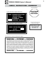
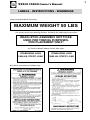
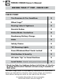
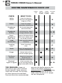
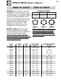
Owner’s
Manual
PHONE (
) _____________________________________
STATE _____________ ZIP _______________________________
CITY _________________________________________________
ADDRESS ____________________________________________
DEALERSHIP NAME ___________________________________
TIRE SIZE ____________________________________________
AXLE SIZE ___________________________________________
HITCH SIZE ___________________________________________
KEY LOCK NUMBER __________________________________
MODEL NUMBER ____________________________________
SERIAL NUMBER _____________________________________
DATE PURCHASED ___________________ 20 ___________
(Feed this side if using a typewriter)
Owner’s Manual
ABOUT YOUR NEW WELLS CARGO TRAILER
Now is the right time to complete the information below for
your permanent record. Use a typewriter or print clearly. You will
also need this Quick Reference when contacting Wells Cargo or a
Wells Cargo Dealership regarding your Warranty, Service, Repair,
or Replacement parts.
Owner’s Manual
TABLE OF CONTENTS
MESSAGE FROM THE PRESIDENT ..................................... Page 2
ABOUT THIS MANUAL ....................................................... Page 3
DEALERS & SERVICE ......................................................... Page 3
LABELS - INSTRUCTIONS - WARNINGS ............................. Pages 4-8
NOTES ................................................................................ Pages 9
BEFORE YOUR 1ST TRIP - CHECK LIST............................... Pages 10
ROUTINE MAINTENANCE - CHECK LIST ............................ Pages 11-12
WHAT TO CHECK & HOW TO CHECK ................................. Pages 13-14
WARRANTY PROGRAM & CARD ....................................... Pages 15-18
WHAT TO CHECK & HOW TO CHECK (con’t) ..................... Pages 19-22
12-VOLT ELECTRICAL SYSTEMS ........................................ Pages 23-25
PLUMBING ......................................................................... Pages 26
MISC. INFORMATION ........................................................ Pages 27-29
TIRE SAFETY INFORMATION ............................................. Pages 30-32
PLANT LOCATIONS ............................................................ Pages 33
REPORTING SAFETY DEFECTS ........................................... Below
REPORTING SAFETY DEFECTS
If you believe that your vehicle has a defect which could cause
a crash or could cause injury or death, you should immediately
inform the National Highway Traffic Safety Administration
(NHTSA) in addition to notifying Wells Cargo, Inc. If NHTSA
receives similar complaints, it may open an investigation, and
if it finds that a safety defect exists in a group of vehicles, it
may order a recall and remedy campaign. However, NHTSA
cannot become involved in individual problems between
you, your dealer, or Wells Cargo, Inc. To contact NHTSA,
you may either call the Vehicle Safety Hotline toll-free at
1-888-327-4236 (TTY: 1-800-424-9153); go to http://www.
safercar.gov, or write to: Administrator, NHTSA, 1200 New
Jersey Avenue S.E., Washington, DC 20590. You can also obtain
other information about motor vehicle safety from
http://www.safercar.gov.
1
2
Owner’s Manual
WITH A WELLS CARGO BEHIND . . . YOU NEVER LOOK BACK!
Jeffrey M. Wells
President
Wells Cargo, Inc.
We hear it all the time, “My Wells Cargo pulls so well,
I can hardly tell it’s there.” There’s a reason why a Wells
Cargo delivers such smooth towing and stable handling. We
build them better! Experience makes a difference, and our
experience is unmatched in the industry. Since 1954, we’ve
combined State-of-the Art Design with the best materials
available to manufacture our trailers.
There’s another reason for our slogan, “With a Wells
Cargo Behind . . . You Never Look Back!” We never want
you to “look back” or second guess your decision to buy
a Wells Cargo trailer. That’s why we support you with a
comprehensive Warranty Program that really works for you.
Owner’s Manual
ABOUT THIS MANUAL . . . DEALERS & SERVICE
OUR PRODUCT
Wells Cargo builds ball coupler
and gooseneck trailers in several
basic configurations. Most trailers
we build are customized on our
production lines by the inclusion of
one or several optional features as
specified by the dealer or customer.
The list of options runs into the
hundreds of possible combinations.
OUR BRANDS
Wells Cargo manufactures five
different model lines: Wells
Cargo , Road Force®, TC Trecker®,
MotorTrac®, and Silver Sport . This
manual primarily addresses the
Wells Cargo line since it represents
our most comprehensive brand
with the most sizes, configurations,
options, and customizing. However,
all our trailer lines feature similar
characteristics, components,
features, and assemblies. For
that reason, almost all the topics
addressed in this Owner’s Manual
are applicable to all lines. There
may be slight variations, but the
overall concepts are universal.
TM
TM
THIS MANUAL
This manual covers only the basic
trailer and standard components.
Information and warranty details
for any optional equipment are
available from Wells Cargo or any
Wells Cargo Dealer.
WELLS CARGO DEALER
Authorized Wells Cargo Dealers
are responsible business people
who have lengthy backgrounds
in cargo trailers. They have in
depth knowledge about trailer
construction, job specifications
and proper applications of specific
models. They’re equipped to
handle your service effectively and
efficiently.
NATIONAL
SERVICE NETWORK
Wells Cargo has manufacturing facilities in Phoenix, Arizona;
Waycross, Georgia; Elkhart, Indiana;
Waco, Texas; Ogden, Utah; and
Carbondale, Pennsylvania. Each
manufacturing plant operates a
Customer Service Facility. With
the additional Service Facilities
at hundreds of Authorized Wells
Cargo Dealerships nationwide you
are never far from a convenient
location for service work anywhere
you travel.
IMPORTANT:
We urge you to become familiar
with the contents of this manual.
Following the basic directions is
your key to the safe operation of
your Wells Cargo Trailer. It is also
the best way to ensure that you
keep the full protection of your
Warranty.
CALL 1-800-348-7553
For Nearest Location or Any
Other Questions
3
4
Owner’s Manual
LABELS - INSTRUCTIONS - WARNINGS
Check your new Wells Cargo trailer for Instructional & Warning Labels like
the ones listed below. Many are mandated by the Federal Government
and others will help you in proper and safe operation. If decals become
faded or damaged to the point where they are unreadable, please contact
Wells Cargo for replacement. The information below is included in the
event a label is missing.
Located At Lift-Up Nose Cone®
NOTICE
LUBRICATE ALL PIVOT POINTS WITH
SAE 30 WEIGHT OIL A MINIMUM OF
TWO TIMES PER YEAR
WARNING
BE SURE TO
Connect Appliance First
At Propane or
Natural Gas Appliance
and check before you
connect gas bottles to line.
APPLIANCES ARE NOT
CONNECTED AT
FACTORY
Law requires that
an authorized competent
service man ONLY can complete
this installation.
At Ride-In Entry
i.e. Snowmobiles, Motorcycles
CAUTION - LOW CLEARANCE
At Transfer Switch or Junction Box
GENERATOR CIRCUIT. THIS
CONNECTION IS FOR
GENERATORS RATED
110-125 VOLT AC,
60HZ ______AMPERES
MAXIMUM.
At Transfer Switch or Junction Box
AIR COND. CIRCUIT. THIS
CONNECTION IS FOR
AIR CONDITIONER RATED
110-125 VOLT AC.
60HZ ______AMPERES
MAXIMUM
5
Owner’s Manual
LABELS - INSTRUCTIONS - WARNINGS
At Ramp Doors
At Outside Power Supply Connection
THIS CONNECTION FOR
120/240 VOLT,
3-POLE, 4 WIRE,
60 HERTZ,
AMPERE SUPPLY
At Outside Power Supply Connection
CAUTION
DO NOT STAND
UNDER DOOR WHEN
RAISING & LOWERING
Located at Breakaway
Switch Test Light
PULL PIN TO TEST
FOR 110/125 VOLT, AC
60 HZ.30
AMPERE SUPPLY.
LIGHT INDICATES
BATTERY O.K.
Located with Customer Information Papers
WARNING — EXTREME — DANGER
The “RAMP-HEISTER” torsion spring assembly has been carefully selected
and installed by the manufacturer of this trailer. It has been designed to counterbalance the weight transferred when opening and closing the entrance
ramp. The entire torsion spring assembly, mounting hardware and cables are
loaded with tremendous energy. Repairs or adjustments by inexperienced
persons or without proper tools is hazardous and could cause severe personal
injury or death. Do not attempt to remove or repair any door components,
hardware or the structure that these components are attached to. Periodic
inspection or the entire assembly, to include but not be limited to, cable
wear, fastener integrity and proper lubrication, is required. ALL REPAIRS
OR ADJUSTMENTS MUST BE PERFORMED BY EXPERIENCED DOOR
SERVICE PERSONNEL ONLY!
WARNING — EXTREME — DANGER
6
Owner’s Manual
LABELS - INSTRUCTIONS - WARNINGS
Federal I.D. Plate - Mounted Road Side Lower Front Corner
Tire Placard - Mounted Road Side Lower Front Corner
Manufacturers I.D. Plate - Mounted Road Side Lower Front Corner
SINCE 1954
DESIGN PROTECTED BY TRADEMARK LAW
ELKHART, IN
WAYCROSS, GA
WACO, TX
OGDEN, UT
PHOENIX, AZ
CARBONDALE, PA
TELEPHONE: 1-800-348-7553
Owner’s Manual
LABELS - INSTRUCTIONS - WARNINGS
Aluminum Roof Rack Cross Bars
MAXIMUM WEIGHT 50 LBS
For trailers with rear spotting hitches. Primarily for Cable Splicing trailers.
REAR HITCH ASSEMBLY NOT TO BE
USED FOR TOWING PURPOSES.
FOR PLACEMENT ONLY!
At Trailer Sidewall above Corner Post Jacks
STABILIZING JACK
2000 LB. STATIC LOAD
Ball Hitch Instruction and Warnings
STABILIZING JACK
3000 LB. STATIC LOAD
7
8
Owner’s Manual
LABELS - INSTRUCTIONS - WARNINGS
Located above lock assembly on MPT models only.
On Wells Cargo and Road Force trailers with 3,500 lb. to 8000 lb. axles. Located
behind fender/fenderette as low as possible.
Owner’s Manual
NOTES
9
10
Owner’s Manual
BEFORE YOUR 1ST TRIP - CHECK LIST
CHECK POINT:
Tire Pressure & Tire Condition
X
Wheel Lugs*
X
Bearing Lube & Tightness
X
Burnish Brakes
X
Brakes/Brake Controllers
X
Breakaway Battery Charge
X
Hitch
X
Safety Chains
X
12V Running Lights
X
Doors/Windows/Roof Vents Locked
X
Distribution & Security
X
All Jacks “Up” in Travel Position
X
Level Trailer (Parallel with ground & tow vehicle)
X
*Check Lug Nuts for tightness before initial trip, at 10 miles,
25 miles and 50 miles. Recheck at least every 3 months or
3000 miles.
Your Wells Cargo Dealer, in all probability, checked each of these Points
before you took delivery. However, these are key things you should recheck before taking your trailer on the road for the first time.
A complete description of how to properly
check these Points starts on Page 10.
11
Owner’s Manual
ROUTINE MAINTENANCE CHECK LIST
EVERY
TRIP
CHECK:
WHAT TO DO:
Tire Air
Pressure
Inflate to Proper Pressure
Indicated on Sidewall
Wheel Lugs
Bolts & Nuts
Tighten to Proper
Torque Specifications
Wheel
Check for Damage
and/or
Out of Round
Coupler Ball
Check for Sufficient Lube.
or
Check Lock Mechanism.
5th Wheel & Pin Check for Unusual Wear.
Coupler
Check for proper
fastening & Hitch Pin in
position and secure
•
•
•
EVERY
3000 Mi.
or 3 Mo.
EVERY
6000 Mi.
or 6 Mo.
See Page
# for
Details
10
•*
11
•
11
12
12
*Check Lug Nuts for tightness before initial trip, at 10 miles,
25 miles and 50 miles. Recheck at least every 3 months or
3000 miles.
AXLES • HUBS • BRAKES: Your Wells Cargo trailer is equipped with
Dexter Axles. The Dexter Operation Maintenance Service Manual, along
with additional reference materials, can be found inside your trailer’s
service packet. Replacement copies are available from your Wells Cargo
dealer. You can also find useful axle related information by visiting the
Dexter Axle On-line Trailer Resource Library at:
www.dexteraxle.com/resource_library
Maintenance for Axles, Hubs and Brakes is extremely important. It is
critical for protecting the longevity of your trailer. It is also vital for your
personal safety and the protection of others. Follow the Dexter service
recommendations exactly as described.
Please, never shortcut Axle • Hub • Brake service and maintenance.
12
Owner’s Manual
ROUTINE MAINTENANCE CHECK LIST
EVERY
TRIP
CHECK:
WHAT TO DO:
Safety
Chains
Check for abrasion,
distortion and general
integrity of links
Brakes
Check for proper
adjustment & operation
Breakaway
Switch
Test Switch Operation
and Connections
Breakaway
Battery
Pull Switch Pin, Check
Charge Indicator Light
Doors,
Windows &
Roof Vents
Check all Windows/Doors/
Roof Vents. Make sure all
are closed & locked
Load
Distribution
Check Load Distribution
& Security
Leveling
Jacks
Check Fastenings.
Lube.
Welds
Check All Weld Beads for
Cracks or Separations.
Hinges
Grease zerks with a
Lithium complex grease.
Tie-Down
Devices
Check for fracturing,
distortion and
improper anchoring.
Electrical:
Lights & Signals
Check to make sure
all are working properly.
Replace burned out bulbs
TIRE PRESSURE: Proper air
pressure for your tires is printed
on the sidewall. Check pressure
while tires are cold. Do not raise
or lower pressure to meet load.
Pressure other than recommended
EVERY
3000 Mi.
or 3 Mo.
•
•
•
•
•
•
•
•
EVERY
6000 Mi.
or 6 Mo.
See Page
# for
Details
14
19
19
19 - 20
21
21
21
•
•
•
22
22
22
23 - 25
pressure will lead to excessive tire
wear or tire failure. Balancing
recommended. Preferred Balancing
Method is to center off of stud
holes, since 13” thru 17.5” wheels
are not hub piloted.
13
Owner’s Manual
WHAT TO CHECK . . . HOW TO CHECK
WHEELS: Check Wheels for hole
elongation or “out of round”. This
condition can be caused by Lug Nuts
not being tight, or too tight. Trailer
wheels can be damaged by chuck
holes or curb jumping. You may not
be aware of the road shock to the
wheels without periodic checks.
Replace any wheel that is bent.
Replace any wheel if you see
elongation of the bolt holes.
WHEEL LUGS: Wheel Lug Nuts
must be tightened with a torque
wrench. Refer to the chart below for
proper torque for your trailer.
Check Lug Nut tightness before
initial trip, at 10 miles, 25 miles and
50 miles. Recheck at least every 3
months or 3000 miles.
TORQUE STAGES
1st Stage
20/25
ft. lbs.
2nd Stage
3rd Stage
40/50
ft. lbs.
Full Torque
Note: Warranties on trailer and
axle do not apply to damage
or injuries caused by loose or
improperly tightened lug nuts
or broken studs.
AXLE
SIZE
WHEEL
SIZE
STUD
SIZE
STEEL WHEEL
TORQUE
ALUMINUM WHEEL
TORQUE
2000#
13”
1/2”
50# - 75#
N/A
2000#
14”
1/2”
90# - 120#
N/A
2000#
15”
1/2”
90# - 120#
90# - 120#
2500#
15”
1/2”
90# - 120#
90# - 120#
3500#
13”
1/2”
50# - 75#
N/A
3500#
15”
1/2”
90# - 120#
90# - 120#
5000#
15”
1/2”
90# - 120#
90# - 120#
6000#
15”
1/2”
90# - 120#
90# - 120#
6000#
16”
1/2”
90# - 120#
90# - 120#
7000#
16”
1/2”
90# - 120#
90# - 120#
7000#
16”
9/16”
90# - 120#
90# - 120#
7000#
16”
5/8”
275# - 325#
275# - 325#
7200#
16”
9/16”
90# - 120#
90# - 120#
7200#
16”
5/8”
275# - 325#
275# - 325#
8000#
17.5”
5/8”
275# - 325#
275# - 325#
14
Owner’s Manual
WHAT TO CHECK . . . HOW TO CHECK
BALL COUPLER HITCHES:
Coupler Assembly includes a Latch
Lever, and Latch Lever Safety Pin or
Hitch Pin. Be sure the Latch Lever is
locked and the Pin properly secured
before moving your trailer. The Pin
can be engaged fully only if the Ball
is properly seated in the Coupler.
Latch in Down
Position
require a SAE 2” King Pin or 5th
Wheel. Hitch D, (the Adjustable
Height Ball Coupler Goose Neck)
requires a 2 5/16” Hitch Ball with a
rating equal to the GVWR of the
unit.
Gooseneck Hitch Types
Safety Pin
Inserted & Secure
A. Inverted 5th Wheel
B. Adjustable Hgt.
C. Articulating
D. Adjustable Hgt.
King Pin
Ball Hitch Assembly
HITCH BALLS come in a variety
of diameters and capacities. The
GVWR capacity is always stamped
on the Ball. Wells Cargo trailers
use either a 2” Ball or a 25/16” Ball
depending on the GVWR of the
trailer. Always be sure the Hitch Ball
at least matches the GVWR of your
trailer. Always be sure the diameter of
the Hitch Ball matches the Coupler
diameter. Never attempt to tow
your trailer with improper size Ball.
Always keep Ball greased to avoid
excessive wear. Replace worn Hitch
Balls or Locking Dogs promptly.
GOOSENECK HITCHES: Your
Wells Cargo Gooseneck Trailer
will be equipped with one of four
hitch types pictured below. Be sure
the King Pin or 5th Wheel on tow
vehicle is rated for at least as much
weight as the GVWR of the Trailer.
Hitches (A, B & C pictured below)
5th Wheel
Ball Coupler *
*Note: Ball Coupler Hitch (D.) requires Safety Chains
Recommended: Mount King Pin or
5th Wheel Hitch on the bed of the
tow vehicle. This lowers the center
of gravity for easier and safer
handling. Replace worn Hitch Pins
and 5th Wheel Jaws promptly.
Check with Tow Vehicle Manufacturer, Owners
Manual or Local Dealership for any Hitch installation
requirements. Hitches installed otherwise may void
your tow vehicle warranty.
SAFETY CHAINS: Your Wells
Cargo Trailer is equipped with Safety
Chains that meet the requirements
of D.O.T. Regulations 393.70.
Always attach the Chains by crossing
them, forming a “cradle”. If your
Coupler disengages for any reason,
the “cradle” will keep the Hitch from
dragging the ground. You’ll be able
to make an easier and safer stop.
Owner’s Manual
NEVER LOOK BACK WARRANTY PROGRAM
WELLS CARGO, INC. LIMITED WARRANTY
DURATION OF WARRANTY
Your Wells Cargo equipment, which has been manufactured, tested and inspected
in accordance with carefully specified engineering requirements, is warranted to
the original owner to be free from defects in material and workmanship for the
period of six (6) or four (4) or three (3) years depending on the brand/model*,
except as herein limited, from date of purchase. The obligation of this Warranty
shall be limited to repairing or replacing any part or parts which, in the opinion of
the Company shall be proved defective in materials or workmanship under normal
use and service during the appropriate year(s) period commencing with the date
of purchase. Jack rams, electrical wiring, glass sealants, doors, seals, locks, paint,
plumbing, couplers and jacks are warranted for a period of one (1) year from the
date of purchase. The D.O.T. Wet Cell Battery (Breakaway System) is warranted for
a period of six (6) months from the date of purchase.
This Warranty gives you specific legal rights, and you may also have other rights
which vary from State to State.
*Length of Warranty by brand/model:
6-Year Warranty
4-Year Warranty
MT1000 — 3-Year Warranty
MT2000 & MT4000 — 6-Year Warranty
3-Year Warranty
3-Year Warranty
15
16
Owner’s Manual
NEVER LOOK BACK WARRANTY PROGRAM
LIMITATIONS AND EXCLUSIONS
This Warranty shall not extend to:
1) Wells Cargo equipment which has been modified, repaired, or altered
in any way without the express written consent of Wells Cargo.
2 ) Unreasonable use (including failure to provide reasonable and
necessary maintenance.)
3) Tires, wheels, axles, axle assemblies, suspension components, ranges,
heaters, refrigerators, air conditioners or all other appliances or
components of the Wells Cargo equipment which are warranted
separately by the respective manufacturers of said components. These
warranties are contained in the owner’s packet.
4) Any consequential damages for breach of this or any other warranty
expressed or implied whatsoever. Repair or replacement under this
Warranty is the exclusive remedy of the customer. Some States do
not allow the exclusion or limitation of incidental or consequential
damages, so the above limitation or exclusion may not apply to you.
5) Parts not supplied by Wells Cargo.
6) Certain parts which require replacement in the ordinary course of use
due to normal wear.
PROCEDURE
To secure repair of a trailer or any warranted parts under this Warranty,
the unit or warranted part must be delivered, charges prepaid, to the
nearest Wells Cargo Dealer or Wells Cargo manufacturing facility or as
directed by the Company.
Your Wells Cargo dealer from whom you purchased your unit is
responsible for the registration of your warranty with the factory. We
ask that you cooperate with your dealer in supplying the necessary
information on the warranty card so that we may better serve you.
Please Note: Should equipment not supplied by Wells Cargo fail, (e.g. the
hitch you have installed on your tow vehicle), the result may be an accident,
damage or injury beyond our control.
Wells Cargo, Inc. Warranty Registration
Please complete & return card promptly.
NAME: _______________________________________________________________
COMPANY: ___________________________________________________________
ADDRESS: ____________________________________________________________
CITY: _______________________________________ STATE: _________________
ZIP CODE: _________________ COUNTRY: ________________________________
PHONE: ( ________ ) _________________ FAX: ( ________ ) _________________
EMAIL: ______________________________________________________________
Moving/Relocating
Marching Band
Mobile DJ
Musician/Band
Photography/Video
Radio/TV
Hunting
____________________
SERIAL NUMBER: ______________________________________________
MODEL NUMBER: _____________________________________________
DATE PURCHASED: ____________________________________________
DEALER NAME
and/or NUMBER: ______________________________________________
Manufacturer
Distributor
Retailer
Public Utility
Government Agency
School/College
Church/Service Group
Agricultural/Animal
Moving Company
HAZMAT Response
Fire/Police/Medical
Landscape
Ground Maintenance
Nursery
Sales/Display
Restroom Trailers
Construction (Gen.)
Mechanical Contractor
Electrical Contractor
Painting Contractor
Remodeling Contractor
Roofing/Siding/Gutter
Insulation
Furniture/Cabinets
Concessionaire
Catering
Restaurant
Delivery Service
Misc. Service
Rental/Leasing
Utility Companies
__________________
Where have you seen Wells Cargo Advertised? __________________________________________________________________________
Auto Racing
Auto Collector
Karting
Camping/RV
Scouting
Arts & Crafts
Antiques
Toy Hauler
Please check the planned use of your Wells Cargo trailer:
Motorcycles
Snowmobiling
ATV
Bicycles
BMX
RC Models
Ballooning
Living Quarters
PERMIT NO. 588
WELLS CARGO INC
PO BOX 728
ELKHART IN 46515-9908
FIRST-CLASS MAIL
ELKHART, IN
BUSINESS REPLY MAIL
NO POSTAGE
NECESSARY
IF MAILED
IN THE
UNITED STATES
Owner’s Manual
WHAT TO CHECK . . . HOW TO CHECK
BREAKAWAY SWITCH & D.O.T.
WET CELL BATTERY: After hitching
Safety Chain Hook-Up
Abrasion (possibly from dragging
on the ground) or unusual stress
(like the situation described above)
can weaken the links, making them
unsafe for trailering. If you detect
any of these conditions, replace the
Safety Chains immediately! If safety
chains are too long, shorten to prevent dragging. DO NOT TWIST!
BRAKES: Your Wells Cargo Trailer
is equipped with one of several
Brake type options. Complete
service and repair information for
each available type brake is found
in the Dexter Service Manual that
is furnished with your Trailer. It is
important to strictly adhere to the
Dexter instructions for brake service
and repair. In this way, you are protecting the validity of all applicable
Warranties.
BURNISHING BRAKES: Brakes
on a new trailer may tend to
“grab”, or pulsate. This is normal.
To correct the situation, pull the
trailer with the trailer brake control
slightly engaged a short distance.
This action smooths down the
brake bands. Do not lock up the
wheels.
to Tow Vehicle, pull the Safety Pin
on the Breakaway Switch to the
first position (no need to completely
remove pin). If the Test Light appears,
battery is charged and the system is
operational. Push Safety Pin back in
to its original position. Check Battery
fluid level every 60-90 days. Remove
Cover. There are two Fill Caps. Refill
with distilled water, only. Your
Breakaway assembly is equipped with
a Charge Line. (See Wire Diagrams,
Page 20-21) Tow vehicle must also
be wired for a charge line to keep
Breakaway Battery charged. During
long periods of idleness, keep wet
cell battery charged using a trickle
charger. A discharged battery can
freeze and crack in winter.
BATTERY STORAGE: Before storing
your battery, you should:
1.) Clean the battery case and
terminals with baking soda and water
2.) Check the water level and add
water if needed
3.) Test your battery with a
hydrometer and/or voltmeter to
ensure the battery is fully charged.
4.) If needed, charge your battery.
Batteries stored in a discharged state
are susceptible to freezing, sulfation
and an increased rate of discharge. A
fully charged battery will not freeze
unless the temperature reaches
approximately 800F below zero. But if
discharged, it can freeze at 320F.
Store your battery in a dry, cool, wellventilated area—the cooler the better
without going below 320F—out of
reach of children and pets. Check the
water level and state of charge every
45-60 days. If needed, add distilled
water and charge.
19
20
Owner’s Manual
WHAT TO CHECK . . . HOW TO CHECK
Breakaway Switch & Test Light - Mounted on A-Frame
Junction Box
Cable in straight line
to vehicle*
Power Cable
Test
Light
* Attach Breakaway Switch Cable securely to tow vehicle. Locate attachment so
little “slack” is left in the Cable; but enough slack to allow for turning without
disengaging Pin. Thus, the Cable will activate brakes the instant a trailer becomes
disengaged. Brake adjustment is critical to stopping a disengaged trailer.
Breakaway Battery on A-Frame
Two Fill
Caps
Underneath
Cover
CHECK BREAKAWAY SYSTEM & BRAKES BEFORE EACH TRIP
1. Disconnect 12V Plug from tow vehicle
2. Pull Breakaway Pin. If RED Test Light appears, there is adequate charge for
battery to function.
3. While Pin is pulled, move tow vehicle forward. Brake should be on & wheels
locked.
4. Replace Pin and secure to tow vehicle. Do not loop over Hitch Ball.
5. Plug 12V Connector into tow vehicle receptacle.
6. Test Brakes with Brake Controller.
NOTE: When disconnecting trailer from tow vehicle, make sure to replace Safety pin
on the Brakeaway Switch. Failure to replace Safety Pin will drain battery and render
the Brakeaway System useless. The Breakaway System should NEVER be used as a
parking brake. Also, the wet cell battery is dedicated to the Brakeaway system only.
DO NOT run any other charges (i.e., dome lights) from this battery.
21
Owner’s Manual
WHAT TO CHECK . . . HOW TO CHECK
DOORS, WINDOWS & VENTS:
Before towing your trailer, check
that all doors, windows and roof
vents are closed and latched.
Make sure all closing mechanisms
are functioning properly and are
secured. Cam Lock Door Closures
should be fully engaged. Single
Doors with Flush Locks should be
locked. Using padlocks on all doors
is added insurance against accidental
opening from road shock. Taking
the above measures means you can
travel without danger of doors and
windows accidentally opening.
DOOR HOLD BACKS: These
devices are intended to hold a door
open in grade deviations only. Do
not rely on them to hold door open
in windy conditions or in travel.
LOAD DISTRIBUTION: The total
weight of the load you put in or on
your trailer, plus the empty weight
of the trailer itself, must not exceed
the trailer’s Gross Vehicle Weight
Rating (GVWR). In addition, you
must distribute the load in the
trailer such that the load on any
tire or axle does not exceed the
tire load rating or the Gross Axle
Weight Rating or GAWR.
Uneven load distribution can cause
tire, wheel, axle or structural failure.
Be sure your trailer is properly
loaded. A proper weight distribution
is equal, right to left; and creates a
hitch weight that is in the proper
range for stable trailer handling.
In the table that follows, the
second column notes the “rule
of thumb” percentage of total
weight of the trailer plus its cargo
(GVW) that should appear on the
hitch of the trailer. Consider these
percentages as guidelines for Ball
Hitch, V-Front and Gooseneck trailers
respectively. Actual percentages may
vary. Many factors including optional
equipment, trailer configuration,
towing angle, and load factor
can and will affect hitch weight.
Never exceed the hitch weight
rating stamped on your tow
vehicles coupler.
TYPE OF
HITCH
HITCH WEIGHT
%
Ball Hitch
V-Front
Gooseneck
10% to 15%
10% to 15%
25%
Overloading, uneven load
distribution, and improper hitch
weight can result in dangerous
driving conditions resulting in
loss of control of the trailer.
STABILIZER/LEVELING JACKS:
Always block tires before and
while using Leveling Jacks! Failure
to block tires can result in failure
of the Jacks or Stabilizers. This, in
turn, can cause property damage
and/or personal injury. Stabilizer
Jacks (Cornerpost or Swing-Down)
installed as original equipment
by Wells Cargo have static load
capacities ranging from 650 to 3000
lbs. (See label affixed near jack for
exact capacity.) Consult individual
Manufacturer’s Owners Manual for
capacity and rating for all Manual
and Electric Leveling Jacks.
22
Owner’s Manual
WHAT TO CHECK . . . HOW TO CHECK
WELDS: Every 6 months or 6,000
miles, check all welds for fractures
or cracks. Also, check steel surfaces
around the welds for any sign of
cracking. If you do detect any of
these conditions, immediately
contact your Wells Cargo Dealer, or
call Wells Cargo.
HINGES: Keep Hinges clean and
clear of salt and road dirt. Proper
maintenance will keep hinges
from binding or freezing. Newer
models: Steel hinges with a free
flow pin and a grease zerks require
greasing every 3 months. A Lithium
complex grease is adequate for this
routine maintenance. Older models:
Lubricate with WD 40 or equivalent
light oil.
TIE-DOWN DEVICES (ALL):
Check regularly for any signs of
fracturing, distortion and improper
anchoring. Replace as needed.
TRAILER BODY: Keep your trailer
clean, both interior and exterior.
The exterior metal skin, roof caps,
and wheels (standard, chrome, and
aluminum) should be waxed at
least once a year — more often if
needed. Any anodized aluminum
including the roof cove and trim
accents should be cleaned with a
mild detergent, rinsed thoroughly,
and waxed as well. Do not use
excessive abrasive cleaners as it may
mar the protective finish. Make
sure to touch up scratches. Scratches
on the A-Frame and any exposed
steel parts should be sanded,
primed, and painted. Regular attention to these simple details will
maintain the attractive appearance
of your trailer. It will also help
increase the service life and resale
value already inherent in your
Wells Cargo trailer.
GENERAL APPEARANCE: Just
like an automobile, your trailer’s
exterior skin will look better longer
if washed regularly. Dirt, road salt,
acid rain, and air pollution can cause
unsightly stains. If caught early,
stains can be cleaned with a mild
detergent. If left unattended, stain
removal may require a commercial
grade cleaner; or worse cause
permanent damage. Call the Wells
Cargo Parts Department at
1-800-348-7553 for cleaner
recommendations.
SNOW LOAD ON TRAILER
ROOF: Remove excess snow from
the roof of your trailer. Units
that sit for an extended period of
time can accumulate an excessive
amount of snow and ice. This can
cause your roof to collapse.
SNOW MELT AND WATER
DAMAGE: Do not allow water to
accumulate and pool inside trailer.
(Example: snow melt off snowmobile.)
Over time, this could cause interior
floor damage and shorten the
life of your trailer. Open the rear
door(s) and “jack-up” the front of
your trailer. This allows the water
to drain out the rear.
Owner’s Manual
12 VOLT ELECTRICAL SYSTEMS - 4, 6 & 7 CIRCUIT CONNECTORS
RACEWAY: Your Wells Cargo
Trailer may be equipped with a twopiece, molded snap-a-part wiring
Raceway mounted inside, at the
roof line. The Power Cable enters
the Raceway at the front wall, and
supplies connection for all internal
and external 12 Volt Lighting. There
are NO under carriage splices or taps
in the lighting circuits. If you wish to
add other lighting in the future, all
connections can be made within the
snap-a-part Raceway.
TROUBLE SHOOTING: The
Raceway provides easy access
for trouble shooting should you
develop any problems. Circuits
can be individually connected or
disconnected for testing purposes.
Example: Should a Tail Light Fuse
blow and continues to blow,
disconnect all Brown wires from
the Main Cable. Replace Fuse.
Reconnect one Brown wire at a
time until Fuse blows again. This
last wire, then, is the problem.
Disconnect it. Reconnect all other
wires, and check for lights that
are not lit .The problem will be
a malfunctioning fixture, or a
grounded wiring. Use the same
procedure to trouble shoot
any other circuit. Some trailer
models are not equipped with
the Raceway. Instead, they have a
Junction Box located at the interior,
road side rear. The main 12V power
cable feeds through the road side
Frame Rail and through the Rear
Corner Post to the Junction Box.
All distribution for 12V, interior and
exterior lighting feeds through the
Junction Box.
All checks and trouble shooting can
be done at the Junction Box. There
are no under carriage splices or taps.
A NOTE ABOUT WIRING YOUR
TOW VEHICLE: The electrical
system for your trailer is protected
by the circuit protection system
in your tow vehicle. When “hot
lines” are added for brakes and
accessories, this wiring should be
fused in the tow vehicle. Never
use existing tow vehicle wiring for
these lines. Run new wiring directly
to the Plus (+) side of the tow
vehicle battery. Never use circuit
breakers for circuit protection
when installing these lines. Use
12 gage wire (minimum) for both
the brake and accessory wires. Do
not exceed a 30 amp fuse on the
brake line and a 20 amp fuse on
the accessory line.
TOW VEHICLES (Foreign
makes): Most foreign made tow
vehicles have amber turn signals
with separate brake and turn signal
wiring. In order for the trailer’s
lights to work properly, one must
install a special tail light converter
to the tow vehicle. This converter
allows the different wiring
configurations of the tow vehicle
and trailer to be compatible. Most
RV and trailer parts supply stores
carry this special converter.
23
TM
S
LT RT
GREEN -
(RT) - Right Stop & Turn Lights
YELLOW - (LT) - Left Stop & Turn Lights
- D.O.T. Breakaway (Wire running from Breakaway Switch thru Junction Box to D.O.T. Battery)
SAE WIRING CODE: The wire colors indicated above are according to this Code. Additional Code Colors: PURPLE - Optional, ORANGE
RT - Right - Stop & Turn
LT - Left - Stop & Turn
GD A
(A) - Auxiliary - Dome, Charge Line etc.
BLACK -
A - Aux, Charge Line
(TM) - Tail, Running & License Lights
BROWN -
TM -Tail, Running, &
License Lts.
(S) - Electric Brake
BLUE -
6 TERMINAL
CONNECTOR
(GD) - Common Ground to Frame
GREEN - Right Stop & Turn
S - Electric Brake
TRAILER
LT RT
WHITE -
TOW VEHICLE
GD TM
BLACK - Dome & Other Aux. Lts.
BROWN - Tail, Running & License Lts.
4 TERMINAL
CONNECTOR
GD - Common Ground
Right - Stop & Turn
YELLOW - Left Stop & Turn
BROWN -Tail, Running, &
License Lights
Tail, Running, License & Aux. Lts.
Left - Stop & Turn
WHITE - Ground to Frame
TRAILER
Common Ground
TOW VEHICLE
24
Owner’s Manual
12 VOLT ELECTRICAL SYSTEMS - 4, 6 & 7 CIRCUIT CONNECTORS
Owner’s Manual
( 7 ) Not Used
CABLE WIRING CODE:
Yellow and Green - 18 gauge
Brown - 16 gauge
Black - 12 gauge
PURPLE -
( 5 ) Left - Stop & Turn
YELLOW -
( 6 ) Right - Stop & Turn
( 4 ) Auxiliary, Dome Light, Charge Line etc.
BLACK -
GREEN -
( 3 ) To Tail, Running & License Light
BROWN -
( 2 ) Electric Brake
BLUE -
( 1 ) Common Ground to Frame
12 VOLT WIRING SYSTEM: All
12V Electrical Power is supplied
from the tow vehicle to your trailer
through one of the Circuit Connectors
diagrammed at the left. All wiring is
color coded according to SAE Code.
The trailer half of the connector
is attached to a flexible, jacketed
Power Cable running to a Junction Box.
(see upper, right hand illustration
- Page 16). From the Junction Box,
the Cable then runs through the
road side frame channel.
The Brake Line exits the Frame at
the Axle, and connects to the Axle
Wire via a water tight boot. Wire
and boot are anchored to the Frame
with Ring Clamp and Fastener.
No. 7 - Auxiliary
No. 6 - Right Stop & Turn
No. 5 - Left Stop & Turn
No. 4 - Battery Charge
No. 3 - Tail, Running &
License Lts.
No. 2 - Electric Brake
Common Ground
No. 1 -
TOW VEHICLE
6
2
4
7
3
1
5
TRAILER
WHITE -
7 TERMINAL
CONNECTOR
12 VOLT ELECTRICAL SYSTEMS - 4-6 & 7 CIRCUIT CONNECTORS
WARNING: FOR TRAILERS
WITH BREAKAWAY SYSTEM!
Tow vehicle must be equipped
with a fused, 20 Amp Charge Line
connected to Pin 4 of the trailer
Connector.
25
26
Owner’s Manual
PLUMBING
WINTERIZING PLUMBING: After
draining the system, close all of the
drain valves, except the one that
drains the water heater. (See 1 )
Leave that one open. We have
added five shut off valves to our
water piping to accommodate RV
Non-Toxic antifreeze. Two of the
valves are located on the suction side
of the water pump. The first one
disconnects the water storage tank.
(See 2 ) It is normally open. Turn it
off. The second valve on the suction
side of the water pump opens the
siphon tube (See 3 ) and can be
opened up after the siphon tube is
Owner’s Manual
MISC. INFORMATION
WINTERIZING PLUMBING (con’t):
dipped into a gallon of RV Non-Toxic
antifreeze. The other three valves
are located right at the water heater
and make it possible to leave the
water heater full of air, while the hot
and cold lines are filled with RV NonToxic antifreeze. Shut off the valve
that fills the water heater with cold
water. (See 4 ) Shut off the valve
that is located on the hot water line
off the water heater (See 5 ) Open
the valve that joins the hot water
lines and the cold water lines (See
6 ) This allows you to bypass the
water heater and still fill both the
hot and cold water lines. NOW YOU
ARE READY. Slip the dip tube into a
gallon of RV Non-Toxic antifreeze,
with the valve open (See 3 ), and
turn on the water pump. Open one
faucet or toilet at a time until you
see RV Non-Toxic antifreeze. When
finished, the lines are full. Be sure to
flush enough RV Non-Toxic antifreeze
into the sinks so that the traps are
protected as well.
SPECIALIZED PLUMBING: If you
have a trailer with a specialized
plumbing application, unlike the
one shown on the previous page,
these types of plumbing systems will
need to be drained and winterized
properly as well.
PROPER TRAILER LIFTING PROCESS:
Make sure that the trailer is properly
blocked or the brakes are applied
to prevent the trailer from moving
while the trailer is being jacked up.
A Torflex® Axle should have the
lifting jack of proper capacity placed
under the axle mounting bracket
when lifting the trailer. A Sprung
Axle should have the lifting jack of
proper capacity placed as close to
the axles hangers on the main frame
when lifting the trailer. Lift unit
only high enough to do the work
required. When working under a
trailer, make sure that the trailer is
supported properly by using proper
capacity jack stands. CAUTION:
Failure to comply may result in
serious injury or death. CAUTION:
Be sure to wear safety glasses.
Failure to comply may result in
serious injury.
RAMP DOOR CAPACITY: Two
weight ratings (capacities) have been
established for standard ramp doors.
Ratings do not apply to special built
ramp doors or front ramp doors on
“V-Front” trailers. Note: Corner Post
Jacks should be in the down position
when loading and unloading. See
illustration below.
27
28
Owner’s Manual
MISC. INFORMATION
TORSION SPRING ASSEMBLY:
Most* Wells Cargo brand trailer
that features a ramp style door also
includes a torsion spring assembly.
The torsion spring assembly is
designed to counterbalance the
weight transferred when opening
and closing the ramp door. This
makes the ramp door easier and
safer to operate. The torsion spring
assembly is under a great amount
of tension — especially in the open
(or down) position. Do not use the
wire cables as handrails. This puts
added tension on the torsion spring
assembly and increases the likelihood
of a torsion spring assembly failure
which could result in serious personal
injury or death. Just like any other
mechanical apparatus, the torsion
spring assembly requires periodic
inspection; and with repetitive use
replacement. Industry standards
state that one should consider
replacing the entire spring assemble
after 8,500 to 10,000 duty cycles.
Opening and closing the door
equals one (1) duty cycle. Inspection,
repair, adjustment, and replacement
of the torsion spring assembly must
be performed by an experienced and
qualified door service professional
only. Never attempted to service or
replace the torsion spring assembly
yourself.
*There is an option to install a rear ramp
door on 4’ and 5’ wide models without a
torsion spring assembly. Most customers
prefer (and we recommend) a torsion
spring assembly on any size ramp door.
SLIPPERY WHEN WET: Some
styles of flooring (and ramp door
decking material) may become
slippery when wet. This includes,
but not limited to, Aluminum Tread
Plate, Steel Tread Plate, Linoleum,
Painted, and Plastic. Please exercise
caution on any wet floor.
ALUMASPORT ALUMINUM
WHEELS: The wheel’s protective
clear-coating may be permanently
damaged by caustic material used
in some car washes and by abrasives, chemicals, or steel wool. Use
a mild soap and water solution
to wash wheels. Rinse thoroughly
with clean water and wipe dry. Use
of any harsh or acid-based products will void all warranty claims.
Owner’s Manual
MISC. INFORMATION
E-TRACK: The following warnings
have been provided by the E-Track
manufacturer to assure proper and
safe usage.
Welding galvanized
material may create toxic
fumes. Welding shall be done
with adequate ventilation.
Webbing straps must be
protected when used on
rough or sharp objects. Straps
that are cut, worn or damaged
shall not be used and shall
be replaced immediately.
All strap assemblies shall be
inspected prior to each use.
E-Track and related accessories
may be subjected to dirt, mud,
snow, ice, road salt, cleaning
solution, etc., and therefore
require inspection, cleaning,
and lubricating to ensure that
they are in proper operating
condition.
The use of cheater bars
(extenders) or other means
of increasing leverage on
a ratchet buckle handle or
winch, other than a manufacturer approved device, can
cause serious injury to the
user and/or bystanders.
It is the owner’s responsibility
to evaluate the suitability of any
cargo securing product for their
particular application. Failure
to comply with recommended
usage guidelines may result
in personal injury or cargo
damage.
When “Series F” bars are used
in the vertical position, the
spring end of the bar must
be up to avoid bouncing out
of the track. Shoring bars
shall not be used in decking
applications, unless otherwise
specified.
Cargo bars are not intended
for use with cargo on wheels.
Overtensioning of ratchet
mechanism may cause damage
to trailer sidewalls. NOTE: Cargo
bars do not have load ratings
due to varying conditions of
trailer sidewalls.
Do not overload or create a
top-heavy, unstable trailer.
29
30
Owner’s Manual
TIRE SAFETY INFORMATION
TIRE SAFETY INFORMATION (For trailers with a GVWR of 10,000 lbs. or less):
1) Locate the statement “The weight of cargo should never
exceed XXX kg. Or XXX lbs.,” on your vehicle’s placard. (See
placard above.)
2) This figure equals the available amount of cargo and
luggage capacity.
3) Determine the combined weight of cargo being loaded
on the vehicle. That weight may not safely exceed the
available cargo capacity calculated in Step #2.
GLOSSARY OF TIRE TERMINOLOGY:
Bias ply tire
A pneumatic tire in which the ply cords that extend to the beads are laid
at alternate angles substantially less than 90 degrees to the centerline of
the tread.
Cold inflation pressure
The pressure in the tire before you drive.
Curb weight
The empty weight of the trailer.
Gross Vehicle Weight Rating
The maximum weight of the fully loaded trailer, as published on the
Certification / VIN label. Actual weight determined by weighing trailer on
a public scale, without being attached to the towing vehicle.
Owner’s Manual
TIRE SAFETY INFORMATION
Hitch Weight
The downward force exerted on the hitch ball by the trailer coupler.
Light truck (LT) tire
A tire designated by its manufacturer as primarily intended for use on
lightweight trucks or multipurpose passenger vehicles.
Maximum load rating
The load rating for a tire at the maximum permissible inflation pressure
for that tire.
Maximum permissible inflation pressure
The maximum cold inflation pressure to which a tire may be inflated.
Maximum loaded vehicle weight
The sum of curb weight, accessory weight, vehicle capacity weight, and
production options weight.
Outer diameter
The overall diameter of an inflated new tire.
Overall width
The linear distance between the exteriors of the sidewalls of an inflated
tire, including elevations due to labeling, decorations, or protective bands
or ribs.
Ply
A layer of rubber-coated parallel cords.
Radial ply tire
A pneumatic tire in which the ply cords that extend to the beads are laid
at substantially 90 degrees to the centerline of the tread.
Recommended inflation pressure
This is the inflation pressure provided by the vehicle manufacturer on the
Tire Information label and on the Certification / VIN tag.
Rim
A metal support for a tire or a tire and tube assembly upon which the tire
beads are seated.
Rim diameter
This means the nominal diameter of the bead seat.
31
32
Owner’s Manual
TIRE SAFETY INFORMATION
Rim width
This means the nominal distance between rim flanges.
Sidewall
That portion of a tire between the tread and bead.
Special Trailer (ST) tire
The “ST” is an indication the tire is for trailer use only.
Tread
That portion of a tire that comes into contact with the road.
Treadwear indicators (TWI)
The projections within the principal grooves designed to give a visual
indication of the degrees of wear of the tread.
TIRE SAFETY – EVERYTHING RIDES ON IT
The National Traffic Safety Administration (NHTSA) has published a
brochure (DOT HS 809 361) that discusses all aspects of Tire Safety, as
required by CFR 575.6. It can be obtained and downloaded from NHTSA,
free of charge, from the following web site:
[http://www.nhtsa.dot.gov/cars/rules/TireSafety/ridesonit/tires_index.html]
Owner’s Manual
33
6 PLANTS WITH SERVICE FACILITIES
Toll-free: (800) 348-7553
Web: www.wellscargo.com
ELKHART, INDIANA
WAYCROSS, GEORGIA
WACO, TEXAS
OGDEN, UTAH
PHOENIX, ARIZONA
CARBONDALE, PENNSYLVANIA
Corporate Offices
1503 W. McNaughton St.
PO Box 728
Elkhart, IN 46515
Phone: (574) 264-9661
Fax: (574) 264-5938
Texas Division
600 Texas Central Parkway
PO Box 7128
Waco, TX 76714
Phone: (254) 772-1740
Fax: (254) 772-7673
Arizona Division
6902 West Hadley St.
Phoenix, AZ 85043
Phone: (623) 936-8150
Fax: (623) 936-5808
©Wells Cargo, Inc. 2008
South Division
2250 Industrial Blvd.
PO Box 1318
Waycross, GA 31502
Phone: (912) 285-8132
Fax: (912) 287-0018
Wells Industries, Inc. (Subsidiary)
1741 W 2550 S
PO Box 1619
Ogden, UT 84402
Phone: (801) 621-3637
Fax: (801) 392-5443
Pennsylvania Division
50 Enterprise Dr.
Carbondale, PA 18407
Phone: (570) 282-3726
Fax: (570) 282-3667
Form OM1095 R909