1
MELDAS is a registered trademark of Mitsubishi Electric Corporation.
Other company and product names that appear in this manual are trademarks or registered
trademarks of their respective companies.
Introduction
Thank you for selecting the Mitsubishi numerical control unit.
This instruction manual describes the handling and caution points for using this AC
servo/spindle.
Incorrect handling may lead to unforeseen accidents, so always read this instruction
manual thoroughly to ensure correct usage.
Make sure that this instruction manual is delivered to the end user.
Always store this manual in a safe place.
All specifications for the MDS-C1-SPA Series are described in this manual. However,
each CNC may not be provided with all specifications, so refer to the specifications for
the CNC on hand before starting use.
Notes on Reading This Manual
(1) Since the description of this specification manual deals with NC in general, for the
specifications of individual machine tools, refer to the manuals issued by the
respective machine manufacturers. The "restrictions" and "available functions"
described in the manuals issued by the machine manufacturers have precedence
to those in this manual.
(2) This manual describes as many special operations as possible, but it should be
kept in mind that items not mentioned in this manual cannot be performed.
Precautions for safety
Please read this manual and auxiliary documents before starting installation, operation,
maintenance or inspection to ensure correct usage. Thoroughly understand the device, safety
information and precautions before starting operation.
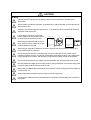
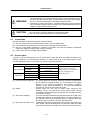
The safety precautions in this instruction manual are ranked as "WARNING" and "CAUTION".
DANGER
WARNING
CAUTION
When there is a potential risk of fatal or serious injuries if
handling is mistaken.
When operator could be fatally or seriously injured if handling
is mistaken.
When a dangerous situation may occur if handling is mistaken
leading to medium or minor injuries, or physical damage.
Note that some items described as
CAUTION may lead to major results depending on
the situation. In any case, important information that must be observed is described.
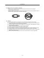
The numeric control unit is configured of the control unit, operation board, servo drive unit,
spindle drive unit, power supply unit, servomotor and spindle motor, etc.
In this section "Precautions for safety", the following items are generically called the
"servomotor".
• Servomotor
• Spindle motor
In this section "Precautions for safety", the following items are generically called the "servo
drive unit".
• Servo drive unit
• Spindle drive unit
• Power supply unit
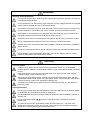
WARNING
1. Electric shock prevention
Do not open the front cover while the power is ON or during operation. Failure to observe this
could lead to electric shocks.
Do not operate the unit with the front cover removed. The high voltage terminals and charged
sections will be exposed, and can cause electric shocks.
Do not remove the front cover even when the power is OFF unless carrying out wiring work or
periodic inspections. The inside of the units is charged, and can cause electric shocks.
Wait at least 15 minutes after turning the power OFF before starting wiring, maintenance or
inspections. Failure to observe this could lead to electric shocks.
Ground the servo drive unit and servomotor with Class C (former class 3) grounding or higher.
Wiring, maintenance and inspection work must be done by a qualified technician.
Wire the servo drive unit and servomotor after installation. Failure to observe this could lead to
electric shocks.
Do not touch the switches with wet hands. Failure to observe this could lead to electric shocks.
Do not damage, apply forcible stress, place heavy items on the cables or get them caught.
Failure to observe this could lead to electric shocks.
CAUTION
1. Fire prevention
Install the servo drive units, servomotors and regenerative resistor on noncombustible
material. Direct installation on combustible material or near combustible materials could lead
to fires.
Shut off the power on the servo drive unit side if the servo drive unit fails. Fires could be
caused if a large current continues to flow.
When using a regenerative resistor, provide a sequence that shuts off the power with the
regenerative resistor's error signal. The regenerative resistor could abnormally overheat and
cause a fire due to a fault in the regenerative transistor, etc.
The battery unit could heat up, ignite or rupture if submerged in water, or if the poles are
incorrectly wired.
2. Injury prevention
Do not apply a voltage other than that specified in Instruction Manual on each terminal. Failure
to observe this item could lead to ruptures or damage, etc.
Do not mistake the terminal connections. Failure to observe this item could lead to ruptures or
damage, etc.
Do not mistake the polarity ( + , – ). Failure to observe this item could lead to ruptures or
damage, etc.
The servo drive unit's fins, regenerative resistor and servomotor, etc., may reach high
temperatures while the power is ON, and may remain hot for some time after the power is
turned OFF. Touching these parts could result in burns.
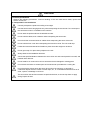
CAUTION
3. Various precautions
Observe the following precautions. Incorrect handling of the unit could lead to faults, injuries and
electric shocks, etc.
(1) Transportation and installation
Correctly transport the product according to its weight.
Use the servomotor's hanging bolts only when transporting the servomotor. Do not transport
the servomotor when it is installed on the machine.
Do not stack the products above the tolerable number.
Do not hold the cables, axis or detector when transporting the servomotor.
Do not hold the connected wires or cables when transporting the servo drive units.
Do not hold the front cover when transporting the servo drive units. The unit could drop.
Follow this Instruction Manual and install in a place where the weight can be borne.
Do not get on top of or place heavy objects on the unit.
Always observe the installation directions.
Secure the specified distance between the servo drive unit and control panel's inner wall, and
between other devices.
Do not install or run a servo drive unit or servomotor that is damaged or missing parts.
Do not block the intake or exhaust ports of the servomotor provided with a cooling fan.
Do not let foreign objects enter the servo drive units or servomotors. In particular, if
conductive objects such as screws or metal chips, etc., or combustible materials such as oil
enter, rupture or breakage could occur.
The servo drive units and servomotors are precision devices, so do not drop them or apply
strong impacts to them.
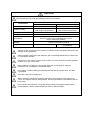
CAUTION
Store and use the units under the following environment conditions.
Environment
Ambient temperature
Ambient humidity
Storage temperature
Storage humidity
Atmosphere
Altitude
Vibration
Conditions
Servo drive unit
Servomotor
0°C to +55°C (with no freezing)
0°C to +40°C (with no freezing)
90%RH or less
80% RH or less
(with no dew condensation)
(with no dew condensation)
-15°C to +70°C
90%RH or less (with no dew condensation)
Indoors (where unit is not subject to direct sunlight),
with no corrosive gas, combustible gas, oil mist,
dust or conductive particles
1,000m or less above sea level
To follow each unit and motor
4.9m/s2 (0.5G) or less
specifications
Securely fix the servomotor to the machine. Insufficient fixing could lead to the servomotor
slipping off during operation.
Always install the servomotor with reduction gear in the designated direction. Failure to do
so could lead to oil leaks.
Structure the rotary sections of the motor so that it can never be touched during operation.
Install a cover, etc., on the shaft.
When installing a coupling to a servomotor shaft end, do not apply an impact by
hammering, etc. The detector could be damaged.
Do not apply a load exceeding the tolerable load onto the servomotor shaft. The shaft
could break.
Store the motor in the package box.
When inserting the shaft into the built-in IPM motor, do not heat the rotor higher than
130°C. The magnet could be demagnetized, and the specifications characteristics will not
be ensured.
If the unit has been stored for a long time, always check the operation before starting
actual operation. Please contact the Service Center or Service Station.
CAUTION
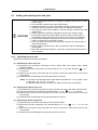
(2) Wiring
Correctly and securely perform the wiring. Failure to do so could lead to runaway of the
servomotor.
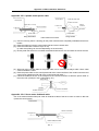
Do not install a condensing capacitor, surge absorber or radio noise filter on the output side of
the servo drive unit.
Correctly connect the output side (terminals U, V, W). Failure to do so could lead to abnormal
operation of the servomotor.
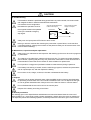
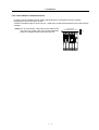
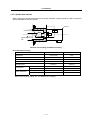
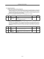
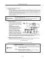
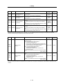
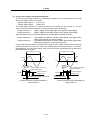
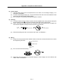
Do not directly connect a commercial
power supply to the servomotor. Failure
to observe this could result in a fault.
When using an inductive load such as a
relay, always connect a diode as a noise
measure parallel to the load.
Servodrive unit
Servodrive unit
COM
(24VDC)
Control output
signal
COM
(24VDC)
RA
Control output
signal
RA
When using a capacitance load such as a lamp, always connect a protective resistor as a
noise measure serial to the load.
Do not reverse the direction of a diode which connect to a DC relay for the control output
signals to suppress a surge. Connecting it backwards could cause the drive unit to malfunction
so that signals are not output, and emergency stop and other safety circuits are inoperable.
Do not connect/disconnect the cables connected between the units while the power is ON.
Securely tighten the cable connector fixing screw or fixing mechanism. An insecure fixing could
cause the cable to fall off while the power is ON.
When using a shielded cable instructed in the connection manual, always ground the cable with
a cable clamp, etc.
Always separate the signals wires from the drive wire and power line.
Use wires and cables that have a wire diameter, heat resistance and flexibility that conforms to
the system.
CAUTION
(3) Trial operation and adjustment
Check and adjust each program and parameter before starting operation. Failure to do so could
lead to unforeseen operation of the machine.
Do not make remarkable adjustments and changes as the operation could become unstable.
(4) Usage methods
Install an external emergency stop circuit so that the operation can be stopped and power
shut off immediately.
Turn the power OFF immediately if smoke, abnormal noise or odors are generated from the
servo drive unit or servomotor.
Unqualified persons must not disassemble or repair the unit.
Never make modifications.
Reduce magnetic damage by installing a noise filter. The electronic devices used near the
servo drive unit could be affected by magnetic noise.
Use the servo drive unit, servomotor and regenerative resistor with the designated combination.
Failure to do so could lead to fires or trouble.
The brake (magnetic brake) assembled into the servomotor is for holding, and must not be used
for normal braking.
There may be cases when holding is not possible due to the magnetic brake's life or the
machine construction (when ball screw and servomotor are coupled via a timing belt, etc.).
Install a stop device to ensure safety on the machine side.
After changing the programs/parameters or after maintenance and inspection, always test the
operation before starting actual operation.
Do not enter the movable range of the machine during automatic operation. Never place body
parts near or touch the spindle during rotation.
Follow the power supply specification conditions given in the separate specifications manual for
the power (input voltage, input frequency, tolerable sudden power failure time, etc.).
Set all bits to "0" if they are indicated as not used or empty in the explanation on the bits.
Do not use the dynamic brakes except during the emergency stop. Continued use of the
dynamic brakes could result in brake damage.
If a breaker is shared by several power supply units, the breaker may not activate when a
short-circuit fault occurs in a small capacity unit. This is dangerous, so never share the
breakers.
CAUTION
(5) Troubleshooting
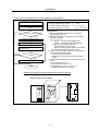
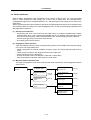
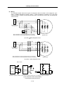
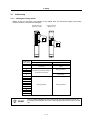
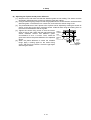
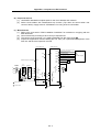
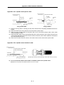
If a hazardous situation is predicted during power failure or product trouble, use a servomotor
with magnetic brakes or install an external brake mechanism.
Use a double circuit configuration
that allows the operation circuit for
the magnetic brakes to be operated
even by the external emergency
stop signal.
Shut off with the servomotor
brake control output.
Servomotor
MBR
Shut off with NC brake
control PLC output.
EMG
Magnetic
brake
24VDC
Always turn the input power OFF when an alarm occurs.
Never go near the machine after restoring the power after a power failure, as the machine
could start suddenly. (Design the machine so that personal safety can be ensured even if the
machine starts suddenly.)
(6) Maintenance, inspection and part replacement
Always carry out maintenance and inspection after backing up the servo drive unit's programs
or parameters.
The capacity of the electrolytic capacitor will drop over time. To prevent secondary disasters
due to failures, replacing this part every five years when used under a normal environment is
recommended. Contact the Service Center or Service Station for replacement.
Do not perform a megger test (insulation resistance measurement) during inspections.
If the battery low warning is issued, save the machining programs, tool data and parameters
with an input/output unit, and then replace the battery.
Do not short circuit, charge, overheat, incinerate or disassemble the battery.
(7) Disposal
Treat this unit as general industrial waste. Note that MDS Series unit with a heat dissipating
fin protruding from the back of the unit contains substitute Freon. Do not dispose of this type
of unit as general industrial waste. Always return to the Service Center or Service Station.
Do not disassemble the servo drive unit or servomotor parts.
Dispose of the battery according to local laws.
(8) General precautions
The drawings given in this Specifications and Maintenance Instruction Manual show the covers and
safety partitions, etc., removed to provide a clearer explanation. Always return the covers or partitions to
their respective places before starting operation, and always follow the instructions given in this manual.
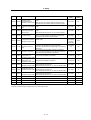
CONTENTS
1. Installation
1-1 Installation of spindle motor ................................................................................................. 1-2
1-1-1 Environmental conditions .............................................................................................. 1-2
1-1-2 Shaft characteristics ...................................................................................................... 1-2
1-2 Installation of the control unit ............................................................................................... 1-3
1-2-1 Environmental conditions .............................................................................................. 1-3
1-2-2 Installation direction and clearance ............................................................................... 1-4
1-2-3 Prevention of entering of foreign matter........................................................................ 1-4
1-2-4 Panel installation hole work drawings (Panel cut drawings)......................................... 1-5
1-2-5 Heating value................................................................................................................. 1-6
1-2-6 Heat radiation countermeasures ................................................................................... 1-7
1-3 Installing the spindle detector .............................................................................................. 1-9
1-3-1 Magnetic sensor ............................................................................................................ 1-9
1-3-2 Spindle side detector ................................................................................................... 1-11
1-4 Noise measures ................................................................................................................. 1-12
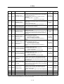
2. Wiring and Connection
2-1 Connection diagram............................................................................................................. 2-3
2-1-1 Part system connection diagram...................................................................................... 2-3
2-1-2 Detailed connection diagram ........................................................................................... 2-4
2-2 Main circuit terminal block/control circuit connector............................................................ 2-7
2-2-1 Names and applications of main circuit terminal block signals and control circuit
connectors ..................................................................................................................... 2-7
2-2-2 Connector pin assignment............................................................................................. 2-8
2-3 Drive unit connection ......................................................................................................... 2-11
2-4 Motor and detector connection .......................................................................................... 2-14
2-4-1 Connection of the spindle motor.................................................................................. 2-14
2-5 Connection of power supply .............................................................................................. 2-17
2-5-1 Power supply input connection ...................................................................................... 2-17
2-5-2 Connecting the grounding cable.................................................................................. 2-20
2-5-3 Main circuit control ......................................................................................................... 2-21
2-6 Peripheral control wiring .................................................................................................... 2-23
2-6-1 Input interface .............................................................................................................. 2-23
2-6-2 Output interface ........................................................................................................... 2-25
2-6-3 Spindle coil changeover .............................................................................................. 2-27
2-6-4 Wiring of an external emergency stop......................................................................... 2-30
3. Setup
3-1 Initial setup ........................................................................................................................... 3-2
3-1-1 Setting the rotary switch ................................................................................................ 3-2
3-1-2 Transition of LED display after power is turned ON...................................................... 3-3
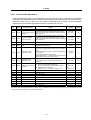
3-2 Setting the initial parameters for the spindle drive unit ....................................................... 3-4
3-2-1 Parameter setting method ............................................................................................. 3-4
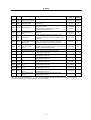
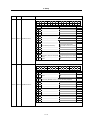
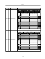
3-2-2 List of spindle parameters ............................................................................................. 3-6
3-3 Initial adjustment of the spindle PLG................................................................................. 3-26
3-3-1 Adjusting the PLG installation...................................................................................... 3-26
4. Spindle Adjustment
4-1 D/A output specifications for spindle drive unit ................................................................... 4-2
4-1-1 D/A output specifications ............................................................................................... 4-2
4-1-2 Setting the output data .................................................................................................. 4-2
4-1-3 Setting the output magnification .................................................................................... 4-3
4-2 Spindle control signal........................................................................................................... 4-5
4-2-1 Spindle control input (NC to SP) ................................................................................... 4-5
4-2-2 Spindle control output (SP to NC) ............................................................................... 4-15
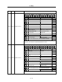
4-3 Adjustment procedures for each control ........................................................................... 4-27
4-3-1 Basic adjustments........................................................................................................ 4-27
4-3-2 Adjusting the acceleration/deceleration operation ...................................................... 4-30
4-3-3 Adjusting the orientation control .................................................................................. 4-39
4-3-4 Adjusting the multi-point indexing orientation control.................................................. 4-55
4-3-5 Adjusting S-analog high-speed tapping control .......................................................... 4-64
4-3-6 Adjusting coil changeover............................................................................................ 4-69
5. Troubleshooting
5-1 Points of caution and confirmation ...................................................................................... 5-2
5-1-1 LED display when alarm or warning occurs.................................................................. 5-3
5-2 Protective functions list of units ........................................................................................... 5-4
5-2-1 List of alarms.................................................................................................................. 5-4
5-2-2 List of warnings .............................................................................................................. 5-6
5-3 Troubleshooting ................................................................................................................... 5-7
5-3-1 Troubleshooting at power ON ....................................................................................... 5-7
5-3-2 Troubleshooting for each alarm No............................................................................... 5-8
5-3-3 Troubleshooting for each warning No. ........................................................................ 5-21
5-3-4 Troubleshooting the spindle system when there is no alarm or warning ................... 5-22
6. Maintenance
6-1 Inspections ........................................................................................................................... 6-2
6-2 Service parts ........................................................................................................................ 6-2
6-3 Adding and replacing units and parts .................................................................................. 6-3
6-3-1 Replacing the drive unit ................................................................................................. 6-3
6-3-2 Replacing the unit fan .................................................................................................... 6-4
Appendix 1. Cable and Connector Specifications
Appendix 1-1 Selection of cable .............................................................................................. A1-2
Appendix 1-1-1 Cable wire and assembly ............................................................................ A1-2
Appendix 1-2 Cable connection diagram................................................................................. A1-4
Appendix 1-3 Connector outline dimension drawings ............................................................. A1-8
Appendix 2. Compliance to EC Directives
Appendix 2-1 Compliance to EC Directives ............................................................................ A2-2
Appendix 2-1-1 European EC Directives.............................................................................. A2-2
Appendix 2-1-2 Cautions for EC Directive compliance ........................................................ A2-2
Appendix 3. EMC Installation Guidelines
Appendix 3-1 Introduction ........................................................................................................ A3-2
Appendix 3-2 EMC instructions ............................................................................................... A3-2
Appendix 3-3 EMC measures.................................................................................................. A3-3
Appendix 3-4 Measures for panel structure............................................................................. A3-3
Appendix 3-4-1 Measures for control panel unit................................................................... A3-4
Appendix 3-4-2 Measures for door ....................................................................................... A3-4
Appendix 3-4-3 Measures for operation board panel ........................................................... A3-5
Appendix 3-4-4 Shielding of the power supply input section................................................ A3-5
Appendix 3-5 Measures for various cables ............................................................................. A3-6
Appendix 3-5-1 Measures for wiring in panel ....................................................................... A3-6
Appendix 3-5-2 Measures for shield treatment..................................................................... A3-6
Appendix 3-5-3 Spindle motor power cable.......................................................................... A3-7
Appendix 3-5-4 Servo motor feedback cable ....................................................................... A3-7
Appendix 3-5-5 Spindle motor power cable.......................................................................... A3-8
Appendix 3-5-6 Spindle motor feedback cable..................................................................... A3-8
Appendix 3-6 EMC countermeasure parts .............................................................................. A3-9
Appendix 3-6-1 Shield clamp fitting ...................................................................................... A3-9
Appendix 3-6-2 Ferrite core ................................................................................................ A3-10
Appendix 3-6-3 Power line filter .......................................................................................... A3-11
Appendix 3-6-4 Surge protector.......................................................................................... A3-16
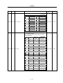
Appendix 4. Servo/spindle drive unit categories based on higher harmonic suppression
countermeasure guidelines
Appendix 4-1 Servo/spindle drive unit circuit categories based on higher harmonic suppression
countermeasure guidelines............................................................................... A4-2
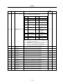
Contents for MDS-C1-SPA Series SPECIFICATIONS MANUAL (IB-1500150)
1. Introduction
1-1
Appendix 1. Outline Dimension Drawings
1-1-1
System configuration .................................................1-2
Outline dimension drawings of spindle
motor .................................................. A1-2
1-1-2
Unit outline type.........................................................1-3
Appendix 1-1-1 SJ Series ...................................................A1-2
Explanation of type..............................................1-4
Appendix 1-1-2 SJ-V Series................................................A1-5
1-2
Spindle drive system configuration .....................1-2
1-2-1
Spindle motor type.....................................................1-4
1-2-2 Spindle drive unit type ...............................................1-5
Appendix 1-1
Appendix 1-1-3 SJ-VS Series .............................................A1-15
Appendix 1-2
Unit outline dimension drawings ......... A1-17
1-2-3
Power supply unit type...............................................1-6
Appendix 1-2-1 Spindle drive unit .......................................A1-17
1-2-4
AC reactor type..........................................................1-7
Appendix 1-2-2 Power supply unit ......................................A1-21
2. Specifications
2-1 Spindle motor ......................................................2-2
Appendix 1-2-3 AC rector ...................................................A1-25
2-1-1
Specifications ............................................................2-2
2-1-2
Output characteristics ................................................2-7
2-2
Drive unit .............................................................2-12
2-2-1 Installation environment conditions ............................2-12
Appendix 2. Cable and Connector Specifications
Appendix 2-1
Appendix 2-2
Appendix 2-3
2-2-2 Spindle drive unit .......................................................2-12
2-2-3
Power supply unit ......................................................2-17
2-2-4
AC reactor .................................................................2-18
2-2-5
D/A output specifications for spindle drive unit...........2-19
2-2-6
Explanation of each part ............................................2-20
2-3
Restrictions and precautions...............................2-22
2-3-1
Layout of unit .............................................................2-22
2-3-2
Precautions for installing multiple power supply units 2-23
2-3-3
Precautions when installing multiple spindle drive
units to one power supply unit ...................................2-24
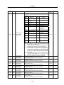
3. Characteristics
3-1
Spindle motor ......................................................3-2
Selection of cable ............................... A2-2
Appendix 2-1-1 Cable wire and assembly...........................A2-2
Cable connection diagram .................. A2-4
Connector outline dimension drawings
............................................................ A2-8
Appendix 3. Selection
Appendix 3-1
Selecting the power supply................. A3-2
Appendix 3-1-1 Selecting according to the continuous
rated capacity............................................A3-2
Appendix 3-1-2 Selection example .....................................A3-3
Appendix 4. Explanation of Large Capacity Spindle Unit
Specifications
Appendix 4-1 Explanation of large capacity spindle unit
specifications...................................... A4-2
Appendix 4-1-1 Outline .......................................................A4-2
Appendix 4-1-2 List of units ................................................A4-2
3-1-1
Environmental conditions...........................................3-2
3-1-2
Shaft characteristics ..................................................3-2
and NFB....................................................A4-2
Drive unit characteristics .....................................3-3
Appendix 4-1-4 Outline dimension drawings.......................A4-3
3-2
Appendix 4-1-3 Selection of AC reactor (B-AL), contactor
3-2-1
Environmental conditions...........................................3-3
Appendix 4-1-5 Panel cut dimension drawing .....................A4-8
3-2-2
Heating value.............................................................3-4
Appendix 4-1-6 Heating value.............................................A4-9
4. Dedicated Options
4-1
Orientation option................................................4-2
Appendix 4-1-7 Selecting the power capacity .....................A4-9
Appendix 4-1-8 Selecting the wire size ...............................A4-9
4-1-1
Magnetic sensor ........................................................4-3
Appendix 4-1-9 Drive unit connection screw size................A4-10
4-1-2
Spindle side detector (OSE-1024-3-15-68,
Appendix 4-1-10 Connecting each unit ...............................A4-10
4-2
OSE-1024-3-15-68-8)................................................4-6
Appendix 4-1-11 Restrictions..............................................A4-12
Cables and connectors .......................................4-8
Appendix 4-1-12 Parameters ..............................................A4-14
4-2-1
Cable connection diagram .........................................4-8
4-2-2
List of cables and connectors ....................................4-9
5. Peripheral Devices
5-1
Selection of wire ..................................................5-2
5-1-1 Example of wires by unit............................................5-2
5-2
Selection the AC reactor, contactor and no-fuse
breaker ...............................................................5-4
5-2-1 Standard selection.....................................................5-4
5-2-2
Selection of contactor for changing over spindle
motor drive wire.........................................................5-5
5-3
5-4
Earth leakage breaker .........................................5-6
Branch-circuit protection .....................................5-7
5-4-1
Circuit protector .........................................................5-7
5-4-2
Fuse protection..........................................................5-7
5-5
5-6
5-7
5-8
Noise filter ...........................................................5-8
Surge absorber ...................................................5-9
Speedometer and load meter..............................5-10
Cable for peripheral control .................................5-11
5-8-1
Appendix 4-1-13 Precautions..............................................A4-14
Appendix 5. Explanation of Small Capacity Spindle Drive Unit
Specifications
Appendix 5-1 Explanation of small capacity spindle
drive unit specifications....................... A5-2
Appendix 5-1-1 Outline .......................................................A5-2
Appendix 5-1-2 List of units ................................................A5-2
Appendix 5-1-3 Outline dimension drawings.......................A5-2
Appendix 5-1-4 Drive unit specifications list........................A5-4
Appendix 5-1-5 Heating value.............................................A5-5
Appendix 5-1-6 Selecting the wire size ...............................A5-5
Appendix 5-1-7 Drive unit connection screw size................A5-5
Appendix 5-1-8 Restrictions................................................A5-6
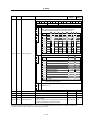
Appendix 6. Compliance to EU EC Directives
Appendix 6-1
Compliance to EC Directives .............. A6-2
Appendix 6-1-1 European EC Directives ............................A6-2
Appendix 6-1-2 Cautions for EC Directive compliance........A6-2
Cable for external emergency stop ............................5-11
(Note) This is the content for SPECIFICATION MANUAL version A. The structure of section and page number may be different
other than version B.
Contents for MDS-C1-SPA Series SPECIFICATIONS MANUAL (IB-1500150)
Appendix 7. EMC Installation Guidelines
Appendix 7-1
Appendix 7-2
Appendix 7-3
Appendix 7-4
Introduction .........................................A7-2
EMC instructions .................................A7-2
EMC measures ...................................A7-3
Measures for panel structure ..............A7-3
Appendix 7-4-1 Measures for control panel unit..................A7-3
Appendix 7-4-2 Measures for door......................................A7-4
Appendix 7-4-3 Measures for operation board panel ..........A7-4
Appendix 7-4-4 Shielding of the power supply input section
..................................................................A7-4
Appendix 7-5
Measures for various cables ...............A7-5
Appendix 7-5-1 Measures for wiring in panel ......................A7-5
Appendix 7-5-2 Measures for shield treatment....................A7-5
Appendix 7-5-3 Servomotor power cable ............................A7-6
Appendix 7-5-4 Servomotor feedback cable .......................A7-6
Appendix 7-5-5
Spindle motor power cable.........................A7-7
Appendix 7-5-6 Spindle motor feedback cable....................A7-7
Appendix 7-6
EMC countermeasure parts ................A7-8
Appendix 7-6-1 Shield clamp fitting.....................................A7-8
Appendix 7-6-2 Ferrite core ................................................A7-9
Appendix 7-6-3 Power line filter ..........................................A7-10
Appendix 7-6-4 Surge protector ..........................................A7-15
Appendix 8. Instruction Manual for Compliance with UL/c-UL
Standard
Appendix 8 Instruction Manual for Compliance with UL/c-UL
Standard.................................................A8-2
Appendix 9. Compliance with China Compulsory Product
Certification (CCC Certification) System
Appendix 9-1 Outline of China Compulsory Product
Certification System ............................A9-2
Appendix 9-2 First Catalogue of Products subject to
Compulsory Product Certification........A9-2
Appendix 9-3 Precautions for Shipping Products......A9-3
Appendix 9-4 Application for Exemption ...................A9-4
Appendix 9-5 Mitsubishi NC Product Subject to/Not Subject
to CCC Certification ............................A9-5
(Note) This is the content for SPECIFICATION MANUAL version A. The structure of section and page number may be different
other than version B.
1. Installation
1-1 Installation of spindle motor ............................................................................................................... 1-2
1-1-1 Environmental conditions ............................................................................................................ 1-2
1-1-2 Shaft characteristics .................................................................................................................... 1-2
1-2 Installation of the control unit ............................................................................................................. 1-3
1-2-1 Environmental conditions ............................................................................................................ 1-3
1-2-2 Installation direction and clearance............................................................................................. 1-4
1-2-3 Prevention of entering of foreign matter...................................................................................... 1-4
1-2-4 Panel installation hole work drawings (Panel cut drawings) ....................................................... 1-5
1-2-5 Heating value .............................................................................................................................. 1-6
1-2-6 Heat radiation countermeasures ................................................................................................. 1-7
1-3 Installing the spindle detector............................................................................................................. 1-9
1-3-1 Magnetic sensor .......................................................................................................................... 1-9
1-3-2 Spindle side detector................................................................................................................. 1-11
1-4 Noise measures ............................................................................................................................... 1-12
1-1
1. Installation
1-1 Installation of spindle motor
CAUTION
1. Do not hold the cables, axis or detector when transporting the motor. Failure to
observe this could lead to faults or injuries.
2. Securely fix the motor to the machine. Insufficient fixing could lead to the
motor deviating during operation. Failure to observe this could lead to
injuries.
3. When coupling to a servomotor shaft end, do not apply an impact by
hammering, etc. The detector could be damaged.
4. Never touch the rotary sections of the motor during operations. Install a
cover, etc., on the shaft.
5. Do not apply a load exceeding the tolerable load onto the servomotor shaft.
The shaft could break. Failure to observe this could lead to injuries.
6. Do not connect or disconnect any of the connectors while the power is ON.
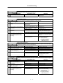
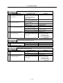
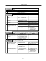
1-1-1 Environmental conditions
Environment
Conditions
Ambient temperature
Ambient humidity
Storage temperature
Storage humidity
0°C to +40°C (with no freezing)
90%RH or less (with no dew condensation)
-20°C to +65°C (with no freezing)
90%RH or less (with no dew condensation)
Indoors (Where unit is not subject to direct sunlight)
No corrosive gases, flammable gases, oil mist or dust
Operation/storage: 1000m or less above sea level
Transportation: 10000m or less above sea level
Atmosphere
Altitude
(Note) Refer to each spindle motor specifications for details on the spindle motor vibration conditions.
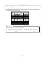
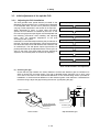
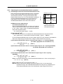
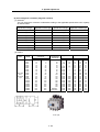
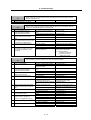
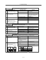
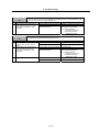
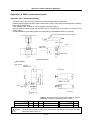
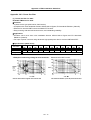
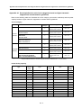
1-1-2 Shaft characteristics
There is a limit to the load that can be applied on the motor shaft. Make sure that the load applied on the
radial direction, when mounted on the machine, is below the tolerable values given below. These loads
also affect the motor output torque, so consider them when designing the machine.
Spindle motor
Tolerable radial load
SJ-V3.7-02ZM
SJ-V2.2-01, SJ-V3.7-01
SJ-V7.5-03ZM, SJ-V11-06ZM
SJ-V5.5-01, SJ-V11-08ZM
SJ-PMF01830-00
SJ-V7.5-01, SJ-V11-01
SJ-V22-06ZM, SJ-V30-02ZM, SJ-PMF03530-00
SJ-V11-09, SJ-V15-01, SJ-V15-03, SJ-V18.5-01, SJ-V18.5-03
SJ-V22-01, SJ-V22-05, SJ-V26-01, SJ-30A
SJ-22XW5
SJ-37BP
SJ-22XW8, SJ-45BP
SJ-V55-01
490 N
980 N
1470 N
1960 N
2940 N
3920 N
4900 N
5880 N
Radial load
(Note) The load point is at the one-half of the shaft length.
1-2
1. Installation
1-2 Installation of the control unit
CAUTION
1. Install the unit on noncombustible material. Direct installation on
combustible material or near combustible materials may lead to fires.
2. Follow the instructions in this manual and install the unit while allowing for
the unit weight.
3. Do not get on top of the units or motor, or place heavy objects on the unit.
Failure to observe this could lead to injuries.
4. Always use the unit within the designated environment conditions.
5. Do not let conductive objects such as screws or metal chips, etc., or
combustible materials such as oil enter the units.
6. Do not block the units intake and outtake ports. Doing so could lead to
failure.
7. The units and servomotor are precision devices, so do not drop them or apply
strong impacts to them.
8. Do not install or run units or servomotor that is damaged or missing parts.
9. When storing for a long time, please contact your dealer.
10. Always observe the installation directions. Failure to observe this could lead to
faults.
11. Secure the specified distance between the units and panel, or between the
units and other devices. Failure to observe this could lead to faults.
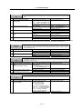
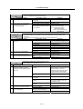
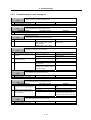
1-2-1 Environmental conditions
Environment
Ambient temperature
Conditions
0°C to +55°C (with no freezing)
Ambient humidity
90%RH or less (with no dew condensation)
Storage temperature
-15°C to +70°C (with no freezing)
Storage humidity
90%RH or less (with no dew condensation)
Atmosphere
Altitude
Indoors (no direct sunlight);
no corrosive gases, inflammable gases, oil mist, dust or conductive particles
Operation/storage: 1000m or less above sea level
Transportation: 10000m or less above sea level
2
Vibration
Operation/storage: 4.9m/s (0.5G) or less
2
Transportation: 49m/s (5G) or less
(Note) When installing the machine at 1,000m or more above sea level, the heat dissipation characteristics will drop as the
altitude increases. The upper limit of the ambient temperature drops 1°C with every 100m increase in altitude. (The
ambient temperature at an altitude of 2,000m is between 0 and 45°C.)
1-3
1. Installation
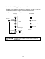
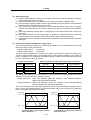
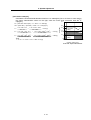
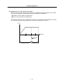
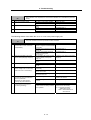
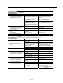
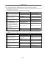
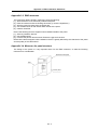
1-2-2 Installation direction and clearance
Wire each unit in consideration of the maintainability and the heat dissipation, as well as secure
sufficient space for ventilation.
75mm or more
100mm or
more
100mm or
more
10mm
or
more
10mm
or
more
100mm or
more
CAUTION
50mm
or more
100mm or
more
50mm
or more
100mm or
more
100mm or
more
The ambient temperature condition for the power supply unit or the drive units is
55°C or less. Because heat can easily accumulate in the upper portion of the
units, give sufficient consideration to heat dissipation when designing the panel.
If required, install a fan in the panel to agitate the heat in the upper portion of the
units.
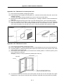
1-2-3 Prevention of entering of foreign matter
Treat the cabinet with the following items.
• Make sure that the cable inlet is dust and oil proof by using
packing, etc.
• Make sure that the external air does not enter inside by
using head radiating holes, etc.
• Close all clearances.
• Securely install door packing.
• If there is a rear cover, always apply packing.
• Oil will tend to accumulate on the top. Take special
measures such as oil-proofing to the top so that oil does
not enter the cabinet from the screw holds.
• After installing each unit, avoid machining in the periphery.
If cutting chips, etc., stick onto the electronic parts, trouble
may occur.
• When using the unit in an area with toxic gases or high
levels of dust, protect the unit with air purging (system to
blow clean air so that the panel's inner pressure is higher
than the outer pressure).
1-4
1. Installation
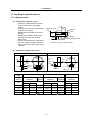
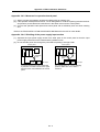
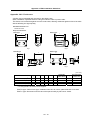
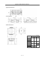
1-2-4 Panel installation hole work drawings (Panel cut drawings)
Prepare a square hole to match the unit width.
360
Square hole
342
[Unit: mm]
(Note 1)
82
2-M5 screw
Unit width: 90mm
112
2-M5 screw
(Note 1)
4-M5 screw
Unit width: 120mm
POINT
142
Unit width: 150mm
Attach packing around the square hole to provide a seal.
1-5
360
Square hole
(Note 1)
342
360
Square hole
342
60
1. Installation
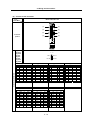
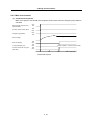
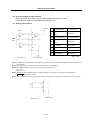
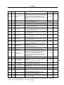
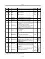
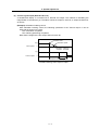
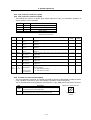
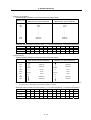
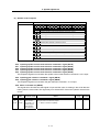
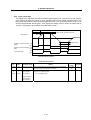
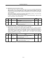
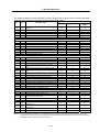
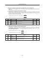
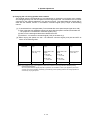
1-2-5 Heating value
Each heating value is calculated with the following values.
The values for the spindle drive unit are for a continuous rated output. The value for the power supply
unit includes the AC reactor's heating value.
Servo drive unit
Heating amount
[W]
Type
MDS-C1- Inside Outside
panel
panel
Power supply unit
Heating amount
[W]
Type
MDS-C1- Inside Outside
panel
panel
SPA- 55
SPA- 75
SPA-110
SPA-150
SPA-185
SPA-220
SPA-260
SPA-300
CV- 37
CV- 55
CV- 75
CV-110
CV-150
CV-185
CV-220
CV-260
CV-300
21
23
25
26
29
33
35
40
46
34
42
55
99
126
162
175
220
274
CV-370
54
346
31
35
41
48
62
65
80
98
76
102
140
187
280
301
403
522
(Example 1)
When using MDS-C1-CV-185, MDS-C1-SPA[]-185[]
Total heating value = (33+162) + (62+280)
= 537 [W]
Heating value in panel = (33) + (62)
= 95 [W]
1-6
1. Installation
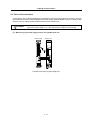
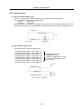
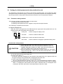
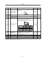
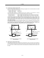
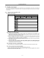
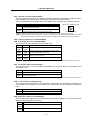
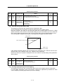
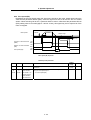
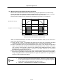
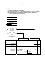
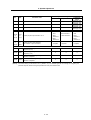
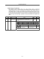
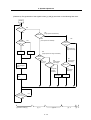
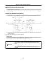
1-2-6 Heat radiation countermeasures
In order to secure reliability and life, design the temperature in the panel so that the ambient
temperature of each unit is 55°C or less.
If heat accumulates at the top of the unit, etc., install a fan so that the temperature in the panel remains
constant.
(Note) Due to the structure, heat easily accumulates at the
top of the unit. Install a fan in the power distribution
panel to circulate the heat at the top of the unit.
1-7
(Inside panel)
Wind speed 2m/s or more
Fan
1. Installation
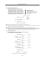
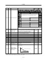
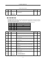
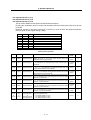
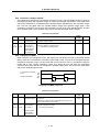
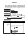
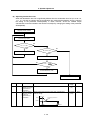
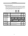
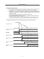
Please refer to following method for heat radiation countermeasures.
Calculate total heat radiation of each
mounted unit (W)
Calculate cabinet’s cooling capacity
(W1)
W ≤ W1
Comparison of W and W1
W>W1
Selection of heat exchanger
Mounting design
Collection of internal temperature rise
distribution data
Evaluation
∆T>10°C
Improvements
Completion
<Supplement>
1) Refer to Specifications Manual, etc. for the heat
generated by each unit.
2) Enclosed cabinet (thin steel plate) cooling capacity
calculation equation
W1 = U × A × ∆T
U: 6W/m2 × °C (with internal agitating fan)
4W/m2 × °C (without internal agitating fan)
A: Effective heat radiation area (m2)
(Heat dissipation area in panel)
Sections contacting other objects are excluded.
∆T: Internal temperature rise value (10°C)
3) Points of caution for heat radiation countermeasures
when designing mounting state
• Layout of convection in panel
• Collect hot air at suction port in heat exchanger
cabinet.
4) Understanding the temperature rise distribution in the
panel
∆T (average value) ≤ 10°C
∆Tmax (maximum value) ≤ 15°C
R (inconsistency) = (∆Tmax – ∆Tmin) ≤ 6°C
(Evaluate existence of heat spots)
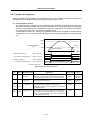
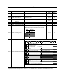
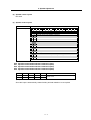
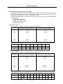
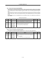
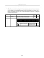
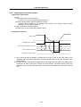
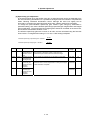
Examples of mounting and temperature measurement positions (reference)
z Measurement position (example)
Relay, etc
Heat
exchanger
∆T≤10°C
<Hypothetical conditions>
(1) Average temperature in cabinet : T ≤ 55°C
(2) Cabinet peripheral temperature : Ta ≤ 0°C to 45°C
(3) Internal temperature rise value
:
∆T =T–Tamax= 10°C
Unit
1-8
Flow of air
Flow of air
1. Installation
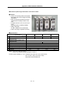
1-3 Installing the spindle detector
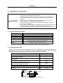
1-3-1 Magnetic sensor
(1) Installing the magnetic sensor
• Tolerance to shaft dimension should
be "h6" on the part for installing a
magnet.
• 2-øG hole can be used for positioning
of spindle and magnet.
• Magnet shall be installed as shown to
the right.
• Misalignment between sensor head
and magnetic center line shall be
within ±2mm.
• There is an NS indication on the side of
the cover. Install so that the reference
notch on the sensor head comes to the
case side.
Reference notch
Spindle
Case
G hole
Cover
h6
Gap
Spindle damping screw
Reference drawing for magnet installation
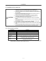
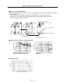
(2) Gap between magnet and sensor
Circumference installation
Horizontal installation
Direction of
rotation
Spindle
Reference
hole
Reference
notch
R
Face A
Magnet
Face A
Reference
hole
Reference
notch
Min. gap
Magnet
model
S
Circumference
installation
R (Radius)
mm
Max. value Min. value
Face B
S
N
Gap
Max. gap
Mounting plate
Magnet
Circumference
installation
Gap mm
N
Reference
hole
Reference
notch
BKO-C1730H06
Horizontal
installation
R
Face B
BKO-C1810H03
Installation
direction
Direction of
rotation
Spindle
BKO-C1730H09
Horizontal
installation
Gap mm
Circumference
installation
Gap mm
Max. value Min. value
Max. value Min. value
40
11.5±0.5
2.7±0.5
6.0±0.5
10.0±0.5
1.22±0.5
5.0±0.5
6.25±0.5
3.30±0.5
50
9.5±0.5
2.8±0.5
6.0±0.5
8.0±0.5
1.31±0.5
5.0±0.5
6.00±0.5
3.70±0.5
60
8.5±0.5
3.0±0.5
6.0±0.5
7.0±0.5
1.50±0.5
5.0±0.5
70
8.0±0.5
3.4±0.5
7.0±0.5
2.38±0.5
1-9
5.75±0.5
3.85±0.5
5.50±0.5
3.87±0.5
1. Installation
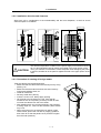
(3) Magnet and sensor installation directions
• Install so that the magnet's reference hole and sensor's reference notch are aligned.
(Standard/high-speed standards)
• Install so that the magnet's N pole comes to the left side when the sensor's reference notch is
faced downward. (High-speed compact/high-speed ring)
N
Sensor
S
S
Magnet
|
Reference notch
Sensor
N
Magnet
|
Reference notch
(4) Cautions
[1] Do not apply impacts on the magnet. Do not install strong magnets near the magnet.
[2] Sufficiently clean the surrounding area so that iron chips and cutting chips do not adhere to the
magnet. Demagnetize the round disk before installing.
[3] Securely install the magnet onto the spindle with an M4 screw. Take measures to prevent
screw loosening as required.
[4] Balance the entire spindle rotation with the magnet installed.
[5] Install a magnet that matches the spindle's rotation speed.
[6] When installing the magnet onto a rotating body's plane, set the speed to 6,000r/min or less.
[7] Install so that the center line at the end of the head matches the center of the magnet.
[8] The BKO-C1730 is not an oil-proof product. Make sure that oil does not come in contact with
BNO-C1730 or BKO-C1810.
[9] When connecting to the spindle drive unit, wire so that the effect of noise is suppressed.
1 - 10
1. Installation
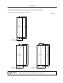
1-3-2 Spindle side detector
When coupling the spindle side detector with spindle, a flexible coupling should be used to couple the
spindle side detector with the spindle.
Detector
Flexible coupling
0.02
0.02
Opposite detector shaft
side
Detector and coupling installation accuracy
Recommended coupling
Recommendation 1
Recommendation 2
Tokushu Seiko
Eagle
Model M1
FCS38A
1374Hz
3515Hz
0.8×10⁻³°
1.2×10⁻³°
20000r/min
10000r/min
0.7mm
0.16mm
1.5°
1.5°
Max. length
74.5mm
33mm
Max. diameter
ø57mm
ø38mm
Manufacturer
Model
Resonance frequency
Position detection error
Tolerable speed
Mis-alignment
Core deviation
Angle displacement
Outline dimensions
Refer to the coupling catalog, etc., for details on the coupling.
1 - 11
1. Installation
1-4 Noise measures
Noise includes "propagation noise" generated from the power supply or relay, etc., and propagated
along a cable causing the power supply unit or drive unit to malfunction, and "radiated noise"
propagated through air from a peripheral device, etc., and causing the power supply unit or drive unit to
malfunction.
Always implement these noise measures to prevent the peripheral devices and unit from malfunctioning.
The measures differ according to the noise propagation path, so refer to the following explanation and
take appropriate measures.
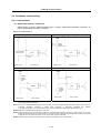
(1) General noise measures
• Avoid laying the drive unit's power line and signal wire in a parallel or bundled state. Always
separate these wires. Use a twisted pair shielded wire for the detector cable and signal wires
such as the communication cable connected with the NC, and accurately ground the devices.
• Use one-point grounding for the drive unit and motor.
• Accurately ground the AC reactor.
(2) Propagation noise measures
Take the following measures when noise generating devices are installed and the power supply
unit or drive unit could malfunction.
• Install a surge killer on devices (magnetic contacts, relays, etc.) which generate high levels of
noise.
• Install a power line filter in the stage before the power supply unit.
• Install a ferrite core on the signal wire.
• Ground the shield of the servo detector's cable with a cable clamp.
• Wire the spindle PLG detector cable away from other wires.
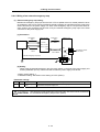
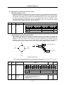
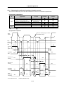
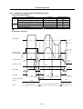
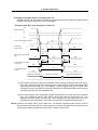
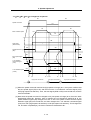
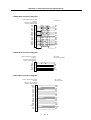
(3) Measures against radiated noise
The types of propagation paths of the noise and the noise measures for each propagation path are
shown below.
Noise generated from
drive unit
Airborne
propagation noise
Noise directly radiated
from drive unit
Path [1]
Magnetic induction
noise
Path [4]
and [5]
Noise radiated from
power line
Path [2]
Static induction
noise
Path [6]
Noise radiated from
spindle motor
Path [3]
Noise propagated over
power line
Path [7]
Noise lead in from
grounding wire by
leakage current
Path [8]
Cable propagation
noise
1 - 12
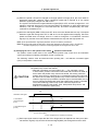
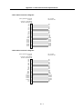
1. Installation
[5]
[7]
[7]
[2]
[2]
[1]
Instrument
Drive
unit
Receiver
[6]
[3]
Sensor
power
supply
[4]
[8]
Sensor
Spindle motor
M
Generated noise of drive system
Noise propagation path
[1] [2] [3]
[4] [5] [6]
[7]
[8]
Measures
When devices such as instrument, receiver or sensor, which handle minute signals and are easily
affected by noise, or the signal wire of these devices, are stored in the same panel as the drive
units and the wiring is close, the device could malfunction due to airborne propagation of the noise.
In this case, take the following measures.
(a) Install devices easily affected as far away from the drive units as possible.
(b) Lay devices easily affected as far away from the signal wire of the drive unit as possible.
(c) Avoid laying the signal wire and power line in a parallel or bundled state.
(d) Insert a line noise filter on the input/output wire or a radio filter on the input to suppress the
noise radiated from the wires.
(e) Use a shield wire for the signal wire and power line, or place in separate metal ducts.
If the signal wire is laid in parallel to the power line, or if it is bundled with the power line, the noise
could be propagated to the signal wire and cause malfunction because of the magnetic induction
noise or static induction noise. In this case, take the following measures.
(a) Install devices easily affected as far away from the drive unit as possible.
(b) Lay devices easily affected as far away from the signal wire of the drive unit as possible.
(c) Avoid laying the signal wire and power line in a parallel or bundled state.
(d) Use a shield wire for the signal wire and power line, or place in separate metal ducts.
If the power supply for the peripheral devices is connected to the power supply in the same system
as the drive units, the noise generated from the power supply unit could back flow over the power
line and cause the devices to malfunction. In this case, take the following measures.
(a) Install a radio filter on the power supply unit's power line.
(b) Install a power filter on the power supply unit's power line.
If a closed loop is created by the peripheral device and drive unit's grounding wire, a leakage
current could flow and cause the device to malfunction.
In this case, change the device grounding methods and the grounding place.
1 - 13
2. Wiring and Connection
2-1 Connection diagram ........................................................................................................................... 2-3
2-1-1 Part system connection diagram.................................................................................................. 2-3
2-1-2 Detailed connection diagram........................................................................................................ 2-4
2-2 Main circuit terminal block/control circuit connector .......................................................................... 2-7
2-2-1 Names and applications of main circuit terminal block signals and control circuit connectors .. 2-7
2-2-2 Connector pin assignment .......................................................................................................... 2-8
2-3 Drive unit connection........................................................................................................................ 2-11
2-4 Motor and detector connection ........................................................................................................ 2-14
2-4-1 Connection of the spindle motor ............................................................................................... 2-14
2-5 Connection of power supply............................................................................................................. 2-17
2-5-1 Power supply input connection ................................................................................................. 2-17
2-5-2 Connecting the grounding cable ............................................................................................... 2-20
2-5-3 Main circuit control .................................................................................................................... 2-21
2-6 Peripheral control wiring................................................................................................................... 2-23
2-6-1 Input interface............................................................................................................................ 2-23
2-6-2 Output interface......................................................................................................................... 2-25
2-6-3 Spindle coil changeover ............................................................................................................ 2-27
2-6-4 Wiring of an external emergency stop....................................................................................... 2-30
2-1
2. Wiring and Connection
DANGER
1. Wiring work must be done by a qualified technician.
2. Wait at least 15 minutes after turning the power OFF and check the voltage
with a tester, etc., before starting wiring. Failure to observe this could lead to
electric shocks.
3. Securely ground the drive units and spindle motor.
4. Wire the drive units and spindle motor after installation. Failure to observe this
could lead to electric shocks.
5. Do not damage, apply forcible stress, place heavy items on the cables or get
them caught. Failure to observe this could lead to electric shocks.
6. Always insulate the power terminal connection section. Failure to observe
this could lead to electric shocks.
1. Correctly and securely perform the wiring. Failure to do so could result in
runaway of the spindle motor or injury.
2. Do not mistake the terminal connections.
Failure to observe this item could lead to ruptures or damage, etc.
3. Do not mistake the polarity ( + , - ). Failure to observe this item could lead to
ruptures or damage, etc.
4. Do not mistake the direction of the diodes for the surge absorption installed
on the DC relay for the general-purpose output and contactor (magnetic
contactor) control. The signal might not be output when a failure occurs.
Servodrive unit
Servodrive unit
COM
(24VDC)
COM
(24VDC)
Control output
signal
RA
Control output
signal
RA
CAUTION
5. Electronic devices used near the drive units may receive magnetic
obstruction. Reduce the effect of magnetic obstacles by installing a noise
filter, etc.
6. Do not install a phase advancing capacitor, surge absorber or radio noise
filter on the power line (U, V, W) of the spindle motor.
7. Do not modify this unit.
8. The half-pitch connector (CN10, etc.) on the front of the drive units have the
same shape. If the connectors are connected incorrectly, faults could occur.
Make sure that the connection is correct.
9. When grounding the motor, connect to the protective grounding terminal on
the drive units, and ground from the other protective grounding terminal.
(Use one-point grounding) Do not separately ground the connected motor
and drive unit as noise could be generated.
2-2
2. Wiring and Connection
2-1 Connection diagram
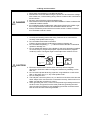
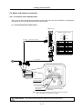
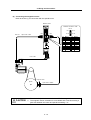
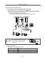
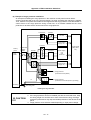
2-1-1 Part system connection diagram
Power supply unit
Spindle drive unit
General purpose, general-purpose output
CN10
CN4
CN11
CN4
CN12
CN9
CN9A
Orientation position command,
General-purpose output
Digital speed command,
general-purpose • error output
Speed • load meter, serial I/F
S-analog speed command, pulse feedback
CN8A
External emergency stop input
Spindle side detector
CN23
CN6
CN5
AC
reactor
No-fuse
breaker
Contactor
U
R
L1
S
L2
T
L3
TE1
MC
V
Spindle
motor
W
TE1
TE2
Ground
Breaker
ENC
L+
L+
L-
L-
PLG
TE2
MC1
L11
L21
TE3
L11
TE3
L21
: Main circuit
: Control circuit
Ground
Ground
(Note 1) The connection method will differ according to the used motor.
(Note 2) The main circuit ( ) and control circuit ({) are safely separated.
2-3
NC
PC
DIO
Meter
Personal computer
2. Wiring and Connection
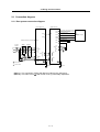
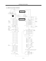
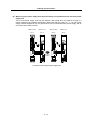
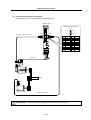
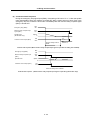
2-1-2 Detailed connection diagram
(1) With no orientation / When using motor built-in encoder orientation
B-AL Contactor
TYPE
MDS-C1-CV-□
NFB3
TYPE
MDS-C1-SPA-□
2-4
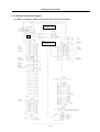
2. Wiring and Connection
(2) When using magnetic sensor orientation
B-AL
Contactor
TYPE
MDS-C1-CV-□
NFB3
TYPE
MDS-C1-SPA-□
2-5
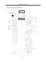
2. Wiring and Connection
(3) When using encoder orientation
B-AL Contactor
TYPE
MDS-C1-CV-□
NFB3
TYPE
MDS-C1-SPA-□
2-6
2. Wiring and Connection
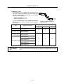
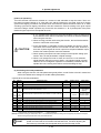
2-2 Main circuit terminal block/control circuit connector
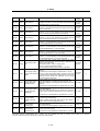
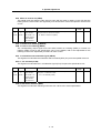
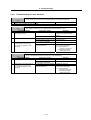
2-2-1 Names and applications of main circuit terminal block signals and control circuit
connectors
The following table shows the details for each terminal block signal.
Name
Signal name
L1 . L2 . L3
Main circuit power
supply
Control circuit power
supply
Description
MC1
Contactor control
U.V.W
Motor output
(Single-axis unit)
Main circuit power supply input terminal
Connect a 3-phase 200VAC/200 to 230VAC, 50/60Hz power supply.
Control circuit power supply input terminal
Connect a single-phase 200VAC/200 to 230VAC, 50/60Hz power supply.
Contactor control terminal
The MC1 terminal has the same phase as L21. Connect to a different phase than the
phase connected to L21.
Servo/spindle motor power output terminal
The servo/spindle motor power terminal (U, V, W) is connected.
Motor output
(Dual-axis unit)
Servo motor power output terminal (L-axis/M-axis)
The servo/spindle motor power terminal (U, V, W) is connected.
L11 L21
LU . LV . LW
MU . MV . MW
Protective grounding Grounding terminal
(PE)
The servomotor/spindle motor grounding terminal is connected and grounded.
CAUTION
1. Always use one AC reactor per power supply unit. Failure to observe this
could lead to unit damage.
2. When sharing a breaker for several power supply units, of a short-circuit
fault occurs in a small capacity unit, the breaker could trip. This can be
hazardous, so do not share the breaker.
3. Be sure to use the breaker of proper capacity for each power supply unit.
2-7
2. Wiring and Connection
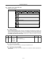
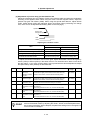
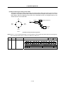
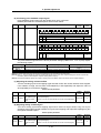
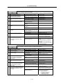
2-2-2 Connector pin assignment
Do not apply a voltage other than that specified in Instruction Manual on each
terminal. Failure to observe this item could lead to rupture or damage, etc.
CAUTION
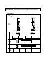
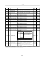
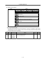
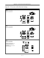
(1) Main circuit terminal block
Power supply unit
Unit
MDS-C1-CV-37 to 75
MDS-C1-CV-110 to 370
Terminal
Terminal
position
[2]
[2]
[3]
[3]
[1]
[1]
[4]
[4]
U V W
U V W
Terminal specification/Pin assignment
[1]
TE1
[2]
TE2
[3]
TE3
[4]
Compatible unit
CV-37 to 75
Compatible unit
Screw size
Tightening torque
M4
1.6Nm
Screw size
Tightening torque
CV-110 to 185 CV-220 to 370
M5
3.37Nm
L+
Compatible unit
CV-37 to 370
L-
Screw size
Tightening torque
M6
5.0Nm
Compatible unit
CV-37 to 75
CV-110 to 370
Screw size
Tightening torque
M4
2.0Nm
M4
1.6m
L11
L21
MC1
Compatible unit
CV-37 to 75
Compatible unit
Screw size
Tightening torque
M4
2.0Nm
Screw size
Tightening torque
2-8
M8
13.2Nm
CV-110 to 185 CV-220 to 370
M5
3.37Nm
M8
13.2Nm
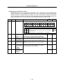
2. Wiring and Connection
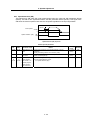
Spindle drive unit
Unit
MDS-C1-SPA-55 to 300
Terminal
Terminal
position
[2]
[3]
[1]
[4]
U V W
Terminal specification/Pin assignment
[1]
[2]
[3]
[4]
TE1
MDS-C1-SPA-
55 to 185
220 to 300
Screw size
Tightening torque
M5
3.2Nm
M8
13.2Nm
L+
Compatible unit
All capacity
L-
Screw size
Tightening torque
M6
5.0Nm
Compatible unit
All capacity
Screw size
Tightening torque
M4
2.0Nm
TE2
TE3
L11
L21
The PE screw size is the same as TE1.
2-9
2. Wiring and Connection
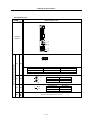
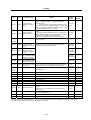
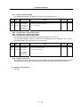
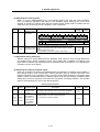
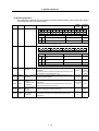
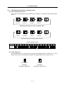
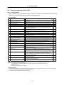
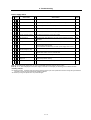
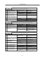
(2) Control circuit connector
Unit
MDS-C1-SPA-55 to 300
Terminal
Connector
position
[1]
[2]
[3]
[4]
[5]
[6]
[7]
[9]
[1] CN11
[2] CN12
[3] CN9A
[4] CN4
[5] CN5
[6] CN6
[7] CN10
[8] CN8A
Pin No.
[5] CN5
Connector specifications
GND
RD
MOH
SD
P15
PA
PB
PZ
P24
-
11
12
13
14
15
16
17
18
19
20
GND
RD*
RG
SD*
N15
RA
RB
-
11
12
13
14
15
16
17
18
19
20
No.20
[9] CN8A
GND
MA
MB
MZ
P15B
MSA
LSA
P5
11
12
13
14
15
16
17
18
19
20
GND
MA*
MB*
MZ*
GND
MSC
LSC
P5
P5
SRN
IN1
IN3
IN5
IN7
IN9
+24V
IN11
CES1
OUT6C
1H
3H
5H
7H
9H
11H
OUT1
OUT3
OUT5
OUT6
11
12
13
14
15
16
17
18
19
20
GND
SYA
SYB
SYZ
SES
RP
SE1
SE2
-
11
12
13
14
15
16
17
18
19
20
GND
SYA*
SYB*
SYZ*
ORS
OR3
OR2
OR1
-
[2] CN12
Pin assignment
1
2
3
4
5
6
7
8
9
10
[3] CN9A
Pin assignment
1
2
3
4
5
6
7
8
9
10
[1] CN11
Pin assignment
REDY
SRI
IN2
IN4
IN6
IN8
IN10
IN12
RG
No.10
Pin assignment
1
2
3
4
5
6
7
8
9
10
[7] CN10
1
2
3
4
5
6
7
8
9
10
No.11
[6] CN6
Pin assignment
1
2
3
4
5
6
7
8
9
10
No.1
2H
4H
6H
8H
10H
12H
OUT2
OUT4
CES3
OUT7
2 - 10
Pin assignment
1
2
3
4
5
6
7
8
9
10
R1
R3
R5
R7
R9
R11
OUT1C
OUT3C
OUT5C
FA
11
12
13
14
15
16
17
18
19
20
R2
R4
R6
R8
R10
R12
OUT2C
OUT4C
CES2
FC
Pin assignment
1
2
3
4
5
6
7
8
9
10
GND
DR
CLK
P5
RX
IU
OUT8
SM0
-
11
12
13
14
15
16
17
18
19
20
GND
DX
FSX
TX
IV
P5
LM0
-
2. Wiring and Connection
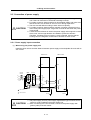
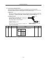
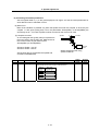
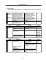
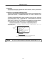
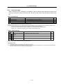
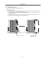
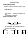
2-3 Drive unit connection
In this section, the connection between the spindle drive unit and power supply unit is shown. There is
space between units in the following diagram to make clearly understandable. However, actually, install
the drive units so that the space between the drive units is within 3cm.
POINT
Even if two or more spindle drive units are used, keep the setting of the spindle
drive unit’s rotary switch to “0”. This switch has no relation to the axis No.
(1) When using one power supply unit for one spindle drive unit
MDS-C1-SPA
MDS-C1-CV
CN4
CN4
Connection when using one power supply unit
2 - 11
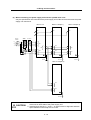
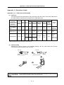
2. Wiring and Connection
(2) When using two power supply units and connecting one spindle drive unit with each power
supply unit
Two or more power supply units may be required if the spindle drive unit capacity is large in a
machine applying two spindles specification. Make sure that the powers (L+, L-) of both power
supply units are supplied to only one spindle drive unit connected with each power supply, and do
not connect each other's powers.
MDS-C1-SPA
MDS-C1-CV
MDS-C1-SPA
MDS-C1-CV
(No.1)
(No.1)
(No.2)
(No.2)
CN4
CN4
CN4
CN4
Power
cannot be
supplied
Connections when using two power supply units
2 - 12
2. Wiring and Connection
(3) When connecting two or more spindle drive units with one power supply unit
Connect units according to the following cautions.
MDS-C1-SPA
MDS-C1-CV
(No.1)
MDS-C1-SPA
MDS-C1-SPA
(No.2)
(No.3)
CN4
CN4
CN4
CN9
Connections when sharing one power supply
(Note 1) Connecting power supply unit and spindle drive unit.
Connect C1-CV CN4 and C1-SPA (No. 1) CN4 to C1-CV CN9 and C1-SPA (No.2) CN4. If
C1-SPA is connected with three or more axes, leave CN4 for C1-SPA (No. 3) and
following open.
Note that the C1-CV can be controlled (READY ON/OFF, alarm display, etc.) only by the
spindle drive unit connected to C1-CV CN4.
(Note 2) Make sure that the machine ready complete input turns ON and OFF simultaneously for all
the spindle drive units. Do not allow the signal to turn ON and OFF for only one spindle
drive unit.
(Note 3) When turning the machine ready complete input OFF during an emergency stop, always
have all the spindle drive units output the zero speed signal before turning the signal OFF.
(Note 4) If an alarm occurs in one of the spindle drive units, turn OFF the machine ready complete
input OFF for all the spindle drive units.
(Note 5) When connecting three or more spindle drive units, install the large-capacity spindle drive
units on both sides of the power supply unit.
2 - 13
2. Wiring and Connection
2-4 Motor and detector connection
2-4-1 Connection of the spindle motor
Refer to each motor specifications for details on the motor side connection destination, specifications
and outline, and for the spindle PLG detector specifications.
(1) Connecting the motor built-in PLG
MDS-C1-SPA
Detector connector : CN5
Pin No.
CN5
Max. 30m
Option cable : CNP5
No.1
No.11
No.10
No.20
Pin
Name
1
LG
2
3
MOH
4
5 P15(+15V)
PA
6
7
PB
8
PZ
9
10
Pin
Name
11
12
13
RG
14
15 N15(-15V)
16
RA
17
RB
18
19
20
Power cable
U V W
BU BV BW
U VW
Spindle motor
Cooling fan terminal
block (BU,BV,BW)
Grounding terminal
Motor power terminal
block (U,V,W)
Example for 3-phase cooling fan
power supply
(Note) Either a single-phase or 3-phase power supply is used for the cooling fan.
Refer to the Spindle Motor Specifications for details.
CAUTION
The shield of spindle detector cable is not FG. Do not ground.
2 - 14
2. Wiring and Connection
(2) Connecting the magnetic sensor
Refer to section (1) for connection with the spindle motor.
MDS-C1-SPA
Detector connector : CN6
Pin No.
Max. 30m
Option cable : CNP5
CN5
CN6
No.1
No.11
No.10
No.20
Pin
Name
1
2
3
4
5 P15(+15V)
6
MAG
7
LS
8
9
10
Pin
11
12
13
14
15
16
17
18
19
20
Name
LG
MAGR
LSR
Power cable
U V W
U VW
Spindle motor
Magnetic sensor
Spindle
Option cable : CNP6M
CAUTION
1. The shield of spindle detector cable is not FG. Do not ground.
2. The magnetic sensor orientation is not available with a machine having a
gear ratio between the motor and spindle exceeding 1:31.
2 - 15
2. Wiring and Connection
(3) Connecting the spindle side detector
Refer to section (1) for connection with the spindle motor.
MDS-C1-SPA
Detector connector : CN6
Pin No.
CN5
Max. 30m
CN6
No.1
No.11
No.10
No.20
Option cable : CNP5
Pin
1
2
3
4
5
6
7
8
9
10
Name
LG
MA
MB
MZ
P5(+5V)
Power cable
U V W
U VW
Spindle motor
Spindle
Spindle side detector
Option cable: CNP6A
CAUTION
The shield of spindle detector cable is not FG. Do not ground.
2 - 16
Pin
11
12
13
14
15
16
17
18
19
20
Name
LG
MA*
MB*
MZ*
LG
P5(+5V)
P5(+5V)
2. Wiring and Connection
2-5 Connection of power supply
CAUTION
1. Make sure that the power supply voltage is within the specified range of each
unit. Failure to observe this could lead to damage or faults.
2. For safety purposes, always install a No-fuse breaker (NFB), and make sure
that the circuit is cut off when an error occurs or during inspections.
3. The wire size will differ according to each drive unit capacity.
4. For safety purposes, always install a magnetic contactor (contactor) on the
main circuit power supply input. Large rush currents will flow when the power
is turned ON.
5. A semiconductor element is used in the power supply unit's magnetic contact
drive circuit, and a surge absorber is installed to protect the element.
Therefore, a leakage current of approx. 15mA is passed. Confirm that the
exciting coil in the magnetic contact will not function at 15mA or less.
2-5-1 Power supply input connection
(1) When using one power supply unit
Install the drive units so that the distance between power supply unit and spindle drive unit will be
3cm or less.
MDS-C1-CV
CN4
CN4
AC
reactor
No-fuse
breaker
Contactor
R
L1
S
L2
T
L3
TE1
TE2
Ground
Breaker
MDS-C1-SPA
MC
L+
L+
L-
L-
TE2
MC1
L11
TE3
L11
L21
TE3
L21
: Main circuit
: Control circuit
Ground
CAUTION
Ground
1. The power supply unit is a power supply regenerative type converter; an AC
reactor is surely installed in the power supply line.
2. When connecting to the TE3 terminal, connect to the power supply side
(primary side) of the AC reactor.
2 - 17
2. Wiring and Connection
(2) When using two power supply units, and connecting one spindle drive unit with each power
supply unit
Install a no-fuse breaker and a contactor for each of the power supply units.
Install the drive units so that the distance between power supply unit and spindle drive unit will be
3cm or less. The installation distance between No.1 and No.2.is not particularly specified.
MDS-C1-CV(No.1)
CN4
CN4
AC
reactor
No-fuse
breaker
Contactor
R
L1
S
L2
T
L3
TE1
TE2
Ground
Breaker
MDS-C1-SPA(No.1)
MC
L+
L+
L-
L-
TE2
MC1
TE3
L11
L11
L21
TE3
L21
Ground
MDS-C1-CV(No.2)
AC
reactor
Contactor
R
L1
S
L2
T
L3
TE1
TE2
Ground
Breaker
MDS-C1-SPA(No.2)
CN4
CN4
No-fuse
breaker
Ground
MC
L+
L+
L-
L-
TE2
MC1
L11
TE3
L11
L21
TE3
L21
: Main circuit
: Control circuit
Ground
CAUTION
Ground
An AC reactor and breaker are required for each power supply unit.
2 - 18
2. Wiring and Connection
(3) When connecting one power supply unit with two spindle drive units
Only the spindle drive unit connected to the power supply unit's CN4 connector becomes the power
supply unit control axis.
MDS-C1-CV
MDS-C1-SPA(No.1)
CN4
CN4
MDS-C1-SPA(No.2)
CN4
CN9
No-fuse
breaker
AC
reactor
Contactor
R
L1
S
L2
T
L3
TE2
Ground
Breaker
TE1
MC
L+
L+
L-
L-
TE2
L+
L-
TE2
MC1
L11
TE3
L11
TE3
L11
TE3
L21
L21
L21
Ground
Ground
Ground
MDS-C1-SPA(No.3)
L+
TE2
L-
L11
TE3
L21
Ground
CAUTION
1. When connecting two or more spindle drive units, install the large-capacity
drive units on both sides of the power supply unit.
2. Install units so that the “L+” and “L-” of each unit are in alignment and each
space between units is kept to 3cm or less.
2 - 19
2. Wiring and Connection
2-5-2 Connecting the grounding cable
(1) Connecting the protective grounding (PE) and frame ground (FG)
Each unit has a terminal or mounting hole to connect PE ( ) or FG.
Please connect an earth wire to the main ground of a cabinet or a machine frame at one point.
Ground each device according to the grounding conditions set forth by each country. (Typically, a
Y-connection neutral point ground is used in Europe.)
PE: Grounding to provide protection from electric shock, etc.
FG: Grounding to stabilize the operation of the devices, etc. (Suppress noise)
MDS-C1-SPA(No.1) MDS-C1-CV
MDS-C1-SPA(No.2)
B-AL
Grounding plate
SJ Series motor
POINT
Do not connect the grounding cable from
each unit directly to the grounding plate.
Noise from other units could result in
malfunctions.
Unit
(2) Grounding cable size
Earth wire size should follow the following table.
Type
Grounding cable size (Required grounding)
MDS-C1-CV Unit
Larger than thickness of wire connected to TE1 (L1/L2/L3). (PE)
MDS-C1-SPA[] Unit
Larger than thickness of wire connected to TE1 (U/V/W). (PE)
B-AL (AC Reactor)
5.5 mm (AWG10) or more (FG)
2
2 - 20
Grounding
plate
2. Wiring and Connection
2-5-3 Main circuit control
(1) Contactor ON sequence
Main circuit power is turned ON in the sequence shown below when an emergency stop status is
canceled.
Machine ready complete input
signal (READY)
OFF
ON
Contactor control output (MC1)
ON
OFF
Emergency stop (EMG)
OFF
ON
PN charging completed
PN bus voltage
Motor ON (GATE)
In ready ON signal (ron)
Forward run/reverse run signal
(SRN, SRI)
ON
OFF
ON
OFF
ON
OFF
Ready completion・Command input enable
0
500
Contactor ON sequence
2 - 21
1000
1500 Time (ms)
2. Wiring and Connection
(2) Contactor shutoff sequence
During the emergency stop signal input (EMG), if the setting of SP193 is "0" or "1" after the spindle
motor decelerates to stop, the contactor is turned OFF after a certain amount of time. Even in the
emergency stop, the contactor is turned OFF immediately after the machine ready complete signal
(RDY) is turned OFF.
Emergency stop (EMG)
OFF
ON
Machine ready complete input
signal (RDY)
OFF
ON
Spindle motor
(deceleration stop)
Contactor control output (MC1)
Speed
0
SP193: 2,3
ON
OFF
Same as setting value of
SP055
SP193: 0,1
Contactor OFF sequence (When machine ready complete input signal is input after the setting time of SP055)
Emergency stop (EMG)
OFF
ON
Machine ready complete input
(RDY)
OFF
ON
Spindle motor
Motor coasts to stop.
Speed
0
Contactor control output (MC1)
ON
OFF
Same as setting value of SP055
Contactor OFF sequence
(When machine ready complete input signal is input during deceleration stop)
2 - 22
2. Wiring and Connection
2-6 Peripheral control wiring
2-6-1 Input interface
(1) Digital input interface: CN10 to 12
(Special input: 3 points, general-purpose input: 12 points, multi-points orientation command: 12
points, digital speed command: 12 points)
Select from the following.
1) Connecting with contact
2) Connecting with photo coupler
+24V
+24V
Current
capacity
5.1mA or more
Current capacity
5.1mA or more
4.7KΩ
4.7KΩ
CES
1 to 3
CES
1 to 3
NC(PC) side
NC(PC) side
Drive unit side
3) Connecting with open emitter
4) Connecting with open collector
+24V
+24V
Current
capacity
5.1mA or
more
CES 1 to 3
4.7KΩ
4.7KΩ
Current
capacity
5.1mA or
more
CES
1 to 3
NC(PC) side
Drive unit side
NC(PC) side
Drive unit side
Drive unit side
(Note 1) A +24V(±10%) power supply is required for this unit. The required maximum power supply capacity is 26W. DC stabilized
power supply must be used here.
(Note 2) Common for dedicated/general-purpose input is CES1, common for digital speed command is CES2, and common for
multi-point orientation command is CES3. Each command is electrically separated one another.
Thus, when using CES1, 2 or 3, each of them has to be connected to one of the signals (power supply, etc.).
(Note 3) Filter time constant at the input section is 5 to 15ms.
(Note 4) When running the motor on a trial basis, (when only "machine ready complete", "forward run" and "reverse run" are input
and all the other 24V I/O are not used.), external +24V power supply is exceptionally not necessary; internal +24V power
supply will do. In this case, use CN10-7 pin for +24V, CN10-10 pin for RG (24G).
(Note 5) Power supply unit's CN23 is a similar circuit; however, the resistance is not 4.7kΩ but 2kΩ.
2 - 23
2. Wiring and Connection
(2) Encoder (1024p/rev) input interface
When connecting an encoder, +5V must be supplied from the drive unit side.
Power does not need to be supplied from the NC(PC) side.
(3) Analog input interface
Analog speed
command input
+15V
1KΩ
Override input
Upper speed limit
A
VR1
Not required
setting
VR1
680Ω
VR2 Analog speed setting
B
VR2
2KΩ
Override speed setting
Lower speed limit
VR3
VR3
1KΩ
D
NC(PC) side
Not required
setting
C
A
RP (CN8A-6)
OR3 (CN8A-16)
B
SE1 (CN8A-7)
OR2 (CN8A-17)
C
SE2 (CN8A-8)
OR1 (CN8A-18)
D
SES (CN8A-5)
ORS (CN8A-15)
Input impedance of input pin B (SE1, OR2):
Approx. 10KΩ
Drive unit side
(Note 1) The figure above indicates the case of unipolar input. (Bipolar input cannot be created only with the power supply from the
drive unit side.)
(Note 2) +15V power supply is output from the input pin A (RP, OR3) via the resistance.
(Note 3) Input voltage tolerable value of the input pin B (SE1, OR2) is as follows.
SE1: ±12V
OR2: 0 to +12V
(Note 4) Make sure to use a shielded cable for the cable connecting to each input pin and provide with shield treatment.
(
represents for a shield.)
(Note 5) If there is a separate analog speed input command (or override input) power supply, connection will be as shown below.
B
C
D
NC(PC) side
Drive unit side
2 - 24
2. Wiring and Connection
2-6-2 Output interface
(1) External contact output circuit
The drive unit fault output signal FA(CN12-10) and FC(CN12-20) are the outputs.
Use the contacts with the rating indicated below.
24VDC
0.3A or less
Chattering
5ms or less
Compact relay is used. When connecting an inductive load such as relay, preferably use a DC
compact relay, and connect a flywheel diode in parallel with the coil as shown in the figure below.
FA(CN12-20)
Flywheel diode
24V
RA
FC(CN12-20)
Drive unit side
NC(PC) side
(2) Open emitter output circuit
The followings are the open emitter outputs.
General-purpose output 1: OUT1 (CN11-7)
General-purpose output 2: OUT2 (CN11-17)
General-purpose output 3: OUT3 (CN11-8)
General-purpose output 4: OUT4 (CN11-18)
General-purpose output 5: OUT5 (CN11-9)
General-purpose output 6: OUT6 (CN11-10)
General-purpose output 7: OUT7 (CN11-20)
General-purpose output 8: OUT8 (CN9A-8)
Output transistor rating
M54630P TR array
Tolerable voltage 24VDC or less
Tolerable current 50mA or less
(per 1 output)
24V
+24V(CN10-17)
OUT1 to 8
RA
RG(CN10-10)
Drive unit side
NC(PC) side
2 - 25
2. Wiring and Connection
(3) Open collector output circuit
The followings are the open collector outputs.
General-purpose output 1C: OUT1C (CN12-7)
General-purpose output 2C: OUT2C (CN12-17)
General-purpose output 3C: OUT3C (CN12-8)
General-purpose output 4C: OUT4C (CN12-18)
General-purpose output 5C: OUT5C (CN12-9)
General-purpose output 6C: OUT6C (CN10-20)
Output transistor rating
M54633P TR array
Tolerable voltage 24VDC or less
Tolerable current 50mA or less
(per 1 output)
24V
24V
+24V(CN10-17)
RA
OUT1C to 6C
RG(CN10-10)
Drive unit side
NC(PC) side
(Note 1) When using a DC relay externally, connect a flywheel diode in parallel with the coil.
(Note 2) 24V and RG are common for the open emitter and open collector output. Pay attention to the cable size. (24V and RG
consume 60mA only for the spindle drive unit internal circuit.)
(Note 3) When all 8 circuits are used for the open emitter output, the total current has to be no more than 350mA.
(Note 4) High-frequency noise due to chopper affects this output signal and may cause the reception side of circuit for this signal to
malfunction. In such a case, use a shielded cable for the output signal connection cable, and connect one side of the
shielded cable to the spindle drive unit CN10-10 pin and the other one to the 24V power supply's ground.
(4) Pulse feedback output
Pulse feedback output is described as shown in the figure below.
(The output signal is equivalent of RS485.)
SYA(CN8A-2)
A-phase
SYA*(CN8A-12)
A-phase
SYB(CN8A-3)
B-phase
SYB*(CN8A-13)
B-phase
SYZ(CN8A-4)
Z-phase
SYZ*(CN8A-14)
Z-phase
GND(CN8A-1)
Drive unit side
NC(PC) side
(Note) Use an output IC equivalent of Motorola MC3487.
2 - 26
2. Wiring and Connection
2-6-3 Spindle coil changeover
There are spindle motors capable of coil changeover control, which enables favorable characteristics to
be attained from low speeds to high speeds by changing two types of coils.
(1) Coil changeover control
The speed at which to change the coils is detected by the spindle drive according to the value set
with spindle parameter SP020. This is conveyed to the NC or PC with a speed detection (SD) signal.
The NC or PC judges the other conditions (coil fixed, etc.), and issue a coil changeover command
to the spindle drive with the L coil selection command (LCS).
To prevent the contactor from varying, the hysteresis set with SP047 is applied on the speed when
changing from the low-speed coil to the high-speed coil and the high-speed coil to the low-speed
coil.
6000
4000
Spindle motor speed
(r/min)
SP020
2000
(SP020+SP047)
0
Time
Speed detection (SD1)
[SPA→NC(PC)]
L coil selection command (LCS)
[NC(PC)→SPA]
Changing coil (MKC)
[SPA→NC(PC)]
In L coil selection signal (LCSA)
[SPA→NC(PC)]
Low-speed coil
High-speed coil
Low-speed coil
Contactor changeover
Spindle motor coil changeover control
No.
Abbrev. Parameter name
Description
Setting range
Standard
value
SP020
SDTS*
Speed detection
set value
Set the motor speed of which speed detection 1 output is
performed. The setting value is determined by Mitsubishi
according to the specifications of coil changeover motor.
0 to 32767
(r/min)
Depends on
the motor to
be used.
SP047
SDTR*
Speed detection
reset value
Set the reset hysteresis width for a speed detection set
value defined in SP020 (SDTS).
0 to 1000
(r/min)
Lath: 300
Machining:
100
SP129
to
SP140
HI01
to
HI12
General-purpose
input selection
Set the general-purpose input signals IN1 to IN12 as to
which function they should have. To have the coil
changeover function, set "18" (L coil selection command) in
one of those signals.
0 to 13
14 to 9
-
SP141
to
SP154
H01e
to
H01c
General-purpose
output selection
Set the general-purpose output signals OUT1 to OUT8
(open emitter) or OUT1C to OUT6C (open collector) as to
which function they should have. Set "18" (L coil selected
signal) in one of those signals. Also, set "16" (changing coil)
in another signal as required.
0 to 4
7 to 23
-
2 - 27
2. Wiring and Connection
(2) Protective functions
[1] Base shutoff after a winding changeover
When the L-coil selection command (LCS) is used to perform low-speed winding → high-speed
winding switching, or vice-versa, this base is shut off during contactor operation time in order to
protect the spindle drive unit's main circuit. This base shutoff time is determined by the "Winding
changeover base shutoff timer" (SP059) setting. The standard time setting should be used, as a
shorter time can cause contactor burn damage.
(Refer to 4-2-2 (4) "Spindle control output 4" Coil changing (bit 6) for details.)
No.
Abbrev. Parameter name
SP059
MKT*
Winding
changeover base
shut-off timer
Description
Set the base shut-off time for contactor switching at coil
changeover.
Note that the contactor may be damaged with burning if the
value of this parameter is too small.
Setting range
50 to 10000
(ms)
Standard
value
150
[2] Current limit after coil changeover
Following a coil changeover, the current is limited (SP061) for the period specified by the
current limit timer (SP060) in order to stabilize control. When the synchronous tap control is
executed immediately after the coil changeover, the output current is limited to the value set in
SP061, therefore apply the sequence to execute the position control after the current limit is
cancelled.
No.
Abbrev. Parameter name
Description
SP060
MKT2* Current limit timer Set the current limit time to be taken after completion of
after coil
contactor switching at coil changeover.
changeover
SP061
MKIL*
Current limit value Set the current limit value during a period defined in SP060
after coil
(MKT2) after completion of contactor switching at coil
changeover
changeover.
2 - 28
Setting range
Standard
value
0 to 10000
(ms)
500
0 to 120 (%)
75
2. Wiring and Connection
(3) Wiring
The illustration below shows the 2 types of changeover that occur after a coil changeover, (a) Y
(star) – ∆ (delta) changeover, and (b) Y (star) – Y (star) changeover. As shown in (c), one of the
contactors (MC1 or MC2) is turned ON and the other is turned OFF at all of the coil changeover
control circuits.
U
U
V
V
W
W
MC2
Spindle drive unit
terminal block
MC1
X
Y
Z
MC1: Contactor to connect low-speed coil (Y-connection)
MC2: Contactor to connect high-speed coil (∆-connection)
Spindle motor
(a) Y (star) - ∆ (delta) changeover circuit
MC1
U
U1
V
V1
W
W1
MC2
Spindle drive unit
terminal block
U2
V2
W2
MC1: Contactor to connect low-speed coil (1st Y-connection)
MC2: Contactor to connect high-speed coil (2nd Y-connection)
Spindle motor
(b) Y (star) - Y (star) changeover circuit
MDS-C1-SPA
CN10-17
OUT1 to
OUT8
RA
RA
CN10-10
RA
RA
MC
MC
CN10-17
OUT1C to
OUT6C
S
MC
CN10-10
SK
MC
T
Connect the signal wire side of coil RA with the output pin which the In L coil selection signal is provided to.
(c) Coil changeover control circuit (common)
Coil changeover relay control circuit
2 - 29
SK
2. Wiring and Connection
2-6-4 Wiring of an external emergency stop
(1) External emergency stop setting
Besides the emergency stop input from the NC or PC to spindle drive unit, double-protection when
an emergency stop occurs can be provided by directly inputting an external emergency stop to the
CN23 connector on the power supply unit. Even if the emergency stop is not input from CNC for
some reason, the contactors will be shut off by the external emergency stop input from CN23
connector on the power supply unit.
[1] Connection
Emergency
stop
NC
MDS-C1-SPA
Emergency
stop
IN1 to IN12
MDS-C1-CV
Alarm
OUT1 to OUT8
OUT1C to OUT6C
CN4
Alarm
CN4
MC1
MC1
L11
L21
SH21
FCUA-R000
Contactor shutoff
command
CN23
External emergency stop input
1 EMG1
2
NC
3 EMG2
[2] Setting
When using the external emergency stop, the rotary switch on the front of the power supply unit
and the parameter (PTYP) of drive unit that controls the power supply must be set.
• Rotary switch setting: 4
• Parameter setting: Add "0040" to the setting of PTYP (SP041).
Parameter settings
No.
SP041
Abbrev.
PTYP
Parameter name
Power supply
type
CAUTION
Descriptions
When external emergency stop is validated, 0040 [hex] is added to PTYP for the drive unit
connected to the power supply unit.
The emergency stop signal input to the CNC side cannot be used as a substitute
for the external emergency stop function (CN23).
2 - 30
2. Wiring and Connection
(2) Operation sequences of CN23 external emergency stop function
If only external emergency stop is input when external emergency stop valid is set in the
parameters (the emergency stop is not input in the spindle drive unit), an "In external emergency
stop" (warning EA) will be detected. At this time, the spindle drive unit does not enter an emergency
stop status. (There will be no deceleration control.)
If an emergency stop is not issued for the spindle drive unit within 30 seconds and the setting time
of SP055 after the external emergency stop is input, the power supply unit outputs contactor shutoff
signal (MC1), and then it shuts off the contactors, and a power supply error (alarm 6F) is detected
simultaneously. If the emergency stop is input within 30 seconds and the setting time of SP055, the
warning EA replaces the "In emergency stop" (warning E7). A normal emergency stop status will
result if the contactor shutoff command is further input.
When the setting value of SP192 is set to "2" or "3", a power supply error (alarm 6F) will occur even
if the emergency stop is input within 30 seconds and the setting time of SP055.
Ready ON is possible even if CN23, an external emergency stop has been input when the
emergency stop is canceled, but a power supply error (alarm 6F) will occur after 30 seconds.
External emergency stop input
(EMGX)
Main emergency stop input
(EMG)
OFF
ON
OFF
ON
Deceleration stop
Setting time of SP055
Motor speed
0
Contactor control command
ON
OFF
Contactor control terminal (MC)
ON
OFF
30 second or less
Servo drive unit status display
dx
EA
E7
Cx→dx
External emergency stop input sequences
External emergency stop input
(EMGX)
Main emergency stop input
(EMG)
OFF
ON
OFF
ON
Coast to stop
Motor speed
0
Contactor control command
ON
OFF
Contactor control terminal (MC)
ON
OFF
Servo drive unit status display
dx
EA
0
6F
30
(a) When the emergency stop is not input, and the contactor shut-off command is not input
(b) When the emergency stop input is not selected for the general-purpose input of spindle drive unit
2 - 31
2. Wiring and Connection
(3) Example of emergency stop circuit
[1] Outline of function
The power supply unit's external emergency stop can be validated by wiring to the CN23
connector, and setting the parameters and rotary switch. If the emergency stop cannot be
processed and the external contractor cannot be shut off (due to a fault) by the spindle drive unit,
the external contactor can be shut off by the power supply unit instead of the spindle drive unit.
At this time, the spindle motor will coast to stop.
EN60204-1 Category 1 can be basically complied with by inputting the external emergency stop
and installing contactor.
CAUTION
1. The power supply unit external emergency stop function is a function that
assists the NC emergency stop.
2. It will take 30 seconds for the external contactor to function after the
emergency stop is input to CN23. (This time is fixed.)
[2] Outline of function
The emergency stop is a signal used
NC Unit
TM1
to stop the machine in an emergency.
R
EMG
SV1/2
External
RA1 R
This is connected to the NC unit. Wire
Emergency
Switch
to the power supply unit when
necessary.
MBR*
Power Supply
Servo/Spindle
The servo/spindle unit will be
Unit
Drive Unit
CN23
CN1A/B
decelerated and controlled by the
CN4
CN4
software according to the emergency
stop command issued from the NC
unit. (The deceleration control
MC
depends on a parameter setting.)
The diagram on the right shows an
CN20
MBR*
Motor
example of the emergency stop circuit
Brake
(EN60204-1 Category 0 stop) in which
External AC Reactor
Contactor
an off delay timer (TM1) is installed as
a power shutoff method independent from the NC emergency stop input. The required safety
category may be high depending on the machine and the Safety Standards may not be met. Thus,
always pay special attention when selecting the parts and designing the circuit.
CUP
&
ASIC
Hardware Emergency
GND
Software Emergency
CUP
&
ASIC
GND
L11
L11
L21
L21
MC1
CUP
&
ASIC
MC-OFF*
P
L1
N
L2
L3
[3] Setting the off delay timer (TM1) time
Set the TM1 operation time so that it functions after it has been confirmed that all axes have
stopped. If the set time is too short, the spindle motor will coast to a stop.
tm ≥ All axes stop time
Provide a mechanism that shuts off the power even if the NC system fails.
POINT
Stop Categories in EN60204-1
Category 0: The power is instantly shut off using machine parts.
Category 1: The drive section is stopped with the control (hardware/software
or communication network), and then the power is instantly shut
off using machine parts.
(Caution) Refer to the Standards for details.
Refer to Section 9.2.5.4.2 in EN60204-1: Safety of Machinery
Electrical Equipment of Machines – Part 1.
2 - 32
3. Setup
3-1 Initial setup........................................................................................................................................ 3-2
3-1-1 Setting the rotary switch ............................................................................................................ 3-2
3-1-2 Transition of LED display after power is turned ON .................................................................. 3-3
3-2 Setting the initial parameters for the spindle drive unit..................................................................... 3-4
3-2-1 Parameter setting method ......................................................................................................... 3-4
3-2-2 List of spindle parameters.......................................................................................................... 3-6
3-3 Initial adjustment of the spindle PLG .............................................................................................. 3-26
3-3-1 Adjusting the PLG installation.................................................................................................. 3-26
3-1
3. Setup
3-1
3-1-1
Initial setup
Setting the rotary switch
Before turning on the power, the settings of the spindle drive unit and power supply unit's rotary
switches must be confirmed and changed.
Spindle drive unit
(MDS-C1-SPA)
Power supply unit
(MDS-C1-CV)
5
4
3
67 8 9A
B
C
D
21 FE
0
5
4
3
Setting the
rotary switch
0
1
2
3
Details
Setting the MDS-C1- SPA
Setting the MDS-C1-CV
Apply this setting when the power is
turned ON.
External emergency stop
invalid
Set when the parameter setting is
confirmed and changed.
4
5
6
7
8
9
A
B
C
D
E
F
POINT
67 8 9A
B
C
D
21 FE
0
Setting prohibited
Setting prohibited
External emergency stop valid
(Used CN23)
Setting prohibited
Even if multiple spindle drive units are used for the same machine, set "0" for
the settings of all spindle drive units' rotary switches before the power is turned
ON.
3-2
3. Setup
3-1-2
Transition of LED display after power is turned ON
The spindle drive unit and the power supply unit power have been turned ON, each unit will
automatically execute self-diagnosis and initial settings for operation, etc. The LEDs on the front of the
units will change as shown below according to the progression of these processes.
If an alarm occurs, the alarm No. will appear on the LEDs. Refer to "5-1-1 LED display when alarm or
warning occurs" for details on the alarm displays.
Drive units
LED display
Power supply unit
LED display
NC power ON
Initializing
Reset signal
ON state
Reset signal
OFF
Initializing completed
Ready OFF state
Initializing
In the middle of Ready ON
(charge completed)
Ready ON state
Emergency stop state
(In selecting emergency stop input)
The LED will alternate between
F1 → E7 → not lit.
Servo ON state
Reset signal
ON
In selecting reset
signal input
CAUTION
Emergency stop
Ready OFF
Servo OFF sate
Repeats lighting and going out.
(1st axis in the display example)
When starting the spindle system, be sure that the machine ready completion
input (Ready signal) is turned OFF, or that the emergency stop signal is
selected and input.
3-3
3. Setup
3-2
Setting the initial parameters for the spindle drive unit
The parameters of spindle drive unit must be set before the spindle system can be started up. Basic
settings have been provided in shipping. Therefore, for parameters required to be changed individually,
they are input with the rotary switch and push button of the drive unit or the personal computer.
3-2-1
Parameter setting method
There are two methods of parameter setting as shown below.
(a) Setting by the personal computer
(b) Setting by the spindle drive unit 7-segment, rotary switch and push-buttons
The method (b) is explained in this section.
(1) Layout of display unit
Open the cover on the right side of the LED located in the upper part of the spindle drive unit. The
following switch and push-buttons are found there.
Rotary SW
SET
UP
DOWN
Rotary SW
: Used to change the display mode.
UP button
: Used to increase the data value.
DOWN button : Used to decrease the data value.
SET button
: Used to start/finish changing the parameter setting value.
(2) Parameter setting method
CAUTION
1. Change the parameter in the state where the start signal is not input.
2. All the parameter Nos. have to be converted into HEX when input. The
targeted setting data, whether if it is DEC, must also be converted into
HEX. (If the setting value is HEX, set the value as it is.)
3. When the parameter is changed with this method, always turn the spindle
drive unit's power ON → OFF, or turn the alarm reset signal ON → OFF to
validate the parameter.
1) Turn the drive unit main power supply ON.
2) Set the rotary SW to "1".
At this time, main/sub is displayed on the left side of the spindle drive unit 7-segment LED, and
the upper one digit of the parameter No. is displayed on the other side.
[1] Set the upper digit of parameter No. with UP/DOWN buttons.
Set "0" for the parameter No. SP255 or lower, set "1" for the parameter No. SP256 or higher.
[2] Switch Main/Sub with SET button. Main and Sub switch every time the SET button is pressed.
When "1" is displayed on the left side of LED, "Main" is selected; when "2" is displayed, "Sub"
is selected. Set at the main side for all the specifications other than 1A2M.
3-4
3. Setup
3) Set the rotary SW to "2".
At this time, the spindle drive unit 7-segment LED indicates the lower two digits of parameter No.
Use the UP/DOWN buttons to set the lower two digits of the parameter No. Keep the button
pressed to expedite the operation.
(Setting example)
LED setting
Parameter No.
value
SP001
1
SP010
A
SP129
81
SP255
FF
SP320
40
(Note that, however, the rotary SW is "1" at this time and so
"1" must be set on the right side of LED.)
4) Set the rotary SW to "3".
At this time, the spindle drive unit 7-segment LED indicates the upper two digits of the
parameter setting value.
[1] The display lamp starts flashing rapidly when the SET button is pressed.
[2] Use the UP/DOWN button to change the setting value. Keep the button pressed to expedite
the operation.
[3] Press the SET button once again when reaching the target setting value. The flashing of the
display lamp slows down.
5) Set the rotary SW to "4".
At this time, the spindle drive unit 7-segment LED indicates the lower two digits of the parameter
setting value.
[1] The display lamp starts flashing rapidly when the SET button is pressed.
[2] Use the UP/DOWN button to change the setting value. Keep the button pressed to expedite
the operation.
[3] Press the SET button once again when reaching the target setting value. The flashing of the
display lamp slows down.
(Setting example)
Target setting value (DEC)
1
10
100
1000
10000
32767
Setting value - Rotary SW "3"
0
0
0
3
27
7F
Setting value - Rotary SW "4"
1
A
64
E8
10
FF
This is the end of setting. Set the rotary SW back to "0" and turn the drive unit's power ON again or
enter the reset input.
3-5
3. Setup
3-2-2
List of spindle parameters
These parameters are sent to the spindle drive unit when the NC power is turned ON. The standard
parameters are designated with the "Spindle parameter setting list" enclosed when the spindle motor is
delivered. There may be cases when the machine specifications are unclear, so the parameters
determined by the machine specifications should be confirmed by the user.
Abbr.
SP001
PGM*
The orientation time will be shorter when the value is
Magnetic sensor, motor increased, and the servo rigidity will increase. On the
PLG orientation position other hand, the vibration will increase, and the machine
loop gain
will sway easily.
0 to 1000
(0.1 rad/s)
100
PGE*
Encoder orientation
position loop gain
The orientation time will be shorter when the value is
increased, and the servo rigidity will increase. On the
other hand, the vibration will increase, and the machine
will sway easily.
0 to 1000
(0.1 rad/s)
100
0
0
OINP*
Orientation in-position
width
Set the position error range in which an orientation
completion signal is output.
1 to 2880
(1/16°)
16
0 to 32767
(r/min)
0
1 to 1000
20
SP002
Parameter name
SP003
SP004
Details
Setting range Standard
(Unit)
setting
No.
Not used. Set "0".
SP005
OSP
Orientation mode
speed clamp value
Set the motor speed limit value to be used when the
speed loop is changed to the position loop in orientation
mode.
When this parameter is set to "0", SP017 (TSP) becomes
the limit value.
In the spindle side speed clamp valid
(SP097:SPEC0-bit4=1), the speed limit value will be the
spindle speed instead of the motor speed.
SP006
CSP*
Orientation mode
deceleration rate
As the set value is larger, the orientation time becomes
shorter. However, the machine becomes likely to
overshoot.
SP007
Position shift amount for
OPST*
orientation
Set the stop position for orientation.
(1) Motor PLG and spindle side detector
Set a value obtained by dividing 360° by 4096.
(2) Magnetic sensor orientation
Divide -5°C to +5° by 1024, and set 0° as "0".
(1)
0 to 4095
(2)
-512 to 512
0
SP008
Not used. Set "0".
0
0
SP009
Not used. Set "0".
0
0
SP010
Not used. Set "0".
0
0
SP011
Not used. Set "0".
0
0
SP012
Not used. Set "0".
0
0
SP013
Not used. Set "0".
0
0
SP014
Not used. Set "0".
0
0
SP015
Not used. Set "0".
0
0
SP016
Not used. Set "0".
0
0
Parameters having an abbreviation with "*" (PGM*, etc.) are validated right after the settings are changed by the personal computer,
without turning the spindle drive unit's power ON and OFF.
3-6
3. Setup
No.
Abbr.
Parameter name
SP017
TSP
Maximum motor speed
SP018
ZSP
Details
Setting range Standard
(Unit)
setting
Set the maximum spindle motor speed.
1 to 32767
(r/min)
6000
Motor zero speed
Set the motor speed for which zero-speed signal output
is performed.
1 to 1000
(r/min)
50
1 to 32767
(10 ms)
30
SP019
CSN1
Speed cushion 1
Set the time constant for a speed command from "0" to
the maximum speed.
(This parameter is invalid when the S analog
synchronous tapping is valid.)
SP020
SDTS
Speed detection set
value
Set the motor speed for which speed detection output is
performed.
Usually, the setting value is 10% of SP017 (TSP).
0 to 32767
(r/min)
600
SP021
TLM1*
Torque limit 1
Set the torque limit rate when the torque limit signal 1 is
assigned to the general-purpose input and the input is
turned ON.
0 to 120 (%)
10
SP022
VGNP1
Speed loop gain
proportional term under
speed control
Set the speed loop proportional gain in speed control
mode. When the gain is increased, response is
improved but vibration and sound become larger.
0 to 1000
63
SP023
VGNI1
Speed loop gain integral Set the speed loop integral gain in speed control mode.
term under speed
Normally, this is set so that the ratio in respect to SP022
control
(VGNP1) is approximately constant.
0 to 1000
60
Not used. Set "0".
0
0
SP024
SP025
GRA1
Spindle gear teeth count Set the number of gear teeth of the spindle
1
corresponding to gear 000.
1 to 32767
1
SP026
GRA2
Spindle gear teeth count Set the number of gear teeth of the spindle
2
corresponding to gear 001.
1 to 32767
1
SP027
GRA3
Spindle gear teeth count Set the number of gear teeth of the spindle
3
corresponding to gear 010.
1 to 32767
1
SP028
GRA4
Spindle gear teeth count Set the number of gear teeth of the spindle
4
corresponding to gear 011.
1 to 32767
1
SP029
GRB1
Motor shaft gear teeth
count 1
Set the number of gear teeth of the motor shaft
corresponding to gear 000.
1 to 32767
1
SP030
GRB2
Motor shaft gear teeth
count 2
Set the number of gear teeth of the motor shaft
corresponding to gear 001.
1 to 32767
1
SP031
GRB3
Motor shaft gear teeth
count 3
Set the number of gear teeth of the motor shaft
corresponding to gear 010.
1 to 32767
1
SP032
GRB4
Motor shaft gear teeth
count 4
Set the number of gear teeth of the motor shaft
corresponding to gear 011.
1 to 32767
1
Parameters having an abbreviation with "*" (TLM1*, etc.) are validated right after the settings are changed by the personal
computer, without turning the spindle drive unit's power ON and OFF.
3-7
3. Setup
No.
Abbr.
Parameter name
Details
F
E
D
poff hzs
B
A
ront
bit
SP033 SFNC1 Spindle function 1
C
9
8
pycal pychg
7
6
5
4
3
pyst pyoff
Meaning when set to 0
2
sftk
1
0
dflt 1a2m
Meaning when set to 1
Standard
0 1a2m 1 drive unit 2 motor function: Invalid 1 drive unit 2 motor function: Valid
0
1
dflt
Default motor: Main
Default motor: Sub
0
2
sftk
Without SF-TK card
With SF-TK card
0
3
0
4
0
5
0
6 pyoff This is set by Mitsubishi. Set to "0" unless particularly designated.
7
0
8
0
High-speed rate deceleration
method valid for minimum excitation
rate
9 pycal (Conventional specifications)
A
0
B
C
0
0
ront Normal ready ON
High-speed ready ON
0
D
0
E
hzs
Gate OFF by high-cycle zero speed Gate OFF by high-cycle zero speed
invalid
valid
0
F
poff
Contactor hold at NC power OFF
invalid
0
(Note )
F
E
Contactor hold at NC power OFF
valid
Set 0 if there is no particular explanation for the bit.
D
C
B
A
9
8
7
6
5
4
3
2
1
0
mkc2 mkch invm mtsl
Meaning when set to 1
Standard
0
bit
mtsl Special motor constant invalid
Meaning when set to 0
Special motor constant setting valid
0
1
A general-purpose motor FV control A general-purpose motor FV control
invm
invalid
valid
0
2 mkch Coil switch function invalid
SP034 SFNC2 Spindle function 2
Coil switch function valid
0
3 mkc2 This is set by Mitsubishi. Set to "0" unless particularly designated.
0
4
0
5
0
6
0
7
0
8
0
9
0
A
0
B
0
C
0
D
0
E
0
F
(Note )
0
Set 0 if there is no particular explanation for the bit.
3-8
3. Setup
No.
Abbr.
Parameter name
Details
F
E
D
C
B
A
9
8
7
6
5
4
3
2
1
0
lbsd hbsd lwid hwid
bit
SP035 SFNC3 Spindle function 3
Meaning when set to 0
Meaning when set to 1
Standard
0
H-coil wide-range constant output
hwid
invalid
H-coil wide-range constant output
valid
0
1
lwid
L-coil wide-range constant output
invalid
L-coil wide-range constant output
valid
0
2 hbsd H-coil base slide invalid
H-coil base slide valid
0
3
L-coil base slide valid
0
lbsd L-coil base slide invalid
4
0
5
0
6
0
7
0
8
0
9
0
A
0
B
0
C
0
D
0
E
0
F
0
(Note) Set 0 if there is no particular explanation for the bit.
F
E
D
C
B
A
9
8
dslm dssm
bit
SP036 SFNC4 Spindle function 4
Meaning when set to 0
7
6
5
4
3
2
1
0
enc2 enc1 mag2 mag1 plg2 plg1
Meaning when set to 1
Standard
0
plg1 PLG of motor 1 valid
PLG of motor 1 invalid
1
plg2 PLG of motor 2 valid
PLG of motor 2 invalid
0
0
2 mag1 MAG of motor 1 valid
MAG of motor 1 invalid
0
3 mag2 MAG of motor 2 valid
MAG of motor 2 invalid
0
4 enc1 ENC of motor 1 valid
ENC of motor 1 invalid
0
5 enc2 ENC of motor 2 valid
ENC of motor 2 invalid
0
6
0
7
0
8 dssm Speedometer output valid
Speedometer output invalid
0
9
Load meter output invalid
0
dslm Load meter output valid
A
0
B
0
C
0
D
0
E
0
F
0
(Note) Set 0 if there is no particular explanation for the bit.
3-9
3. Setup
No.
Abbr.
Parameter name
Details
F
E
D
C
B
dplg ospcl
bit
SP037 SFNC5 Spindle function 5
A
9
8
7
6
5
4
3
noplg nsno nosg psdir
Meaning when set to 0
2
1
0
plgo mago enco
Meaning when set to 1
Standard
0 enco Encoder orientation invalid
Encoder orientation valid
0
1 mago Magnetic sensor orientation invalid
Magnetic sensor orientation valid
0
2
PLG orientation valid
0
plgo PLG orientation invalid
3
0
4
0
5
0
6
0
7 psdir Position shift standard
Position shift reverse direction
0
No-signal detection type
8 nosg
(Always monitoring)
No-signal detection valid only in
position loop or orientation-mode
0
9 nsno No-signal detection valid
No-signal detection invalid
0
Constant monitor of PLG-Z phase
A noplg
no-signal invalid
Constant monitor of PLG-Z phase
no-signal valid
0
B
0
C
0
Orientation speed clamp
D ospcl
motor speed setting
E
Orientation speed clamp
spindle speed setting
0
dplg This is set by Mitsubishi. Set to "0" unless particularly designated.
0
F
0
(Note 1) For bit0 to 2, do not set two bits or more to "1" at the same time.
(Note 2) Set 0 if there is no particular explanation for the bit.
F
E
D
C
oplp lmx iqsv
bit
0
alty
B
A
9
8
dcsn lmnp
Meaning when set to 0
Deceleration stop during special
alarm invalid
7
6
vfbs orm
5
4
3
2
Tdn plg2
Meaning when set to 1
Deceleration stop during special
alarm valid
1
0
alty
Standard
0
0
2
SP038 SFNC6 Spindle function 6
1
0
3
Semi-closed pulse signal output×2
plg2
invalid
Semi-closed pulse signal output×2
valid
4
Tdn This is used by Mitsubishi. Set to "0" unless particularly designated.
5
0
0
0
6
orm Orientation start memo invalid
7
vfbs This is set by Mitsubishi. Set to "0" unless particularly designated.
Orientation start memo valid
0
8
0
9
0
A lmnp This is set by Mitsubishi. Set to "0" unless particularly designated.
B dcsn
Dual cushion during acceleration/
deceleration valid
Dual cushion during acceleration/
deceleration invalid
C
0
0
D
Iqsv
E
lmx
F
oplp Open loop operation invalid
This is set by Mitsubishi. Set to "0" unless particularly designated
Open loop operation valid
(Note) Set 0 if there is no particular explanation for the bit.
3 - 10
0
3. Setup
No.
Abbr.
Parameter name
Details
Setting range Standard
(Unit)
setting
Set the spindle drive unit's capacity type.
SP039
SP040
ATYP
Drive unit type
MTYP Motor type
Setting
0000
0001
0002
0003
0004
0005
0006
0007
0008
0009
000A
000B
000C
000D
000E
000F
Unit capacity
--MDS-B-SPA-075
MDS-B-SPA -15
MDS-B-SPA -22
MDS-B-SPA -37
MDS-C1-SPA-55
MDS-C1-SPA-75
MDS-C1-SPA-110
MDS-C1-SPA-150
MDS-C1-SPA-185
MDS-C1-SPA-220
MDS-C1-SPA-260
MDS-C1-SPA-300
MDS-B-SPA -370
MDS-B-SPA -450
MDS-B-SPA -04
(HEX setting)
Setting Unit capacity
0010 MDS-B-SPA-550
0011
--0012
--0013
--0014
--0015
--0016
--0017
--0018
--0019
--001A
--001B
--001C
--001D
--001E
--001F
---
This parameter is valid when SP034 (SFNC2)/bit0 is set
to "0". (Old type of motor)
Set the appropriate motor number from the standard
motors listed below.
(HEX setting)
Maximum Corresponding
Setting Motor name
speed
drive unit
0000
------0001
SJ-2.2A
10000 r/min MDS-B-SPA -22
0002
SJ-3.7A
10000 r/min MDS-B-SPA -37
0003
SJ-5.5A
8000 r/min MDS-C1-SPA-55
0004
SJ-7.5A
8000 r/min MDS-C1-SPA-75
0005
SJ-11A
6000 r/min MDS-C1-SPA-110
0006
SJ-15A
6000 r/min MDS-C1-SPA-150
0007
SJ-18.5A
6000 r/min MDS-C1-SPA-185
0008
SJ-22A
4500 r/min MDS-C1-SPA-220
0009
SJ-26A
4500 r/min MDS-C1-SPA-260
000A SJ-30A
4500 r/min MDS-C1-SPA-300
000B
------000C
------000D
------000E
------000F
------0010
------0011
SJ-N0.75A 10000 r/min MDS-B-SPA-075
0012
SJ-N1.5A 10000 r/min MDS-B-SPA-15
0013
SJ-N2.2A 10000 r/min MDS-B-SPA-22
0014
SJ-N3.7A 10000 r/min MDS-B-SPA-37
0015
SJ-N5.5A
8000 r/min MDS-C1-SPA-55
0016
SJ-N7.5A
8000 r/min MDS-C1-SPA-75
0017
------0018
------0019
------001A
------001B
SJ-J2.2A 10000 r/min MDS-B-SPA-22
001C
SJ-J3.7A 10000 r/min MDS-B-SPA-37
001D
SJ-J5.5A
8000 r/min MDS-C1-SPA-55
001E
SJ-J7.5A
8000 r/min MDS-C1-SPA-75
001F
-------
3 - 11
0000 to FFFF
0000
0000 to FFFF
0000
3. Setup
No.
Abbr.
Parameter name
Setting range Standard
(Unit)
setting
Details
F
E
D
C
B
A
amp
9
8
2
ptyp
Setting
0x
x0
Not used
5
x1
6
x2
7
x3
1x
3
2
x6
2x
1
0
4x
5x
6x
7x
8x
CR-10
CV-220
CR-15
CR-22
CV-37
CR-37
MDS-B- MDS-BCVE-450 CVE-550
CV-150
CV-55
CV-260
x7
x8
3x
CV-300
CV-110
x5
CR-55
CV-370
CV-75
x9
PTYP
4
Explanation
x4
SP041
5
When the CN4 connector of the drive unit and the CN4 or CN9 connector
of the power supply are connected, setting below is necessary.
To validate the external emergency stop function, add 40h.
1
4
6
ptyp
bit
0
3
7
rtyp
CR-75
CV-185
CR-90
Power supply type
Set the regenerative resistor type when MDS-A-CR is used.
8
9
rtyp
Setting
Regenerative resistor model name
Resistance
Capacity
value
A
0
MDS-C1-CV (Setting when using power supply regeneration)
B
1
GZG200W260HMJ (Note)
26Ω
80W
2
GZG300W130HMJ×2
26Ω
150W
3
MR-RB30
13Ω
300W
4
MR-RB50
13Ω
500W
5
GZG200W200HMJ×3
6.7Ω
350W
6
GZG300W200HMJ×3
6.7Ω
500W
7
R-UNIT-1
30Ω
700W
8
R-UNIT-2
15Ω
700W
9
R-UNIT-3
15Ω
2100W
A~F
No setting
(Note) When MDS-B-SPA-370, 450 or 550 is used, set "0" even if power
regeneration type is applied.
C
D
E
amp Always set to "0".
F
SP042
Not used. Set "0".
0
0
SP043
Not used. Set "0".
0
0
SP044
Not used. Set "0".
0
0
SP045
Set the cycle to add the increment values in the dual
cushion process.
When this setting value is increased, the dual cushion will 0 to 1000 (ms)
increase, and the changes in the speed during
acceleration/deceleration will become gradual.
CSNT* Dual cushion timer
Parameters having an abbreviation with "*" (CSNT*, etc.) are validated right after the settings are changed by the personal
computer, without turning the spindle drive unit's power ON and OFF.
3 - 12
0
3. Setup
No.
Abbr.
Parameter name
Details
Setting range Standard
(Unit)
setting
SP046
CSN2
Speed command dual
cushion
For an acceleration/deceleration time constant defined in
SP019 (CSN1) , this parameter is used to provide smooth
movement only at the start of acceleration/deceleration.
As the value of this parameter is smaller, it moves
smoother but the acceleration/deceleration time becomes
longer.
To make this parameter invalid, set "0".
SP047
SDTR
Speed detection reset
value
Set the reset hysteresis width for a speed detection set
value defined in SP020 (SDTS).
0 to 1000
(r/min)
30
SP048
SUT
Speed reach range
Set the speed deviation rate with respect to the
commanded speed for output of the speed reach signal.
0 to 100 (%)
15
0 to 1000
0
SP049
TLM2* Torque limit 2
Set the torque limit rate when the torque limit signal 1, 2 or
1, 2, 3 are assigned to the general-purpose input and only
the torque limit 2 is turned ON.
0 to 120 (%)
20
SP050
TLM3* Torque limit 3
Set the torque limit rate when the torque limit signal 1, 2 or
1, 2, 3 are assigned to the general-purpose input and the
torque limit 1, 2 are turned ON.
0 to 120 (%)
30
SP051
TLM4* Torque limit 4
Set the torque limit rate when the torque limit signal 1, 2, 3
are assigned to the general-purpose input and the torque
limit 3 is turned ON.
0 to 120 (%)
40
SP052
TLM5* Torque limit 5
Set the torque limit rate when the torque limit signal 1, 2, 3
are assigned to the general-purpose input and the torque
limit 1, 3 are turned ON.
0 to 120 (%)
50
SP053
TLM6* Torque limit 6
Set the torque limit rate when the torque limit signal 1, 2, 3
are assigned to the general-purpose input and the torque
limit 2, 3 are turned ON.
0 to 120 (%)
60
SP054
TLM7* Torque limit 7
Set the torque limit rate when the torque limit signal 1, 2, 3
are assigned to the general-purpose input and the torque
limit 1, 2, 3 are all turned ON.
0 to 120 (%)
70
SP055
SETM
Excessive speed
deviation timer
Set the timer value until the excessive speed deviation
alarm is output.
The value of this parameter should be longer than the
acceleration/deceleration time.
0 to 160 (s)
12
SP056
PYVR*
Variable excitation
(min value)
Set the minimum value of the variable excitation rate.
Select a smaller value when gear noise is too high.
0 to 100 (%)
50
Constant → transition
judgment value
Set the value for judging when changing the speed
command from a constant to acceleration/deceleration.
When "0" is set, judge the speed with 12 r/min.
Motor maximum speed under 10000r/min: Set “7”.
Motor maximum speed 10000r/min or more: Set “40”.
Note that “20” is set when using some of the ultra
high-speed motors.
0 to 50 (r/min)
7
SP057
STOD*
SP058
Not used. Set "0".
0
0
SP059
MKT*
Winding changeover
base shut-off timer
Set the base shut-off time for contactor switching at coil
changeover.
Note that the contactor may be damaged with burning if
the value of this parameter is too small.
50 to 10000
(ms)
150
SP060
MKT2*
Current limit timer after
coil changeover
Set the current limit time to be taken after completion of
contactor switching at coil changeover.
0 to 10000
(ms)
500
SP061
MKIL*
Current limit value after
coil changeover
Set the current limit value during a period defined in
SP060 (MKT2) after completion of contactor switching at
coil changeover.
0 to 120 (%)
75
SP062
Not used. Set to "0".
SP063
OLT*
Set the time constant for detection of the motor overload
Overload alarm detection
alarm.
time
(For machine tool builder adjustment)
SP064
OLL*
Overload alarm detection Set the detection level of the motor overload alarm.
(For machine tool builder adjustment)
level
Target value of variable
SP065 VCGN1* speed loop proportional
gain
Set the magnification of speed loop proportional gain with
respect to SP022 (VGNP1) at the maximum motor speed
defined in SP017 (TSP).
0
0
0 to 1000 (s)
60
0 to 120 (%)
110
0 to 100 (%)
100
Parameters having an abbreviation with "*" (TML2*, etc.) are validated right after the settings are changed by the personal
computer, without turning the spindle drive unit's power ON and OFF.
3 - 13
3. Setup
No.
Abbr.
Parameter name
Setting range Standard
(Unit)
setting
Details
Set the speed when the speed loop proportional gain
change starts.
Change starting speed of
SP066 VCSN1 variable speed loop
proportional gain
Proportional gain
SP022
SP022×
(SP065/100)
0 to 32767
(r/min)
0
Speed
SP066
SP017
SP067 VIGWA
Change starting speed of Set the speed where the current loop gain change starts.
variable current loop gain
0 to 32767
(r/min)
0
SP068 VIGWB
Change ending speed of Set the speed where the current loop gain change ends.
variable current loop gain
0 to 32767
(r/min)
0
0 to 32767
(1/16-fold)
0
0 to 3000 (Hz)
0
Set the magnification of current loop gain (torque
component and excitation component) for a change
ending speed defined in SP068 (VIGWB).
When this parameter is set to "0", the magnification is 1.
SP069×(1/16)-fold
1-fold
SP069
VIGN
Speed
Target value of variable
current loop gain
SP067 SP068
SP017 (TSP)
Maximum
motor speed
SP067
(VIGWA)
0 to 6000
SP070
FHz*
Machine resonance
suppression filter
frequency
SP017
Setting value
SP068
SP069
(VIGWB)
(VIGN)
6001 to 8000
0
5000
0
8000
0
45
8001 or more
5000
10000
64
When machine vibration occurs in speed and position
control, set the frequency of the required vibration
suppression.
Note that a value of 100Hz or more is set.
Set to "0" when not used.
SP071 VR2WA Fixed control constant
Set by Mitsubishi. Set "0" unless designated in particular.
0 to 32767
0
SP072 VR2WB Fixed control constant
Set by Mitsubishi. Set "0" unless designated in particular.
0 to 32767
0
SP073 VR2GN Fixed control constant
Set by Mitsubishi. Set "0" unless designated in particular.
0 to 32767
0
SP074
Set by Mitsubishi. Set "0" unless designated in particular.
0 to 1000
0
IGDEC Fixed control constant
Parameters having an abbreviation with "*" (FHz*, etc.) are validated right after the settings are changed by the personal computer,
without turning the spindle drive unit's power ON and OFF.
3 - 14
3. Setup
No.
Abbr.
Parameter name
Setting range Standard
(Unit)
setting
Details
F
E
D
C
B
A
9
8
7
6
5
r2iro r2ini
bit
0
3
2
1
0
Meaning when set to 0
Meaning when set to 1
Standard
r2ch
0
1 no51
0
2 r2dm Set by Mitsubishi. Set "0" unless designated in particular.
0
3
SP075 R2KWS* Fixed control constant
4
r2am r2lm r2dm no51 r2ch
r2lm
0
4 r2am
0
5
0
6
0
7
0
8
r2ini
9
r2iro
0
Set by Mitsubishi. Set "0" unless designated in particular.
0
A
0
B
0
C
0
D
0
E
0
F
0
(Note) Set 0 if there is no particular explanation for the bit.
SP076
Machine resonance
FONS* suppression filter
operation speed
SP077
TDSL
SP078
FPWM Fixed control constant
SP079
ILMT
Fixed control constant
Fixed control constant
SP080
SP081
LMCA* Fixed control constant
SP082
LMCB* Fixed control constant
When the vibration increases in motor stop (ex. in
orientation stop) when the machine vibration suppression
filter is operated by SP070, operate the machine vibration
suppression filter at a speed of this parameter or more.
When set to "0", this is validated for all speeds.
0 to 32767
(r/min)
0
Set by Mitsubishi.
Set "14" unless designated in particular.
14
14
Set by Mitsubishi. Set "0" unless designated in particular.
0
0
Set by Mitsubishi. Set "0" unless designated in particular.
0
0
Not used. Set "0".
0
0
Set by Mitsubishi. Set "0" unless designated in particular.
14
14
Set by Mitsubishi. Set "0" unless designated in particular.
0
0
SP083
Not used. Set "0".
0
0
SP084
Not used. Set "0".
0
0
SP085
Not used. Set "0".
0
0
Not used. Set "0".
0
0
0 to 150 (%)
75
0 to 32767
(r/min)
3000
SP086
SP087
DIQM
Target value of variable Set the minimum value of variable torque limit at
torque limit magnification deceleration.
at deceleration
Set the speed where the torque limit value at deceleration
starts to change.
SP088
DIQN
Speed for starting
change of variable
torque limit magnification
at deceleration
100%
Torque limit
Inversely proportional to speed
SP087
SP088
SP017
Speed
Parameters having an abbreviation with "*" (R2KWS *, etc.) are validated right after the settings are changed by the personal
computer, without turning the spindle drive unit's power ON and OFF.
3 - 15
3. Setup
No.
Abbr.
Parameter name
Setting range Standard
(Unit)
setting
Details
SP089
Not used. Set "0".
0
0
SP090
Not used. Set "0".
0
0
-2048 to 2047
(-1mV)
0
-2048 to 2047
(-1mV)
0
SP091
Offset compensation
OFSN* during motor PLG
forward run
Set the PLG offset for forward run.
Normally "0" is set.
SP092
Offset compensation
OFSI* during motor PLG
reverse run
Set the PLG offset for reverse run.
Normally "0" is set.
SP093
Not used. Set "0".
SP094
LMAV
Load meter output filter
Set the filter time constant of load meter output.
When "0" is set, a filter time constant is set to 226ms.
SP095
VFAV
Fixed control constant
0
0
0 to 32767
(3.5ms)
0
0
0
-3 to 4
0
Set by Mitsubishi. Set "0" unless designated in particular.
Set the gear ratio between the spindle side and the
detector side (except for the motor PLG) as indicated
below.
Setting
value
SP096
EGAR Encoder gear ratio
Gear ratio
(deceleration)
0
1:1
1
1 : 1/2
2
1 : 1/4
3
1 : 1/8
4
1 : 1/16
F
E
D
C
ostp orze ksft gchg
bit
0
odi1
1
odi2
2 dmin
SP097 SPECO Orientation specification
3
pyfx
4
5
6
oscl
fdir
mdir
7
vg8x
8
9
A
B
zdir
B
A
9
zdir
8
7
6
5
vg8x mdir fdir
4
3
2
1
0
oscl pyfx dmin odi2 odi1
Meaning when set to 0
Meaning when set to 1
Orientation rotation direction
00: Previous (the direction in which the motor has so far rotated under
speed control)
10: Backward rotation
01: Forward rotation
11: Prohibited
Orientation completion advance
Orientation completion advance
invalid
valid
Excitation min. (50%) during
Excitation min. (50%) during
orientation servo lock invalid
orientation servo lock valid
Indexing speed clamp invalid
Indexing speed clamp valid
Encoder installation polarity: +
Encoder installation polarity: Magnetic sensor polarity: +
Magnetic sensor polarity: Speed gain *1/8 during torque limit Speed gain *1/8 during torque limit
valid
invalid
Standard
This is used by Mitsubishi. Set to "0" unless particularly designated.
Gain changeover during orientation Gain changeover during orientation
invalid
valid
ksft Orientation virtual target shift invalid Orientation virtual target shift valid
orze This is used by Mitsubishi.
ostp Set to "0" unless particularly designated.
0
0
0
0
0
0
0
0
0
0
0
0
C gchg
0
D
E
F
0
0
0
(Note )
Set 0 if there is no particular explanation for the bit.
Parameters having an abbreviation with "*" (OFSN*, etc.) are validated right after the settings are changed by the personal
computer, without turning the spindle drive unit's power ON and OFF.
3 - 16
3. Setup
No.
Abbr.
Parameter name
Details
SP098
Set the speed loop proportional gain in orientation control
Speed loop gain
mode.
VGOP proportional term in
When the gain is increased, rigidity is improved in the
orientation control mode
orientation stop but vibration and sound become larger.
SP099
VGOI
SP100
SP101
DINP
SP102
OODR
SP103
FTM
SP104
Setting range Standard
(Unit)
setting
0 to 1000
63
0 to 1000
60
Orientation control mode Set a loop gain delay advance gain in orientation control
VGOD speed loop gain delay
mode.
advance term
When this parameter is set to "0", PI control is applied.
0 to 1000
15
When using the orientation completed advance function,
set the in-position width that is larger than the normal
in-position width defined in SP004 (OINP).
1 to 2880
(1/16 deg)
16
0 to 32767
(1/4 pulse)
(1 pulse=
0.088 deg)
32767
Orientation control mode Set the speed loop integral gain in orientation control
speed loop gain integral mode.
term
Orientation advance
in-position width
Set the excessive error detection width in orientation
Excessive error value in control mode.
orientation control mode
Index positioning
completion OFF time
timer
Set the time for forcedly turn OFF the index positioning
completion signal (different from the orientation
completion signal) after the leading edge of the indexing
start signal.
0 to 10000
(ms)
200
TLOR
Torque limit value after
orientation completed l
Set the torque limit value after orientation completed.
If the external torque limit signal is input, the torque limit
value set by this parameter is made invalid.
0 to 120 (%)
100
SP105
IQGO
Current loop gain
Set the magnification for current loop gain (torque
magnification 1 in
component) at orientation completion.
orientation control mode
1 to 1000 (%)
100
SP106
IDGO
Current loop gain
Set the magnification for current loop gain (excitation
magnification 2 in
component) at orientation completion.
orientation control mode
1 to 1000 (%)
100
SP107
CSP2*
Set the deceleration rate in orientation mode
Deceleration rate 2 in
corresponding to the gear 001.
orientation control mode
When this parameter is set to "0", same as SP006 (CSP).
0 to 1000
0
SP108
CSP3*
Set the deceleration rate in orientation mode
Deceleration rate 3 in
corresponding to the gear 010.
orientation control mode
When this parameter is set to "0", same as SP006 (CSP).
0 to 1000
0
SP109
CSP4*
Set the deceleration rate in orientation mode
Deceleration rate 4 in
corresponding to the gear 011.
orientation control mode
When this parameter is set to "0", same as SP006 (CSP).
0 to 1000
0
SP110
Not used. Set "0".
0
0
SP111
Not used. Set "0".
0
0
SP112
Not used. Set "0".
0
0
SP113
Not used. Set "0".
0
0
Parameters having an abbreviation with "*" (OSP2*, etc.) are validated right after the settings are changed by the personal
computer, without turning the spindle drive unit's power ON and OFF.
3 - 17
3. Setup
No.
SP114
SP115
Abbr.
OPER*
OSP2*
Parameter name
Details
Setting range Standard
(Unit)
setting
Orientation control
pulse miss check value
An alarm "5C" will occur if the pulse miss value at the
orientation stop exceeds this setting value. (Note that this
is invalid when set to "0".)
0 to 32767
In this parameter, set the value to fulfill the following
(360 deg/4096)
conditions.
SP114 setting value > 1.5 × SP004
(orientation in-position width)
0
Orientation control
speed clamp value 2
When the orientation clamp speed is changed by the
control input, this parameter setting will be used instead of
SP005: OSP.
Indexing speed clamp valid
This parameter is used when (SP097: SPEC0/bit4 = 1).
0 to 32767
(r/min)
0
0 to 100 (%)
0
Minimum excitation value Set the minimum excitation rate when position control
SP116 OPYVR* after changeover (2nd
input or external input is selected.
minimum excitation rate)
SP117
ORUT* Fixed control constant
Set by Mitsubishi. Set "0" unless designated in particular.
0
0
SP118
Orientation control
ORCT*
number of retry times
Set the number of times to retry when an orientation or
feedback error occurs.
The warning (A9) is issued while retrying orientation, and
an alarm (5C) is issued when the set number of times is
exceeded.
0 to 100
(time)
0
Orientation control
SP119 MPGH* position loop gain H coil
magnification
Set the compensation magnification of the orientation
position loop gain for the H coil.
H coil orientation position loop gain
= SP001 (or SP002) × SP119/256
When set to "0", will become the same as SP001 or
SP002.
0 to 2560
(1/256-fold)
0
Orientation control
MPGL* position loop gain L coil
magnification
Set the compensation magnification of the orientation
position loop gain for the L coil.
L coil orientation position loop gain
= SP001 (or SP002) × SP120/256
When set to "0", will become the same as SP001 or
SP002.
0 to 2560
(1/256-fold)
0
Set the compensation magnification of the orientation
deceleration rate for the H coil.
Orientation deceleration
SP121 MPCSH*
Orientation deceleration rate for the H coil
rate H coil magnification
= SP006 × SP121/256
When set to "0", will become the same as SP006.
0 to 2560
(1/256-fold)
0
Set the compensation magnification of the orientation
deceleration rate for the L coil.
Orientation deceleration rate for the L coil
= SP006 × SP122/256
When set to "0", will become the same as SP006.
0 to 2560
(1/256-fold)
0
1 to 10000
Standard
magnet=542
Compact
magnet=500
SP120
Orientation deceleration
SP122 MPCSL*
rate L coil magnification
SP123 MGD0*
Magnetic sensor output
peak value
This parameter is used for adjusting the operation during
magnetic sensor orientation. Set the peak value of the
magnetic sensor output. If the gap between the sensor
and magnet is small, set a large value. If the gap is large,
set a small value.
SP124 MGD1*
Magnetic sensor linear
zone width
This parameter is used for adjusting the operation during
magnetic sensor orientation. Set the width of the magnetic
sensor linear zone. If the installation radius of the magnet
is large, set a small value.
1 to 10000
Standard
magnet=768
Compact
magnet=440
Magnetic sensor
changeover point
This parameter is used for adjusting the operation during
magnetic sensor orientation. Set the distance from the
target stop point for changing the position feedback to
magnetic sensor output.
Normally, a value that is approx. half of SP124 (MGDI) is
set.
1 to 10000
Standard
magnet=384
Compact
magnet=220
SP125 MGD2*
SP126
Not used. Set "0".
0
0
SP127
Not used. Set "0".
0
0
SP128
Not used. Set "0".
0
0
Parameters having an abbreviation with "*" (OPER *, etc.) are validated right after the settings are changed by the personal
computer, without turning the spindle drive unit's power ON and OFF.
3 - 18
3. Setup
No.
Abbr.
Parameter name
Details
Setting
range
Standard
0 to 21
0
Assign signals to general-input 1 (IN1: CN10-12 pin). Select the
signal to be assigned from the table below.
Setting
value
Setting
value
Meaning
11
12
13
Speed selection 1
Speed selection 2
Speed selection 3
14
Setting prohibited
4
Not used for input
Orientation start
Indexing forward
run
Indexing reverse
run
Torque limit 1
15
5
Torque limit 2
16
6
Torque limit 3
17
7
8
Gear selection 1
Gear selection 2
18
19
9
10
Alarm reset
Emergency stop
20
21
Digital speed
command valid
Override input
valid
S analog
high-speed
tapping
L coil selection
Sub-motor
selection
Setting prohibited
Load meter output
changeover
0
1
2
3
SP129
HI01
General-purpose input
selection 1
Meaning
(Note1) Do not set "14" in any one of the parameters from
SP129(H01) to SP140(H12).
(Note2) Always set to "0" for any unused input among the
parameters from SP129(H01) to SP140(H12).
(Note3) Do not set any duplicated value in the parameters from
SP129(H01) to SP140(H12) (excepting for "0").
SP130
HI02
General-purpose input Assign signals to general-purpose input 2(IN2: CN10-3 pin).
selection 2
The setting method is the same as SP129(HI01).
0 to 19
0
SP131
HI03
General-purpose input Assign signals to general-purpose input 3(IN3: CN10-13 pin).
selection 3
The setting method is the same as SP129(HI01).
0 to 19
0
SP132
HI04
General-purpose input Assign signals to general-purpose input 4(IN4: CN10-4 pin).
selection 4
The setting method is the same as SP129(HI01).
0 to 19
0
SP133
HI05
General-purpose input Assign signals to general-purpose input 5(IN5: CN10-14 pin).
selection 5
The setting method is the same as SP129(HI01).
0 to 19
0
SP134
HI06
General-purpose input Assign signals to general-purpose input 6(IN6: CN10-5 pin).
selection 6
The setting method is the same as SP129(HI01).
0 to 19
0
SP135
HI07
General-purpose input Assign signals to general-purpose input 7(IN7: CN10-15 pin).
selection 7
The setting method is the same as SP129(HI01).
0 to 19
0
SP136
HI08
General-purpose input Assign signals to general-purpose input 8(IN8: CN10-6 pin).
selection 8
The setting method is the same as SP129(HI01).
0 to 19
0
SP137
HI09
General-purpose input Assign signals to general-purpose input 9(IN9: CN10-16 pin).
selection 9
The setting method is the same as SP129(HI01).
0 to 19
0
SP138
HI10
General-purpose input Assign signals to general-purpose input 10(IN10: CN10-8 pin).
selection 10
The setting method is the same as SP129(HI01).
0 to 19
0
SP139
HI11
General-purpose input Assign signals to general-purpose input 11(IN11: CN10-18 pin).
selection 11
The setting method is the same as SP129(HI01).
0 to 19
0
SP140
HI12
General-purpose input Assign signals to general-purpose input 12(IN12: CN10-9 pin).
selection 12
The setting method is the same as SP129(HI01).
0 to 19
0
3 - 19
3. Setup
No.
Abbr.
Parameter name
Details
Setting
range
Standard
0 to 23
0
Assign signals to general-purpose output (open emitter) 1
(OUT1: CN11-7 pin). Select the signal to be assigned from the
table below.
Setting
Setting
Meaning
Meaning
value
value
0
1
2
3
4
5
SP141
HO1e
General-purpose
output selection
Open emitter 1
Not used for output
Orientation
complete
Positioning
complete
Torque reach
In torque limit
Setting prohibited
12
13
Current detection
Speed detection
14
Up-to-speed
15
16
17
Zero speed
Changing coil
6
7
Setting prohibited
Motor in forward
run
18
19
8
Motor in reverse
run
20
9
In alarm
21
10
In emergency stop
22
11
In ready ON
23
In 1-drive unit
2-motor
changeover
L coil selected
In sub-motor
selection
Alarm code output
1
Alarm code output
2
Alarm code output
3
Alarm code output
4
(Note 1) Do not set "5" or "6" in any one of the parameters from
SP141(HO1e) to SP154(HO6c).
(Note 2) Always set to "0" for any unused input among the
parameters from SP141(HO1e) to SP154(HO6c).
(Note 3) When handling the parameters from SP141(HO1e) to
SP148(HO8c) in one group and the parameters from
SP149(HO1c) to SP154(HO6c) in another group, do
not set any duplicated value within the same group
(except for "0"). If groups are different, the same value
can be set.
(Note 4) When selecting the alarm code output, always set all of
the alarm code outputs (1 to 4) to any of the
parameters from SP141(HO1e) to SP154(HO6c).
SP142
HO2e
General-purpose
output selection
Open emitter 2
Assign signals to general-purpose output (open emitter)
2(OUT2: CN11-17 pin).
The setting method is the same as SP141(HO1e).
0 to 23
0
SP143
HO3e
General-purpose
output selection
Open emitter 3
Assign signals to general-purpose output (open emitter)
3(OUT3: CN11-8 pin).
The setting method is the same as SP141(HO1e).
0 to 23
0
SP144
HO4e
General-purpose
output selection
Open emitter 4
Assign signals to general-purpose output (open emitter)
4(OUT4: CN11-18 pin).
The setting method is the same as SP141(HO1e).
0 to 23
0
SP145
HO5e
General-purpose
output selection
Open emitter 5
Assign signals to general-purpose output (open emitter)
5(OUT5: CN11-9 pin).
The setting method is the same as SP141(HO1e).
0 to 23
0
SP146
HO6e
General-purpose
output selection
Open emitter 6
Assign signals to general-purpose output (open emitter)
6(OUT6: CN11-10 pin).
The setting method is the same as SP141(HO1e).
0 to 23
0
SP147
HO7e
General-purpose
output selection
Open emitter 7
Assign signals to general-purpose output (open emitter)
7(OUT7: CN11-20 pin).
The setting method is the same as SP141(HO1e).
0 to 23
0
SP148
HO8e
General-purpose
output selection
Open emitter 8
Assign signals to general-purpose output (open emitter)
8(OUT8: CN9A-8 pin).
The setting method is the same as SP141(HO1e).
0 to 23
0
3 - 20
3. Setup
Setting
range
Standard
General-purpose output Assign signals to general-purpose output (open collector)
selection
1(OUT1c: CN12-7 pin).
Open collector 1
The setting method is the same as SP141(HO1e).
0 to 23
0
HO2c
General-purpose output Assign signals to general-purpose output (open collector)
selection
2(OUT2c: CN12-17 pin).
Open collector 2
The setting method is the same as SP141(HO1e).
0 to 23
0
SP151
HO3c
General-purpose output Assign signals to general-purpose output (open collector)
selection
3(OUT3c: CN12-8 pin).
Open collector 3
The setting method is the same as SP141(HO1e).
0 to 23
0
SP152
HO4c
General-purpose output Assign signals to general-purpose output (open collector)
selection
4(OUT4c: CN12-18 pin).
Open collector 4
The setting method is the same as SP141(HO1e).
0 to 23
0
SP153
HO5c
General-purpose output Assign signals to general-purpose output (open collector)
selection
5(OUT5c: CN12-9 pin).
Open collector 5
The setting method is the same as SP141(HO1e).
0 to 23
0
SP154
HO6c
General-purpose output Assign signals to general-purpose output (open collector)
selection
6(OUT6c: CN10-20 pin).
Open collector 6
The setting method is the same as SP141(HO1e).
0 to 23
0
0 to 1
0
0 to 3
0
No.
Abbr.
SP149
HO1c
SP150
Parameter name
S analog speed
command input type
Details
Select where to input the S analog input.
[0]: Input between SE1(CN8A-7 pin) and SE2(CN8A-8 pin)
(Standard)
(Bipolar input: Possible to input 0 to ±10V)
[1]: Input between OR2(CN8A-17 pin) and SE1(CN8A-18
pin)
(Unipolar input: Possible to input 0 to +10V only)
Note that when "1" is set, the over writing function cannot
be used.
SP155
SAtyp
SP156
Set the digital speed command input method.
"0": Signed binary
Digital speed command
DGtyp
"1": No sign 12-bit binary
input type
"2": BCD2 digits
"3": BCD3 digits
SP157
SAavr
S analog speed
command input filter
Set the filter time constant of the S analog speed command
input. The actual time in respect to setting value is as
follows.
0 to 32767
Filter time constant = 0.8ms × setting value
(0.8ms)
When "0" is set, this becomes 25.6ms.
Use the standard setting value if there is no problem.
Note that this setting is invalid during S analog high-speed
tapping.
0
S analog speed
command input offset
Set the offset value of the S analog speed command input.
Set the value so that the spindle almost stops when the
input command is "0".
Note that the rotation of the spindle motor may not be -999 to 999
stopped in full with this setting.
This setting fluctuates depending on the usage time and
ambient temperature.
When
SP155=0:
0
When
SP155=1:
262
SP158
Adofs*
SP159
Set the + side non-sensitive band of the S analog speed
command input.
S analog speed
ADcp1*
The speed command input is not accepted when the input
command input clamp 1
command is lower than the value set here. Thus, the motor
remains stopped
0 to 999
0
SP160
ADcp2*
Set the - side non-sensitive band of the S analog speed
S analog speed
command input.
command input clamp 2
The detail is the same as SP159; only set in the minus side.
-999 to 0
0
SP161
Sgain*
S analog speed
command input gain
Set the gain of the S analog speed command input. Set so
that the motor runs at the highest speed when the
0 to 2500
maximum speed command is input.
(1/
1000-fold)
When
SP155=0:
1053
When
SP155=1:
1147
Parameters having an abbreviation with "*" (Adofs*, etc.) are validated right after the settings are changed by the personal
computer, without turning the spindle drive unit's power ON and OFF.
3 - 21
3. Setup
Abbr.
SP162
SS00
Speed setting 0
Regardless of whether the speed command mode is analog
0 to 32767
or digital, the motor is run by the value set here when the
(r/min)
forward/reverse run signal is input.
0
SP163
SS01
Speed setting 1
Set the motor speed command value when the speed
0 to 32767
selection 1 is assigned to the general-purpose input and the
(r/min)
input is turned ON.
0
SP164
SS02
Speed setting 2
Set the motor speed command value when the speed
0 to 32767
selection 1,2 or 1,2,3 are assigned to the general-purpose
(r/min)
input and only the speed selection 2 is turned ON.
0
SP165
SS03
Speed setting 3
Set the motor speed command value when the speed
0 to 32767
selection 1,2 or 1,2,3 are assigned to the general-purpose
(r/min)
input and the speed selection 1,2 are turned ON.
0
SP166
SS04
Speed setting 4
Set the motor speed command value when the speed
0 to 32767
selection 1,2,3 are assigned to the general-purpose input
(r/min)
and the speed selection 3 is turned ON.
0
SP167
SS05
Speed setting 5
Set the motor speed command value when the speed
0 to 32767
selection 1,2,3 are assigned to the general-purpose input
(r/min)
and the speed selection 1, 3 are turned ON.
0
SP168
SS06
Speed setting 6
Set the motor speed command value when the speed
0 to 32767
selection 1,2,3 are assigned to the general-purpose input
(r/min)
and the speed selection 2, 3 are turned ON.
0
SP169
SS07
Speed setting 7
Set the motor speed command value when the speed
0 to 32767
selection 1,2,3 are assigned to the general-purpose input
(r/min)
and the speed selection 1,2,3 are all turned ON.
0
SSchg
Speed setting switch
filter
Set the filter time constant when changing the speed
selection command input. The actual time in respect to the
0 to 32767
setting value is as follows.
Filter time constant = 0.8ms × setting value
(0.8ms)
When "0" is set, this becomes no filter.
Use the standard setting value if there is no problem.
0
SP171
HSPT
Set the maximum motor speed during S analog high-speed
tapping.
S analog high-speed
The value set in SP017(TSP) is applied when "0" is set.
0 to 32767
tapping motor maximum During S analog high-speed tapping, when the gear noise
(r/min)
speed
is louder than the regular speed loop operation or when the
tapping accuracy should be improved, set the motor
maximum tapping speed here.
0
SP172
S analog high-speed
VGHP tapping speed loop
proportional gain
Set the speed loop proportional gain during S analog
high-speed tapping. The higher the gain becomes, the
higher the response, but the greater the vibration and noise 0 to 1000
become.
The value set in SP022(VGNP1) is applied when "0" is set.
0
SP173
VGHI
S analog high-speed
tapping speed loop
integral gain
Set the speed loop integral gain during S analog
high-speed tapping.
If the value of SP172(VGHP) is set, set the value so that the
0 to 1000
setting value’s proportion between SP172 and SP173 is
1:1.
The value set in SP023(VGNI1) is applied when "0" is set.
0
SP174
HPYV
S analog high-speed
tapping variable
excitation rate (min
value)
Set the minimum value of the variable excitation rate during
S analog high-speed tapping.
Select a smaller value when gear noise is high. Select a
bigger value to improve tapping accuracy.
0 to 100
(%)
0
SP175
S analog high-speed
HSgn* tapping speed
command gain
Set the speed command voltage gain during S analog
high-speed tapping.
The value set in SP161(Sgain) is applied when "0" is set.
0 to 2500
(1/1000-fold
)
0
SP176
S analog high-speed
HADof* tapping speed
command offset
Set the speed command voltage offset value during S
-999 to 999
analog high-speed tapping.
The value set in SP158(ADofs) is applied when "0" is set.
0
SP170
Parameter name
Details
Setting
range
No.
Standard
Parameters having an abbreviation with "*" (HSgn*, etc.) are validated right after the settings are changed by the personal
computer, without turning the spindle drive unit's power ON and OFF.
3 - 22
3. Setup
Parameter name
Abbr.
SP178
SMG*
Adjust the speed meter full scale.
0 to 1000
Speed meter output full
Adjust so that the fluctuations of the speed meter is at the (1/1000-fold
scale adjustment
intended position when "1" is set in SP177(MADJ).
)
938
SP179
LMG*
Load meter output full
scale adjustment
Adjust the load meter full scale.
0 to 1000
Adjust so that the fluctuations of the load meter is at the (1/1000-fold
intended position when "1" is set in SP177(MADJ).
)
938
SP180
Sgnb*
Fixed control constant
Set by Mitsubishi.
Set "0" unless otherwise designated.
0 to 2500
0
SP181
HSgnb* Fixed control constant
Set by Mitsubishi.
Set "0" unless otherwise designated.
0 to 2500
0
SP182
VGHD Fixed control constant
Set by Mitsubishi.
Set "0" unless otherwise designated.
0 to 1000
0
SP183
VCGH Fixed control constant
Set by Mitsubishi.
Set "0" unless otherwise designated.
0 to 100
0
SP185
IQGH
Fixed control constant
Set by Mitsubishi.
Set "0" unless otherwise designated.
1 to 1000
0
SP186
IDGH
Fixed control constant
Set by Mitsubishi.
Set "0" unless otherwise designated.
1 to 1000
0
SP187
TQSLM Fixed control constant
Set by Mitsubishi.
Set "0" unless otherwise designated.
0 to 32767
60
SP188
TQgn* Fixed control constant
Set by Mitsubishi.
Set "0" unless otherwise designated.
-9999 to
9999
15
SP189
TQofs* Fixed control constant
Set by Mitsubishi.
Set "0" unless otherwise designated.
-999 to 999
0
SP190
TQflt*
Fixed control constant
Set by Mitsubishi.
Set "0" unless otherwise designated.
0 to 2250
0
SP191 TQLMT* Fixed control constant
Set by Mitsubishi.
Set "0" unless otherwise designated.
0 to 150
0
Set the state of alarm output and ready-ON output at the
emergency stop.
Setting
Alarm
Ready-ON output
value
output
0
Not
Turned OFF when the amount
available of time set in SP055(SETM) has
passed after the motor had
stopped
0 to 1000
1
Available Same as above
2
Not
Continued ON
available
3
Available Continued ON
(Note) When the ready-ON input signal is turned OFF, the
ready-ON signal turns OFF regardless of the settings
above.
15
Function selection at
emergency stop
Details
Setting
range
No.
SP192
FNC0
SP193
This will be validated when "21" (load meter output range
changeover) is set in SP129(HI01) to SP140(HI12) and the
signal is turned ON. The load meter output voltage gain
Load meter output
0 to 32767
LMG2*
equals to the value set here, and not to the one in
range changeover gain
(1/1000-fold)
SP179(LMG).
When "0" is set, the gain has the same value as set in the
usual SP179(LMG).
Standard
0
Parameters having an abbreviation with "*" (MADJ*, etc.) are validated right after the settings are changed by the personal
computer, without turning the spindle drive unit's power ON and OFF.
3 - 23
3. Setup
Details
Setting
range
(Unit)
Standard
setting
Speed excessive
SE2R* deflection 2 detection
range
Set the speed detection width when the speed excessive
deflection 2 alarm is output. The setting is as follows.
Detection width =
Speed command × current setting value/100 (r/min)
When the result of the expression above is smaller than
45r/min, the detection width is clamped at 45r/min. When
"0" is set, detection will not be carried out.
0 to 100
(%)
0
Speed excessive
SE2T* deflection 2 detection
time
Set the duration required to detect the alarms indicated
above.
The speed excessive deflection 2 alarm is output when a 0 to 3000
(ms)
speed deflection larger than the speed detection width is
continued for more than the duration set here.
When "0" is set, detection will be carried out instantly.
0
Not used. Set "0".
0
0
0 to 2560
(1/256-fold)
0
0 to 2560
(1/256-fold)
0
Speed loop proportional
SP227 OXVKP* gain magnification after
orientation completed
0 to 2560
(1/256-fold)
0
SP228
Speed loop cumulative
OXVKI* gain magnification after
orientation completed
0 to 2560
(1/256-fold)
0
SP229
OXSFT*
0 to 2048
(360
deg/4096)
0
0
0
No.
SP194
SP195
Abbr.
Parameter name
SP196
to
SP224
SP225 OXKPH*
Position loop gain
magnification after
orientation completed
(H coil)
SP226
Position loop gain
magnification after
orientation completed
(L coil)
OXKPL*
If gain changeover is valid (SP097: SPEC0/bitC=1) during
orientation control, set the magnification of each gain
changed to after orientation completed.
Orientation virtual target Set the amount to shift the target position when orientation
shift amount
virtual target position is valid (SP097: SPEC0/bitD=1).
SP230
to
SP241
Not used. Set "0".
SP242
Vavx*
Fixed control constant
Set by Mitsubishi. Set "0" unless designated in particular.
0 to 32767
0
SP243
UTTM* Fixed control constant
Set by Mitsubishi. Set "0" unless designated in particular.
0 to 5000
0
SP244
OPLP* Fixed control constant
Set by Mitsubishi. Set "0" unless designated in particular.
0 to 4096
0
SP245
PGHS* Fixed control constant
Set by Mitsubishi. Set "0" unless designated in particular.
0 to 1
0
0
SP246
Not used. Set "0".
0
SP247
Not used. Set "0".
0
0
SP248
FNC
Fixed control constant
Set by Mitsubishi. Set "0" unless designated in particular.
0 to 7
0
SP249
SMO*
Speed meter speed
Set the motor rotation speed when the speed meter 10V is
output.
When set to "0", this parameter becomes the same as
SP017 (TSP).
0 to 32767
(r/min)
0
SP250
LMO*
Load meter voltage
Set the voltage when the load meter 120% is output. When
0 to 10 (V)
set to "0", this becomes 10V.
0
SP251
Not used. Set "0".
0
0
SP252
Not used. Set "0".
0
0
Parameters having an abbreviation with "*" (SE2R*, etc.) are validated right after the settings are changed by the personal
computer, without turning the spindle drive unit's power ON and OFF.
3 - 24
3. Setup
No.
Abbr.
Parameter name
Details
Setting range Standard
(Unit)
setting
SP253 DA1NO*
D/A output channel 1
data number
Set the output data number for channel 1 of the D/A
output function.
When set to "0", the output is speedometer.
-32768 to
32767
0
SP254 DA2NO*
D/A output channel 2
data number
Set the output data number for channel 2 of the D/A
output function.
When set to "0", the output is speedometer.
-32768 to
32767
0
DA output channel 1
magnification
Set the data magnification for channel 1 of the D/A output
function.
The output magnification is the setting value divided by
256.
When set to "0", the output magnification becomes 1-fold,
in the same manner as when "256" is set.
-32768 to
32767
(1/256-fold)
0
DA output channel 2
magnification
Set the data magnification for channel 2 of the D/A output
function.
The output magnification is the setting value divided by
256.
When set to "0", the output magnification becomes 1-fold,
in the same manner as when "256" is set.
-32768 to
32767
(1/256-fold)
0
SP255 DA1MPY*
SP256 DA2MPY*
Parameters having an abbreviation with "*" (DA1NO *, etc.) are validated right after the settings are changed by the personal
computer, without turning the spindle drive unit's power ON and OFF.
No.
SP257
to
SP320
Abbr.
Parameter name
Motor constant
(H coil)
Details
This parameter is valid only in the following two
conditional cases:
(a) In case that SP034 (SFNC2)/bit0=1
and SP034 (SFNC2)/bit2=0
Set the motor constants when using a special motor,
not described in the SP040 (MTYP) explanation and
when not using the coil changeover motor.
(b) In case that SP034 (SFNC2)/bit0=1
and SP034 (SFNC2)/bit2=1
Set the motor constant of the H coil of the coil
changeover motor.
Setting range Standard
(Unit)
setting
0000 to FFFF
0000
0000 to FFFF
0000
(Note) It is not allowed for the user to change the setting.
(HEX setting)
SP321
to
SP384
Motor constant
(L coil)
This parameter is valid only in the following conditional
case:
(a) In case that SP034 (SFNC2)/bit0=1
and SP034 (SFNC2)/bit2=1
Set the motor constant of the L coil of the coil
changeover motor.
(Note) It is not allowed for the user to change the setting.
(HEX setting)
All motor constant parameters are validated with the spindle drive unit's power turned ON/OFF or with the alarm reset input turned
ON/OFF.
3 - 25
3. Setup
3-3
3-3-1
Initial adjustment of the spindle PLG
Adjusting the PLG installation
The PLG (spindle motor speed detector) mounted on the
Mitsubishi framed spindle motor is shipped from Mitsubishi
in the adjusted state. If there are no particular problems,
carrying out the adjustment in this section is not required.
When dismantling a motor, or when using the built-in
spindle, the PLG detector is installed by the user, so the
PLG sensor's gap and output signal must be adjusted with
the following procedures. After installing and adjusting
these, carry out automatic adjustment of the PLG
according to each system.
Install the PLG and then adjust following the procedures on
the right. The output signal waveform can be retrieved from
the check terminal on the PCB. Measure the waveform with
an oscilloscope. The A/B phase output signal and the Z
phase pulse width can be adjusted with the volume (VR1 to
VR5) on the PCB. (The pulse width has been adjusted at
shipment, and normally does not need to be adjusted.)
(1) Checking the gap
(2) Adjusting the gap
(3) Checking the A and B phase output signal
(4) Adjusting the A and B phase output signal
(5) Checking the Z phase pulse width
(6) Adjusting the Z phase pulse width
(7) Checking the Z phase and A phase difference
(8) Adjusting the Z phase and A phase difference
Flow of PLG installation and adjustment
(1) Checking the gap
Check that the gap between the sensor detection surface and detection gear circumference is
within 0.15±0.01mm as shown below. The gap is adjusted before shipment, but an error could
occur due to the effect of the dimensional difference of the notched fitting section provided for
installation, or the dimensional difference of the detection gears' outer diameter. If deviated from
the above range, adjust the gap following the section "(2) Adjusting the gap".
Sensor detection
surface
Sensor fixing screw
Marking line
Sensor section
Detection gear
Gap with detection gear
3 - 26
Detection gear
circumference
Gap
Sensor installation
seat
0.15±0.01mm
Sensor
3. Setup
(2) Adjusting the gap
[1] Confirm that the detection gears are not rotating. The sensor could be damaged if the gap is
adjusted while the gears are rotating.
[2] Loosen the sensor fixing screw with the sensor fixed on the sensor installation seat.
[3] Using a clearance gauge, adjust so that the gap between the sensor detection surface and the
detection gears' circumference is 0.15±0.01mm.
[4] The sensor can be moved up and down or turned when the sensor fixing screw is loosened.
Position the rotating direction to match the marking line drawn on the sensor and installation
seat.
[5] When done adjusting the gap, apply a locking agent on the sensor fixing screw, and then fix
the sensor.
[6] After fixing the sensor, check the gap again. If operation is carried out with an excessively
small gap, the sensor and gears could contact, and the sensor could be damaged.
[7] Faults could occur if an excessive external force is applied or if the sensor detection surface is
damaged.
(3) Checking the A phase and B phase output signal
Check the output signal waveform by measuring the signals of the check terminals on the PCB
with the DC range of the synchroscope.
A phase output signal...... Across A-G
B phase output signal...... Across B-G
The PLG reference speed when confirming the output signal waveform differs according to the
number of output pulses. Refer to the following table for the reference speed for each number of
pulses. If operation is not possible at the reference speed, operate at a low speed within the range
in which the waveform can be confirmed.
Check terminal function
Check
terminal
A
B
Z
G
Reference speed for A and B phase output signal confirmation
Signal name
Number of detection
gear teeth
Number of A and B
phase pulses
Reference speed for
signal confirmation
A phase
B phase
Z phase
Ground
128
180
256
512
128
180
256
512
3600 r/min
2500 r/min
1800 r/min
1200 r/min
The output signal waveform is confirmed when the motor is run in the forward direction and reverse
direction. The rotation directions are defined below.
During forward run . When the detection gears are rotating in the clockwise direction
looking from the sensor lead side.
During reverse run . When the detection gears are rotating in the counterclockwise
direction looking from the sensor lead side.
The normal A and B phase output signal waveform when running at the reference speed is shown
below. If the output signal waveform is not as shown below, refer to the next section "(4) Adjusting
the A and B phase output signal" and adjust.
Voltage [V]
1.45 ~ 1.55
Voltage [V]
A phase B phase
1.37 ~ 1.63
0
0
-1.45 ~ -1.55
-1.37 ~ -1.63
Time
A phase/B phase output signal waveform
during forward run
3 - 27
B phase A phase
Time
A phase/B phase output signal waveform
during reverse run
3. Setup
(4) Adjusting the A phase and B phase output signal
[1] Set the drive unit in the open loop operation state. (Set the spindle parameter SP038/bitF to
"1" and turn the spindle drive unit power ON again.) There are cases when sudden speed
changes cannot be followed during open loop operation, so gradually change the speed
command.
[2] Forward run the motor and rotate the PLG at the reference speed.
[3] Using the PCB volume VR1 to VR4, adjust so that the A phase and B phase signals are within
the specified range. If the correct waveform cannot be attained even after adjusting with VR1
to VR4, adjust the gap again.
[4] Reverse run the motor and rotate the PLG at the reference speed.
[5] Adjust the output waveform by adjusting VR1 to VR4 in the same manner.
Volume function
VR2
VR1
VR4
Check
terminal
G
VR1
VR2
VR3
VR4
VR3
VR5
B
A
Z
VR5
Signal name
A phase offset adjustment
A phase gain adjustment
B phase offset adjustment
B phase gain adjustment
Z phase pulse width adjustment
(Already adjusted before shipment)
PCB section
[6] Set the spindle drive unit to the closed loop operation state (normal operation).
[7] Run the motor at the maximum speed, and confirm that the A phase and B phase output
voltage peak value is larger than 0.8V on both the plus side and minus side during both
forward run and reverse run.
[8] Run the motor at the reference speed, and confirm that the A phase and B phase output signal
envelope is 0.4V or less.
The envelope is calculated by the expression below.
(Envelope) = (Maximum amplitude α) - (Minimum amplitude β)
[9] If the envelope is larger than the designated value, the deflection of the detection gears' outer
diameter may be large, so check the deflection.
0
0
-0.8
Time
Time
Example of A phase/B phase signal waveform
during forward run at maximum speed
3 - 28
Definition of envelope
Maximum amplitude: α
0.8
Voltage [V]
A phase B phase
Minimum amplitude: β
Voltage [V]
3. Setup
(5) Confirming the Z phase pulse width
Check the output signal waveform by measuring the signals of the check terminals on the PCB
with the DC range of the synchroscope.
A phase output signal...... Across A-G
Z phase output signal...... Across Z-G
The output signal waveform is confirmed during motor forward run and reverse run. Set the
synchroscope as follows to measure the waveform during each run direction.
During forward run .......... Apply a trigger at the rising edge of the Z phase output signal
During reverse run .......... Apply a trigger at the falling edge of the Z phase output signal
Confirm that the Z phase pulse width (time that the Z phase signal is at the "H" level = approx. 15V)
is 40% or more and 60% or less, when one cycle of the A phase signal is calculated as 100%. The
normal Z phase output signal waveform when run at the reference speed is shown below. If the
output signal waveform is not as shown below, refer to the next section "(6) Adjusting the Z phase
pulse width" and adjust.
The Z phase pulse width has been adjusted at shipment, with a combination of the sensor section
and PCB section having the same serial No. Thus, it normally does not need to be adjusted. If a
sensor section and PCB section having different serial numbers must be used, causing the Z
phase pulse width to deviate from the specified range, carry out the adjustment.
One A phase cycle = 100%
One A phase cycle = 100%
A phase
A phase
Q point
R point
0V
0V
Apply a trigger at the falling
edge of the Z phase
Apply a trigger at the rising
edge of the Z phase
Z phase
H level (reference
voltage +15V)
L level
Z phase
H level (reference
voltage +15V)
L level
Z phase pulse width: 40 to 60%
Z phase pulse width: 40 to 60%
A phase/Z phase output signal waveform
during forward run
A phase/Z phase output signal waveform
during reverse run
(6) Adjusting the Z phase pulse width
The Z phase pulse width can be adjusted with potentiometer VR5 on the PCB. VR5 is fixed after it
has been tested and adjusted to match the sensor section and PCB section having the same serial
No., so do not turn it unless a sensor section and PCB section with different serial numbers must
be used.
3 - 29
3. Setup
(7) Checking the Z phase and A phase difference
Check the output signal waveform by measuring the signals of the check terminals on the PCB
with the DC range of the synchroscope.
A phase output signal...... Across A-G
Z phase output signal...... Across Z-G
The output signal waveform is confirmed during motor forward run and reverse run. Set the
synchroscope as follows to measure the waveform during each run direction.
During forward run ..... Apply a trigger at the rising edge of the Z phase output signal
During reverse run ..... Apply a trigger at the falling edge of the Z phase output signal
The phase difference for the Z phase signal and A phase signal is defined as follows.
During forward run ..... Time difference between Z phase output signal rising edge and A
phase output signal zero point (Q point)
During reverse run ..... Time difference between Z phase output signal falling edge and A
phase output signal's 1/2 cycle point (R point)
Confirm that the phase difference between the Z phase to the A phase is within ±25% during both
forward and reverse run when one cycle of the A phase signal is calculated as100%. If the output
signal waveform is not as shown below, refer to the next section "(8) Adjusting the Z phase and A
phase difference" and adjust.
One A phase cycle = 100%
One A phase cycle = 100%
A phase
A phase
R point
Q point
0V
0V
Tolerable
range of phase Apply a trigger at the falling
difference
edge of the Z phase
±25%
Tolerable
range of phase
Apply a trigger at the rising
difference
±25%
edge of the Z phase
Z phase
H level (reference
voltage +15V)
L level
Phase difference of A phase and Z phase
Confirming the Z phase signal phase difference
during forward run
3 - 30
Z phase
Phase difference of
A phase and Z phase
H level (reference
voltage +15V)
L level
Confirming the Z phase signal phase difference
during reverse run
3. Setup
(8) Adjusting the Z phase and A phase difference
[1] Stop the motor, and make sure that the detection gears are not rotating. The sensor could be
damaged if adjustments are carried out while the gears are rotating.
[2] Using a clearance gauge, adjust so that the gap between the sensor direction surface and the
detection gears’ circumference is 0.15±0.01mm, and loosen the sensor fixing screw.
[3] The phase difference of the Z phase to the A phase can be adjusted by rotating the sensor as
shown on the right. At this time, rotate the sensor a little bit while using the marking lines on
the sensor and installation seat as a guide.
[4] Tighten the sensor fixing screw so that the sensor
Sensor
does not move, and confirm that the gap between the installation
sensor detection surface and detection gears' seat
circumference is 0.15 ± 0.01mm. Then, rotate the
gears and confirm the phase difference as explained Marking
Rotate
line
above.
Sensor
[5] When the phase difference is within the tolerable
fixing
screw
range, apply a locking agent on the sensor fixing
screw, and then fix the sensor. Check the gap again
2.1.1.1.1Adjustin
after fixing the sensor.
3 - 31
4. Spindle Adjustment
4-1 D/A output specifications for spindle drive unit................................................................................. 4-2
4-1-1 D/A output specifications ........................................................................................................... 4-2
4-1-2 Setting the output data............................................................................................................... 4-2
4-1-3 Setting the output magnification ................................................................................................ 4-3
4-2 Spindle control signal........................................................................................................................ 4-5
4-2-1 Spindle control input (NC to SP) ................................................................................................ 4-5
4-2-2 Spindle control output (SP to NC)............................................................................................ 4-15
4-3 Adjustment procedures for each control......................................................................................... 4-27
4-3-1 Basic adjustments.................................................................................................................... 4-27
4-3-2 Adjusting the acceleration/deceleration operation................................................................... 4-30
4-3-3 Adjusting the orientation control .............................................................................................. 4-39
4-3-4 Adjusting the multi-point indexing orientation control .............................................................. 4-55
4-3-5 Adjusting S-analog high-speed tapping control ....................................................................... 4-64
4-3-6 Adjusting coil changeover........................................................................................................ 4-69
4-1
4. Spindle Adjustment
4-1
D/A output specifications for spindle drive unit
The spindle drive unit has a function to D/A output each control data. The spindle adjustment data
required to set the spindle parameters matching the machine can be D/A output. The data can be
measured with a hi-corder or oscilloscope, etc.
4-1-1
D/A output specifications
Item
Explanation
No. of channels
Output cycle
Output precision
Output voltage range
Output magnification
setting
Function
±1/256 to ±128-fold
Pin
1
2
3
4
5
6
7
8
9
10
Name
GND
IU
SMO
Pin
11
12
13
14
15
16
17
18
19
20
Name
IV
LMO
Setting the output data
No.
Abbr.
Parameter name
SP253
DA1NO
D/A output channel 1 data No.
SP254
DA2NO
D/A output channel 2 data No.
Explanation
Input the No. of the data to be output to each D/A output channel.
Original data unit
Output magnification
standard setting value
(SP255, SP256)
ch1: Speedometer output
10V=max. speed (Zero=0V)
0
ch2: Load meter output
10V=120% load (Zero=0V)
0
Depends on maximum
speed
30-minute rating 12%/V
No.
0
CN9 connector
CN9 connector
SMO = Pin 9
(D/A channel1)
LMO = Pin 19 (D/A channel2)
GND = Pin 1
Phase current feedback output function
IU (U phase current FB) : Pin 7
IV (V phase current FB) : Pin 17
Output pin
4-1-2
2ch
444µs (min. value)
8bit
0V to +5V (zero) to +10V,
0V to +10V for meter output
Output data
Output unit for
standard setting
Output
cycle
3.55ms
3.55ms
1
–
2
Current command
Rated 100%=4096
8
30-minute rating 20%/V
3.55ms
3
Current feedback
Rated 100%=4096
8
30-minute rating 20%/V
3.55ms
4
Speed feedback
r/min
13
500rpm/V
3.55ms
80
81
Control input 1
Control input 2
82
Control input 3
83
Control input 4
84
85
Control output 1
Control output 2
86
87
Control output 3
Control output 4
HEX
Bit correspondence
4-2
3.55ms
4. Spindle Adjustment
4-1-3
Setting the output magnification
(1) Meter output (Data No. 0)
With meter output, the output channel is fixed, and the output voltage range is 0 to 10V in the
positive range. Set the magnification with the following parameters. Also, low path filter can be set
on the load meter output.
No.
Abbr.
SP017
TSP*
SP094
Parameter name
Maximum motor
speed
Details
Setting
range
Set the maximum spindle motor speed.
1 to 32767
When SP249=0, the motor speed will be the motor rotation
(r/min)
speed at the speedometer 10V output.
LMAV* Load meter output
filter
Set the filter time constant of load meter output.
When "0" is set, a filter time constant is set to 226ms.
When carrying out a full-scale adjustment to the speed meter
and load meter, set to "1" here so that the full scale voltage is
output and the adjustment mode is entered. Adjustment is
carried out with SP178(SMG) and SP179(LMG) at this time.
Always return the setting value to "0" when the adjustment is
completed.
Standard
6000
0 to 32767
(3.5ms)
0
0 to 1
0
SP177
MADJ*
Meter full scale
compulsory output
SP178
SMG*
Adjust the speed meter full scale.
Speed meter output
Adjust so that the fluctuations of the speed meter is at the
full scale adjustment
intended position when "1" is set in SP177(MADJ).
0 to 1000
(1/1000-fold)
938
SP179
LMG*
Adjust the load meter full scale.
Load meter output
Adjust so that the fluctuations of the load meter is at the
full scale adjustment
intended position when "1" is set in SP177(MADJ).
0 to 1000
(1/1000-fold)
938
SP249
SMO
Speedometer speed Set the motor rotation speed when the speedometer 10V is 0 to 32767
output.
(r/min)
When set to "0", this parameter becomes the same as SP017
(TSP).
0
SP250
LMO
Load meter voltage
0
Set the voltage when the load meter 120% is output. When set
to "0", this becomes 10V.
0 to 10
(V)
(2) Internal data output (Data No. 1 to 13)
Normally, the standard setting value is set for the output magnification (SP255, SP256). When
"0" is set, the magnification will be the same as "256".
DATA ×
10 [V]
SP255
×
+ 5 [V] (offset) = Output voltage [V]
256 (8 bit)
256
(Example) To output current FB at a 30-minute stall rating 20%/V unit (SP253=3, SP255=8)
819.2 ×
No.
Abbr.
8
256
×
10
256
+ 5 = 6 [V]
Parameter name
Details
SP255 DA1MPY DA output channel 1 Set the output magnification with a 1/256 unit.
When "0" is set, the magnification will be the same as "256".
magnification
SP256 DA2MPY DA output channel 2
magnification
4-3
Setting
range
-32768 to
32767
(1/256-fold)
Standard
0
0
4. Spindle Adjustment
(3) Control signal output (Data No. 80 to 87)
A hexadecimal display is converted into a decimal and output. The method of calculating the
magnification is the same as (2). The status cannot be output for each bit, so output the status for
all 16 bits.
(Example) Orientation indexing control
With orientation indexing control, the following operations of the "Control output 4" can be
observed as shown on the right:
bit4: Orientation completed
bit7: Indexing positioning completed
Note that the weight of the D/A output differs for each bit.
Orientation start
10[V]
Motor speed
Orientation speed
5
Orientation Indexing
complete complete
5[V]
Control output 4
0
Time
Orientation time Indexing time
Orientation indexing control sequence output
4-4
4. Spindle Adjustment
4-2
Spindle control signal
The sequence input/output signals of the spindle drive unit are explained in this section. The status of
each signal is displayed on the spindle monitor of the personal computer when the personal computer
is connected.
4-2-1
Spindle control input (NC to SP)
(1) Spindle control input 1
Name
Details
Spindle control input 1
F
E
D
C
B
A
9
8
7
6
TL3
TL2
TL1
ALMR
PRM
5
4
3
2
1
0
RDY
bit
Details
0 RDY READY ON command
1
2
3
4
5
6 PRM Parameter conversion command
7 ALMR Drive unit alarm reset command
8 TL1 Torque limit 1
9 TL2 Torque limit 2
A TL3 Torque limit 3
B
C
D
E
F
bit0. READY ON command (RDY)
1) This signal is input when the motor is ready to rotate. This is valid when the circuit between 1 pin
(REDY) and 19 pin (CES1) of CN10 is closed (ON). When this signal is turned ON, the main
circuit of the converter unit will be turned ON.
2) Before this signal is turned ON or within approx. one second from when this signal is turned ON
till the "in READY ON" signal is turned ON, signals are not accepted even if turning the
forward/reverse run command, orientation command ON.
3) If this signal is turned OFF during motor rotation, the current to the motor is shut OFF and the
motor will coast to stop.
4) Turn this signal OFF for safety before the operator touches the spindle directly and
attaches/removes the workpiece or tools. However, be careful not to turn this signal ON/OFF
too frequently (100 times or more/day).
bit6. Parameter conversion command (PRM)
This is started when the spindle parameters are converted on the personal computer screen.
bit7. Drive unit alarm reset command (ALMR)
This turns ON while the alarm reset is input. Spindle alarms are reset.
However, if this signal is turned ON during the motor rotation, the power supplied to the motor is
shut off and the motor will coast to stop.
4-5
4. Spindle Adjustment
Related spindle parameters
No.
Abbr.
SP129
to
SP140
HI01
to
HI12
Parameter name
General-purpose
input selection1
to
general-purpose
input selection12
Details
Set the following value in any one of these parameters when
using the alarm reset.
“9”: Alarm reset
Setting
range
Standard
0 to 21
0
bit8. Torque limit 1 (TL1)
bit9. Torque limit 2 (TL2)
bitA. Torque limit 3 (TL3)
This signal is used to temporarily reduce the spindle motor's output torque such as when clamping
the spindle motor on the machine side. The torque limit is designated in percentage using the
motor's short-time rating as 100%.
Set the SP021, SP049 to SP054 torque limit value with a combination of TL1 to 3.
TL3
TL2
TL1
Torque limit value
0
0
0
1
1
1
1
0
1
1
0
0
1
1
1
0
1
0
1
0
1
SP021
SP049
SP050
SP051
SP052
SP053
SP054
Related spindle parameters
No.
Abbr.
Parameter name
Details
Setting
range
Standard
SP021
TLM1* Torque limit 1
Set the torque limit rate when the torque limit signal 1 is 0 to 120(%)
assigned to the general-purpose input and the input is turned
ON.
10
SP049
TLM2* Torque limit 2
Set the torque limit rate when the torque limit signal 1, 2 or 1, 2, 0 to 120(%)
3 are assigned to the general-purpose input and only the torque
limit 2 is turned ON.
20
SP050
TLM3* Torque limit 3
Set the torque limit rate when the torque limit signal 1, 2 or 1, 2, 0 to 120(%)
3 are assigned to the general-purpose input and the torque limit
1, 2 are turned ON.
30
SP051
TLM4* Torque limit 4
Set the torque limit rate when the torque limit signal 1, 2, 3 are 0 to 120(%)
assigned to the general-purpose input and the torque limit 3 is
turned ON.
40
SP052
TLM5* Torque limit 5
Set the torque limit rate when the torque limit signal 1, 2, 3 are 0 to 120(%)
assigned to the general-purpose input and the torque limit 1, 3
are turned ON.
50
SP053
TLM6* Torque limit 6
Set the torque limit rate when the torque limit signal 1, 2, 3 are 0 to 120(%)
assigned to the general-purpose input and the torque limit 2, 3
are turned ON.
60
SP054
TLM7* Torque limit 7
Set the torque limit rate when the torque limit signal 1, 2, 3 are 0 to 120(%)
assigned to the general-purpose input and the torque limit 1, 2,
3 are all turned ON.
70
Set the following value in any one of these parameters when
using the torque limit.
“4”: Torque limit signal1 (TL1)
“5”: Torque limit signal2 (TL2)
“6”: Torque limit signal3 (TL3)
0
SP129
to
SP140
HI01
to
HI12
General-purpose
input selection1
to
general-purpose
input selection12
4-6
0 to 21
4. Spindle Adjustment
(2) Spindle control input 2
Not used.
(3) Spindle control input 3
Name
Details
Spindle control input 3
F
E
D
C
B
A
9
8
MsI LCS ORC WRI WRN SRI SRN
bit
0 SC1
1 SC2
2 SC3
3 SC4
4 SC5
5 GR1
6 GR2
7
8 SRN
9 SRI
A WRN
B WRI
C ORC
D LCS
E MsI
F
bit0.
bit1.
bit2.
bit3.
bit4.
7
6
5
4
3
2
1
Details
Spindle control mode selection command 1
Spindle control mode selection command 2
Spindle control mode selection command 3
Spindle control mode selection command 4
Spindle control mode selection command 5
Gear selection command 1
Gear selection command 2
Forward run start command
Reverse run start command
Indexing forward run command
Indexing reverse run command
Orientation start command
L coil selection command (When using coil changeover motor)
Sub-motor selection command (for 1-drive unit 2-motor changeover)
Spindle control mode selection command 1 (SC1)
Spindle control mode selection command 2 (SC2)
Spindle control mode selection command 3 (SC3)
Spindle control mode selection command 4 (SC4)
Spindle control mode selection command 5 (SC5)
SC5
SC4
SC3
SC2
SC1
0
0
0
*
*
0
0
1
*
*
Control mode
Speed control
(Note) The asterisk indicates 1 or 0.
Since this input is automatically created inside, particular attention is not required.
4-7
0
GR2 GR1 SC5 SC4 SC3 SC2 SC1
4. Spindle Adjustment
bit5. Gear selection command 1 (GR1)
bit6. Gear selection command 2 (GR2)
This selects the number of spindle gear stages required to carry out orientation operation or
various position control operation.
GR2
GR1
Gear ratio
0
0
SP025, SP029
0
1
SP026, SP030
1
0
SP027, SP031
1
1
SP028, SP032
Related spindle parameters
No.
Abbr.
Parameter name
Setting
range
Details
Standard
setting
SP025
GRA1* Spindle gear teeth
count 1
Set the number of gear teeth of the spindle corresponding to 1 to 32767
gear 000.
1
SP026
GRA2* Spindle gear teeth
count 2
Set the number of gear teeth of the spindle corresponding to 1 to 32767
gear 001.
1
SP027
GRA3* Spindle gear teeth
count 3
Set the number of gear teeth of the spindle corresponding to 1 to 32767
gear 010.
1
SP028
GRA4* Spindle gear teeth
count 4
Set the number of gear teeth of the spindle corresponding to 1 to 32767
gear 011.
1
SP029
GRB1* Motor shaft gear
teeth count 1
Set the number of gear teeth of the motor shaft corresponding 1 to 32767
to gear 000.
1
SP030
GRB2* Motor shaft gear
teeth count 2
Set the number of gear teeth of the motor shaft corresponding 1 to 32767
to gear 001.
1
SP031
GRB3* Motor shaft gear
teeth count 3
Set the number of gear teeth of the motor shaft corresponding 1 to 32767
to gear 010.
1
SP032
GRB4* Motor shaft gear
teeth count 4
Set the number of gear teeth of the motor shaft corresponding 1 to 32767
to gear 011.
1
Set the following value in any of these parameters when using
the gear selection.
“7”: Gear selection1 (GR1)
“8”: Gear selection2 (GR2)
0
SP129
to
SP140
HI01
to
HI12
General-purpose
input selection1
to
general-purpose
input selection12
0 to 21
bit8. Forward run start command (SRN)
This is an operation command. The speed command must also be designated to rotate the motor.
If the orientation command is input, the orientation operation will have the priority.
This is validated when closing (ON) the circuit between 11 pin (SRN) and 19 pin (CES1) of CN10.
Spindle motor rotation direction
SRN
Explanation
1 (ON)
The motor rotates in the counterclockwise direction (CCW) looking
from the shaft at the commanded speed.
0 (OFF)
The motor decelerates to a stop.
After stopping, the drive unit's power module turns OFF.
4-8
Counterclockwise
direction
4. Spindle Adjustment
bit9. Reverse run start command (SRI)
This is an operation command. The speed command must also be designated to rotate the motor.
If the orientation command is input, the orientation operation will have the priority.
This is validated when closing (ON) the circuit between 2 pin (SRI) and 19 pin (CES1) of CN10.
SRN
Explanation
Spindle motor rotation direction
1 (ON)
The motor rotates in the clockwise direction (CW) looking from the
shaft at the commanded speed.
0 (OFF)
The motor decelerates to a stop.
After stopping, the drive unit's power module turns OFF.
Clockwise direction
(Note 1) If READY ON signal is turned OFF, both forward run and reverse run signals will not be accepted.
(Note 2) If both forward run signal and reverse run signal are turned ON, the motor will be stopped regardless of the value
of the speed command. In this case, note that the power is supplied to the motor even if the motor is stopped.
bitA. Indexing forward run command (WRN)
bitB. Indexing reverse run command (WRI)
This is valid when the orientation start command is ON.
WRI
WRN
1
(ON)
0
(OFF)
1
(ON)
0
(OFF)
1
(ON)
1
(ON)
0
(OFF)
0
(OFF)
Explanation
Setting prohibited.
Indexing is carried out in the counterclockwise (CCW)
direction looking from the motor end.
Indexing is carried out in the clockwise (CW) direction
looking from the motor end.
Indexing is not carried out.
For the related parameters, refer to the adjustment for the indexing control in the adjustment procedure for each control.
bitC. Orientation start command (ORC)
This signal is used to start orientation. Orientation has a priority when the orientation start
command is input.
ORC
Explanation
1 (ON)
Orientation starts regardless of the run command (SRN, SRI).
0 (OFF)
When a run command (SRN, SRI) is selected, the rotation starts again
at the commanded speed.
For the related parameters, refer to the adjustment for the orientation control in the adjustment procedure for each control.
bitD. L coil selection command (LCS)
This command is input to select the coil method for changing the coil. Note that coil changeover is
not possible when orientation is commanded. The coil is fixed when the orientation command is
input.
LCS
Explanation
1 (ON)
The low-speed command is selected.
0 (OFF)
The high-speed command is selected.
bitE. Sub-motor selection command (Msl)
This command input signal is used to select sub-motor when changing over 1-drive unit 2-motor
(spindle motor/general purpose motor).
MS
1
(ON)
0
(OFF)
Explanation
Sub-motor is selected.
Main-motor is selected.
4-9
4. Spindle Adjustment
(4) Spindle control input 4
Name
Details
Spindle control input 4
F
0
1
2
3
4
5
6
7
8
9
A
B
C
D
E
F
E
bit
Emg
ss1
ss2
ss3
deg
ovr
hsp
D
C
B
A
9
8
7
6
5
hsp ovr deg
4
3
2
1
0
ss3 ss2 ss1 Emg
Details
Emergency stop
Speed selection1
Speed selection2
Speed selection3
Digital speed command valid
Override input
S-analog speed synchronous tapping
bit0. Emergency stop (Emg)
This signal turns ON when the emergency stop input signal is opened (OFF). When this signal is
opened (OFF) during motor rotation, the motor will decelerate to stop.
Related spindle parameters
No.
Abbr.
Parameter name
Details
SP129
to
SP140
HI01
to
HI12
General-purpose
input selection 1
to
General-purpose
input selection 12
Set the following value in any one of these parameters when
using the emergency stop.
"10": Emergency stop (emg)
Setting
range
Standard
0 to 21
0
0 to 1000
0
Set the state of alarm output and ready-ON output at the
emergency stop.
Setting
value
0
SP192
FNC0
Alarm output
Ready-ON output
Not available
Turned OFF when the
amount of time set in
Function selection at
SP055(SETM) has passed
emergency stop
after the motor stopped
1
Available
Same as above
2
Not available Continued ON
3
Available
Continued ON
Note) When the ready-ON input signal is turned OFF, the
ready-ON signal is turned OFF regardless of the settings above.
4 - 10
4. Spindle Adjustment
bit1. Speed selection 1 (ss1)
bit2. Speed selection 2 (ss2)
bit3. Speed selection 3 (ss3)
This is used to determine the speed command with three inputs.
By using the combination of ss1 to 3 input, set the speed command value to the value set in SP162
to SP169.
Note that, however, if the value of SP162 is "0" and ss1 to 3 are all OFF, the speed command is
the input given by the regular analog voltage.
ss3
ss2
ss1
Speed setting value
0
0
0
0
1
1
1
1
0
0
1
1
0
0
1
1
0
1
0
1
0
1
0
1
SP162
SP163
SP164
SP165
SP166
SP167
SP168
SP169
Related spindle parameters
Details
Setting
range
No.
Abbr.
Parameter name
SP162
SS00
Speed setting 0
Regardless of whether the speed command mode is analog or
0 to 32767
digital, the motor is run by the value set here when the
(r/min)
forward/reverse run signal is input.
0
SP163
SS01
Speed setting 1
Set the motor speed command value when the speed selection
0 to 32767
1 is assigned to the general-purpose input and the input is
(r/min)
turned ON.
0
SP164
SS02
Speed setting 2
Set the motor speed command value when the speed selection
0 to 32767
1, 2 or 1, 2, 3 are assigned to the general-purpose input and
(r/min)
only the speed selection 2 is turned ON.
0
SP165
SS03
Speed setting 3
Set the motor speed command value when the speed selection
0 to 32767
1, 2 or 1,2,3 are assigned to the general-purpose input and the
(r/min)
speed selection 1,2 are turned ON.
0
SP166
SS04
Speed setting 4
Set the motor speed command value when the speed selection
0 to 32767
1,2,3 are assigned to the general-purpose input and the speed
(r/min)
selection 3 is turned ON.
0
SP167
SS05
Speed setting 5
Set the motor speed command value when the speed selection
0 to 32767
1,2,3 are assigned to the general-purpose input and the speed
(r/min)
selection 1,3 are turned ON.
0
SP168
SS06
Speed setting 6
Set the motor speed command value when the speed command
0 to 32767
1,2,3 are assigned to the general-purpose input and the speed
(r/min)
selection 2,3 are turned ON.
0
SP169
SS07
Speed setting 7
Set the motor speed command value when the speed selection
0 to 32767
1,2,3 are assigned to the general-purpose input and the speed
(r/min)
selection 1,2,3 are all turned ON.
0
SP129
to
SP140
HI01
to
HI12
General-purpose
input selection 1
to
General-purpose
input selection 12
Set the following value in any one of these parameters when
using the speed selection.
"11": Speed selection 1 (ss1)
"12": Speed selection 2 (ss2)
"13": Speed selection 3 (ss3)
0
4 - 11
0 to 21
Standard
4. Spindle Adjustment
bit5. Digital speed command input valid (deg)
This signal turns ON when the digital speed command input is closed (ON). When this signal is
turned ON, the speed command is determined by the external input R01(CN12-1 pin) to
R12(CN12-16 pin) 12bit. The common is CES2(CN12-19 pin).
The types of digital speed command include the followings, and one of them can be selected (by
the parameter).
1) BCD code 2 digits: 8bit
2) BCD code 3 digits: 12bit
3) Binary (12-bit binary): 12bit
4) Signed binary: 12bit
1) BCD code 2 digits
Rotation speed in respect to command value is as shown below.
Motor rotation speed
(When the max. speed is 10000r/min)
BCD code
Motor rotation speed
(When the max. speed is 6000r/min)
00
0r/min
0r/min
01
101r/min
60r/min
02
202r/min
121r/min
•
•
•
•
•
•
•
•
•
•
•
•
•
•
•
98
9898r/min
5939r/min
99
10000r/min
6000r/min
(Example) Input method is as shown below. ("1"=Contact ON(closed), "0"=Contact OFF(open))
BCD code
R08
R07
R06
R05
R04
R03
R02
R01
01
0
0
0
0
0
0
0
1
99
1
0
0
1
1
0
0
1
2) BCD code 3 digits
Rotation speed in respect to command value is as shown below.
Motor rotation speed
(When the max. speed is 10000r/min)
Motor rotation speed
(When the max. speed is 6000r/min)
000
0r/min
0r/min
001
10r/min
6r/min
002
20r/min
12r/min
•
•
•
•
•
•
•
•
•
•
•
•
•
•
•
998
9989r/min
5993r/min
999
10000r/min
6000r/min
BCD code
(Example) Input method is as shown below. ("1"=Contact ON(closed), "0"=Contact OFF(open))
BCD code
R12
R11
R10
R09
R08
R07
R06
R05
R04
R03
R02
R01
001
0
0
0
0
0
0
0
0
0
0
0
1
999
1
0
0
1
1
0
0
1
1
0
0
1
4 - 12
4. Spindle Adjustment
3) Binary (12-bit binary)
Rotation speed in respect to command value is as shown below.
BINARY code
Motor rotation speed
(When the max. speed is 10000r/min)
Motor rotation speed
(When the max. speed is 6000r/min)
000
0r/min
0r/min
001
2r/min
1r/min
002
4r/min
2r/min
•
•
•
•
•
•
•
•
•
•
•
•
•
•
•
FFE
9997r/min
5998r/min
FFF
10000r/min
6000r/min
(Example) Input method is as shown below. ("1"=Contact ON(closed), "0"=Contact OFF(open))
BINARY code
R12
R11
R10
R09
R08
R07
R06
R05
R04
R03
R02
R01
001
0
0
0
0
0
0
0
0
0
0
0
1
FFF
1
1
1
1
1
1
1
1
1
1
1
1
4) Signed binary
Rotation speed in respect to command value is as shown below.
BINARY code
Motor rotation speed
(When the max. speed is 10000r/min)
Motor rotation speed
(When the max. speed is 6000r/min)
000
10000r/min
6000r/min
001
9995r/min
5997r/min
002
9990r/min
・
7FF
・
・
Reverse
run
4r/min
800
801
5994r/min
・
Reverse
run
2r/min
0r/min
Forward
run
0r/min
Forward
run
4r/min
・
2r/min
・
FFE
9995r/min
5997r/min
FFF
10000r/min
6000r/min
(Note) The table below indicates the state where the motor is run by the forward run start signal input.When the motor is run
by the reverse run start signal input, the rotation direction is revered.
(Example) Input method is as shown below. ("1"=Contact ON(closed), "0"=Contact OFF(open))
BINARY code
R12
R11
R10
R09
R08
R07
R06
R05
R04
R03
R02
R01
001
0
0
0
0
0
0
0
0
0
0
0
1
800
1
0
0
0
0
0
0
0
0
0
0
0
FFF
1
1
1
1
1
1
1
1
1
1
1
1
4 - 13
4. Spindle Adjustment
Related spindle parameters
No.
Abbr.
Parameter name
Details
SP129
to
SP140
HI01
to
HI12
General-purpose
input selection 1
to
General-purpose
input selection 12
Set the following value in any one of these parameters when
using the digital speed command.
"15": Digital speed command valid (deg)
SP156
DGtyp
Set the digital speed command input method.
"0": Signed binary
Digital speed
"1": No sign 12-bit binary
command input type
"2": BCD2 digits
"3": BCD3 digits
Setting
range
Standard
0 to 21
0
0 to 3
0
bit6.Override analog input (OR1, OR2)
This signal turns ON when the override input is closed (ON: valid).
This is used apart from the speed command to change the motor rotation speed.
Note that, however, this input can be used only when the S analog speed command or digital
speed command is used, and the commanded voltage is input in the CN8A-7 pin in the case with
the S analog speed command input. This cannot be used when using the speed setting function.
The motor speed in respect to the CN8A-17 pin (OR2) input voltage is as shown below.
Motor speed
(120%)
Motor regular speed (100%)
(50%)
CN8A-17 pin
Input voltage
0
+10V
If the speed command is Nr/min now, the speed can be changed to 0.5-1.2Nr/min with this input.
With the input of 0V, 0.5Nr/min, with +10V, 1.2Nr/min can be achieved.
Note that, however, the speed is clamped at the motor maximum speed setting value (parameter:
SP017(TSP)).
Related spindle parameters
No.
Abbr.
Parameter name
Details
SP129
to
SP140
HI01
to
HI12
General-purpose
input selection 1
to
General-purpose
input selection 12
Set the following value in any one of these parameters when
using the override input.
"16": Override input valid (ovr)
Setting
range
Standard
0 to 21
0
bit7.S analog high-speed synchronous tapping
This signal turns ON when the S analog high-speed synchronous tapping input is closed (ON).
For the related parameters, refer to the section covering the adjustment procedures for each
control "adjusting S analog high-speed synchronous tapping"
4 - 14
4. Spindle Adjustment
4-2-2
Spindle control output (SP to NC)
(1) Spindle control output 1
Name
Details
Spindle control output 1
F
E
D
C
B
A
CL
9
8
bit
0
1
2
3
4
5
6
7
8
9
A
B
C
D
E
F
7
6
TL3A TL2A TL1A ALM PRMA
5
4
3
2
1
0
RON
WRN
Details
RON
In READY ON
WRN
In drive unit warning
PRMA In parameter conversion
ALM In drive unit alarm
TL1A
TL2A
TL3A
CL
In torque limit 1 signal input
In torque limit 2 signal input
In torque limit 3 signal input
Limiting current
bit0. In READY ON (RON)
When the READY ON signal is input, if there is no abnormality, this signal turns on in approx. one
second. If the start signal (forward run, reverse run, orientation) is turned ON while this signal is
ON, the motor will start rotating. If an alarm occurs in the spindle drive unit, this signal will turn OFF.
If the READY ON signal turns OFF while the spindle motor is rotating, this signal is turned OFF
immediately, and the motor will coast to stop.
No.
Abbr.
SP141
to
SP154
HO1e
to
HO6c
Parameter name
General-purpose
output selection
Open emitter 1 to
General-purpose
output selection
Open collector 6
Details
Set the following value in any one of these parameters when
using the alarm reset.
“11”: In READY ON (RON)
Setting
range
Standard
0 to 23
0
bit4. In drive unit warning (WRN)
This signal turns ON when a warning is occurring in the spindle drive unit.
bit6. In parameter conversion (PRMA)
The parameters sent from the personal computer are converted into effective parameters for
spindle control.
4 - 15
4. Spindle Adjustment
bit7. In drive unit alarm (ALM)
This signal turns ON when an alarm is occurring in the spindle drive unit.
No.
Abbr.
SP141
to
SP154
HO1e
to
HO6c
Parameter name
General-purpose
output selection
Open emitter 1 to
General-purpose
output selection
Open collector 6
Details
Set the following value in any one of these parameters when
using the in drive unit alarm output.
“9”: In alarm (ALM)
Setting
range
Standard
0 to 23
0
bit8. In torque limit 1 signal input (TL1A)
bit9. In torque limit 2 signal input (TL2A)
bitA. In torque limit 3 signal input (TL3A)
The respective signal turns ON when the torque limit signal 1 to 3 is input.
For the general-purpose output, the output is not compatible with an individual input. Only the
signal turned ON if any one of them is input can be set.
No.
Abbr.
SP141
to
SP154
HO1e
to
HO6c
Parameter name
General-purpose
output selection
Open emitter 1
to
General-purpose
output selection
Open collector 6
Details
Set the following value in any one of these parameters when
using the in torque limit output.
“9”: In torque limit (TLA)
Setting
range
Standard
0 to 23
0
bitF. Limiting current (CL)
This signal turns ON if a load higher than the spindle's excessive load withstand level is applied
during spindle motor rotation. This may also turn ON during motor acceleration/deceleration.
(2) Spindle control output 2
Not used.
4 - 16
4. Spindle Adjustment
(3) Spindle control output 3
Name
Details
Spindle control output 3
F
E
D
C
B
A
9
8
LCSA ORCA WRIA WRNA SRIA SRNA
bit
0
1
2
3
4
5
6
7
8
9
A
B
C
D
E
F
SC1A
SC2A
SC3A
SC4A
SC5A
GR1A
GR2A
7
6
5
4
3
2
1
0
GR2A GR1A SC5A SC4A SC3A SC2A SC1A
Details
Inputting spindle control mode selection command 1 signal
Inputting spindle control mode selection command 2 signal
Inputting spindle control mode selection command 3 signal
Inputting spindle control mode selection command 4 signal
Inputting spindle control mode selection command 5 signal
Inputting gear selection command 1 signal
Inputting gear selection command 2 signal
SRNA Motor in forward run
SRIA Motor in reverse run
WRNA In forward run indexing
WRIA
In reverse run indexing
ORCA In orientation start command signal
LCSA L coil selected (when using the coil changeover motor)
MSA In sub-motor selection (for 1-drive unit 2-motor changeover)
bit0. Inputting spindle control mode selection command 1 signal (SC1A)
bit1. Inputting spindle control mode selection command 2 signal (SC2A)
bit2. Inputting spindle control mode selection command 3 signal (SC3A)
bit3. Inputting spindle control mode selection command 4 signal (SC4A)
bit4. Inputting spindle control mode selection command 5 signal (SC5A)
The respective signal turns ON when the spindle control mode selection command 1 to 5 is input.
bit5. Inputting gear selection command 1 signal (GR1A)
bit6. Inputting gear selection command 2 signal (GR2A)
The respective signal turns ON when the gear selection command 1 or 2 is input.
bit8. Motor in forward run (SRNA)
This signal turns ON while the start signal is input and the motor is rotating in the CCW direction
looking from the motor shaft. This signal may turn ON and OFF if the motor speed is several r/min
or less.
No.
Abbr.
SP141
to
SP154
HO1e
to
HO6c
Parameter name
General-purpose
output selection
Open emitter 1 to
General-purpose
output selection
Open collector 6
Details
Set the following value in any one of these parameters when
using the motor in forward run output.
“7”: Motor in forward run (SRNA)
4 - 17
Setting
range
Standard
0 to 23
0
4. Spindle Adjustment
bit9. Motor in reverse run (SRIA)
This signal turns ON while the start signal is input and the motor is rotating in the CW direction
looking from the motor shaft. This signal may turn ON and OFF if the motor speed is several r/min
or less.
No.
Abbr.
SP141
to
SP154
HO1e
to
HO6c
Parameter name
General-purpose
output selection
Open emitter 1 to
General-purpose
output selection
Open collector 6
Details
Set the following value in any one of these parameters when
using the motor in reverse run output.
“8”: Motor in reverse run (SRIA)
Setting
range
Standard
0 to 23
0
bitA. In forward run indexing (WRNA)
bitB. In reverse run indexing (WRIA)
The corresponding output signal turns ON while forward run indexing (WRN) or reverse run
indexing (WRI) is input to the spindle drive unit. For the details, refer to the adjustment for the
indexing control in the adjustment procedure for each control.
bitC. In orientation start command signal (ORCA)
This signal turns ON while the orientation start command (ORC) is input to the spindle drive unit.
bit D. L coil selected (LCSA)
This signal turns ON while the L coil selection signal (LCA) is input to the spindle drive unit.
No.
Abbr.
SP141
to
SP154
HO1e
to
HO6c
Parameter name
General-purpose
output selection
Open emitter 1 to
General-purpose
output selection
Open collector 6
Details
Set the following value in any one of these parameters when
using the L coil selected output.
“18”: L coil selected (LCSA)
Setting
range
Standard
0 to 23
0
bitE. In sub-motor selection (MSA)
This signal turns ON when selecting sub-motor with 1-drive unit 2-motor specification.
4 - 18
4. Spindle Adjustment
(4) Spindle control output 4
Name
Details
Spindle control output 4
F
E
D
C
AL4 AL3 AL2 AL1
B
EMGA
A
TLU
9
8
7
6
MTC WRCF MKC
5
4
ORCF
3
ZS
2
US
1
SD
0
CD
bit
Details
0 CD Current detection
SD
1
Speed detection
US
2
Up-to-speed
ZS
3
Zero speed
4 ORCF Orientation complete
5
6 MKC Changing coil
7 WRCF Index positioning completed
8 MTC In changeover (for 1-drive unit 2-motor changeover)
9
A TLU Torque reach
B EMGA In emergency stop
C AL1 Alarm code 1
D AL2 Alarm code 2
E AL3 Alarm code 3
F AL4 Alarm code 4
bit0. Current detection (CD)
This signal turns ON when the start signal (forward run, reverse run, orientation) is ON, and the
current flowing to the motor is approx. 110% or more of the rating. (The motor output (current)
guarantee value is 120% of the rating.)
No.
Abbr.
SP141
to
SP154
HO1e
to
HO6c
Parameter name
General-purpose
output selection
Open emitter 1 to
General-purpose
output selection
Open collector 6
Details
Set the following value in any one of these parameters when
using the current detection output.
“12”: Current detection (CD)
4 - 19
Setting
range
Standard
0 to 23
0
4. Spindle Adjustment
bit1. Speed detection (SD)
This signal turns ON when the motor speed drops below the value set with parameter SP020
(SDTS). The ON to OFF hysteresis width is set with parameter SP047 (SDTR). This signal turns
ON when the motor's speed is less than the set speed regardless of the input signal state.
SP047
Motor speed
SP020
0
Speed detection (SD)
ON
OFF
Speed detection (SD) sequence
Related spindle parameters
No.
Abbr.
Parameter name
Details
Setting
range
Standard
SP020
SDTS* Speed detection set
value
Set the motor speed for which speed detection output is
performed.
Usually, the setting value is 10% of SP017 (TSP).
0 to 32767
(r/min)
600
SP047
SDTR* Speed detection
reset value
Set the reset hysteresis width for a speed detection set value
defined in SP020 (SDTS).
0 to 1000
(r/min)
30
SP141
to
SP154
HO1e
to
HO6c
Set the following value in any one of these parameters when
using the speed detection output.
“13”: Speed detection (SD)
0 to 23
0
General-purpose
output selection
Open emitter 1 to
General-purpose
output selection
Open collector 6
4 - 20
4. Spindle Adjustment
bit2. Up-to-speed (US)
This signal turns ON when the start command signal (forward run, reverse run) is ON, and the
motor speed has reached a range of ±15% (standard value) of the speed command value. This
signal turns OFF when the start command signal turns OFF. The up-to-speed output range can be
set with the parameter SP048 (SUT). Even though the setting value is small, the output will be
±45r/min. Pay attention when speed command value is small.
Output range (minimum ±45r/min)
SP048
Motor speed
0
Output range
Forward run start command ON
(SRN)
OFF
Reverse run start command ON
OFF
(SRI)
Up-to-speed (US)
ON
OFF
Up-to-speed (US) sequence
Related spindle parameter
Details
Setting
range
No.
Abbr.
Parameter name
SP048
SUT*
Speed reach range
Set the speed deviation rate with respect to the commanded
speed for output of the speed reach signal.
0 to 100
(%)
15
SP141
to
SP154
HO1e
to
HO6c
General-purpose
output selection
Open emitter 1
to
General-purpose
output selection
Open collector 6
Set the following value in any one of these parameters when
using the up-to-speed output.
“14”: Up-to-speed (US)
0 to 23
0
4 - 21
Standard
4. Spindle Adjustment
bit3. Zero speed (ZS)
Regardless of the input signal state, this signal turns ON when the motor speed drops below the
value set with parameter SP018 (ZSP). Once this signal turns ON, it will not turn OFF for at least
200ms. When switching ON to OFF, hysteresis width is 15r/min. Note that if the parameter SP018
(ZSP) setting value is too small (approx. 10r/min or less), this signal may not be output even if the
motor is stopped.
Motor speed
SP018
15r/min
Output range
0
15r/min
Forward run start command ON
OFF
(SRN)
ON
Reverse run start command
OFF
(SRI)
ON
Zero speed (ZS)
OFF
200ms
Zero speed (ZS) sequence
Related spindle parameter
No.
Abbr.
Parameter name
Details
SP018
ZSP*
Motor zero speed
Set the motor speed for which zero-speed output is
performed.
SP141
to
SP154
HO1e
to
HO6c
General-purpose
output selection
Open emitter 1 to
General-purpose
output selection
Open collector 6
Set the following value in any one of these parameters when
using the zero speed output.
“15”: Zero speed (ZS)
4 - 22
Setting
range
Standard
1 to 1000
(r/min)
50
0 to 23
0
4. Spindle Adjustment
bit4. Orientation complete (ORCA)
This signal turns ON when the orientation command is input, and the spindle position is reached
the set range (within the in-position range) in respect to the target stop position. This signal turns
OFF when orientation is completed and the spindle position deviates from the in-position range,
but it will turn ON again when the spindle position enters the in-position range again. If the
orientation command is turned OFF, this signal will turn OFF even if the spindle position is within
the in-position range. The in-position range can be set with parameter SP004 (OINP).
Related spindle parameter
Parameter name
Setting
range
No.
Abbr.
Details
SP004
OINP
Orientation
in-position width
Set the position error range in which an orientation
completion signal is output.
SP141
to
SP154
HO1e
to
HO6c
General-purpose
output selection
Open emitter 1 to
General-purpose
output selection
Open collector 6
Set the following value in any one of these parameters when
using the orientation complete output.
“1”: Orientation complete (ORCA)
Standard
1 to 2880
(1/16deg)
16
0 to 23
0
bit6. Changing coil (MKC)
When using the coil changeover motor, this signal turns ON for the time set in parameter SP059
(MKT) when the L coil selection command is turned ON or OFF. The coil is not changed when the
orientation command is input, so this signal will not turn ON even if the L coil selection signal is
turned ON or OFF. During orientation control, this signal will turn ON when the orientation
command turns OFF and the coil changeover operation takes place. Do not turn the start signal
ON or OFF while this signal is ON.
L coil selection command
(LCS)
Changing coil (MKC)
ON
OFF
ON
OFF
SP059
SP059
Changing coil (MKC) sequence
Related spindle parameter
No.
Abbr.
Parameter name
Details
SP059
MKT*
Winding changeover Set the base shut-off time for contactor switching at coil
base shut-off timer
changeover.
Note that the contactor may be damaged with burning if the
value of this parameter is too small.
SP141
to
SP154
HO1e
to
HO6c
General-purpose
output selection
Open emitter 1
to
General-purpose
output selection
Open collector 6
Set the following value in any one of these parameters when
using the changing coil output.
“16”: Changing coil (MKC)
4 - 23
Setting
range
Standard
50 to 10000
(ms)
150
0 to 23
0
4. Spindle Adjustment
bit7. Index positioning completed (WRCF)
This signal turns ON during indexing operation when the spindle position reaches the in-position
range in respect to the target stop position. Once this signal turns ON it will remain ON regardless
of the spindle position until the orientation signal turns OFF or the next indexing operation signal is
input.
This signal will turn OFF for the time set with parameter SP103 (FTM) when the indexing operation
signal is input even if the current stop point and the next indexing position are in the in-position
range.
For the details, refer to the adjustment for the indexing control in the adjustment procedure for
each control.
Related spindle parameter
No.
Abbr.
Parameter name
Details
SP103
FTM*
Index positioning
Set the time for forcedly turn OFF the index positioning
completion OFF time completion signal (different from the orientation completion
timer
signal) after the leading edge of the indexing start signal.
SP141
to
SP154
HO1e
to
HO6c
General-purpose
output selection
Open emitter 1 to
General-purpose
output selection
Open collector 6
Set the following value in any one of these parameters when
using the index positioning completed output.
“2”: Index positioning completed (WRCF)
Setting
range
Standard
0 to 10000
(ms)
200
0 to 23
0
bit8. In 1-drive unit 2-motor changeover (MTC)
This signal turns ON during motor changeover with 1-drive unit 2-motor specification.
No.
Abbr.
SP141
to
SP154
HO1e
to
HO6c
Parameter name
General-purpose
output selection
Open emitter 1 to
General-purpose
output selection
Open collector 6
Details
Set the following value in any one of these parameters when
using the in changeover (for 1-drive unit 2-motor changeover)
output.
“17”: In changeover
(for 1-drive unit 2-motor changeover) (MTC)
4 - 24
Setting
range
Standard
0 to 23
0
4. Spindle Adjustment
bitA. Torque reach (TLU)
This signal turns ON when the start command is input and the torque command in the drive unit
reaches to the clamp value.
Related spindle parameters
No.
Abbr.
SP141
to
SP154
HO1e
to
HO6c
Parameter name
General-purpose
output selection
Open emitter 1
to
General-purpose
output selection
Open collector 6
Details
Set the following value in any one of these parameters when
using the torque reach output.
“3”: Torque reach (TLU)
Setting
range
Standard
0 to 23
0
Setting
range
Standard
0 to 23
0
bitB. In emergency stop (EMGA)
This signal turns ON when the emergency stop input is turned ON.
Related spindle parameters
No.
Abbr.
SP141
to
SP154
HO1e
to
HO6c
Parameter name
General-purpose
output selection
Open emitter 1
to
General-purpose
output selection
Open collector 6
Details
Set the following value in any one of these parameters when
using t the in emergency stop output.
“10”: In emergency stop (EMGA)
4 - 25
4. Spindle Adjustment
bitC. Alarm code output1 (AL1)
bitD. Alarm code output2 (AL2)
bitE. Alarm code output3 (AL3)
bitF. Alarm code output4 (AL4)
When an alarm occurs in the drive unit, this signal outputs the content of the alarm that occurred in
a combination of 4bit.
Even if the unit is normal, this signal may turn ON for 1 second after the power is turned ON.
AL4
AL3
AL2
AL1
0
0
0
0
0
0
0
1
0
0
1
0
0
0
0
0
0
1
1
1
1
0
0
1
1
0
1
0
0
1
1
1
1
1
1
1
0
0
0
0
0
0
1
1
0
1
0
1
1
1
0
0
1
1
1
1
1
1
0
1
1
1
0
1
Spindle drive unit
7-segment display
Alarm content
No alarm (normal)
Motor overheat
Excessive speed
deviation
-
46
Overspeed
Overcurrent
Overload
Emergency stop
Spindle drive unit side
alarm other than above
Power module error
Phase failure detection
Ground fault detection
31
32
50
E7
23
10 to 5F
61
67
69
6C
Main circuit error
Instantaneous
/ external emergency stop
Overvoltage
No signal
Other alarms
71
75
82
60~
1: Output ON
0: Output OFF
Related spindle parameters
No.
Abbr.
SP141
to
SP154
HO1e
to
HO6c
Parameter name
General-purpose
output selection
Open emitter 1
to
General-purpose
output selection
Open collector 6
Details
Set the following value in any one of these parameters when
using t the alarm code 1 to 4.
Make sure that all of these four output are set to any parameter
No.
“20”: Alarm code output1 (AL1)
“21”: Alarm code output2 (AL2)
“22”: Alarm code output3 (AL3)
“23”: Alarm code output4 (AL4)
4 - 26
Setting
range
Standard
0 to 23
0
4. Spindle Adjustment
4-3
Adjustment procedures for each control
4-3-1
Basic adjustments
(1) Items to check during trial operation
[1] Directly couple the motor and machine, and check the control status during machine run-in.
[2] Check that the command speed and actual speed match.
If the speeds do not match, check spindle parameters again.
(Especially check SP017, SP034, SP040 and SP257 to SP384.)
[3] Is the rotation smooth?
[4] Is there any abnormal noise?
[5] Are there any abnormal odors?
[6] Has the bearing temperature risen abnormally?
(2) Adjusting the speed meter/load meter
The speed meter/load meter is adjusted when using the display measurement output.
[1] Set "1" in the parameter SP177(MADJ).
[2] Change value in the parameter SP178(SMG) and adjust so that the speed meter displays the
maximum speed.
[3] Change value in the parameter SP179(LMG) and adjust so that the load meter displays the full
scale.
[4] Return the parameter SP177(MADJ) to "0" when the adjustment is completed. Failure to do this
could result in displaying full scale for both meters at all times.
No.
SP177
SP178
SP179
Abbr.
MADJ* Meter full scale
compulsory output
SMG*
LMG*
Details
Setting
range
Standard
When carrying out a full-scale adjustment to the speed meter
and load meter, set to "1" here so that the full scale voltage is
output and the adjustment mode is entered. Adjustment is
carried out with SP178(SMG) and SP179(LMG) at this time.
Always return the setting value to "0" when the adjustment is
completed.
0 to 1
0
Parameter name
Speed meter output Adjust the speed meter full scale.
0 to 1000
full scale adjustment Adjust so that the fluctuations of the speed meter is at the
(1/1000-fold)
intended position when "1" is set in SP177(MADJ).
938
Load meter output
Adjust the load meter full scale.
0 to 1000
full scale adjustment Adjust so that the fluctuations of the load meter is at the
(1/1000-fold)
intended position when "1" is set in SP177(MADJ).
938
4 - 27
4. Spindle Adjustment
(3) Adjusting the motor (spindle) rotation speed
(a) When using analog input for the speed command
1) When using bipolar input (SE1-SE2 input) for the speed command
[1] Confirm if "0" is set to the parameter SP155(SAtyp) and SP158(Adofs), and "1053" to
SP161(Sgain).
[2] Start the motor by commanding SO(0 rotation command) from NC(PC).
[3] Adjust the value of SP158(Adofs) so that the motor(spindle) almost stops.
The motor (spindle) rotation may not be stopped completely even if SP158(Adofs) is adjusted.
[4] Start the motor by inputting S*** from NC(PC).
At this time, S*** equals to the value "maximum spindle speed×0.95" (Motor speed =
S***×(1/gear ratio))
[5] Adjust SP161(Sgain) so that the motor (spindle) rotation speed becomes the speed set in [4]
above.
SP161(Sgain)
≒1053 x
S command rot. speed
or
Spindle actual rotation speed
S command rot. speed x (1/gear ratio)
Motor actual rotation speed
[6] After following all the setting procedures above, change the S command and confirm if the
rotation speed changes accordingly.
2) When using unipolar input (OR1-OR2 input) for the speed command
[1] Confirm if "1" is set to the parameter SP155(SAtyp), "262" to SP158(Adofs), and "1147" to
SP161(Sgain).
[2] Start the motor by commanding SO from NC(PC).
[3] Adjust SP158 so that the motor (spindle) is stopped.
Subtract "1" from the value at which the motor (spindle) starts rotating from a stop state, and
then set that value in SP158(Adofs).
(Example)
SP158(Adofs) = "257" : Motor (spindle) stops
SP158(Adofs) = "258" : Motor (spindle) starts rotating
The setting value of SP158(Adofs) = "257"
[4] Start the motor by inputting S*** from NC(PC).
At this time, S*** equals to the value "maximum spindle speed×0.95" (Motor speed =
S***×(1/gear ratio))
[5] Adjust SP161(Sgain) so that the motor (spindle) rotation speed becomes the speed set in [4]
above.
SP161(Sgain)
≒1147 x
S command rot. speed
Spindle actual rotation speed
or
S command rot. speed x (1/gear ratio)
Motor actual rotation speed
[6] After following all the setting procedures above, change the S command and confirm if the
rotation speed changes accordingly.
4 - 28
4. Spindle Adjustment
No.
Abbr.
SP155
SAtyp
Parameter name
Details
S analog speed
Select where to input the S analog input.
command input type [0]: Input between SE1(CN8A-7 pin) and SE2(CN8A-8 pin)
(Standard)
(Bipolar input: Possible to input 0 to ±10V)
[1]: Input between OR2(CN8A-17 pin) and SE1(CN8A-18 pin)
(Unipolar input: Possible to input 0 to +10V only)
Note that when "1" is set, the over writing function cannot be
used.
SP158
Adofs* S analog speed
command input
offset
SP161
Sgain* S analog speed
Set the S analog speed command input gain. Set so that the
command input gain motor runs at the highest speed when the maximum speed
command is input.
Setting
range
Standard
0 to 1
0
Set the offset value of the S analog speed command input. Set
When
the value so that the spindle almost stops when the input
SP155=0:
command is "0".
0
Note that the rotation of the spindle motor may not be stopped -999 to 999
When
in full with this setting.
SP155=1:
This value fluctuates depending on the usage time and ambient
262
temperature.
When
SP155=0:
0 to 2500
1053
(1/1000-fold) When
SP155=1:
1147
(b) When using digital speed command input for the speed command
No adjustment required. Confirm the following items.
1) Confirm if the drive unit type is correct. (Is "D" marked at the end of capacity indication of the drive
unit type?)
2) Confirm if the setting value of the parameter SP156(DGtyp) is correct.
No.
Abbr.
SP156
DGtyp
Parameter name
Details
Digital speed
Set the digital speed command input method.
command input type
"0": Signed binary
"1": No sign 12-bit binary
"2": BCD2 digits
"3": BCD3 digits
4 - 29
Setting
range
Standard
0 to 3
0
4. Spindle Adjustment
4-3-2
Adjusting the acceleration/deceleration operation
(1) Calculating the theoretical acceleration/deceleration time
Constant output range
Constant
Deceleration
output range range
Output [W]
Each theoretical acceleration/deceleration time is calculated
for each output range based on the spindle motor output
characteristics as shown on the right. Note that the load
torque (friction torque, etc.) is 0 in the calculation expression,
so the acceleration/deceleration time can be known as a
rough guide, but this calculation result differs from the
acceleration/deceleration time of the actual machine.
Po
Short-time rating × 1.2
0
(a) Maximum motor output during
acceleration/deceleration: Po
During acceleration/deceleration, the motor can output at
120% of the short-time rating. Thus, the motor output Po
in the output range during acceleration/deceleration
follows the expression below.
0
N1
N2
Rotation speed [r/min]
N3
Output characteristics for
acceleration/deceleration
Po = (Short-time rated output) × 1.2 [W]
(b) Total load GD2: GD2
GD2 of the total load which is accelerated and decelerated follows the expression below.
GD2 = (Motor GD2) + (motor shaft conversion load GD2) [kg•m2] (Note 1)
The acceleration/deceleration time until the rotation speed "N" to be required is calculated for
each motor output range as shown below, using the values obtained in (a) and (b).
(c) Acceleration/deceleration time for constant torque range: t1···0→N [r/min] (0≤N≤N1)
(For N>N1, apply N=N1 and calculate t2 or t3.)
2
1.03 × GD × N1 × N
[s] (Note 1)
t1 =
375 × Po
(d) Acceleration/deceleration time for constant output range: t2···N1→N [r/min] (N1≤N≤N2)
(For N>N2, apply N=N2 and calculate t3.)
t2 =
1.03 × GD2 × (N2 - N12)
2 × 375 × Po
[s]
(Note 1)
(e) Acceleration/deceleration time in deceleration output range: t3···N2→N [r/min]
(N2≤N≤N3)
1.03 × GD2 × (N3 - N23)
t3 =
[s] (Note 1)
3 × 375 × Po × N2
Based on the above expressions, the acceleration/deceleration time: t from 0 to N3 [r/min] is:
t = t1 + t2 + t3 [s] (Note 2)
(Note 1) Note that "GD2" is four times the inertia(J).
(Note 2) If the AC input power voltage to the power supply is low, or if the input power
impedance is high, the acceleration/deceleration time may be long. (Especially, the
acceleration/deceleration time of the deceleration output range may be long.)
4 - 30
4. Spindle Adjustment
[Calculation example]
Calculate the acceleration/deceleration time from 0 to 10000[r/min] for an SJ-V5.5-01 motor having
the output characteristics shown on the right, when the motor shaft conversion load GD2 is
8.0
0.2[kg•m2].
Po = (Short-time rated output) × 1.2 = 5500 × 1.2 = 6600 [W]
2
2
2
2
2
t1 =
2
1.03 × GD × N1
375 × Po
2
=
2
1.03 × 0.259 × 1500
375 × 6600
2
t2 = 1.03 × GD × (N2 - N1 ) =
2 × 375 × Po
2
3
3
t3 = 1.03 × GD × (N3 - N2 ) =
3 × 375 × Po × N2
2
= 0.243 [s]
2
2
1.03 × 0.259 × (6000 - 1500 )
2 × 375 × 6600
3
3
1.03 × 0.259 × (10000 - 6000 )
3 × 375 × 6600 × 6000
Thus,
= 1.819 [s]
Output [kW]
GD = (Motor GD ) + (load GD ) = 0.059 + 0.2 = 0.259 [kg•m ]
6.0
5.5
4.0
3.7
4.1
15-minute
rating
2.8
2.0
= 4.695 [s]
Continuous
rating
0
0 1500
t = t1 + t2 + t3 = 0.243 + 1.819 + 4.695 = 6.757 [s]
6000
10000
Rotation speed [r/min]
SJ-V5.5-01 output characteristics
4 - 31
4. Spindle Adjustment
(2) Measuring the acceleration/deceleration waveforms
Measure the acceleration/deceleration waveforms by using the spindle drive unit's D/A output
function and check if theoretical acceleration/deceleration time is within ±15%. Refer to "4-1 D/A
output specifications for spindle drive unit" for details on D/A output functions.
Phase current FB output can be measured by the waveform for either U or V phase FB.
Speedometer output [V]
0
4.0
U(V) phase current FB output [V]
2.5
1.0
Acceleration time: ta
Deceleration time: td
Acceleration/deceleration waveforms of spindle motor
When acceleration/deceleration time does not match the theoretical value (an error rate 15% or
more), check the following items.
[1] There may be an error in calculating load inertia for the motor axis conversion used when
calculating the theoretical acceleration/deceleration time. Check the load inertia again.
[2] When acceleration time is long and deceleration time is short, friction torque is thought to be
large. Check load meter value at the maximum speed (spindle monitor screen). If the load is
10% or more, friction torque is thought to be relatively large. Mechanical friction, such as
bearing friction or timing belt friction, is assumed to be large. Measure the acceleration/
deceleration time again following trial run.
[3] Even if the problems above are not found, when acceleration/deceleration time does not match,
there may be a possibility of using spindle motor and spindle drive unit that are not specified, or
using wrong parameters. Check the spindle motor type and spindle drive unit type again, as
well as the spindle parameter settings.
POINT
1. There are cases where acceleration/deceleration waveforms change depending
on the spindle temperature. Check the waveforms when the spindle temperature
is high (after continuous operation) and when it is low.
2. Conduct "3-3 Initial adjustment of spindle PLG" beforehand.
4 - 32
4. Spindle Adjustment
(3) Adjustment when the load inertia is large
When the load inertia is large and acceleration time is 10s or more, excessive speed deviation
alarm (ALM23) may occur because the time in which deviation between speed command and
speed FB, which is the actual spindle motor rotation speed, exists is prolonged. In this case,
increase the parameter SP019(CSN1). When the acceleration time is 10s or less, use the standard
value 30 (300ms).
Alarm can be avoided by adjusting the parameter SP055(SETM). However, in this case, alarm
detection will be delayed during constant speed operation.
In order to improve current ripple waveforms during acceleration/deceleration, adjust by using
speed command dual cushion explained later.
No.
Abbr.
Parameter name
Details
SP019
CSN1* Speed cushion 1
Set the time constant for a speed command from "0" to the
maximum speed.
(This parameter is invalid during position loop control.)
SP055
SETM* Excessive speed
deviation timer
Set the timer value until the excessive speed deviation alarm is
output.
The value of this parameter should be longer than the
acceleration/deceleration time.
Setting
range
Standard
1 to 32767
(10ms)
30
0 to 60
(s)
12
(4) Adjustment when machine system vibration (noise) is generated
When machine components such as gears produce vibration and noise, a machine resonance
suppressing filter (notch filter) can be set to eliminate the vibration. At the parameter SP070(FHz),
specify the frequency of the vibration to be eliminated. This filter is enabled during all positioning
control modes, including speed control, orientation control, and synchronous tap control. If
vibration is generated or increased by setting this filter at low speeds, set the parameter
SP076(FONS) to prevent the vibration.
Parameter name
Details
Setting
range
No.
Abbr.
SP070
FHz
Machine resonance
suppression filter
frequency
When machine vibration occurs in speed and position control,
set the frequency of the required vibration suppression.
Note that a value of 100Hz or more is set.
Set to "0" when not used.
0 to 3000
(Hz)
0
SP076
FONS
Machine resonance
suppression filter
operation speed
When the vibration increases in motor stop (ex. in orientation
stop) when the machine vibration suppression filter is operated
by SP070, operate the machine vibration suppression filter at a
speed of this parameter or more.
When set to "0", this is validated for all speeds.
0 to 32767
(r/min)
0
4 - 33
Standard
4. Spindle Adjustment
(5) Adjusting speed command dual-cushion
When a deceleration start causes rippling in the phase current FB waveform, or when a spindle
override change causes gear impact noise, the parameter SP046(CSN2) setting should be
adjusted. The smaller the SP046 setting value, the longer the acceleration/deceleration time.
Therefore, set SP046 value as high as possible, while observing the phase current FB waveform,
or while listening to the impact noise. (Setting upper limit = 5)
Adjusting SP046
Set SP046=5
Measure acceleration/deceleration
waveform at high speed
Change the spindle override
Does waveform ripple or
impact noise occur?
NO
YES
YES
SP046=1 ?
NO
Increase SP046 by –1.
Check for other causes
No.
SP046
Abbr.
Parameter name
CSN2* Speed command
dual cushion
SP046 adjustment completed
Details
For an acceleration/deceleration time constant defined in
SP019 (CSN1) , this parameter is used to provide smooth
movement only at the start of acceleration/deceleration.
As the value of this parameter is smaller, it moves smoother but
the acceleration/deceleration time becomes longer.
To make this parameter invalid, set "0".
4 - 34
Setting
range
Standard
0 to 1000
0
4. Spindle Adjustment
(6) Adjusting speed loop gain
The speed loop gain adjustment is made to improve the high-speed range characteristics for
speeds of 10,000r/min and higher. Use only the motor-specific standard settings for the basic
parameters SP022(VGNP1) and SP023(VGNI1).
If the problems shown below occur during constant-speed operation at a speed of 10,000r/min or
higher, set and adjust the parameter SP065(VCGN1)and the parameter SP066(VCSN1).
1) A swell or spike appears in the current waveform
2) An overvoltage condition (alarm 32) occurs
If the maximum speed is 10,000 r/min or less, or if no improvement is seen after adjusting the
speed loop gain, then adjust the current loop gain.
Adjusting SP065
Set SP065=100,
SP066=10000
Measure acceleration/deceleration
waveform at high speed
Abnormal current waveform
alarm activated?
NO
YES
YES
SP065=30?
Increase SP065 by –10.
Adjust the current loop gain
No.
Abbr.
Parameter name
SP065 adjustment completed
Details
Setting
range
Standard
SP022
VGNP1* Speed loop gain
Basically, use standard setting value set for each motor.
proportional term
under speed control
0 to 1000
63
SP023
VGMI1* Speed loop gain
integral term under
speed control
0 to 1000
60
SP065
VCGN1* Target value of
variable speed loop
proportional gain
Set the magnification of speed loop proportional gain with
respect to SP022 (VGNP1) at the maximum motor speed
defined in SP017 (TSP).
0 to 100
(%)
100
SP066
VCSN1* Change starting
speed of variable
speed loop
proportional gain
Set the speed when the
speed loop proportional
gain change starts.
Set 10,000 normally.
0 to 32767
(r/min)
0
SP022
SP022×
(SP065/100)
0
4 - 35
SP066
SP017
4. Spindle Adjustment
(7) Adjusting current loop gain
Although the default setting value is usually appropriate, an adjustment may be required if slight
vibration occurs at high spindle motor rotating. In such cases, adjust the parameter SP069(VIGN)
while observing the current waveform in the high-speed range. Adjust until the output waveform to
the spindle motor stabilizes.
Set the parameter SP067(VIGWA) and the parameter SP068(VIGWB) in accordance with the
motor's maximum rotation speed.
Adjusting SP069
Default settings in accordance
with motor's max. rotation speed
(SP067, SP068, SP069)
Increase SP069 by +8.
YES
Improved?
Measure acceleration/deceleration
waveform at high speed
NO
YES
Adjust by decreasing the SP069
setting in decrements of 8
Adjust by increasing the SP069
setting in increments of 8
Vibration in current waveform?
NO
SP069 adjustment completed
No.
Abbr.
Parameter name
Setting
range
Details
Standard
SP067
VIGWA* Change starting
speed of variable
current loop gain
Set the speed where the current loop gain change starts.
0 to 32767
(r/min)
0
SP068
VIGWB* Change ending
speed of variable
current loop gain
VIGN* Target value of
variable
current loop gain
Set the speed where the current loop gain change ends.
0 to 32767
(r/min)
0
Set the magnification of current loop gain (torque component
and excitation component) for a change ending speed defined
in SP068 (VIGWB).
When this parameter is set to "0", the magnification is 1.
0 to 32767
(1/16-fold)
0
SP069
SP069×(1/16) fold
1-fold
SP067
SP068 SP017
SP017(TSP)
Setting value
Maximum motor SP067 SP068 SP069
speed
(VIGWA) (VIGWB) (VIGN)
0 to 6000
0
0
0
6001 to 8000
5000
8000
45
8001 or more
5000
10000
64
4 - 36
4. Spindle Adjustment
(8) Adjusting excitation rate
If the motor noise is excessive during constant-speed operation, adjust the value of the parameter
SP056(PYVR) downward in decrements of 10 from the standard setting of 50 (setting lower limit =
25). The setting of the parameter SP033(SFNC1)/bit9 is an effective way to reduce noise or
improve the temperature rise of the motor for high-speed operation (it lowers the excitation rate
also for high-speed operation).
No.
Abbr.
SP056
PYVR
SP033
Parameter name
Variable excitation
(min value)
SFNC1* Spindle function 1
Setting
range
Details
Set the minimum value of the variable excitation rate.
Select a smaller value when gear noise is too high.
Larger value is more effective on impact response.
<For MDS-C1-SP/SPH/SPX/SPHX>
F
E
poff hzs
bit
9
D
C
B
ront
A
9
8
6
pycal pychg pyst pyoff
Meaning when set to 0
pycal (Conventional specifications)
4 - 37
7
Standard
0 to 100
(%)
5
4
3
2
sftk
Meaning when set to 1
High-speed rate deceleration
method valid for minimum
excitation rate
50
1
0
dflt 1a2m
Standard
0
4. Spindle Adjustment
(9) Adjusting deceleration time
When the deceleration time "td" is significantly different from the acceleration time "ta" (td < 0.95 × ta,
1.1 × 1a < td) and no problem with the acceleration time, adjust the deceleration time by changing
the setting of the parameter SP087(DIQM). In cases, however, where the variable torque
characteristic cannot be lowered to the SP087 level, adjust by changing the setting of the parameter
SP088(DIQN).
Adjusting SP087, SP088
Measure acceleration/deceleration
waveform at high speed
NO
td > 1.1 × ta?
YES
NO
td < 0.95 × ta?
Increase SP087 by +5.
YES
Increase SP087 by –5.
NO
SP087<100 × – SP088 ?
SP017
YES
Increase SP088 by –500.
SP087, SP088 adjustment completed
No.
SP087
SP088
Abbr.
DIQM* Target value of
variable torque limit
magnification at
deceleration
DIQN* Speed for starting
change of variable
torque limit
magnification at
deceleration
Setting
range
Details
Parameter name
Set the minimum value of variable torque limit at deceleration.
Set the speed where the torque limit value at deceleration
starts to change.
100%
Torque limit
Inversely proportional to
speed
SP087
SP088
4 - 38
SP017 Speed
Standard
0 to 150
(%)
75
0 to 32767
(r/min)
3000
4. Spindle Adjustment
4-3-3
Adjusting the orientation control
(1) Necessary input/output
1) Input:
[1] Orientation start command (ORC)
Connect to any one of the general-purpose inputs
[2] Multi-point orientation positioning data (R1 to R12)
Connect when changing to an arbitrary stop position from outside during encoder
orientation or motor PLG orientation
2) Output: Orientation complete (ORCA)
Connect to any one of the general-purpose outputs
(2) Operation sequence
Motor speed
Orientation start command
12-bit multi-point orientation command
Gear selection command
Orientation complete output
1) The 12-bit multi-point orientation command (R1 to R12) is read at the rising edge of the
orientation start command (ORC) and must be changed before turning the orientation start
command ON.
2) The gear selection command (GR1,GR2) will be valid at all times even after the orientation start
command has been turned ON. Change the gear selection command before turning the
orientation start command ON and keep it ON until the orientation start command is turned
OFF.
4 - 39
4. Spindle Adjustment
(3) Confirming the default parameters
Set the orientation start(ORC) and orientation complete(ORCF) for the general-purpose
input/output. If there is a gear, set the gear selection 1,2(GR1,GR2) for the general-purpose input.
And, set the default parameters for each detector used in orientation control.
(a) Motor PLG
Motor PLG orientation is possible only when the spindle and motor are coupled, or when they
are coupled 1:1 with gears (timing belt). The SP025 (GRA1) to SP032 (GRB4) parameters can
be set only to 1. The PLG with Z-phase must be mounted on the motor to be used.
(b) 1024p/rev encoder
An accurate gear ratio (pulley ratio) is required from
the motor shaft to the encoder axis.
Make sure that the correct number of gear teeth is
set in SP025 (GRA1) to SP032 (GRB4).
Spindle
X
Encoder
A
B
C
D
F
SP025 to SP028=A × C × E
SP029 to SP032=B × D × F
Set the gear ratio (A:X) between the spindle and
encoder in SP096 (EGAR).
No.
SP096
Abbr.
Parameter name
EGAR* Encoder gear ratio
E
Spindle configuration when using
spindle side detector
Details
Set the gear ratio between the spindle side and the detector
side (except for the motor PLG) as indicated below.
Setting
value
Gear ratio
(deceleration)
0
1:1
1
1 : 1/2
2
1 : 1/4
3
1 : 1/8
4
1 : 1/16
4 - 40
Spindle
motor
Setting
range
Standard
0 to 4
0
4. Spindle Adjustment
(c) Magnetic sensor
An accurate gear ratio (pulley ratio) is required from
the motor shaft to the detector rotary axis. Make sure
that the correct number of gear teeth is set in SP025
(GRA1) to SP032 (GRB1).
Spindle
A
B
C
D
SP025 to SP028=A × C × E
SP029 to SP032=B × D × F
Magnetic sensor type
MAGNETIC SENSOR
BKO-C1810H01-3
Standard
Spindle
motor
F
The SP123 (MGD0) to SP125 (MGD2) parameters
are set as shown below according to the magnetic
sensor type.
Type
E
Spindle configuration when using
magnetic sensor
Parameter setting
SP123 (MGD0)
SP124 (MGD1)
SP125 (MGD2)
542
768
384
500
440
220
MAGNETIC SENSOR
High-speed standard
BKO-C1730H01.2.6
High-speed compact
MAGNETIC SENSOR
BKO-C1730H01.2.9
MAGNETIC SENSOR
BKO-C1730H01.2.41
High-speed ring type
MAGNETIC SENSOR
BKO-C1730H01.2.42
MAGNETIC SENSOR
BKO-C1730H01.2.43
MAGNETIC SENSOR
BKO-C1730H01.2.44
POINT
When using the magnetic sensor, orientation control cannot be carried out with
a machine having a gear ratio between the spindle motor and spindle exceeding
1:31.
4 - 41
4. Spindle Adjustment
The default orientation control parameters for each detector are as shown below. Confirm that these
parameters are correctly set according to the machine specifications.
No.
Abbr.
Default parameter settings for detector in use
(c) Magnetic
(a) Motor PLG
(b) Encoder
sensor
Parameter name
SP002
SP004
SP005
SP006
SP007
Magnetic sensor and motor PLG orientation position
loop gain
PGE* Encoder orientation position loop gain
OINP* Orientation in-position width
OSP Orientation mode speed clamp value
CSP* Orientation mode deceleration rate
OPST* In-position shift amount for orientation
SP025
SP026
SP027
SP028
SP029
SP030
SP031
SP032
GRA1
GRA2
GRA3
GRA4
GRB1
GRB2
GRB3
GRB4
SP001
PGM*
100
-
100
14
0
20
0
100
14
0
20
0
16
0
20
0
1
1
1
1
1
1
1
1
*
*
*
*
*
*
*
*
*
*
*
*
*
*
*
*
SP037 SFNC5 Spindle function 5
0004
0001
0002
SP096 EGAR Encoder gear ratio
SP097 SPECO Orientation specification
Speed loop gain proportional term in orientation
SP098 VGOP
mode
SP099 VGOI Speed loop gain integral term in orientation mode
Speed loop gain delay advance term in orientation
SP100 VGOD
mode
SP101 DINP Orientation advance in-position width
SP102 OODR Excessive error value in orientation mode
SP103
FTM Index positioning completion OFF time timer
SP104 TLOR Torque limit value after orientation completed
SP105 IQGO Current loop gain magnification 1 in orientation mode
SP106 IDGO Current loop gain magnification 2 in orientation mode
SP107 CSP2* Deceleration rate 2 in orientation mode
SP108 CSP3* Deceleration rate 3 in orientation mode
SP109 CSP4* Deceleration rate 4 in orientation mode
0000
*
0000
0000
63
63
63
60
60
60
15
15
15
16
32767
200
100
100
100
0
0
0
16
32767
200
100
100
100
0
0
0
16
32767
200
100
100
100
0
0
0
0
0
0
0
0
0
0
0
0
0
0
0
0
0
0
0
0
0
0
0
0
0
0
0
0
0
0
Spindle gear teeth count 1
Spindle gear teeth count 2
Spindle gear teeth count 3
Spindle gear teeth count 4
Motor shaft gear teeth count 1
Motor shaft gear teeth count 2
Motor shaft gear teeth count 3
Motor shaft gear teeth count 4
SP114 OPER* Orientation pulse miss check value
SP115 OSP2* Orientation control speed clamp value 2
Minimum excitation value after changeover
SP116 OPYVR*
(2nd minimum excitation rate)
SP117 ORUT* Fixed control constant
SP118 ORCT* Orientation control number of retry times
Orientation control position loop gain H coil
SP119 MPGH*
magnification
Orientation control position loop gain L coil
SP120 MPGL*
magnification
SP121 MPCSH* Orientation deceleration rate H coil magnification
SP122 MPCSL* Orientation deceleration rate L coil magnification
(Note 1) *: Set according to machine specifications, -: Setting irrelevant
(Note 2) For parameters with an asterisk * in the abbreviation, such as PGM*, if the settings of the parameters have been
changed with a personal computer, the parameters are validated without turning the spindle drive unit's power ON/OFF
immediately after the settings have been changed.
4 - 42
4. Spindle Adjustment
No.
Abbr.
Default parameter settings for detector in use
(c) Magnetic
(a) Motor PLG (b) Spindle detector
sensor
Parameter name
SP123 MGD0* Magnetic sensor output peak value
-
-
SP124 MGD1* Magnetic sensor linear zone width
-
-
SP125 MGD2* Magnetic sensor changeover point
-
-
SP129
to
SP140
HI01
to
HI12
SP141
to
SP154
HO1e
General-purpose output selection
to
HO6c open emitter1 to open corrector6
General-purpose input selection1 to 12
Standard: 542
Small type: 500
Standard: 768
Small type: 440
Standard: 384
Small type: 220
1: Orientation
start
7: Gear
selection 1
8: Gear
selection 2
1: Orientation start
7:Gear selection 1
8: Gear selection 2
1: Orientation
start
7: Gear
selection 1
8: Gear
selection 2
1: Orientation
complete
1: Orientation
complete
1: Orientation
complete
SP225 OXKPH*
Position loop gain magnification after orientation
completed (H coil)
0
0
0
SP226 OXKPL*
Position loop gain magnification after orientation
completed (L coil)
0
0
0
SP227 OXVKP*
Speed loop proportional gain magnification after
orientation completed
0
0
0
SP228 OXVKI*
Speed loop cumulative gain magnification after
orientation completed
0
0
0
(Note 1) *: Set according to machine specifications, -: Setting irrelevant
(Note 2) Parameters having an abbreviation with "*" (MGD0*, etc.) are validated right after the settings are changed by the
personal computer, without turning the spindle drive unit's power ON and OFF.
4 - 43
4. Spindle Adjustment
(4) Adjusting the orientation deceleration control
[1] Polarity setting of sensor
Input the orientation command (ORC) when the machine is in the normal state. Confirm that the
operation stops at one point and the orientation complete signal (ORCF) turns ON even when
the operation is unstable. If the excessive error alarm (alarm 52) occurs, or if the operation does
not stop and repeats forward/reverse run at a low-speed when using the magnetic sensor
orientation specifications, change the value for SP097/bit5 or bit6. If the excessive error alarm
occurs even after changing this value, carry out step [3].
No.
SP097
Abbr.
Parameter name
Details
SPECO* Orientation
specification
F
E
D
C
B
ostp orze ksft gchg
bit
A
9
8
ips2 zdir
7
6
Meaning when set to 0
5
fdir
6
mdir Magnetic sensor polarity: +
5
4
3
2
1
0
vg8x mdir fdir Oscl pyfx dmin odi2 odi1
Meaning when set to 1
Encoder installation polarity: +
Standard
Encoder installation polarity: –
0
Magnetic sensor polarity: –
0
[2] Adjustment of orientation stop position
Next, adjust the in-position shift amount for orientation control: SP007 (OPST) so that the axis
stops at the target stop point. If the stop position command data is input from the spindle side
detector, or from an external source during motor PLG orientation, the operation will stop
according to the given data as shown in the drawing below regardless of the detector's
mounting direction. The 0° position shown below is the position shifted by SP007 (OPST).
0h
(0°)
Spindle
S
X
Spindle side detector
A
B
C00h
(270°)
400h
(90°)
C
D
E
F
Spindle motor
800h
(180°)
View S
Orientation stop position
(Note) When "1" is set in SP037(SFNC5)/bit7, the stop position by the external stop position data can be changed
by 180° in the figure above. (0h: 0°, C00h: 90°, 800h: 180°, 400h: 270°)
No.
SP037
Abbr.
Parameter name
Standard
SFNC5 Spindle function 5
F
E
D
C
B
dplg ospcl
bit
7
SP007
Setting
range
Details
OPST
In-position shift
amount for
orientation
A
9
8
7
noplg nsno nosg psdir
Meaning when set to 0
psdir Position shift (standard)
5
4
3
2
1
0
plgo mago enco
Meaning when set to 1
Position shift (reverse direction)
Set the stop position for orientation.
(1) Motor PLG, spindle side detector:
Set the value by dividing 360° by 4096.
(2) Magnetic sensor:
Divide –5° to +5° by 1024 and put 0° for 0.
4 - 44
6
(1) 0 to 4095
(2) -512 to
512
Standard
0
0
4. Spindle Adjustment
[3] Adjustment of position loop gain deceleration rate
Adjust the orientation time and vibration. Refer to the following table and adjust the parameters
according to the apparent state. When using the motor PLG and magnetic sensor, adjust the
position loop gain with SP001 (PGM). When using the spindle side detector, adjust SP002
(PGE). Adjust SP006 (CSP) after adjusting SP001 and PS002. When performing coil change
over, each coil can be adjusted individually. (Refer to the next page.)
Speed FB
Position loop
changeover speed
0
ORC
ORCF
Adjusting the orientation control
Parameter adjustment
State
SP001/SP002
SP006
The operation overshoots when stopping
Decrease the setting value
Decrease the setting value
The orientation time is long
Increase the setting value
Increase the setting value
Hunting occurs when stopping
Decrease the setting value
Do not change the setting value
An excessive error alarm occurs
Decrease the setting value
Decrease the setting value
To adjust the shortest orientation time for each gear, adjust deceleration rate for each gear by
SP107 (CSP2) to SP109 (CSP4) in the same manner. If an excessive error alarm occurs when
the gear ratio is 1:10 or more, and the state is not improved with the above adjustments, adjust
the speed clamp value (SP005) as described later.
Abbr.
Parameter name
SP001
PGM
Magnetic sensor,
motor PLG
orientation position
loop gain
The orientation time will be shorter when the value is increased,
and the servo rigidity will increase. On the other hand, the
vibration will increase, and the machine will sway easily.
0 to1000
(0.1rad/s)
100
SP002
PGE
Encoder orientation
position loop gain
The orientation time will be shorter when the value is increased,
and the servo rigidity will increase. On the other hand, the
vibration will increase, and the machine will sway easily.
0 to 1000
(0.1rad/s)
100
SP006
CSP
Orientation mode
deceleration rate
As the set value is larger, the orientation time becomes shorter.
However, the machine becomes likely to overshoot.
1 to 1000
20
SP107
CSP2
Deceleration rate 2 Set the deceleration rate in orientation mode corresponding to
in orientation control the gear 001.
mode
When this parameter is set to "0", same as SP006 (CSP).
0 to 1000
0
SP108
CSP3
Deceleration rate 3 Set the deceleration rate in orientation mode corresponding to
in orientation control the gear 010.
mode
When this parameter is set to "0", same as SP006 (CSP).
0 to 1000
0
SP109
CSP4
Deceleration rate 4 Set the deceleration rate in orientation mode corresponding to
in orientation control the gear 011.
mode
When this parameter is set to "0", same as SP006 (CSP).
0 to 1000
0
POINT
Details
Setting
range
No.
Standard
On machines with large spindle-to-motor gear ratios, it may not be possible to
achieve the desired results by adjusting the SP001, SP002, and SP006 parameters,
due to internal clamping. When clamped, the parameter settings can be changed, but
control remains unchanged.
4 - 45
4. Spindle Adjustment
[4] Position loop gain and deceleration rate adjustment at coil changeovers
When using a coil changeover motor, the position loop gain and deceleration rate can be set for
each coil.
• Coil-specific orientation control position loop gain
Compensation magnification values are set for each coil by the SP119, SP120 and SP126
settings, relative to each coil's SP001 or SP002 position loop gain reference value. If a "0" is set,
the SP001 (SP002) setting is adopted.
No.
Effective position loop gain (H-coil) = SP001 (SP002) ×
SP119
256
Effective position loop gain (L-coil) = SP001 (SP002) ×
SP120
256
Abbr.
Parameter name
Details
Setting
range
Standard
SP119
MPGH* Orientation control
Set the compensation magnification of the orientation position 0 to 2560
position loop gain H loop gain for the H coil.
(1/256-fold)
coil magnification
0
SP120
MPGL* Orientation control
position loop gain L
coil magnification
0
Set the compensation magnification of the orientation position 0 to 2560
loop gain for the L coil.
(1/256-fold)
• Coil-specific orientation control deceleration rate
Compensation magnification values are specified for each coil by the SP121, SP122 and
SP127 settings, relative to each coil's SP006 deceleration rate reference value. If a "0" is set,
the SP006 setting is adopted.
No.
Effective deceleration rate (H coil) = SP006 ×
SP121
256
Effective deceleration rate (L coil) = SP006 ×
SP122
256
Abbr.
Parameter name
Details
Setting
range
Standard
SP121
MPCSH* Orientation
deceleration rate H
coil magnification
Set the compensation magnification of the orientation
deceleration rate for the H coil.
0 to 2560
(1/256-fold)
0
SP122
MPCSL* Orientation
deceleration rate L
coil magnification
Set the compensation magnification of the orientation
deceleration rate for the L coil.
0 to 2560
(1/256-fold)
0
4 - 46
4. Spindle Adjustment
[5] Speed clamp value adjustment
The orientation control mode's position loop control changing speed is determined
automatically, based on the position loop gain, the deceleration rate, and the gear ratio, etc. A
changing speed that is too high can be limited by the orientation mode changing speed limit
value (SP005) setting. A change to the orientation motor speed clamp value 2 (SP115) occurs
at control input 4/bitC. This clamp speed can be clamped in the spindle side speed by setting
the parameter SP037(SFNC5)/bitD=1. If the gear has two or more stages and the change of the
gear rate is large for the gear stage, clamping in the spindle side speed can be stopped more
stably.
No.
Abbr.
Parameter name
SP005
OSP
Orientation mode
speed clamp value
SP037
Setting
range
Details
Standard
Set the motor speed limit value to be used when the speed loop 0 to 32767
is changed to the position loop in orientation mode.
(r/min)
When this parameter is set to "0", SP017 (TSP) becomes the
limit value.
0
SFNC5 Spindle function 5
F
E
D
C
B
dplg ospcl
bit
D ospcl
A
9
8
7
noplg nsno nosg psdir
Meaning when set to 0
Orientation speed clamp
motor speed setting
(Note) bitD is valid only for MDS-C1-SPH.
4 - 47
6
5
4
3
2
1
0
plgo mago enco
Meaning when set to 1
Orientation speed clamp
spindle speed setting
Standard
0
4. Spindle Adjustment
(5) Adjustments during orientation stop
[1] Position loop gain adjustment
Stop position accuracy can be improved by increasing the post-orientation servo rigidity. To
increase the post-orientation position loop gain, enable a gain change by the SP097/bitC
parameter setting, then set the desired position loop gain magnification. A separate position
loop gain (other than that used during deceleration) can be set for operation that begins from
the orientation completed ON status that follows orientation deceleration control.
The effective position loop gain values for each coil are calculated using the formulas shown
below. If a magnification setting of "0" is set, a "256" setting is adopted.
Effective position loop gain (H coil) = SP001 (SP002) ×
SP119
256
×
SP225
256
Effective position loop gain (L coil) = SP001 (SP002) ×
SP120
256
×
SP226
256
Setting
range
No.
Abbr.
Parameter name
SP001
PGM*
Magnetic sensor,
motor PLG
orientation position
loop gain
The orientation time will be shorter when the value is increased,
and the servo rigidity will increase. On the other hand, the
vibration will increase, and the machine will sway easily.
0 to1000
(0.1rad/s)
100
SP002
PGE*
Encoder orientation
position loop gain
<For MDS-C1-SP/SPH/SPM>
The orientation time will be shorter when the value is increased,
and the servo rigidity will increase. On the other hand, the
vibration will increase, and the machine will sway easily.
0 to 1000
(0.1rad/s)
100
SP097
SPECO Orientation
specification
Details
F
E
D
C
B
ostp orze ksft gchg
bit
A
9
8
ips2 zdir
7
5
4
3
2
1
0
vg8x mdir fdir oscl pyfx dmin odi2 odi1
Meaning when set to 0
C gchg Gain changeover during orientation
invalid
6
Standard
Meaning when set to 1
Gain changeover during
orientation valid
Standard
0
SP225
OXKPH* Position loop gain
magnification after
orientation
completed
(H coil)
If gain changeover is valid (SP097: SPEC0/bitC=1) during
orientation, set the position loop gain magnification (H coil)
changed to after orientation completed.
0 to 2560
(1/256-fold)
0
SP226
OXKPL* Position loop gain
magnification after
orientation
completed (L coil)
If gain changeover is valid (SP097: SPEC0/bitC=1) during
orientation, set the position loop gain magnification (L coil)
changed to after orientation complete.
0 to 2560
(1/256-fold)
0
4 - 48
4. Spindle Adjustment
[2] Speed loop gain adjustment
In the same manner as for the position loop gain, a speed loop gain can be set separately from
the one used during deceleration for a operation that begins from the orientation completed ON
status, following orientation deceleration control. Although the servo lock rigidity can be
improved by increasing the speed loop gain during stop, vibration tends to be generated.
To change the post-orientation speed loop gain, enable a gain change by SP097/bitC=1
parameter setting, then set the desired speed loop proportional gain magnification and integral
gain magnification. The proportional and integral gains should be increased at the same rate,
and should be decreased if vibration occurs.
The effective speed loop gains are common to all coils, and are calculated using the formulas
shown below. If a magnification setting of "0" is set, a "256" setting is adopted.
No.
Effective speed loop proportional gain = SP098 ×
SP227
256
Effective speed loop integral gain = SP099 ×
SP228
256
Abbr.
Parameter name
Details
Setting
range
Standard
SP098
VGOP Speed loop gain
proportional term in
orientation control
mode
Set the speed loop proportional gain in orientation control mode.
When the gain is increased, rigidity is improved in the
orientation stop but vibration and sound become larger.
0 to 1000
63
SP099
VGOI
Set the speed loop integral gain in orientation control mode.
0 to 1000
60
0 to 2560
(1/256-fold)
0
0 to 2560
(1/256-fold)
0
Orientation control
mode speed loop
gain integral term
SP227
OXVKP* Speed loop
proportional gain
magnification after
orientation
completed
SP228
OXVKI* Speed loop
cumulative gain
magnification after
orientation
completed
If gain changeover is valid (SP097: SPEC0/bitC=1) during
orientation control, set the magnification of each gain changed
to after orientation completed.
4 - 49
4. Spindle Adjustment
[3] Speed loop delay compensation adjustment
This adjustment selects the delay compensation control used at normal orientation stops for
tool changes, etc. Because the full-closed loop control used by the spindle side detector, etc., is
prone to overshooting at stops, the speed loop gain delay advance term (SP100) value is
adjusted upward.
SP100 value that is too high, however, will result in stop position inconsistency, particularly on
high-friction machines. In cases where stop position accuracy is required on spindles with high
frictional torques, set SP100=0, and select PI control.
<Examples of using PI control>
• Positioning a workpiece with a lathe
• A machine that indexes a 5-plane machining attachment
No.
Abbr.
SP100
Parameter name
VGOD* Orientation control
mode speed loop
gain delay advance
term
POINT
Details
Set a loop gain delay advance gain in orientation control mode.
When this parameter is set to "0", PI control is applied.
Setting
range
Standard
0 to 1000
15
When forward and reverse run stop positions differ even with PI control, machine's
backlash may be large. In such cases, accuracy can be improved by setting
orientation positioning direction as one direction only (unidirectional). (Refer to
spindle parameter SP097/bit0, 1)
[4] Torque limit adjustment
The torque during post-orientation stops is limited by the parameter shown below. In case of
performing a mechanical lock at orientation stops, be sure to lower the torque limit value to
avoid interference between the spindle motor and the machine.
If the torque limit inputs 1 to 3 are turned ON even during an orientation stop, however, the
torque limit will be applied.
No.
Abbr.
SP104
Parameter name
TLOR* Torque limit value
after orientation
completed l
CAUTION
Details
Set the torque limit value after orientation completed.
If the external torque limit signal is input, the torque limit value
set by this parameter is made invalid.
Setting
range
0 to 120
(%)
Standard
100
In case of locking the spindle mechanically at orientation stops, be sure to enter a
torque limit to restrict the motor's output torque. (Recommended torque limit:
10% or less)
4 - 50
4. Spindle Adjustment
(6) Setting orientation positioning accuracy check
The positioning accuracy at orientation control is checked by the parameters shown below. An
error is detected if the positioning pulse error amount from the reference position (Z-phase)
exceeds the orientation control pulse miss check value (SP114). When an error is detected, the
spindle continues rotating until the next reference position is detected, and a positioning retry then
occurs. The "A9" warning is activated during the positioning retry, and the "5C" alarm is activated if
the number of retries exceeds the number of orientation retry times (SP118).
No.
Abbr.
Parameter name
Details
SP114
OPER* Orientation control
pulse miss check
value
SP118
ORCT* Orientation control
Set the number of times to retry when an orientation or
number of retry times feedback error occurs.
The warning (A9) is issued while retrying orientation, and an
alarm (5C) is issued when the set number of times is exceeded.
Setting
range
An alarm "5C" will occur if the pulse miss value at the
0 to 32767
orientation stop exceeds this setting value. (Note that this is
(360deg
invalid when set to "0".)
/4096)
In this parameter, set the value to fulfill the following conditions.
SP114 setting value > 1.5 × SP004
(orientation in-position width)
4 - 51
0 to 100
(time)
Standard
0
0
4. Spindle Adjustment
(7) Troubleshooting
[1] Orientation does not take place (motor keeps rotating)
Cause
1 Parameter setting
values are incorrect
Investigation item
Remedy
The orientation detector and
parameter do not match.
SP037 (SFNC5)
Motor PLG.............................. 4
Spindle side detector.............. 1
Magnetic sensor..................... 2
Correctly set SP037 (SFNC5).
Orientation start is not set to the
general-purpose input. Or, the input in
which the actual orientation command
is wired and the location set in the
parameter are different.
Set “1” in any one of the
general-purpose inputs SP129 to
SP140 which corresponds to the
input section where the orientation
command has been wired.
2 The specification are
not correct
Motor PLG orientation is attempted
with standard motor instead of motor
with Z phase.
Change to a motor having a
PLG-built-in motor with Z phase.
3 Incorrect wiring
The connector pin numbers are
incorrect,
The inserted connector number is
incorrect.
The cable is disconnected.
Correct the wiring.
Replace the cable.
Remarks
For motor PLG
orientation
[2] The motor overtravels and stops. (The motor sways when stopping.)
Cause
1 Parameter setting
values are incorrect
Investigation item
Remedy
The selection of gear does not match
an actual gear.
Match the selection input (GR1,
GR2) of gear with an actual gear.
The gear ratio parameters:
SP025 (GRA1) to SP032 (GRB4) are
incorrect.
Correctly set SP025 (GRA1) to
SP032 (GRB4).
The phenomenon is improved when
the deceleration rate for orientation
parameter SP006 (CSP) is halved.
Readjust SP006 (CSP)
This also applies to:
SP107 (CSP2)
SP108 (CSP3)
SP109 (CSP4)
SP121 (MPCSH)
SP122 (MPCSL)
The phenomenon is improved when
the position loop gain parameters
SP001 (PGM) and SP002 (PGE) are
halved.
Readjust SP001 (PGM), SP002
(PGE).
This also applies to:
SP119 (MPGH)
SP120 (MPGL)
The orientation stop direction is set to
one direction (CCW or CW).
Set the SP097 (SPECO) /bit 0, 1
to "0".
4 - 52
Remarks
4. Spindle Adjustment
[3] The stopping position deviates.
Cause
1 Mechanical cause
Investigation item
The stopping position is not deviated
with the encoder axis.
Remedy
There is backlash or slipping, etc., For spindle side
between the spindle and encoder. detector orientation
The gear ratio between the
spindle and encoder is not 1:1 or
1:2.
There is backlash or slipping
between the spindle and motor.
The gear ratio between the
spindle and motor is not 1:1.
2 Noise
The position detector's cable is
relayed with a terminal block
(connector), etc.
Do not relay the cable.
The position detector cable's shield is
not treated properly.
Properly treat the shield.
The peeled section of signal wire at
the position detector cable's connector
section is large. (A large section is not
covered by the shield.)
Keep the peeled section to 3cm or
less when possible. Keep the
peeled section as far away from
the power cable as possible.
3 The magnetic sensor Check the relation of the magnet and
installation direction is sensor installation.
incorrect
Remarks
Correct the relation of the magnet
and sensor installation.
For motor PLG
orientation
For magnetic sensor
orientation.
[4] The stopping position does not change even when the position shift parameter is changed.
Cause
1 Parameter setting
values are incorrect
Investigation item
Remedy
The position shift was changed to
2048 when the gear ratio between the
spindle and encoder was 1:2 (one
encoder rotation at two spindle
rotations).
If the gear ratio on the left is
established between the spindle
and encoder, the position shift
amount for one spindle rotation is
2048 instead of 4096.
Remarks
[5] The machine vibrates when stopping.
Cause
Investigation item
Remedy
1 Parameter setting
values are incorrect
The gear ratio parameters SP025
(GRA1) to SP032 (GRB4) are
incorrect.
2 The orientation
adjustment is faulty
The vibration frequency is several Hz. Decrease the position loop gain
parameters SP001 (PGM) and
SP002 (PGE).
Increase the current loop gain for
orientation parameters SP105
(IQGO) and SP106 (IDGO).
The vibration frequency is 10Hz or
more.
4 - 53
Correctly set SP025 (GRA1) to
SP032 (GRB4).
Decrease the speed loop gain for
orientation parameters SP098
(VGOP) and SP099 (VGOI).
Decrease the current loop gain for
orientation parameters SP105
(IQGO) and SP106 (IDGO).
Remarks
4. Spindle Adjustment
[6] The orientation complete signal is not output
Cause
1 Parameter setting
values are incorrect
Investigation item
Remedy
Orientation complete is not set to the
general-purpose output. Or, the input
in which the actual orientation
complete is wired and the location set
in the parameter are different.
Set “1” in any one of the
general-purpose outputs SP141 to
SP154 which corresponds to the
output section where the
orientation complete has been
wired.
2 The machine's load is The in-position parameter SP004
heavy
(OINP) is too small.
State is improved if delay
compensation control is stopped
during orientation stopping.
(State is improved when changed to
PI control).
Review the in-position range, and
increase SP004 (OINP).
Review the values set for the
speed loop gain for orientation
parameters SP098 (VGOP),
SP099 (VGOI) and SP100
(VGOD).
3 Carry out the items for [1] Orientation does not take place (motor keeps rotating).
4 - 54
Remarks
4. Spindle Adjustment
4-3-4
Adjusting the multi-point indexing orientation control
This control is valid only for the encoder orientation or motor PLG orientation specifications.
(1) Necessary input/output
I/O
Signal name
Orientation start command (ORC)
reverse run command (WRN, WRI)
General-purpose input
Stop position command data (R1 to R12)
Dedicated input
Gear selection command 1, 2 (GR1, GR2)
General-purpose input
Torque limit input 1 to 3 (TL1 to TL3)
Output
General-purpose input
Orientation completed (ORCA)
General-purpose output
Index positioning completed (WRCF)
General-purpose output
: Mandatory
Motor PLG
orientation
General-purpose input
Indexing forward run command, indexing
Input
Encoder
orientation
I/O mode
: Set as required
(2) Operation sequence
When the indexing angle is within
the in-position range
Motor
speed
0
Stop
position
command
data
ON
ON
Forward
run
signal
OFF
t1
t4
ON
Orientation
start
OFF
OFF
t2
t2
ON
Forward run
indexing
ON
OFF
OFF
OFF
t2
t3
ON
Reverse run
indexing
OFF
OFF
ON
ON
Orientation
completed
Index
positioning
completed
OFF
OFF
ON
OFF
t5
ON
OFF
ON
ON
OFF
OFF
OFF
t1 to t4: 20ms ore more
ON
t5: 200ms (Standard value)
4 - 55
4. Spindle Adjustment
[Outline of operation]
After having the motor stop with the orientation stop, change the stop position command data while the
orientation command is ON. When the forward (reverse) run indexing signal is turned ON, the motor
starts running again and stops at the target stop position within one rotation.
Note that once the orientation command has been turned OFF, it must be turned ON again to make an
orientation stop; otherwise, indexing operation cannot be carried out.
1. Stop position command data (R1 to R12) is read at the rising edge of the
forward (reverse) run indexing signal. Thus even if the stop position
command data is changed during indexing operation, the angle will not be
read until the next forward (reverse) run indexing signal turns ON.
2. When mechanically clamping the spindle motor while the orientation
command is being turned ON, execute a torque limit during clamping by
turning the torque limit input (TL1 to TL3) ON.
3. Once the forward/reverse run indexing signal has been turned ON, even if
the motor is attempted to be turned OFF in the middle of indexing
operation, the motor keeps running until its operation is completed. Turn the
orientation command or machine ready completion input OFF to stop the
motor. The motor is in an uncontrolled state (free run) at this time.
CAUTION
4. The forward/reverse run indexing signal can be turned OFF after outputting
the indexing completion signal as shown above, or it can be turned OFF by
using a timer after inputting. In the latter case, the timer must be no shorter
than 50ms.
5. When executing indexing operations, large torque L-gear is used for the
machine with gear steps, and low-speed coil is used for the coil-changeover
motor. In this case, shift the machine gear and gear selection command to
the L-gear before inputting the orientation command. After that, do not
change until turning the orientation start command OFF.
6. The accuracy and least movement increment of indexing may not satisfy
the specifications due to the machine backlash, inertia and friction torque.
In the case with built-in motor, this may be attributed to the PLG adjustment
value, etc., as well.
In order to secure stable accuracy, especially the following two points must
be observed.
(1) Load inertia shall be less than 3-times the amount of motor inertia.
(2) Friction torque shall be less than 30% of the motor rating.
4 - 56
4. Spindle Adjustment
(3) Confirming the default parameters
Set the signals listed in (1) to the general-purpose I/O signal, and set the initial parameters for
each detector used in orientation control.
(a) Motor PLG
Motor PLG orientation is possible only when the spindle and motor are coupled, or when they are
coupled 1:1 with gears (timing belt). Thus, the parameters SP025(GRA1) to SP032(GRB4) are
exclusively set to 1. PLG with Z-phase must be mounted on the motor to be used.
(b) 1024p/rev encoder
An accurate gear ratio (pulley ratio) is required from
the motor shaft to the encoder axis. Make sure that
the correct number of gear teeth is set in
SP025(GRA1) to SP032(GRB4).
Spindle
X
Encoder
A
B
C
D
F
SP025 to SP028 = A×C×E
SP029 to SP032 = B×D×F
Set the gear ratio (A:X) between the spindle and
encoder in SP096(EGAR).
No.
Abbrev.
Parameter name
SP096
EGAR*
Encoder gear ratio
E
Spindle configuration when using
spindle end detector
Description
Set the gear ratio between the spindle side and the detector
side (except for the motor PLG) as indicated below.
Setting
value
0
1
2
3
4
Gear ratio
(deceleration)
1:
1
1 : 1/2
1 : 1/4
1 : 1/8
1 : 1/16
4 - 57
Spindle
motor
Setting
range
Standard
value
0 to 4
0
4. Spindle Adjustment
Initial parameters for the multi-point indexing orientation control are shown below per detector. Confirm
that the parameters are correctly set according to the machine specifications.
No.
Abbrev.
Parameter name
SP001 PGM* Magnetic sensor, motor PLG orientation position loop gain
SP002 PGE* Encoder orientation position loop gain
SP004 OINP* Orientation in-position width
SP005 OSP Orientation mode speed clamp value
SP006 CSP* Orientation mode deceleration rate
SP007 OPST* In-position shift amount for orientation
SP025
SP026
SP027
SP028
SP029
SP030
SP031
SP032
GRA1
GRA2
GRA3
GRA4
GRB1
GRB2
GRB3
GRB4
1
1
1
1
1
1
1
1
*
*
*
*
*
*
*
*
SP037 SFNC5 Spindle function 5
0004
0001
SP096
SP097
SP098
SP099
SP100
SP101
SP102
SP103
SP104
SP105
SP106
SP107
SP108
SP109
-
0010
63
60
15
16
32767
200
100
100
100
0
0
0
*
0010
63
60
15
16
32767
200
100
100
100
0
0
0
0
10
0
10
0
0
EGAR
SPECO
VGOP
VGOI
VGOD
DINP
OODR
FTM
TLOR
IQG0
IDG0
CSP2*
CSP3*
CSP4*
Spindle gear teeth count 1
Spindle gear teeth count 2
Spindle gear teeth count 3
Spindle gear teeth count 4
Motor shaft gear teeth count 1
Motor shaft gear teeth count 2
Motor shaft gear teeth count 3
Motor shaft gear teeth count 4
Initial parameter setting for each detector
(a) Motor PLG
(b) Encoder
100
-
-
100
14
14
0
0
20
20
0
0
Encoder gear ratio
Orientation specification
Speed loop gain proportional term in orientation control mode
Orientation control mode speed loop gain integral term
Orientation control mode speed loop gain delay advance term
Orientation advance in-position width
Excessive error value in orientation control mode
Index positioning completion OFF time timer
Torque limit value after orientation completed
Current loop gain magnification 1 in orientation control mode
Current loop gain magnification 2 in orientation control mode
Deceleration rate 2 in orientation control mode
Deceleration rate 3 in orientation control mode
Deceleration rate 4 in orientation control mode
SP114 OPER* Orientation control pulse miss check value
SP115 OSP2 Orientation control speed clamp value 2
Minimum excitation value after changeover
SP116 OPYVR*
(2nd minimum excitation rate)
SP117 ORUT* Fixed control constant
SP118 ORCT* Orientation control number of retry times
SP119 MPGH* Orientation control position loop gain H coil magnification
SP120 MPGL* Orientation control position loop gain L coil magnification
SP121 MPCSH* Orientation deceleration rate H coil magnification
SP122 MPCSL* Orientation deceleration rate L coil magnification
General-purpose input selection 1 to 12
SP129
to
SP140
SP141
to
SP154
0
0
0
0
0
0
1: Orientation start
2: Forward run indexing
3: Reverse run indexing
HI01
4: Torque limit 1
to
5: Torque limit 2
HI12
6: Torque limit 3
7: Gear selection 1
8: Gear selection 2
HO1e General-purpose output selection open emitter 1 to open 1: Orientation completed
to
collector 6
2: Index positioning
HO6c
completed
0
0
0
0
0
0
1: Orientation start
2: Forward run indexing
3: Reverse run indexing
4: Torque limit 1
5: Torque limit 2
6: Torque limit 3
7: Gear selection 1
8: Gear selection 2
1: Orientation completed
2: Index positioning
completed
Position loop gain magnification after orientation completed
0
0
(H coil)
Position loop gain magnification after orientation completed
0
0
SP226 OXKPL*
(L coil)
Speed loop proportional gain magnification after orientation
0
0
SP227 OXVKP*
completed
Speed loop cumulative gain magnification after orientation
SP228 OXVKI*
0
0
completed
(Note 1) Symbols used in the parameter setting column:
*: Set according to machine specifications, -: Setting irrelevant
(Note 2) Parameters having an abbreviation with "*" (PGM*, etc.) are validated right after the settings are changed by the personal
computer, without turning the spindle drive unit's power ON and OFF.
(Note 3) When adjustment of indexing operation is executed after orientation adjustment, set "1" to SP097 bit4, "10" to SP115, and
any arbitrary value to SP129 to SP154 and add them to the post-adjustment setting values.
SP225 OXKPH*
4 - 58
4. Spindle Adjustment
(4) Stop position by the stop position data
The relation between the index stop position and stop position data is the same as the one during
orientation. The position that has been shifted with SP007(OPST) equals to the position of 0° in the
figure below. With the indexing by the motor PLG, the position shown in the figure below is one
viewed from the motor shaft side.
0h
(0°)
Spindle
S
X
Spindle side detector
A
B
C00h
(270°)
400h
(90°)
C
D
E
F
Spindle
motor
800h
(180°)
View S
Orientation, multi-point index stop position
(Note) When "1" is set in SP037(SFNC5)/bit7, the stop position by the external stop position data can be changed by
180° in the figure above. (0h: 0°, C00h: 90°, 800h: 180°, 400h: 270°)
No.
SP037
Abbrev.
Parameter name
Setting
range
Description
Standard
value
SFNC5 Spindle function 5
F
E
D
C
B
dplg ospcl
bit
7
A
9
8
7
noplg nsno nosg psdir
Meaning when "0" is set
psdir Position shift (standard)
4 - 59
6
5
4
3
2
1
0
plgo mago enco
Meaning when "1" is set
Standard
Position shift (reversed direction)
0
4. Spindle Adjustment
(5) Adjusting the orientation control
Execute the section "4-3-3 Adjusting the orientation control". At this time, if the orientation stop
position deviates near the target stop position even if the speed loop gain during orientation
(SP098, SP099) is increased within the range that is free from vibration, change the orientation
stop control to the PI control. Furthermore, if the stop position deviates in the forward reverse run
even if changed to the PI control, set so that the orientation direction is unidirectional.
No.
Abbrev.
SP097
SPECO
Parameter name
bit
0
1
SP099
SP100
SP227
SP228
Speed loop gain
proportional term in
orientation control
mode
Orientation control
VGOI
mode speed loop
gain integral term
VGOD* Orientation control
mode speed loop
gain delay advance
term
OXVKP* Speed loop
proportional gain
magnification after
orientation
completed
OXVKI* Speed loop
cumulative gain
magnification after
orientation
completed
VGOP
Standard
value
Orientation
specification
F
E
D
C
B
ostp orze ksft gchg
SP098
Setting
range
Description
A
9
8
ips2 zdir
Meaning when "0" is set
7
6
5
4
vg8x mdir fdir oscl
3
2
pyfx dmin
1
0
odi2 odi
Meaning when "1" is set
odi1 Orientation rotation direction
1
Standard
0
00: Previous (the direction in which the motor has so far rotated under
odi2
speed control)
10: Backward rotation 01: Forward rotation
11: Prohibited
0
Set the speed loop proportional gain in orientation control
mode.
When the gain is increased, rigidity is improved in the
orientation stop but vibration and sound become larger.
Set the speed loop integral gain in orientation control mode.
0 to 1000
63
0 to 1000
60
Set a loop gain delay advance gain in orientation control
mode.
When this parameter is set to "0", PI control is applied.
0 to 1000
15
0 to 2560
(1/256-fold)
0
0 to 2560
(1/256-fold)
0
If gain changeover is valid (SP097: SPEC0/bitC=1) during
orientation control, set the magnification of speed gain
changed to after orientation completed.
4 - 60
4. Spindle Adjustment
(6) Adjusting the indexing speed
When "1" is set in SP097(SPECO) bit 4, the indexing speed is the value set in SP115(OSP2).
Carry out indexing operations and adjust to the desirable speed. Swaying may occur when
stopped as speed is increased. Note that the actual indexing speed could be smaller than the
value set in SP115 and may not be changed in 1r/min increments.
No.
Abbrev.
Parameter name
SP097
SPECO
Orientation control
specification
F
E
D
C
B
ostp orze ksft gchg
bit
4
SP115
OSP2
Orientation control
speed clamp value
2
Setting
range
Description
A
9
8
ips2 zdir
Meaning when "0" is set
oscl Indexing speed clamp invalid
7
6
5
4
3
2
Standard
value
1
0
vg8x mdir fdir oscl pyfx dmin odi2 odi1
Meaning when "1" is set
Indexing speed clamp valid
When the orientation clamp speed is changed by the control
input, this parameter setting will be used instead of SP005:
OSP.
Indexing speed clamp valid
This parameter is used when (SP097: SPEC0/bit4 = 1).
0 to 32767
(r/min)
Standard
0
0
(7) Adjustment during index stop
With the machine in which attachments are identified, when inertia or friction torque differs from
one applied during regular orientation control, servo rigidity after completion of indexing is set
again. Refer to the item "(5) Adjustments during orientation stop" in the section "4-3-3 Adjusting the
orientation control" when setting.
(8) Adjusting the indexing complete signal
When the completion of indexing is substituted with the orientation completion signal (ORCA), if
the indexing angle or time is insufficient, indexing operation may be continued ON even if the
indexing operation is not completed. If this is an issue, use the index positioning completion signal
(WRCF). When the forward/reverse run indexing signal turns ON, the indexing completion signal
always turns OFF once and then turns ON at the completion of indexing operation. The shortest
span for the time being OFF can be set with parameters.
Related spindle parameters
No.
Abbrev.
SP103
FTM*
SP141
to
SP154
HO1e
to
HO6c
Parameter name
Index positioning
completion OFF
time timer
General-purpose
output selection
open emitter 1 to
general-purpose
output selection
open collector 6
Description
Set the time for forcedly turn OFF the index positioning
completion signal (different from the orientation completion
signal) after the rising edge of the indexing start signal.
When using the index positioning completed output, set the
following value to any one of these parameters.
"2": Positioning completed (WRCF)
Setting
range
Standard
value
0 to 10000
200
(ms)
0 to 23
4 - 61
0
4. Spindle Adjustment
(9) Troubleshooting
For the troubles during orientation, refer to (7) Troubleshooting in the section "4-3-3 Adjusting the
orientation control".
[1] Not executing indexing operation
Cause
Investigation item
Remedy
1
Parameter
setting values are
incorrect
Set either "2" or "3" in one of the
general-purpose input parameters
SP129 to SP140 which corresponds to
the input section where the orientation
command has been wired.
2
Sequence error
3
Incorrect wiring
Forward/reverse run indexing start is
not set to the general-purpose input.
Or, the input in which the actual
forward/reverse run indexing signal is
wired and the location set in the
parameter are different.
When the forward/reverse run indexing
signal is ON, the orientation command
is OFF.
The external stop position data has not
been changed.
The connector pin numbers are
incorrect. The inserted connector
number is incorrect.
The cable is disconnected.
Remarks
To run indexing operations, always
keep the orientation command signal
turned ON.
Officially change the external stop
position data.
Correct the wiring.
Replace the cable.
[2] The motor overtravels and stops (The motor sways when stopping.)
1
Cause
Investigation item
Parameter
setting values are
incorrect
The selected gear and the actual gear
are different.
The gear ratio parameters:
SP025(GRA1) to SP032(GRB4) are
incorrect.
Half the deceleration rate during
orientation parameter SP006 (CSP) to
solve the problem.
Adjust gear selection inputs (GR1,
GR2) according to the actual gear.
Correctly set SP025(GRA1) to
SP032(GRB4).
Remedy
Position loop gain parameter
Change the value of SP001(PGM),
SP002(PGE) to solve the problem.
Readjust SP001(PGM), SP002(PGE).
Readjust SP006(CSP).
Remarks
This also applies
to:
SP107(CSP2)
SP108(CSP3)
SP109(CSP4)
SP121(MPCSH)
SP122(MPCSL)
This also applies
to:
SP119(MPGH)
SP120(MPGL)
[3] The stopping position deviates
Cause
1
2
Mechanical
cause
Noise
Investigation item
Remedy
The stopping position is not deviated
with the encoder axis.
The position detector's cable is
relayed with a terminal block
(connector), etc.
The position detector cable's shield is
not treated properly.
The peeled section of signal wire at
the position detector cable's connector
section is large. (A large section is not
covered by the shield.)
4 - 62
There is backlash or slipping between
the spindle and encoder.
The gear ratio between the spindle and
encoder is not 1:1 or 1:2.
There is backlash or slipping between
the spindle and motor.
The gear ratio between the spindle and
motor is not 1:1.
Do not relay the cable.
Properly treat the shield.
Keep the peeled section to 3cm or less
when possible. Keep the peeled section
as far away from the power cable as
possible.
Remarks
For spindle side
detector
orientation
For motor PLG
orientation
4. Spindle Adjustment
[4] The stop position does not change even when the position shift parameter is changed.
1
Cause
Investigation item
Remedy
Parameter
setting values are
incorrect
The position shift was changed to 2048
when the gear ratio between the
spindle and encoder was 1:2 (one
encoder rotation at two spindle
rotations).
If the gear ratio on the left is established
between the spindle and encoder, the
position shift amount for one spindle
rotation is 2048 instead of 4096.
Remarks
[5] The machine vibrates when stopping
1
2
Cause
Investigation item
Remedy
Parameter
setting values are
incorrect
The orientation
adjustment is
faulty
The gear ratio parameters SP025
(GRA1) to SP032 (GRB4) are incorrect.
Correctly set SP025 (GRA1) to SP032
(GRB4).
The vibration frequency is several Hz.
Decrease the position loop gain
parameters SP001 (PGM) and SP002
(PGE).
Increase the current loop gain for
orientation parameters SP105 (IQGO)
and SP106 (IDGO).
Decrease the speed loop gain for
orientation parameters SP098 (VGOP)
and SP099 (VGOI).
Decrease the current loop gain for
orientation parameters SP105 (IQGO)
and SP106 (IDGO).
The vibration frequency is 10Hz or
more.
Remarks
[6] The orientation complete signal, indexing complete signal is not output
Cause
1
2
3
Investigation item
Remedy
Parameter
setting values are
incorrect
Orientation completion or indexing
Set "1" or "2" in one of the
completion is not set to the
general-purpose output parameters
general-purpose output. Or the actual
SP141 to SP154 which corresponds to
orientation completion is wired to a
the output section where the orientation
different output from the one set in the
completion has been wired.
parameter.
The machine's
The in-position parameter SP004
Review the in-position range, and
load is heavy
(OINP) is too small.
increase SP004 (OINP).
Stop the delay compensation control
Review the values set for the speed
during orientation stop to solve the
loop gain for orientation parameters
problem. (Change to the PI control to
SP098 (VGOP), SP099 (VGOI) and
solve the problem.)
SP100 (VGOD).
Carry out the items for [1] Orientation does not take place (motor keeps rotating).
4 - 63
Remarks
4. Spindle Adjustment
4-3-5
Adjusting S-analog high-speed tapping control
(1) Necessary input/output
I/O
Input
Signal name
S-analog high-speed tapping input (HSP)
Analog speed command input (bipolar)
I/O mode
General-purpose input
Analog input
Forward run signal (SRN), reverse run signal (SRI)
Pulse feedback output signal
Output
Mandatory/Optional
Special input
Special output
Up-to-speed output signal
General-purpose output
Zero speed output signal
General-purpose output
: Mandatory
(2) Operation sequence
Motor speed
O
S-analog speed
command voltage
O
ON
ON
Forward run start
OFF
OFF
ON
Reverse run start
OFF
ON
Up-to-speed
ON
OFF
OFF
OFF
ON
ON
Zero speed
ON
OFF
ON
OFF
ON
OFF
OFF
t1
ON
S-analog high-speed
tapping
Mode
OFF
OFF
Regular speed loop
S-analog synchronous tapping mode
4 - 64
Regular speed loop
4. Spindle Adjustment
[Outline of operation]
Turn OFF the start command for forward run, reverse run and orientation to stop the motor. Then, turn
the speed command voltage to "0". After that, turn ON the forward run command, then the S analog
synchronous tapping command. The spindle drive unit makes the speed command cushion to "0" while
S analog synchronous tapping command is ON and rotates the motor according to the given speed
command voltage. Create a position loop for the NC unit, based on A-, B-, Z-phase pulse of the pulse
feedback signal output from the spindle drive unit.
1. A-, B-, Z-phase pulse output from the pulse feedback output are determined
by the detector to be used for orientation and cannot be selected arbitrarily
when using this function.
2. When focusing precision while using this function, the load inertia shall be
less than 3-times the motor inertia.
CAUTION
3. In the case where no orientation function is available, this function can be
used even if PLG with Z phase is not mounted onto the motor. However, in
that case, Z phase signal will not be output from the pulse feedback output,
and the one-rotation position cannot be detected.
4. When inputting the speed command, always use the bipolar analog input
section. Also, set the parameters in bipolar settings.
5. When a coil changeover motor is used, do not turn the L-coil selection
signal ON/OFF during this control. When L-coil selection signal is turned
ON/OFF, the coil changeover operation is immediately executed with the
spindle drive unit, causing some failure such as breakage of taps.
(3) Confirming the initial parameters
When using this function, NC side parameters greatly affect, as well. Refer to the NC manual and
confirm the default value settings for the NC related parameters.
<Spindle drive unit side parameters>
No.
Abbrev.
Parameter name
SP037 SFNC5 Spindle function 5
SP038 SFNC6 Spindle function 6
Unit
Setting range
Initial value
-
-
0000 to FFFF
0000 to FFFF
*
*
SP129 HI01
17:S-analog
high-speed
to
General-purpose input selection 1 to 12
-
0 to 21
to
tapping
SP140 HI12
SP141 HO1e
General-purpose output selection open emitter 1 to open collector
14:Up-to-speed
to
-
0 to 23
to
15:Zero speed
6
HO6c
SP154
SP155 SAtyp S-analog speed command input type
0 to 1
0
SP171 HSPT S-analog high-speed tapping motor maximum speed
r/min
0 to 32767
0
SP172 VGHP S-analog high-speed tapping speed loop proportional gain
0 to 1000
0
SP173 VGHI S-analog high-speed tapping speed loop integral gain
0 to 1000
0
SP174 HPYV S-analog high-speed tapping variable excitation rate (min value)
%
0 to 100
0
SP175 HSgn* S-analog high-speed tapping speed command gain
1/1000-fold
0 to 2500
0
SP176 HADof* S-analog high-speed tapping speed command offset
-
-999 to 999
0
(Note 1) Symbols used in the parameter setting column
*: Set according to machine specifications, -: Setting irrelevant
(Note 2) Parameters having an abbreviation with "*" are validated right after the settings are changed by the personal computer,
without turning the spindle drive unit's power ON and OFF.
POINT
Always adjust the synchronous tap control after adjusting the operation following the
speed command and the acceleration/deceleration time, and after adjusting the
servo axis synchronized with the spindle during synchronous tap control.
4 - 65
4. Spindle Adjustment
(4) Adjustment
General adjustment method is described in the following. Note that, however, if the adjustment
method is described in the adjustment manual for the NC to be used, the NC adjustment manual
takes precedence over this manual.
(5) Adjusting the acceleration/deceleration time constant
Synchronous tap synchronizes the operation with the servo. Generally, the spindle takes longer to
accelerate and decelerate, so the acceleration/deceleration time constant is determined on the
spindle side. Measure the acceleration time for the S command, and set a value 1.5-fold of the
measured value as the standard value.
If the spindle maximum rotation speed is 2000r/min during synchronous tap operation, first carry
out 2000r/min acceleration/deceleration with the S command as shown below. Then, measure the
total acceleration time in a linear, 2-step or 3-step state. The time constant for synchronous tap
operation is 450ms which is 1.5-fold 300ms.
When the value other than "0000" is set to the spindle parameters SP314 to SP319 or SP378 to
SP383, change the parameter value as follows and turn the spindle drive unit's power ON/OFF or
turn the alarm reset input ON/OFF before collecting the acceleration/deceleration data.
Set the same value as SP314 to SP317, SP315 to SP318, and SP316 to SP319.
Set the same value as SP378 to SP381, SP379 to SP382, and SP380 to SP383.
Upon completion of the measurement, be sure to return the changed parameter value to the
original setting value.
2000
Speed FB
[r/min]
1000
During
S command
During synchronous
tap control
0
0
300
450
[ms]
Acceleration time during S command
Standard acceleration time during synchronous tap (1.5-fold)
Measuring the acceleration time during S command
POINT
When executing the synchronous tapping operation with the coil changeover motor,
the coil must be fixed and used. In this case, fix all the coils to be used one by one,
and carry out S command to measure the acceleration/deceleration time.
4 - 66
4. Spindle Adjustment
(6) Confirming pulse feedback output signal
Pulse feedback signal output from the spindle drive unit is confirmed.
Related parameter Nos. and descriptions are as shown below.
No.
SP037
Abbrev.
Parameter name
Standard
value
SFNC5 Spindle function 5
F
E
D
C
B
dplg ospcl
bit
A
9
8
7
6
5
4
3
noplg nsno nosg psdir
Meaning when "0" is set
2
1
0
plgo mago enco
Meaning when "1" is set
0
enco Encoder orientation invalid
1
mago Magnetic sensor orientation invalid Magnetic sensor orientation valid
2
SP038
Setting
range
Description
Standard
Encoder orientation valid
plgo PLG orientation invalid
0
0
PLG orientation valid
0
SFNC6 Spindle function 6
F
E
D
C
oplp lmx iqsv
bit
3
B
A
9
8
dcsn lmnp
7
Meaning when "0" is set
plg2 Semi-closed pulse output signal×2
invalid
6
vfbs orm
5
4
3
2
1
plg2
Meaning when "1" is set
Semi-closed pulse output signal×2
valid
0
alty
Standard
0
The pulse feedback signals with the above parameter settings (CN8A-2 to 4, 12 to 14 pins) outputs
the following signals.
SP037 setting
bit2: "1",
or bit0 to 2: "0"
bit0: "1"
bit1: "1"
CN8A-2(SYA), 12(SYA*)
CN8A-3(SYB), 13(SYB*)
Motor PLG A phase signal
Motor PLG B phase signal
1024p/rev encoder A phase signal
Motor PLG A phase signal
1024p/rev encoder B phase signal
Motor PLG B phase signal
CN8A-4(SYZ), 14(SYZ*)
Motor PLG Z phase signal
(Note 1)
1024p/rev encoder Z phase signal
Magnetic sensor LNZ signal
(Note 1) Z-phase signal will not be output when Z-phase signal is not mounted on the motor PLG.
(Note 2) When "1" is set to SP038 bit3, A-phase and B-phase signals of the motor PLG output doubling the number of pulses per
revolution. (When PLG is 256p/rev, 512p/rev oblong wave is output.)
(Note 3) All the pulse feedback signals are output in oblong wave. For details, refer to the section "2-6-2 Output interface".
(7) Adjusting the analog command offset
Turn the S-analog synchronous tapping signal ON and confirm the minute vibration when stopped.
If the vibration is large, set the value of SP158(Adofs) to SP176(HADof) and adjust the value of
SP176(HADof) to minimize the vibration.
Related spindle parameters
No.
SP176
Abbrev.
Parameter name
S-analog
high-speed tapping
HADof*
speed command
offset
Description
Setting
range
Sets the speed command voltage offset value during S-analog
high-speed tapping.
-999 to 999
When "0" is set, the value will be the one set in SP158(Adofs).
Standard
value
0
(8) Adjusting analog command gain
Turn the S analog synchronous tapping signal ON to secure a longer stroke. Carry out dry-run
operation at the highest speed available for synchronous tapping and adjust SP175(HSgn) to gain
the highest desirable speed.
Related spindle parameters
No.
SP175
Abbrev.
Parameter name
HSgn*
S-analog
high-speed tapping
speed command
gain
Description
Setting
range
Sets the speed command voltage gain during S-analog
0 to 2500
high-speed tapping.
When "0" is set, the value will be the one set in SP161(Sgain). (1/1000-fold)
4 - 67
Standard
value
0
4. Spindle Adjustment
(9) Synchronous tapping operation
Carry out trial operation after setting the parameters. Carry out dry operation without tapping or a
workpiece, and confirm the amount that the spindle moves in respect to the servo axis. If there is
no problem, proceed with actual cutting operation. If there any problem occurs during dry run
operation or actual cutting operation, refer to the following table and change the settings
accordingly.
NC side setting
Acceleration/
Position loop gain
deceleration time
constant
Spindle drive unit side setting
SP172(VGHP)
SP173(VGHI)
SP174(HPYV)
Gear noise is louder than
one in regular operation
The spindle undershoots
or overshoots
Machining accuracy is
poor
Machining time is long
(Note 1) The meaning of the arrows above is as described below.
: Increase the setting value
: Do not change the setting value
: Decrease the setting value
(Note 2) When the gear noise is large in standard setting, and the machining precision deteriorates as the speed loop gain is
decreased, if the motor maximum speed during S analog high-speed tapping is lower than the regular motor maximum
rotation speed, those conditions may be solved by setting a smaller value than SP017(TSP) in SP171(HSPT).
Note that, in this case, the spindle (or the motor) maximum speed during the NC side S analog high-speed tapping must be
changed. Thus, analog speed command offset and analog speed command gain must be adjusted again.
Related spindle parameters
No.
SP171
SP172
SP173
SP174
Abbrev.
HSPT
VGHP
VGHI
HPYV
Parameter name
S-analog
high-speed tapping
motor maximum
speed
S-analog
high-speed tapping
speed loop
proportional gain
S-analog
high-speed tapping
speed loop integral
gain
S-analog
high-speed tapping
variable excitation
rate (min value)
Description
Setting
range
Sets the maximum motor speed during S-analog high-speed
tapping.
0 to 32767
When "0" is set, the value will be the one set in SP017(TSP).
(r/min)
Sets the maximum motor tapping speed here when the gear
noise is louder than during the regular speed loop operation, or
when you wish to improve the tapping accuracy.
Sets the speed loop proportional gain during S-analog
high-speed tapping.
The larger the value, the higher the responsiveness, but the
0 to 1000
bigger the vibration or noise becomes.
When "0" is set, the value will be the one set in
SP022(VGNP1).
Set s the speed loop integral gain during S-analog high-speed
tapping
0 to 1000
If the value of SP172(VGHP) is set, set the value so that the
setting value’s proportion between SP172 and SP173 is 1:1.
When "0" is set, the value will be the one set in SP023(VGNI1).
Sets the minimum value of the variable excitation rate during
S-analog high-speed tapping.
0 to 100
(%)
Smaller value is set to suppress the gear noise, etc., and larger
value is set to improve the tapping accuracy.
4 - 68
Standard
value
0
0
0
0
4. Spindle Adjustment
4-3-6
Adjusting coil changeover
(1) Necessary input/output
I/O
Input
Output
Signal name
L coil selection command signal (LCS)
Forward run signal (SRN), reverse run signal (SRI)
I/O mode
General-purpose input
Dedicated input
L coil selected signal (LCSA)
Changing coil signal (MKC)
: Mandatory
Mandatory/Optional
General-purpose output
General-purpose output
: Optional
(2) Operation sequence
ON
L coil selection command
signal (LCS)
OFF
OFF
ON
L coil selected signal (LCSA)
OFF
OFF
ON
Base cutoff hold
ON
OFF
OFF
OFF
ON
Changing coil signal (MKC)
ON
OFF
OFF
OFF
ON
Forward run (SRN), reverse run (SRI) signal
OFF
ON
Base ON
Motor constants changeover
(parameter)
ON
OFF
OFF
Low-speed coil
High-speed coil
High-speed coil
Output current waveform (approx.)
T1
T1
T1: Base cutoff hold time (SP059 Standard setting:150ms)
4 - 69
4. Spindle Adjustment
[Outline of operation]
A coil of the motor is changed when using a coil changeover motor. When changing the coil, change
the contactor connected outside by turning L coil selection signal ON/OFF during motor operation or
motor stop.
1. The motor will be in an uncontrolled state after the L-coil selection signal
has turned ON/OFF until the coil is fully changed over. Thus, when
changing coils during heavily cutting operations, the motor speed may be
dropped significantly, or the motor may be stopped. When cutting surface
precision is required, do not perform coil changeover or avoid cutting during
rotation in this period.
CAUTION
2. In T1(During base shut-off time) in the figure of the previous page, the
spindle drive unit does not accept any input signal (forward run start
command, reverse run start command, orientation start command). Thus,
input those signals to the spindle drive unit, having TM(=T1+50ms) or more
timer secured after the L coil selection command signal (LCS) has been
changed as shown in the drawing below.
Instead of using a timer, those signals can be input after the "changing coil"
signal (MKC) is turned ON from OFF.
3. Base shut-off time T1 is determined with the parameter SP059 (MKT)
setting value. In connection with the contactor operation, the standard value
will be 150ms. Thus, TM usually has to be set to 200ms or more.
[1] Using a timer
L coil selection command
signal (LCS)
TM
TM≧200ms
Coil changeover timer
Each input signal
[2] Using the "changing coil" signal (valid only when MDS-B-SPA is used)
L coil selection command
signal (LCS)
T1
Changing coil signal
(MKC)
Each input signal
4 - 70
4. Spindle Adjustment
(3) Changing the coil in the speed control mode
When the motor's output characteristics listed on the Mitsubishi motor rating table are as follows,
N2 is the coil changeover speed, and the following expression is established.
0≤N≤N2 is the low-speed coil usage range
N2<N is the high-speed coil usage range
The method for inputting the L coil selection signal (LCS) to change from the low-speed coil range
N1 to the high-speed coil range speed N3 (vice versa) is explained in this section.
Output
Speed N
0
N1
N2
N3
Changeover
speed
Low-speed coil range
High-speed coil range
4 - 71
4. Spindle Adjustment
1) Stopping the spindle motor and changing the coil
With this method, the high-speed coil and low-speed coils are viewed as electronic gears that are
handled in the same manner as the mechanical gears.
<Example of N3 → N1 → N3 changeover sequence>
N3
Speed command
N1
0
N3
Motor rotation speed command
N1
0
ON
Start signal
(SRN or SRI)
Zero speed output signal
(ZS)
OFF
OFF
ON
ON
OFF
OFF
(Note)
L coil selection command
signal (LCS)
L coil selected signal
(LCSA)
ON
ON
OFF
(Note)
ON
OFF
OFF
ON
OFF
High-speed coil selection
OFF
Low-speed coil selection
High-speed coil selection
[1] If the speed command changes to N1 while the motor is rotating in N3 (high-speed coil range),
the motor is stopped once by the user's sequence. After confirming that the zero speed output
signal (ZS) has turned ON, the L coil selection command signal (LCS) is turned ON. After
changing from the low-speed coil to the high-speed coil, the start signal (SRN or SRI) is turned
ON again, and the motor is accelerated to N1.
[2] In the same manner, when changing the speed command from N1 to N3, the motor is stopped
once. After confirming that the zero speed output signal (ZS) has turned ON, the L coil
selection command signal is turned OFF. After changing from the high-speed coil to the
low-speed coil, the start signal is turned ON, and the motor is rotated at the speed of N3.
(Note) Provide a time longer than TM from when the L coil selection command signal (LCS) is input to
when the start signal turns ON. Or, set the sequence so that the start signal turns ON after the coil
changed signal (MKC) changes from ON to OFF instead of using a timer.
4 - 72
4. Spindle Adjustment
2) Changing the coil during spindle motor rotation
This method uses the characteristics of coil changeover to change the coil during motor rotation,
and changing directly from the low-speed coil to the high-speed coil. The transition time is shorter
compared to the method explained in the previous section. The speed detection signal (SD) is
used with this method, and the L coil selection command signal (LCS) is input in the following
manner.
[1] To accelerate from a stopped state (To accelerate after zero speed output signal turns ON)
(i) First, judge the high-speed/low-speed coil range with the speed command, and select the
coil. (Input the L coil selection command signal (LCS).)
(ii) Next, turn the start signal ON and accelerate the motor.
(iii) Hold the L coil selection command signal (LCS) in the state of (i).
[2] When varying the speed, turn the L coil selection command signal (LCS) ON and OFF as
shown in the following table.
Current coil state
Next speed
command
Operation mode
When low-speed coil is selected
Low-speed coil
High-speed coil
range
range
When high-speed coil is selected
Low-speed coil
High-speed coil
range
range
Does not change
(LCS: ON)
Judge state of SD
signal
[1] SD: ON
→LCS: ON
Judge state of SD
signal
[1]SD: ON
→LCS: ON
[2] SD: OFF
→LCS: OFF
[2] SD: OFF
→LCS: OFF
[2]-A
[2]-B
[2]-C
Does not change
(LCS: OFF)
[2]-D
(Note) The conditions in item 1) are applied to prevent the contactor from turning ON/OFF needlessly during
acceleration/deceleration.
Since the speed detection signal (SD) has a hysteresis, the conditions in item 2) are applied to prevent the
contactor from turning ON/OFF needlessly (inconsistently) when operating near the coil change speed and
continuously varying the speed.
4 - 73
4. Spindle Adjustment
(Reference) The generation of the signals in item [1] and [2] are shown in the following flow chart.
START
ZS:ON ?
NO
NO
(High-speed coil selected)
YES
LCS:ON ?
Speed
command
≦N2 ?
NO
YES
(Low-speed coil selected)
NO
Speed
command
≦N2 ?
YES
YES
(Low-speed coil
range command)
LCS=ON
LCS=OFF
NO
(High-speed coil range command)
Speed
command
≦N2 ?
(Low-speed
coil range)
Check TM timer
or coil changed
signal
SD:ON ?
SD:ON ?
YES
(Low-speed
coil range
command)
SRN/SRI
:ON
Was speed
command changed?
NO
(High-speed
coil range)
NO
(High-speed
coil range)
YES
LCS=OFF
YES
(Low-speed
coil range)
LCS=ON
NO
YES
(Operation mode) [1]
[2] - A
[2] - B
4 - 74
[2] - C
[2] - D
4. Spindle Adjustment
<0 → N3 → N1 → N3 → 0 changeover sequence>
N3
N3
Speed command
N1
N3
Motor rotation speed
N3
N2
N1
ON
Start signal
(SRN or SRI)
ON
ON
ON
Speed detection signal
(SD)
ON
ON
Zero speed signal
(ZS)
L coil selection
command signal
(LCS)
(Note)
ON
ON
ON
ON
L coil selected signal
(LCSA)
t1
t2
t3
t4 t5
High-speed coil selection
t6
Low-speed coil selection
t7 t8
t9
t10
High-speed coil selection
[1] When the speed command reaches N3 (high-speed coil range) at t1, the system confirms that
the zero speed signal (ZS) is ON, and then turns the L coil selection command signal (LCS)
OFF (high-speed coil selection). Then, the start signal (SRN or SRI) is turned ON at t2, and the
motor accelerates.
[2] Next when the speed command is changed to N1 (low-speed coil range) at t3, the motor starts
decelerating toward N1. However, when it reaches the coil changeover speed N2 at t4, the
speed detection signal (SD) changes from OFF to ON. The system confirms that this speed
detection signal (SD) has turned ON, and then changes the L coil selection command signal
(LCS) from OFF (High-speed coil selection) to ON (low-speed coil selection). This changes the
coil, and when completed (t5), the motor continues to decelerate to N1.
4 - 75
4. Spindle Adjustment
[3] When the speed command is changed to N3 (high-speed coil range) at t6, the motor starts to
decelerate toward N3. However, when changeover speed N2 is reached at t7, the speed
detection signal (SD) changes from ON to OFF.
The system confirms that this speed detection signal (SD) is OFF, and then changes the L coil
selection command signal (LCS) from ON (low-speed coil selection) to OFF (high-speed coil
selection). The coil changeover is executed with this, and when completed (t6), the motor
continues to accelerate to N3.
[4] When the start signal (SRN or SRI) turns OFF at t9, the motor decelerates to a stop. The speed
detection signal will change from OFF to ON at t10, but this applies when stopping. Since the
speed command does not change, there is no need to change the L coil selection command
signal (LCS), and the motor will continue to decelerate to a stop with the high-speed coil.
(Note 1) The speed detection signal (SD) detection level is set with the parameters.
(Note 2) Turn the start signal ON after TM or longer has elapsed from the input of the L coil selection
command signal (LCS) or after the coil changed signal has changed from ON to OFF.
(4) Changing the coil in the speed control mode ⇔ position control mode
The position control mode refers to the mode where position loop control such as orientation
control and multi-point indexing orientation control is carried out.
The following cautions must be observed when inputting the L coil selection command signal
(LCS) in the position control mode.
CAUTION
The L coil selection command signal (LCS) will not be accepted if input after
the position loop control has started.
• State with orientation command (ORC) ON • • • For orientation control
In other words, position control will be executed with the same coil state as
that of when the position loop control was started. Conversely, when the
position loop control is canceled, the L coil selection signal (LCS) input will
be valid. If the coil state during position loop control execution and the L coil
selection signal (LCS) input after the position loop is canceled differ, the coil
may be changed unintentionally when the position loop control is canceled.
Thus, before starting position loop control, select the required coil
beforehand (input the LCS signal). Then, start position loop control, and
hold the L coil selection signal (LCS).
ON
Orientation start signal
L coil selection
command signal
(LCS)
ON
L coil selected signal
(LCSA)
ON
t1
t2
t3
[Coil is not changed.]
[Coil is changed even if LCS does not change.]
[1] Each input signal must be input after the TM or longer time has elapsed from the input of the L
coil selection signal (LCS) and the coil selected signal (MKC) has changed from ON to OFF.
4 - 76
4. Spindle Adjustment
(1) Operation during orientation
[1] If the orientation command (ORC) is turned ON during spindle operation, orientation will be
completed with the currently selected coil. (Same as conventional mechanical gears.)
[2] If orientation is to be carried out with the low-speed coil even when operating with the
high-speed coil as a means to increase the servo rigidity during orientation, use the following
procedure to orient with the low-speed coil without stopping the motor once from the
high-speed coil state.
(i) First turn the start signal (SRN or SRI) OFF and decelerate the motor.
(ii) Using the speed detection signal (SD), change the L coil selection command signal (LCS)
from the high-speed coil to the low-speed coil.
(iii) After the TM or longer timing, or after the coil selected signal is turned ON and OFF, the
orientation command (ORC) is turned ON. Refer to the section (2)-3) for details on TM.
<Changing to the low-speed coil and orienting during operation with high-speed coil>
Motor rotation speed
ON
NC side orientation command
(Ex. M19)
Start signal
(SRN or SRI)
ON
ON
Speed detection signal
(SD)
ON
L coil selection command signal
(LCS)
TM
ON
Orientation command signal
(ORC)
ON
Orientation complete signal
(ORCA)
4 - 77
4. Spindle Adjustment
(5) Related parameters
The parameters related to the coil changeover and the standard setting values used when using a
coil changeover motor are shown below.
No.
SP037
Abbrev.
Parameter name
Setting
range
Description
Standard
value
SFNC5 Spindle function 5
F
E
D
C
B
A
9
8
7
6
5
4
3
2
1
0
mkc2 mkch invm mtsl
bit
0
Meaning when "0" is set
Meaning when "1" is set
mtsl1 Special motor constant setting invalid
Standard
Special motor constant setting
1
valid
2
mkch Coil switch function invalid
Coil switch function valid
1
Set to "0003" when using coil changeover motor.
SP038
SFNC6 Spindle function 6
F
E
D
C
B
A
9
8
7
6
5
4
3
2
1
0
lbsd hbsd lwid hwid
bit
0
1
SP020
SDTS*
SP047
SDTR*
Meaning when "0" is set
Meaning when "1" is set
hwid H-coil wide-range constant output H-coil wide-range constant output
invalid
lwid L-coil wide-range constant output
invalid
valid
L-coil wide-range constant output
valid
Standard
0
0
2
hbsd H-coil base slide invalid
H-coil base slide valid
0
3
lbsd L-coil base slide invalid
L-coil base slide valid
0
Speed detection
set value
Set the motor speed for which speed detection output is
performed.
The setting value is determined by Mitsubishi according to the
specifications of coil changeover motor.
Speed
detection Set the reset hysteresis width for a speed detection set value
reset value
defined in SP020 (SDTS).
0 to 32767
(r/min)
0 to 1000
(r/min)
Depends
on the
motor to be
used.
Lathe: 300
Machining:
100
SP059
MKT
Winding
changeover base
shut-off timer
SP060
MKT2
Current limit timer
after coil
changeover
SP061
MKIL
Current limit value
after winding
changeover
Set the base shut-off time for contactor switching at coil
changeover.
Note that the contactor may be damaged with burning if the
value of this parameter is too small.
Set the current limit time to be taken after completion of
contactor switching at winding changeover.
Set the current limit value during a period defined in SP060
(MKT2) after completion of contactor switching at winding
changeover.
4 - 78
50 to 10000
(ms)
150
0 to 10000
(ms)
500
0 to 120
(%)
75
4. Spindle Adjustment
No.
Abbrev.
SP129 HI01
to
to
SP140 HI12
SP141 HO1e
to
to
SP154 HO1c
Parameter name
Description
General-purpose input
selection
Set the general-purpose input signals IN1 to IN12 as to which
function they should have. To have the coil changeover function,
set "18" (L coil selection command) in one of those signals.
Set the general-purpose output signals OUT1 to OUT8 (open
emitter) or OUT1C to OUT6C (open collector) as to which
function they should have. Set "18" (L coil selected signal) in
one of those signals. Also, set "16" (changing coil) in another
signal as required.
These parameters are valid only in the following two conditional
cases.
(a) SP034(SFNC2)/bit0=1 and SP034(SFNC2)/bit2=0
Set the motor constants for the special and non-coil
changeover motor not indicated in the explanation of SP040
(MTYP).
(b) SP034(SFNC2)/bit0=1 and SP034(SFNC2)/bit2=1
Set the H coil side motor constants of the coil changeover
motor.
(Note) It is not allowed for the user to change the setting.
(HEX setting)
These parameters are valid only in the following case.
(a) SP034(SFNC2)/bit0=1 and SP034(SFNC2)/bit2=1
Set the L coil side motor constants of the coil changeover
motor.
(Note) It is not allowed for the user to change the setting.
(HEX setting)
General-purpose
output selection
SP257
to
SP320
Motor constant (H coil)
SP321
to
SP384
Motor constant (L coil)
4 - 79
Setting
range
Standard
value
0 to 21
-
0 to 23
-
0000 to
FFFF
0000
0000 to
FFFF
0000
4. Spindle Adjustment
(6) Coil changeover contactor (magnetic contact)
[1] Selection
The coil changeover contactor is selected according to the applicable spindle drive unit's capacity
as shown below.
Spindle drive unit type
Applicable contactor type
Spindle drive unit type
Applicable contactor type
MDS-A/B-SPA(H)-040
S-N10
MDS-A/B/C1-SPA(H)-150
S-N50
MDS-A/B-SPA(H)-075
S-N10
MDS-A/B/C1-SPA(H)-185
S-N65
MDS-A/B-SPA(H)-15
S-N10
MDS-A/B/C1-SPA(H)-220
S-N80
MDS-A/B-SPA(H)-22
S-N10
MDS-A/B/C1-SPA(H)-260
S-N80
MDS-A/B-SPA(H)-37
S-N18
MDS-A/B/C1-SPA(H)-300
S-N125
MDS-A/B/C1-SPA(H)-55
S-N20
MDS-B-SPA(H)-370
S-N150
MDS-A/B/C1-SPA(H)-75
S-N25
MDS-B-SPA(H)-450
S-N180
MDS-A/B/C1-SPA(H)-110
S-N35
MDS-B-SPA(H)-550
S-N300
[2] Outline
Name
Open type
Nonreversible
type
Model
S-N10
S-N11
S-N12
S-N18
S-N20
S-N21
S-N25
S-N35
S-N50
S-N65
S-N80
S-N95
S-N125
S-N150
S-N180
S-N220
S-N300
S-N400
S-N600
S-N800
AC Class 3 rated working
current (A)
200 to 220V 380 to 440V
11
13
13
18
20
20
26
35
50
65
80
100
125
150
180
220
300
400
630
800
7
9
9
13
20
20
25
32
48
65
80
93
120
150
180
220
300
400
630
800
Rated
conductivity
current (A)
20
20
20
25
32
32
50
60
80
100
135
150
150
200
260
260
350
450
660(800)
800(1000)
S-N21 type
4 - 80
Support contact
Standard Special
1a
1a
1a1b
—
1a1b
2a2b
2a2b
2a2b
2a2b
2a2b
2a2b
2a2b
2a2b
2a2b
2a2b
2a2b
2a2b
2a2b
2a2b
2a2b
1b
1b
2a
—
2a
—
—
—
—
—
4a4b
4a4b
4a4b
4a4b
4a4b
4a4b
4a4b
4a4b
4a4b
4a4b
Dimensions (mm)
A
B
C
43
43
53
43
63
63
75
75
88
88
100
100
100
120
138
138
163
163
290
290
78
78
78
79
81
81
89
89
106
106
124
124
150
160
204
204
243
243
310
310
78
78
78
81
81
81
91
91
106
106
127
127
136
145
174
174
195
195
234
234
5. Troubleshooting
5-1 Points of caution and confirmation ................................................................................................... 5-2
5-1-1 LED display when alarm or warning occurs .............................................................................. 5-3
5-2 Protective functions list of units ........................................................................................................ 5-4
5-2-1 List of alarms.............................................................................................................................. 5-4
5-2-2 List of warnings .......................................................................................................................... 5-6
5-3 Troubleshooting ................................................................................................................................ 5-7
5-3-1 Troubleshooting at power ON .................................................................................................... 5-7
5-3-2 Troubleshooting for each alarm No. .......................................................................................... 5-8
5-3-3 Troubleshooting for each warning No...................................................................................... 5-21
5-3-4 Troubleshooting the spindle system when there is no alarm or warning................................. 5-22
5-1
5. Troubleshooting
5-1
Points of caution and confirmation
If an error occurs in the spindle drive unit, the warning or alarm will occur. When a warning or alarm
occurs, check the state while observing the following points, and inspect or remedy the unit according
to the details given in this section.
<Points of confirmation>
[1] What is the alarm code display?
[2] Can the error or trouble be repeated? (Check alarm history)
[3] Are the spindle motor and spindle drive unit temperature and ambient temperature normal?
[4] Are the power supply unit, spindle drive unit and motor grounded?
[5] Was the unit accelerating, decelerating or running at a set speed? What was the speed?
[6] Is there any difference during forward and backward run?
[7] Was there a momentary power failure?
[8] Did the trouble occur during a specific operation or command?
[9] At what frequency does the trouble occur?
[10] Is a load applied or removed?
[11] Has the drive unit been replaced, parts replaced or emergency measures taken?
[12] How many years has the unit been operating?
[13] Is the power supply voltage normal? Does the state change greatly according to the time band?
CAUTION
1. This power supply unit uses a large capacity electrolytic capacitor. When the
CHARGE lamp on the front of the power supply unit is lit, voltage is still
present at the PN terminal (TE2). Do not touch the terminal block in this
state.
2. Before replacing the unit, etc., always confirm that there is no voltage at the
PN terminal (TE2) with a tester or wait at least 15 minutes after turning the
main power OFF.
3. The conductivity in the unit cannot be checked.
4. Never carry out a megger test on the drive unit or power supply unit as the
unit could be damaged.
5-2
5. Troubleshooting
5-1-1
LED display when alarm or warning occurs
(1) Servo and spindle drive unit
The axis No. and alarm/warning No. alternate on the display. The display flickers when an alarm
occurs.
F1 (flicker)
F+axis No.
25 (flicker)
Alarm No.
F2 (flicker)
F+axis No.
37 (flicker)
Alarm No.
Not lit
LED display during servo alarm or spindle alarm
F1
F+axis No.
E7
Warning No.
F2
F+axis No.
9F
Warning No.
Not lit
LED display during servo warning or spindle warning
Numbers displayed on LED
No.
0
1
2
3
4
5
6
7
8
9
A
B
C
D
E
F
LED
display
(2) Power supply unit
The alarm/warning No. is converted into a symbol and displayed. Refer to section "5-2-1 List of
alarms” and "5-2-2 List of warnings" for details. The display flickers when an alarm occurs.
Alarm 71 (flicker)
Warning E9
LED display
LED display
during power supply alarm
during power supply warning
5-3
5. Troubleshooting
5-2
5-2-1
Protective functions list of units
List of alarms
When an alarm occurs, the spindle drive unit will coast to a stop or will decelerate to a stop. Check the
alarm No., and remove the cause of the alarm by following this list.
Drive unit alarm
No.
Alarm name
12 Memory error 1
13 Software processing error 1
17 A/D converter error
20 Motor side detector, No signal 1
21 Machine side detector, No signal 2
23 Excessive speed deflection 1
31 Overspeed
32 Power module overcurrent
37 Initial parameter error
3B Power module overheat
3F Speed excessive deflection 2
40 Detector changeover unit,
changeover error
41 Detector changeover unit,
communication error
42 Feedback error 1
46 Motor overheat
50 Overload 1
51 Overload 2
52 Excessive error 1
57 Option error
5C Orientation feedback error
88 Watchdog
SP
Alarm details
Reset
A CPU or internal memory error was detected during the self-check at
AR
power ON.
§ The software process was not completed within the specified time.
PR
(CPU1)
An error was detected in the A/D converter for current FB detection.
PR
{ A PLG Z-phase no signal was detected.
PR
{ The pulse-type linear scale or ball screw side detector's ABZ-phase no
PR
signal was detected with the servo, or the encoder no-signal was
detected with the spindle.
§ A difference of 50r/min or more between the speed command and
PR
speed feedback continued for longer than the set time.
§ A rotation speed exceeding the motor's tolerable rotation speed was
PR
detected.
§ The power module's overcurrent protection function activated.
PR
An illegal parameter was detected in the parameters received from the
PR
NC at NC power ON.
§ The power module's temperature protection function activated.
PR
§ During constant speed operation, the difference between the speed
PR
command and speed feedback exceeded the set amount and set time.
§ During 1-drive unit 2-motor control, an error was detected in the motor
PR
changeover signal received form the detector changeover unit.
§ During 1-drive unit 2-motor control, an error was detected in the
PR
communication with the detector changeover unit.
§ With the servo, pulse-type position detector feedback signal error was
PR
detected. With the spindle, a PLG feedback signal error was detected.
{ The temperature protection function in the motor or detector activated.
NR
§ The overload detection level reached 100% or more. The motor or drive NR
unit is in the overload state.
§ With the servo, a current command exceeding 95% of the unit's
NR
maximum current continued for one second or more. With the spindle, a
load exceeding the continuous rating continued for 30 minutes or more.
{ With the servo, the difference of the motor's actual position at servo ON NR
and the theoretical position exceeded the setting value. With the
spindle, the difference of the position command and position feedback
exceeded the setting value.
An input that does not exist in the option settings was selected for the
general-purpose input.
§ After orientation was completed, the command and feedback error
PR
exceeded the parameter setting.
§ The system does not operate correctly.
(Note 1) Motor stopping method applied when spindle drive unit alarm occurs is indicated in the column of SP.
(Note 2) Spindle (SP) alarm stopping method
{: Deceleration control (when SP038/bit0=1 is set) , Coast to a stop (when SP038/bit0=0 is set).
§: Coast to a stop
: Initial error (while motor is stopped)
Resetting methods
PR: Reset by setting the alarm reset signal to the general-purpose input of the spindle drive unit and turning the signal ON/OFF.
This alarm can also be reset with the AR resetting conditions.
AR: Reset by turning the spindle drive unit power ON again.
5-4
5. Troubleshooting
Power supply alarm
LED
No. display
Alarm name
61
Power module overcurrent
SP
§ The power module's overcurrent protection function activated.
PR
62
Frequency error
§ The input power frequency exceeded the specified range.
PR
67
Phase failure
§ There is a phase failure in the input power.
PR
68
Watch dog
§ The system is not operating normally.
AR
69
Ground fault
§ The motor power cable is contacting FG (ground).
PR
6A
External contactor melting
§ The external contactor's contact has melted.
PR
6C
Main circuit error
PR
6E
Memory error
§ An abnormality was detected in the main circuit capacitor's charging
operation.
§ An error was detected in the internal memory.
6F
Power supply error
71
73
75
Alarm details
§ The power supply is not connected, or an error was detected in the
power supply's A/D converter.
This is detected simultaneously if another power supply alarm occurs.
Instantaneous power failure/ § An instantaneous power failure occurred.
external emergency stop
§ The over-regeneration detection level exceeded 100%. The
Over-regeneration
regenerative resistor is in the overload state.
§ The main circuit PN bus voltage exceeded the tolerable value.
Overvoltage
76
External emergency stop
setting error
77
Power module overheat
§ The rotary switch setting for the external emergency stop does not
match the parameter setting.
§ The power module's temperature protection function activated.
Reset
AR
AR
NR
PR
NR
AR
AR
(Note 1) If a power supply alarm (60 to 77) occurs, all spindles will be stop with the coast to a stop.
(Note 2) "b", "C" and "d" displayed on the power supply unit's LED as a solid light (not flickering) do not indicate an alarm.
Resetting methods
PR: Reset by setting the alarm reset signal to the general-purpose input of the spindle drive unit and turning the signal ON/OFF.
This alarm can also be reset with the AR resetting conditions.
AR: Reset by turning the spindle drive unit power ON again.
5-5
5. Troubleshooting
5-2-2
List of warnings
When a warning occurs, a warning No. will appear on the NC monitor screen and with the LEDs on the
front of the drive unit. Check the warning No., and remove the cause of the warning by following this
list.
Drive unit warnings
No.
A9
E1
E4
E7
Alarm name
Orientation feedback error warn
Overload warning
Parameter error warning
In emergency stop state
Warning details
Reset
Retrying during an orientation feedback error.
The overload detection level is 80% or more.
A parameter exceeding the setting range was set.
Emergency stop was input.
*
*
*
*
(Note 1) Spindle motor does not stop when the warning occurs.
(Note 2) When an emergency stop is input, spindle motor decelerates to a stop. However, if the machine ready complete input
signal remains ON, the operation after a stop differs according to the SP192 setting.
SP192=0 or 1: After a stop. the external contactor of CV is turned OFF after a period of time.
SP192=2 or 3: The external contactor of CV has been turned ON after a stop.
Power supply warnings
LED
No. display
Alarm name
Warning details
E9
Instantaneous power failure An instantaneous power failure occurred.
warning
Reset
PR
EA
External emergency stop
The external emergency stop signal was input.
*
EB
Over-regeneration warning
The over-regeneration level is 80% or more.
*
(Note) Spindle motor does not stop when the warning occurs.
Resetting methods
* : Automatically reset once the cause of the warning is removed.
PR : Reset by setting the alarm reset signal to the general-purpose input of the spindle drive unit and turning the signal ON/OFF.
This alarm can also be reset with the AR resetting conditions.
5-6
5. Troubleshooting
5-3
Troubleshooting
Follow this section to troubleshoot the alarms that occur during start up or while the machine is
operating. If the state is not improved with the following investigations, the drive unit may be faulty.
Exchange the unit with another unit of the same capacity, and check whether the state is improved.
5-3-1
Troubleshooting at power ON
If the NC system does not start up correctly and a system error occurs when the NC power is turned
ON, the drive unit may not have been started up properly. Check the LED display on the drive unit, and
take measures according to this section.
LED
display
AA
Ab
12
Symptom
Cause of occurrence
The S/W did not operate External input signal input
correctly when the power error
was turned ON.
The drive unit has error.
The alarm reset signal
was input.
Investigation method
Remedy
Is the alarm reset signal turned ON?
Turn the signal OFF.
Other than above
Replace the drive
unit.
.
The S/W did not operate The setting is for use
correctly when the power inhibiting.
was turned ON.
The drive unit has error.
Is the rotary switch set to "7" to "F"?
Set correctly.
Other than above
Replace the drive
unit.
An error was detected in The CPU peripheral circuit is
the unit's memory and IC abnormal.
during the self-diagnosis
at power ON.
Check the repeatability.
Check whether there is any abnormality
with the unit's surrounding environment,
etc.
Replace the unit.
Improve the
surrounding
environment.
The drive unit has started up normally if the following type of emergency stop (E7) is displayed on the
display unit's LED display.
F1
F+axis No.
E7
Emergency stop
F1
F+axis No.
E7
Emergency stop
Normal drive unit LED display at power ON
5-7
Not lit
5. Troubleshooting
5-3-2
Troubleshooting for each alarm No.
Alarm No.
12
1
Memory error 1
A CPU or internal memory error was detected during the self-check at power ON.
Investigation details
Investigation results
Refer to "5-3-1 Troubleshooting at power ON".
Alarm No.
13
Software processing error 1
The software process was not completed within the specified time. (CPU1)
1
Investigation details
Check whether the software version
was changed recently.
2
Check the repeatability.
3
Check if there is any abnormality in
the unit's ambient environment.
(Ex. Ambient temperature, noise,
grounding)
Alarm No.
17
1
2
Remedies
Investigation results
The version was changed.
Remedies
Try replacing with the drive unit
containing the original software
version.
The version was not changed.
Investigate item 2.
The error is always repeated.
Replace the drive unit.
The state returns to normal once, but Investigate item 3.
occurs sometimes thereafter.
No abnormality is found in particular. Replace the drive unit.
An abnormality was found in the
Take remedies according to the
ambient environment.
causes of the abnormality.
Ex. High temperature:
Check the cooling fan.
Incomplete grounding:
Additionally ground.
A/D converter error
An error was detected in the A/D converter for current FB detection.
Investigation details
Check the repeatability.
Check if there is any abnormality in
the unit's ambient environment.
(Ex. Ambient temperature, noise,
grounding)
Investigation results
The error is always repeated.
The state returns to normal once, but
occurs sometimes thereafter.
No abnormality is found in particular.
An abnormality was found in the
ambient environment.
5-8
Remedies
Replace the drive unit.
Investigate item 2.
Replace the drive unit.
Take remedies according to the
causes of the abnormality.
Ex. High temperature:
Check the cooling fan.
Incomplete grounding:
Additionally ground.
5. Troubleshooting
Motor side detector, No signal 1
A PLG Z-phase no signal was detected.
An error was detected in the A/B phase output waveform during PLG automatic adjustment.
Investigation details
Investigation results
Remedies
Check whether the drive unit
The connector is disconnected (or
Correctly install.
connectors (CN5) or detector
loose).
connectors are disconnected.
The connector is not disconnected.
Investigate item 2.
Turn the power OFF, and check the
There is a connection fault.
Replace the detector cable.
detector cable connection with a
The connection is normal.
Investigate item 3.
tester.
Check whether the alarm occurred
The alarm occurred during PLG
Investigate item 4.
during PLG automatic adjustment.
automatic adjustment.
Investigate item 5.
The alarm occurred during normal
operation.
Check the PLG output waveform (A/B There is a problem. (The A/B phase
Adjust the PLG output waveform.
phase).
input voltage is 0.8V or less or 2.2V
or higher.)
Normal
Investigate item 6.
Check the PLG output waveform
There is a problem. (The output
Investigate item 7.
(Z-phase).
waveform is 0V even after the gears'
Z-phase is passed.)
Normal
Investigate item 6.
Check the occurrence frequency.
Occurs each time.
Replace the drive unit.
Occurs occasionally.
Check whether the cable is
disconnected, whether there is a
contact fault, or a detector fault.
Check if there is any abnormality in
No abnormality is found in particular. Replace the PLG detector.
the unit's ambient environment.
An abnormality was found in the
Take measures according to the error
(Ex. Ambient temperature, noise,
ambient environment.
cause.
grounding)
Cable disconnection, contact fault.
The sensor is hot during high-load
operation.
Review the operation, and adjust
the Z-phase again.
Alarm No.
20
1
2
3
4
5
6
7
Alarm No.
21
1
Machine side detector, No signal 2
The no-signal of 1024p/rev encoder for orientation was detected.
Investigation details
Check the spindle parameter
(SP037/bit0) setting.
2
Check the spindle parameter SP025
to SP031 settings.
3
Check whether the drive unit
connectors (servo: CN6, spindle:
CN6) or detector connectors are
disconnected.
Turn the power OFF, and check the
detector cable connection with a
tester.
Connect to another normal spindle
drive unit, and check whether the
fault is on the drive unit side or
detector side.
Check if there is any abnormality in
the detector's ambient environment.
(Ex. Ambient temperature, noise,
grounding)
4
5
6
Investigation results
Encoder orientation is not used.
Encoder orientation is used.
The gear rate does not match an
actual machine.
A gear selection of sequence differs
from an actual gear.
The connector is disconnected (or
loose).
The connector is not disconnected.
Remedies
Set SP037/bit0 to 0.
Investigate item 3.
Correctly set the value of SP025 to
SP031.
Correctly select the gear.
There is a connection fault.
The connection is normal.
Replace the detector cable.
Investigate item 5.
The alarm is on the drive unit side.
The alarm is on the detector side.
Replace the drive unit.
Investigate item 6.
No abnormality is found in particular.
Replace the detector.
(With the absolute position system,
the zero point must be established.)
Take remedies according to the
causes of the abnormality.
Ex. High temperature:
Check the cooling fan.
Incomplete grounding:
Additionally ground.
An abnormality was found in the
ambient environment.
5-9
Correctly install.
Investigate item 4.
5. Troubleshooting
Excessive speed deflection 1
A difference of 50r/min or more between the speed command and speed feedback continued
for longer than the set time. (Time is a value set to SP055.)
Investigation details
Investigation results
Remedies
Check the U, V and W wiring
The wires are not correctly
Correctly connect.
between the spindle drive unit and
connected.
spindle motor.
The wires are correctly connected.
Investigate item 2.
Check the settings for SP034,
The correct values are not set.
Correctly set.
SP040, SP055, and SP257 to
The correct values are set.
Investigate item 3.
SP384.
Measure the acceleration/
12 seconds or more.
Increase the SP055 setting value.
deceleration time constants.
Less than 12 seconds.
Investigate item 4.
Measure the time required to reach
the reverse run maximum speed from
the forward run maximum speed.
Measure the load during cutting.
120% or more.
Reduce the load.
Less than 120%.
Investigate item 5.
Check the PLG output waveform.
There is a problem.
Adjust the PLG output waveform.
Normal.
Replace the drive unit.
Alarm No.
23
1
2
3
4
5
Alarm No.
31
Overspeed
A rotation speed exceeding the motor's tolerable rotation speed was detected.
1
Investigation details
Confirm the spindle parameter
SP017 (TSP) setting.
2
Confirm the PLG output waveform.
3
Check whether the speed waveform
is overshooting.
Investigation results
Setting value is too small.
Correctly set.
There is a problem.
Normal.
The waveform is overshooting.
The waveform is not overshooting.
Alarm No.
32
1
2
3
4
5
6
7
Remedies
Correctly set.
Investigate item 4.
Adjust the PLG output waveform.
Investigate item 5.
Increase the acceleration/
deceleration time constant.
Check if there is any abnormality in
the unit's ambient environment.
(Ex.: Ambient temperature, noise,
grounding)
Power module overcurrent
The power module's overcurrent protection function activated.
Investigation details
Check the repeatability.
Investigation results
Remedies
The alarm occurs before READY ON. Check investigation item 2 and
(The drive unit is faulty.)
following, and remove the cause of
the fault. Then replace the drive unit.
The alarm occurs after READY ON.
Investigate item 2.
Check the parameter setting.
The setting is incorrect.
Correctly set.
SP034,SP040,SP257 to SP384
• Motor type
The setting is correct.
Investigate item 3.
Check the parameter settings.
The setting is large compared to the Set the standard value.
standard value.
• Current loop gain
• Speed loop gain
The standard value is set.
Investigate item 4.
Disconnect the UVW phase wiring
The power cable is short-circuited.
Replace the motor's power cable.
from the terminal block, and the UVW There is no problem.
Investigate item 5.
phase of the motor from the motor.
Check the insulation with a tester.
Check the insulation between the
The power cable is short-circuited.
Replace the motor's power cable.
motor power cable and FG.
There is no problem.
Investigate item 6.
Connect the UVW phase of the
The motor is short-circuited.
Replace the motor.
motor, and check the insulation
There is no problem.
Investigate item 7.
between the power cable and FG.
Check for any abnormalities in the
No abnormality is found in particular. Replace the drive unit.
motor's ambient environment.
An abnormality was found in the
Replace the motor and improve the
(Ex.: Ambient temperature, cutting
ambient environment.
motor installation environment.
water)
5 - 10
5. Troubleshooting
Alarm No.
37
1
Initial parameter error
An illegal parameter was detected at power ON.
Investigation details
Check the error parameter No.
Investigation results
SP001 to SP384
Remedies
Set the value within the designated
setting range.
(Note) Refer to "5-3-4 Parameter numbers at initial parameter error".
Alarm No.
3B
1
Power module overheat
The power module's temperature protection function activated.
Investigation details
Confirm that the fan is rotating
correctly.
2
Check whether the heat dissipating
fins are dirty.
3
Measure the drive unit's ambient
temperature.
4
Check if there is any abnormality in
the unit's ambient environment.
(Ex. Ambient temperature, noise,
grounding)
Investigation results
Large amounts of cutting oil or cutting
chips, etc., are adhered, or the
rotation is slow.
The fan is rotating properly.
Cutting oil or cutting chips, etc., are
adhered, and the fins are clogged.
The fins are normal.
55°C or more
Less than 55°C.
No abnormality is found in particular.
An abnormality was found in the
ambient environment.
Remedies
Clean or replace the fan.
Investigate item 2.
Clean the fins.
Investigate item 3.
Improve the ventilation and cooling
for the power distribution panel.
Investigate item 4.
If the alarm occurs even after the unit
temperature has dropped, replace
the unit.
Take remedies according to the
causes of the abnormality.
Ex. High temperature:
Check the cooling fan.
Incomplete grounding:
Additionally ground.
Speed excessive deflection 2
During constant speed operation, the difference between the speed command and speed
feedback exceeded the set amount and set time.
Investigation details
Investigation results
Remedies
Check the load value, and investigate The cutting load is large.
Lower the cutting load.
the machine's load state.
The cutting load is not large.
Investigate item 2.
Check whether the spindle rotary
Locked with a mechanical lock.
Remove the cause of the lock.
section is locked with a mechanical
Not locked with a mechanical lock.
Investigate item 3.
lock (C-axis clamp, etc.).
Try replacing the drive unit.
Improved.
Replace the drive unit.
Not improved.
Investigate the motor.
(Check the motor type and
parameters.)
Alarm No.
3F
1
2
3
Detector changeover unit, changeover error
During 1-drive unit 2-motor control, an error was detected in the motor changeover signal
received form the detector changeover unit.
Investigation details
Investigation results
Remedies
Wiggle the FR-TK unit connector by The connector is disconnected (or
Correctly install.
hand to check whether it is
loose).
disconnected.
The connector is not disconnected.
Investigate item 2.
Check whether the cable connected The cable is broken.
Replace the cable.
between the spindle drive unit and
The cable is not broken.
Investigate item 3.
FR-TK unit is broken.
Check if there is any abnormality in
No abnormality is found in particular. Replace the drive unit.
the unit's ambient environment.
An abnormality was found in the
Take remedies according to the
(Ex. Ambient temperature, noise,
ambient environment.
causes of the abnormality.
grounding)
Ex. High temperature:
Check the cooling fan.
Incomplete grounding:
Additionally ground.
Alarm No.
40
1
2
3
5 - 11
5. Troubleshooting
Detector changeover unit, communication error
During 1-drive unit 2-motor control, an error was detected in the communication with the
detector changeover unit.
Investigation details
Investigation results
Remedies
Check the alarm No. "40" items.
Alarm No.
41
1
Feedback error 1
With the servo, pulse-type position detector feedback signal error was detected. With the
spindle, a PLG feedback signal error was detected.
Investigation details
Investigation results
Remedies
Check whether the drive unit
The connector is disconnected (or
Correctly install.
connectors (CN6) or detector
loose).
connectors are disconnected.
The connector is not disconnected.
Investigate item 2.
Turn the power OFF, and check the
There is a connection fault.
Replace the detector cable.
detector cable connection with a
The connection is normal.
Investigate item 3.
tester.
Connect to another normal drive unit, The alarm is on the drive unit side.
Replace the drive unit.
and check whether the fault is on the The alarm is on the detector side.
Investigate item 4.
drive unit side or detector side.
Check the PLG output waveform.
There is a problem.
Adjust the PLG output waveform.
Normal
Investigate item 5.
Check if there is any abnormality in
No abnormality is found in particular. Replace the detector.
the detector's ambient environment. An abnormality was found in the
Take remedies according to the
(Ex. Ambient temperature, noise,
ambient environment.
causes of the abnormality.
grounding)
Ex. High temperature:
Check the cooling fan.
Incomplete grounding:
Additionally ground.
Alarm No.
42
1
2
3
4
5
Alarm No.
46
1
Motor overheat
The temperature protection function in the motor or detector activated.
Investigation details
Check the repeatability.
2
Check whether the drive unit
connectors (CN6) or detector
connectors are disconnected.
3
Using a tester, check whether the
detector cable is broken.
4
Check the load meter (spindle).
5
Is the unbalance torque high?
6
Was the overload alarm (50) forcibly
reset by turning the drive unit power
OFF?
7
Check the parameter settings.
8
Measure the motor temperature
when the alarm occurs.
9
When using a motor with fan, check
whether the fan is stopped, or
whether it is clogged with dust, etc.
10 Check the fan wiring.
11 Try replacing the drive unit.
Investigation results
The alarm occurs before operation.
The alarm occurs occasionally after
operation is started.
The connector is disconnected (or
loose).
The connector is not disconnected.
The cable is broken.
The cable is not broken.
The load is large.
The load is not large.
The constant load torque (friction +
unbalance) is 60% or more.
The constant load torque is less than
60%.
The alarm was forcibly reset.
The alarm was not forcibly reset.
There was an incorrect setting.
The settings are correct.
Hot.
Not hot.
The fan motor was stopped.
The motor fan wind flow is poor.
There is no problem.
The cable is broken.
The cable is not broken.
Improved.
Not improved.
5 - 12
Remedies
Investigate item 2.
Investigate item 4.
Correctly install.
Investigate item 3.
Replace the cable.
Investigate item 11.
Investigate item 7.
Investigate item 8.
Select the motor so that the constant
load torque is 60% or less.
Investigate item 6.
Do not turn the drive unit's power
OFF when an overload alarm occurs.
Investigate item 8.
Correctly set.
Investigate item 8.
Investigate item 9.
Investigate item 11.
Investigate item 10.
Clean.
Investigate item 11.
Replace the cable.
Replace the fan.
Replace the drive unit.
Replace the motor.
5. Troubleshooting
Overload 1
The overload detection level reached 100% or more. The motor or drive unit is in the overload
state.
Investigation details
Investigation results
Remedies
Check the overload parameters.
The standard values (below) are not Set the standard values.
SP063, SP064
set.
Servo : SV021 = 60, SV022 = 150
Spindle : SV063 = 60, SP064 = 110
The standard values are set.
Investigate item 2.
Check the load meter (spindle).
The load is large.
Servo : Investigate item 3.
Spindle : Investigate item 7.
The load is not large.
Investigate item 9.
Check the PLG output waveform.
There is a problem.
Adjust the PLG output waveform.
Normal
Investigate item 4.
Confirm the motor capacity selection The motor performance is
Lower the acceleration/deceleration
again.
insufficient.
rate or cutting load.
The motor performance is sufficient. Investigate item 5.
Try replacing the drive unit.
Improved.
Replace the drive unit.
Not improved.
Replace the motor.
Alarm No.
50
1
2
3
4
5
(Note) PR resetting is not possible when the overload level is 50% or more. Do not forcibly reset (AR) by turning the unit power
OFF. If AR resetting is used at 50% or higher, the level is set to 80% when the power is turned ON next.
Overload 2
With the servo, a current command exceeding 95% of the unit's maximum current continued
for one second or more. With the spindle, a load exceeding the continuous rating continued
for 30 minutes or more.
Investigation details
Investigation results
Remedies
Check the load meter value.
The load is large.
Lower the load.
The load is not large.
Investigate item 2.
Check the PLG output waveform.
There is a problem.
Adjust the PLG output waveform.
Normal
Replace the drive unit.
Alarm No.
51
1
2
Excessive error 1
The difference between the motor's actual position at servo ON and the theoretical position
exceeded the setting value.
Investigation details
Investigation results
Remedies
Check the excessive error detection A value larger than the droop amount: Set appropriate values.
width.
Droop amount =
Spindle rotation speed × No. of pulses
SP102 (Orientation control)
Alarm No.
52
1
60 × position loop gain
2
Check the position detector polarity.
SP097/bit5 (Orientation control)
3
Check the alarm No. "51" items.
Alarm No.
57
1
Appropriate values are set.
The polarity is reversed.
Normal.
Investigate item 2.
Correctly set the parameters.
Investigate item 3.
Option error
An input that does not exist in the option settings was selected for the general-purpose input.
Investigation details
Investigation results
Check the spindle parameters SP140 The setting value is incorrect.
to SP151 settings.
Drive unit option symbol
None: For 1 to 3, 15 or 17,
setting impossible
R: For 15 or 17, setting impossible
D: For 1 to 3, 15, setting impossible
T: For 1 to 3, 17, setting impossible
RD: For 17, setting impossible
RT: For 17, setting impossible
The setting value is correct.
5 - 13
Remedies
Change the setting value.
Replace the drive unit.
5. Troubleshooting
Orientation feedback error
After orientation was completed, the command and feedback error exceeded the parameter
setting.
Investigation details
Investigation results
Remedies
Check the PLG cable shield.
The cable is not correctly shielded.
Shield the cable.
The cable is correctly shielded.
Investigate item 2.
Check the PLG cable connection.
The cable is incorrectly connected or Replace the cable.
broken.
Normal
Investigate item 3.
Check the PLG output waveform.
There is a problem.
Adjust the PLG output waveform.
Normal
Replace the drive unit
Alarm No.
5C
1
2
3
The following alarms of the alarm No. 61 to 77 occur in the power supply unit.
Alarm No.
61
1
2
Power module overcurrent
The power module's overcurrent protection function activated.
Investigation details
Check the state of the operation
when the alarm occurs, and check
the repeatability.
Check the load state of all motors,
and the starting/stopping frequency.
3
Check the power capacity.
4
Measure the voltage across wires.
• Is the voltage 170V or more even
when the motor is accelerating?
5
6
Measure the power voltage with a
synchroscope, and check whether
there is any distortion.
• Are there any other devices
causing the power distortion?
Check if there is any abnormality in
the unit's ambient environment.
(Ex. Noise, grounding)
Investigation results
The alarm occurs immediately after
200VAC is supplied and after READY
is turned ON.
The alarm occurs frequently during
READY ON.
The alarm occurs after continuous
operation for a long time.
The unit is hot.
The total load of all motors exceeds
the rated capacity of the power
supply unit.
The total does not exceed the
capacity.
The power capacity is insufficient.
The specified power capacity is
secured.
The voltage drops to 170V or less
occasionally.
The difference of the voltage across
wires is 10V or more.
The difference of the voltage across
wires is less than 10V.
The power voltage is distorted.
The power voltage waveform is not
abnormal.
No abnormality is found in particular.
The grounding is incomplete.
An alarm will occur easily if another
device operates.
5 - 14
Remedies
Replace the unit.
Investigate item 3.
Investigate item 2.
Lower the motor load and operation
frequency.
Investigate item 3.
Increase the power capacity.
Investigate item 4.
Increase the power capacity.
Improve the power phase balance.
Investigate item 5.
Improve the source of the distortion.
Install an AC reactor.
Investigate item 6.
Replace the unit.
Take remedies according to the
causes of the abnormality.
Ex. Incomplete grounding:
Additionally ground.
Noise: Noise measures for
other devices.
5. Troubleshooting
Alarm No.
62
1
2
3
4
Frequency error
The input power frequency exceeded the specified range.
Investigation details
Check the state of the operation
when the alarm occurs, and check
the repeatability.
Investigation results
The alarm occurs each time
immediately after the power is turned
ON. Or, the alarm occurs
occasionally regardless of the
operation state.
The alarm occurs only while the
motor is accelerating/decelerating.
Measure the power voltage waveform The frequency is deviated from
during normal operation.
50Hz±3% or 60Hz±3%.
The voltage waveform dips at some
sections.
There is no problem.
Measure the power voltage when the The frequency greatly fluctuates
motor is accelerating/decelerating.
during acceleration/deceleration.
The voltage waveform during
deceleration dips in some sections.
There is no problem.
Check if there is any abnormality in
No abnormality is found in particular.
the unit's ambient environment.
The grounding is incomplete.
(Ex. Noise, grounding)
An alarm will occur easily if another
device operates.
Alarm No.
67
Investigation details
Check the voltage for each input
phase.
2
Check the alarm No. "71" items.
1
2
Investigate item 3.
Review the power facilities.
Improve the source of the distortion.
Install an AC reactor.
Investigate item 4.
Review the power facilities.
Improve the source of the distortion.
Install an AC reactor.
Investigate item 4.
Replace the unit.
Take remedies according to the
causes of the abnormality.
Ex. Incomplete grounding:
Additionally ground.
Noise: Noise measures for
other devices.
Phase failure
There is a phase failure in the input power.
1
Alarm No.
68
Remedies
Investigate item 2.
Investigation results
There are phases with no voltage.
There is no problem.
Remedies
Correct the power supply.
Investigate item 2.
Watch dog
The system is not operating normally.
Investigation details
Check the repeatability.
Check if there is any abnormality in
the unit's ambient environment.
(Ex. Noise, grounding)
Investigation results
The alarm occurs each time READY
is turned ON.
The alarm occurs occasionally.
No abnormality is found in particular.
The grounding is incomplete.
An alarm will occur easily if another
device operates.
5 - 15
Remedies
Replace the unit.
Investigate item 2.
Replace the unit.
Take remedies according to the
causes of the abnormality.
Ex. Incomplete grounding:
Additionally ground.
Noise: Noise measures for
other devices.
5. Troubleshooting
Alarm No.
69
1
2
3
4
Investigation details
Measure the insulation across the U,
V, W phase cables for all motors and
the ground. (Carry out a megger
test.)
Has oil come in contact with the
motor or power cable?
2
3
2
100kΩ or more.
Oil has come in contact.
Oil has not come in contact.
1MΩ or less.
1MΩ or more.
Measure the resistance across the U, 100kΩ or less.
V, W phase terminals of the
100kΩ or more.
servo/spindle drive unit and the
ground.
(Do not measure the insulation, as
the unit could be damaged.)
Investigation results
An alarm has occurred.
An alarm has not occurred.
The contactor has melted.
The contactor has not melted.
Check that the contactor excitation
The connection is correct.
wiring is correctly connected from the The connection is incorrect.
power supply unit's MC1 terminal.
Check whether the contactor's
contact has melted.
Disconnect the power supply unit's
PN terminal block wiring, and
measure the resistance value at 1)
and 2) shown below.
Power supply
unit
2)
P
N
Take measures so that oil does not
come in contact. Check the motor's
cannon connector and the inside of
the terminal box, and clean as
necessary.
Investigate item 3.
Replace the motor or cable.
Investigate item 2.
Replace the drive unit.
Replace the power supply unit.
Remedies
Remove the cause of the alarm on
the drive side, and then carry out the
investigation details 2.
Investigate item 2.
Replace the contactor.
Investigate item 3.
Correctly connect.
Replace the power supply unit.
Main circuit error
An abnormality was detected in the main circuit capacitor's charging operation.
Investigation details
Investigation results
Check the CHARGE lamp state when The CHARGE lamp remains ON for
the alarm occurs.
some time.
The lamp turns ON instantly, but
when the alarm occurs and the
contactor turns OFF, the lamp turns
OFF immediately.
The lamp never turns ON.
Drive unit
Remedies
The motor or power cable may be
ground faulted.
Investigate item 2.
External contactor melting
The external contactor's contact has melted.
Investigation details
Check whether any alarm has
occurred on the drive unit side.
Alarm No.
6C
1
Investigation results
100kΩ or less.
Measure the insulation again.
Alarm No.
6A
1
Ground fault
The motor power cable is contacting FG (ground).
1)
1) The power supply unit side is
abnormal.
2) The drive unit side is abnormal.
1) and 2) are both normal.
Tester
Polarity
Normal
measurement point +
P
N Several 100Ω
1)
N
P
∞Ω
P
N Several 100Ω
2)
N
P
∞Ω
5 - 16
Remedies
Replace the power supply unit.
Investigate item 2.
Investigate item 2.
Then replace the unit.
Replace the power supply unit.
Disconnect the PN wiring, and then
check the drive unit side.
Replace the power supply unit.
Abnormal
Short-circuit/∞Ω
Several 100Ω
Short-circuit/∞Ω
Several 100Ω
5. Troubleshooting
Alarm No.
6E
1
2
Memory error
An error was detected in the internal memory.
Investigation details
Check the repeatability.
Check if there is any abnormality in
the unit's ambient environment.
(Ex. Noise, grounding)
Investigation results
The alarm occurs each time READY
is turned ON.
The alarm occurs occasionally.
No abnormality is found in particular.
The grounding is incomplete.
An alarm will occur easily if another
device operates.
Remedies
Replace the unit.
Investigate item 2.
Replace the unit.
Take remedies according to the
causes of the abnormality.
Ex. Incomplete grounding:
Additionally ground.
Noise: Noise measures for
other devices.
Power supply error
The power supply is not connected. An error was detected in the power supply's A/D
converter.
This is detected simultaneously if another power supply alarm occurs.
Investigation details
Investigation results
Remedies
Check the LED display on the power "F" is flickering.
An A/D converter error has occurred.
supply unit.
Carry out the items for alarm No. 6E.
Another alarm code is flickering.
Refer to the section for each alarm.
"0" is displayed.
Investigate item 2.
"F" is displayed.
Investigate item 2.
"8" is displayed.
Refer to the section for alarm No.68.
"b", "C", "d" is displayed.
Investigate item 3.
Something else is displayed.
Refer to the section for alarm No.68.
Check the rotary switch setting.
0 or 4 is set.
Investigate item 3.
A value other than the above is set.
Correctly set the rotary switch.
Check the communication cable
There is a problem with the wiring or Replace the cable.
(CN4) connected with the drive unit. shield.
There is no problem.
Replace the unit.
Alarm No.
6F
1
2
3
(Note) Alarm 6F is detected at the same time other power supply alarms occur.
Alarm No.
71
1
2
Instantaneous power failure/ external emergency stop
An instantaneous power failure occurred.
Investigation details
Investigate the sequence to check
whether the contactor has been
turned OFF with an emergency stop
button, etc.
Check the repeatability.
3
Check whether the power input wire
and contactor are correctly wired.
4
Check the power voltage waveform
with a synchroscope.
Investigation results
The contactor has been turned OFF
externally.
The contactor has not been turned
OFF.
The alarm occurs each time READY
is turned ON.
The alarm occurs at a certain
operation.
Remedies
Review the machine sequence.
When turning the contactor OFF with
external means, such as an
emergency stop button, this alarm
can be avoided by inputting NC
emergency stop at the same time.
Investigate item 2.
Investigate item 3.
Investigate item 1.
If there is no problem, carry out
investigation item 3.
The alarm occurs occasionally during Investigate item 4.
operation.
The wiring is incorrect.
Correctly connect.
There is no problem.
Investigate item 4.
An instantaneous power failure or
Correct the power facility.
voltage drop occurs frequently.
There is no problem.
Replace the unit.
5 - 17
5. Troubleshooting
Over-regeneration
The over-regeneration detection level exceeded 100%. The regenerative resistor is in the
overload state.
Investigation details
Investigation results
Remedies
Check the alarm occurrence state
The regenerative load display
Check whether the state is affected
and regenerative load displayed on
increases when the power is turned
by power fluctuation, grounding or
the NC Monitor screen while
ON and the motor is not rotated.
noise. If there is no problem, replace
changing the operation mode.
the unit.
The regenerative load display
A-CR : Investigate item 2.
increases each time the motor
C1-CV : Investigate item 4.
decelerates, and the alarm occurs.
The regenerative load display
A-CR : Investigate item 2.
increases each time the motor
C1-CV : Ease the operation mode.
decelerates, but the alarm does not
occur when the operation mode is
eased.
Check whether the parameter
The setting is incorrect.
Correctly set. (Refer to the section for
(regenerative resistor type) of the
alarm No. 6D.)
drive unit controlling the power
The setting is correct.
Investigate item 3.
supply unit is correct.
Check the regenerative resistor's
The regenerative resistor is
Replace the regenerative resistor.
state.
abnormal.
• Is oil adhered?
There is no problem.
Investigate item 4.
• Measure the resistance value.
Check the alarm No. "75" items.
Alarm No.
73
1
2
3
4
Alarm No.
75
1
Overvoltage
The main circuit PN bus voltage exceeded the tolerable value.
Investigation details
Check the repeatability.
2
Check the power supply's alarm
history.
3
Check the power capacity.
4
Measure the voltage across wires.
• Is the voltage 170V or more even
when the motor is accelerating?
5
6
Measure the power voltage with a
synchroscope, and check whether
there is any distortion.
• Are there any other devices
causing the power distortion?
Check if there is any abnormality in
the unit's ambient environment.
(Ex. Noise, grounding)
Investigation results
The alarm occurs each time the
motor decelerates.
The alarm occurs occasionally.
Auxiliary regeneration frequency over
(E8) occurs just before the
overvoltage occurs.
Others.
The power capacity is insufficient.
The specified power capacity is
secured.
The voltage drops to 170V or less
occasionally.
The difference of the voltage across
wires is 10V or more.
The difference of the voltage across
wires is less than 10V.
The power voltage is distorted.
The power voltage waveform is not
abnormal.
No abnormality is found in particular.
The grounding is incomplete.
An alarm will occur easily if another
device operates.
5 - 18
Remedies
Investigate item 3.
Investigate item 2.
Limit the occurrence of the excessive
instantaneous regeneration by not
decelerating multiple axes at the
same time.
Investigate item 3.
Increase the power capacity.
Investigate item 4.
Increase the power capacity.
Improve the power phase balance.
Investigate item 5.
Improve the source of the distortion.
Install an AC reactor.
Investigate item 6.
Replace the unit.
Take remedies according to the
causes of the abnormality.
Ex. Incomplete grounding:
Additionally ground.
Noise: Noise measures for
other devices.
5. Troubleshooting
External emergency stop setting error
The rotary switch setting for the external emergency stop does not match the parameter
setting.
Investigation details
Investigation results
Remedies
Check the rotary switch settings and When using external emergency stop:
parameter settings.
• Add 0040h to the normal setting for SV036 or SP041, and set the power
supply's rotary switch to "4".
Alarm No.
76
1
Alarm No.
77
1
Power module overheat
The power module's temperature protection function activated.
Investigation details
Confirm that the fan is rotating
correctly.
2
Check whether the heat dissipating
fins are dirty.
3
Measure the drive unit's ambient
temperature.
4
Check if there is any abnormality in
the unit's ambient environment.
(Ex. Ambient temperature, noise,
grounding)
Alarm No.
7F
1
Less than 55°C.
No abnormality is found in particular.
An abnormality was found in the
ambient environment.
Remedies
Clean or replace the fan.
Investigate item 2.
Clean the fins.
Investigate item 3.
Improve the ventilation and cooling
for the power distribution panel.
Investigate item 4.
If the alarm occurs even after the unit
temperature has dropped, replace
the unit.
Take remedies according to the
causes of the abnormality.
Ex. High temperature:
Check the cooling fan.
Incomplete grounding:
Additionally ground.
Power reboot request
A mismatch in the program mode selection was detected. Turn the drive unit power ON again.
Investigation details
Were the parameter settings
changed?
SV009, SV010, SV011, SV012
SV033/bit8, 9
Alarm No.
88
Investigation results
Large amounts of cutting oil or cutting
chips, etc., are adhered, or the
rotation is slow.
The fan is rotating properly.
Cutting oil or cutting chips, etc., are
adhered, and the fins are clogged.
The fins are normal.
55°C or more
Investigation results
Remedies
This alarm is detected if the high-gain Turn the drive unit's control power
specification parameters are set
ON again.
when the drive unit is started up with
the standard specification software
mode, or if the standard specification
parameters are set when started up
with the high-gain specifications.
Watch dog
The system is not operating normally.
1
Investigation details
Check whether the servo software
version was changed recently.
2
Check the repeatability.
3
Check if there is any abnormality in
the unit's ambient environment.
(Ex. Ambient temperature, noise,
grounding)
Investigation results
The version was changed.
Remedies
Replace with a drive unit containing
the original software version.
The version was not changed.
Investigate item 2.
The alarm is always repeated.
Replace the drive unit.
The state is returned to normal once, Investigate item 3.
but then the alarm occurs
occasionally.
No abnormality is found in particular. Replace the drive unit.
An abnormality was found in the
Take remedies according to the
ambient environment.
causes of the abnormality.
Ex. High temperature:
Check the cooling fan.
Incomplete grounding:
Additionally ground.
5 - 19
5. Troubleshooting
Detection converter unit 2, CPU error
With the servo, a CPU error was detected with the MDS-B-HR unit. With the spindle, a CPU
error was detected with the MDS-B-PJEX unit.
Investigation details
Investigation results
Remedies
Check if there is any abnormality in
No abnormality is found in particular. Replace the detection converter unit.
the detector's ambient environment. An abnormality was found in the
Take remedies according to the
(Ex. Ambient temperature, noise,
ambient environment.
causes of the abnormality.
grounding)
Ex. High temperature:
Check the cooling fan.
Incomplete grounding:
Additionally ground.
Alarm No.
8D
1
Alarm No.
8E
1
2
3
Detection converter unit 2, data error
A data error was detected with the MDS-B-HR unit.
Investigation details
Check whether the cable between
the linear scale and MDS-B-HR is
broken.
Check if there is any abnormality in
the unit's ambient environment.
(Ex. Ambient temperature, noise,
grounding)
Investigation results
The cable is broken.
The cable is not broken.
Remedies
Replace the cable.
Investigate item 2.
No abnormality is found in particular.
An abnormality was found in the
ambient environment.
Try replacing the MDS-B-HR unit.
The state is improved.
The state is not improved.
Investigate item 3.
Take remedies according to the
causes of the abnormality.
Ex. High temperature:
Check the cooling fan.
Incomplete grounding:
Additionally ground.
Replace the MDS-B-HR unit.
Replace the linear scale.
5 - 20
5. Troubleshooting
5-3-3
Troubleshooting for each warning No.
Warning No.
A9
1
Investigation details
Check the alarm No. "5C" items.
Warning No.
E1
1
1
2
Check whether an alarm is occurring
in another drive unit.
3
Check the NC communication bus
line.
1
1
2
1
Investigation results
SV001 to SV065
(M60S system: 2201 to 2265)
SP001 to SP384
(M60S system: 3201 to 3584)
Remedies
Set the value within the designated
setting range.
Investigation results
Emergency stop was input.
Remedies
The NC is in the emergency stop
state. (Normal)
Emergency stop was not input.
Investigate item 2.
An alarm is occurring in another drive Reset the alarm in the other drive
unit.
unit.
An alarm is not occurring.
Investigate item 3.
The terminator or battery unit's cable Correctly connect.
is disconnected.
The NC communication bus
Correctly connect the cable.
connector (CN1A, CN1B) is loose, or
the cable is broken.
Investigation results
Remedies
External emergency stop
The external emergency stop signal was input.
Investigation details
Check whether the specifications
allow use of the external emergency
stop.
Measure the input voltage of the
CN23 connector. (While emergency
stop is cancelled.)
Warning No.
EB
Remedies
Instantaneous power failure warning
An instantaneous power failure occurred.
Investigation details
Check the alarm No. "71" items.
Warning No.
EA
Investigation results
NC emergency stop
Emergency stop was input from the NC.
Investigation details
Check whether NC emergency stop
was input.
Warning No.
E9
Remedies
Parameter error warning
A parameter exceeding the setting range was set.
Investigation details
Check the error parameter No.
Warning No.
E7
Investigation results
Overload warning
The overload detection level is 80% or more.
Investigation details
Check the alarm No. "50" items.
Warning No.
E4
1
Orientation feedback error warning
Retrying during an orientation feedback error.
Investigation results
Use not allowed.
Use is allowed.
24V is input.
24V is not input.
Remedies
Invalidate the external emergency
stop.
Investigate item 2.
Replace the power supply unit.
Check whether the external
emergency stop cable is broken, or
check the external contact operation.
Over-regeneration warning
The over-regeneration level is 80% or more.
Investigation details
Check the alarm No. "73" items.
Investigation results
5 - 21
Remedies
5. Troubleshooting
5-3-4
Troubleshooting the spindle system when there is no alarm or warning
If an abnormality is observed in the spindle system but no alarm or warning has occurred, refer to the
following table and check the state.
[1] No abnormality is displayed, but the motor does not rotate.
Investigation item
Investigation results
1
Check the wiring around the spindle drive The wiring is incorrect, the screws are
loose, or the cables are disconnected.
unit.
Also check for loosening in the terminal
No particular problems found.
screws and disconnec- tions, etc.
2
Check the input voltage.
3
Check all of the spindle parameters.
4
Check the input signals.
• Are the READY, forward run and
reverse run signals input?
• In particular, the forward run and
reverse run signals must be input at
least one second after READY is
turned ON.
• Check whether the forward run and
reverse run signals are turned ON
simultaneously.
5
Check the speed command.
Remedies
Correctly wire. Correctly tighten the
screws. Replace the cables.
Investigate investigation item 2 and
remedy.
The voltage is exceeding the
specification value.
Restore the power to the correct state.
The voltage is within the specification
value.
The correct values are not set.
Investigate investigation item 3 and
remedy.
Set the correct values.
The correct values are set.
Investigate investigation item 4 and
remedy.
The signals are not input or the
sequence is incorrect.
The orientation command is input.
Correct the input signals.
No particular problems found.
Investigate investigation item 5 and
remedy.
The speed command is not input
correctly.
Input the correct speed command.
The speed command is input correctly.
Replace the unit.
[2] No fault is displayed, but the motor only rotates slowly, or a large noise is heard from the
motor.
Investigation item
Investigation results
Remedies
The wires are not connected correctly.
1
2
3
4
Correctly connect.
Check the U, V and W wiring between the
Investigate investigation item 2 and
spindle drive unit and motor.
The wires are connected correctly.
remedy.
One of the three phases is not within the Restore the power to the correct state.
Check the input voltage.
specification value.
Investigate investigation item 3 and
No particular problems found.
remedy.
The speed command is not input
Check the NC and PLC sequence.
correctly.
Check the speed command.
Investigate investigation item 4 and
The speed command is input correctly.
remedy.
The connector is disconnected (or
Tug on the connector by hand to check
Correctly connect the connector.
loose).
whether the speed detector connector
(drive unit side and speed detector side) The connector is not disconnected (or
Investigate investigation item 5 and
is loose.
loose).
remedy.
Turn the power OFF, and check the
5 connection of the speed detector cable
with a tester.
The connection is faulty or disconnected.
The connection is normal.
5 - 22
Replace the detector cable.
Correct the connection.
Replace the drive unit.
5. Troubleshooting
[3] The rotation speed command and actual rotation speed do not match.
Investigation item
1
Check the speed command.
Investigation results
The speed command is not input
correctly.
3
Check whether there is slipping between
the motor and spindle. (When connected
with a belt or clutch.)
Check the spindle parameters (SP017,
SP034, SP040, SP155 to SP170, SP257
and following).
Input the correct speed command.
The correct values are not set.
Investigate investigation item 2 and
remedy.
Repair the machine side.
Investigate investigation item 3 and
remedy.
Set the correct values.
The correct values are set.
Replace the drive unit.
The speed command is correct.
2
Remedies
There is slipping.
No particular problems found.
[4] The starting time is long or has increased in length.
Investigation item
Investigation results
The friction torque has increased.
1
Check whether the friction torque has
increased.
2
Manually rotate the motor bearings and
check the movement.
3
Check whether the torque limit signal has The signal has been input.
been input.
The signal is not input.
No particular problems found.
The bearings do not rotate smoothly.
The bearings rotate smoothly.
Remedies
Repair the machine side.
Investigate investigation item 2 and
remedy.
Replace the spindle motor.
Investigate investigation item 3 and
remedy.
Do not input this signal.
Replace the drive unit.
[5] The motor stops during cutting.
Investigation item
1
Check the load rate during cutting.
Investigation results
Remedies
The load meter sways past 120%
during cutting.
Reduce the load.
No particular problems found.
Investigate the same matters as item
(4), and remedy.
[6] The vibration and noise (gear noise), etc., are large.
Investigation item
1
Check the machine's dynamic balance.
(Coast from the maximum speed.)
2
Check whether there is a resonance
point in the machine. (Coast from the
maximum speed.)
3
Check the machine's backlash.
4
Check the spindle parameter settings.
(SP022, SP023, SP056)
5
6
Tug on the connector by hand to check
whether the speed detector connector
(spindle drive unit side and speed
detector side) is loose.
Turn the power OFF, and check the
connection of the speed detector cable
with a tester.
Investigation results
Remedies
The same noise is heard during
coasting.
Repair the machine side.
No particular problems found.
Investigate investigation item 2 and
remedy.
Vibration and noise increase at a set
rotation speed during coasting.
Repair the machine side.
Investigate investigation item 3 and
No particular problems found.
remedy.
The backlash is great.
Repair the machine side.
Investigate investigation item 4 and
No particular problems found.
remedy.
Change the setting value.
Symptoms decrease when setting value
Note that the impact response will
is set to approx. half.
drop.
Return the setting values to the
The symptoms do not change even
original values.
when the above value is set.
Investigate investigation item 5 and
remedy.
The connector is disconnected (or
Correctly connect the connector.
loose).
The connector is not disconnected (or
Investigate investigation item 6 and
loose).
remedy.
The connection is faulty or
Replace the detector cable.
disconnected.
Correct the connection.
The connection is normal.
Replace the drive unit.
5 - 23
5. Troubleshooting
[7] The spindle coasts during deceleration.
Investigation item
1
Investigation results
Check whether there is slipping between There is slipping.
the motor and spindle. (When connected
No particular problems found.
with a belt or clutch.)
Remedies
Repair the machine side.
Replace the drive unit.
[8] The rotation does not stabilize.
Investigation item
1
Check the spindle parameter settings.
(SP022, SP023)
2
Tug on the connector by hand to check
whether the speed detector connector
(spindle drive unit side and speed
detector side) is loose.
3
Turn the power OFF, and check the
connection of the speed detector cable
with a tester.
(Especially check the shield wiring.)
4
Investigate the wiring and installation
environment.
• Is the ground correctly connected?
• Are there any noise-generating devices
near the drive unit?
Investigation results
Remedies
Change the setting value.
The rotation stabilizes when the settings
Note that the gear noise may
values are both set to approx. double.
increase.
Return the setting values to the
The symptoms do not change even
original values.
when the above value is set.
Investigate investigation item 2 and
remedy.
The connector is disconnected (or
loose).
The connector is not disconnected (or
loose).
The connection is faulty or
disconnected.
The connection is normal.
The grounding is incomplete.
Correctly connect the connector.
Investigate investigation item 3 and
remedy.
Replace the detector cable.
Correct the connection.
Investigate investigation item 4 and
remedy.
Correctly ground.
The alarm occurs easily when a specific Use noise measures on the device
device operates.
described on the left.
No particular problems found.
Replace the drive unit.
[9] The speed does not rise above a set level.
Investigation item
Investigation results
Remedies
The speed command is not input
correctly.
Input the correct speed command.
The load has become heavier.
Investigate investigation item 2 and
remedy.
Repair the machine side.
Investigate investigation item 3 and
remedy.
1
Check the speed command.
Check whether the override input is input
from the machine operation panel.
The speed command is input correctly.
2
Check whether the load has suddenly
become heavier.
3
Manually rotate the motor bearings and
check the movement.
4
Tug on the connector by hand to check
whether the speed detector connector
(spindle drive unit side and speed
detector side) is loose.
5
Turn the power OFF, and check the
connection of the speed detector cable
with a tester.
(Especially check the shield wiring.)
No particular problems found.
The bearings do not rotate smoothly.
The bearings rotate smoothly.
Replace the spindle motor.
Investigate investigation item 4 and
remedy.
The connector is disconnected (or
loose).
Correctly connect the connector.
The connector is not disconnected (or
loose).
The connection is faulty or
disconnected.
Investigate investigation item 5 and
remedy.
Replace the detector cable.
Correct the connection.
The waveform is normal.
Replace the spindle drive unit.
5 - 24
6. Maintenance
6-1 Inspections........................................................................................................................................ 6-2
6-2 Service parts ..................................................................................................................................... 6-2
6-3 Adding and replacing units and parts ............................................................................................... 6-3
6-3-1 Replacing the drive unit ............................................................................................................. 6-3
6-3-2 Replacing the unit fan ................................................................................................................ 6-4
6-1
6. Maintenance
WARNING
CAUTION
6-1
1. Before starting maintenance or inspections, turn the main circuit power and
control power both OFF. Wait at least ten minutes for the CHARGE lamp to
turn OFF, and then using a tester, confirm that the input and output voltage
are zero. Failure to observe this could lead to electric shocks.
2. Inspections must be carried out by a qualified technician. Failure to observe
this could lead to electric shocks. Contact your nearest Mitsubishi branch or
dealer for repairs and part replacement.
1. Never perform a megger test (measure the insulation resistance) of the
servo drive unit. Failure to observe this could lead to faults.
2. The user must never disassemble or modify this product.
Inspections
Periodic inspection of the following items is recommended.
[1] Are any of the screws on the terminal block loose? If loose, tighten them.
[2] Is any abnormal noise heard from the servomotor bearings or brake section?
[3] Are any of the cables damaged or cracked? If the cables move with the machine, periodically
inspect the cables according to the working conditions.
[4] Is the core of the load coupling shaft deviated?
6-2
Service parts
A guide to the part replacement cycle is shown below. Note that these will differ according to the
working conditions or environmental conditions, so replace the parts if any abnormality is found.
Contact Mitsubishi branch or your dealer for repairs or part replacements.
Part name
Smoothing capacitor
Servo drive unit
Cooling fan
Battery
Servomotor
Standard replacement time
10 years
10,000 to 30,000 hours
The standard replacement time is a
reference. Even if the standard
(2 to 3 years)
replacement time is not reached, the
10,000 hours
part must be replaced if any
Bearings
20,000 to 30,000 hours
Detector
20,000 to 30,000 hours
Oil seal, V-ring
Remarks
abnormality is found.
5,000 hours
[1] Power smoothing capacitor : The characteristics of the power smoothing capacitor will deteriorate
due to the effect of ripple currents, etc. The capacitor life is greatly
affected by the ambient temperature and working conditions.
However, when used continuously in a normal air-conditioned
environment, the service life will be ten years.
[2] Relays
: Contact faults will occur due to contact wear caused by the
switching current. The service life will be reached after 100,000
cumulative switches (switching life) although this will differ according
to the power capacity.
[3] Servomotor bearings
: The motor bearings should be replaced after 20,000 to 30,000 hours
of rated load operation at the rated speed. This will be affected by
the operation state, but the bearings must be replaced when any
abnormal noise or vibration is found in the inspections.
[4] Servomotor oil seal, V-ring : These parts should be replaced after 5,000 hours of operation at the
rated speed. This will be affected by the operation state, but these
parts must be replaced if oil leaks, etc., are found in the inspections.
6-2
6. Maintenance
6-3
Adding and replacing units and parts
CAUTION
6-3-1
1. Correctly transport the product according to its weight. Failure to do so could
result in injury.
2. Do not stack the product above the indicated limit.
3. Installation directly on or near combustible materials could result in fires.
4. Install the unit as indicated at a place which can withstand the weight.
5. Do not get on or place heavy objects on the unit. Failure to observe this could
result in injury.
6. Always use the unit within the designated environment condition range.
7. Do not allow conductive foreign matter such as screws or metal chips, or
combustible foreign matter such as oil enter the servo drive or servomotor.
8. Do not block the intake or exhaust ports of the servo drive of servomotor.
Failure to observe this could result in faults.
9. The servo drive and servomotor are precision devices. Do not drop them or
apply strong impacts.
10. Do not install or operate a servo drive or servomotor which is damaged or
missing parts.
11. When the unit has been stored for a long time, contact the Service Center or
Service Station.
Replacing the drive unit
Replace the unit with the following procedures.
(1) Replacing the servo drive unit
[1] Disconnect the connectors connected to CN1A, CN1B, CN9, CN4, CN2L, CN3L, CN2M,
CN3M and CN20.
[2] Disconnect all wires connected to the terminal block: LU, LV, LW, MU, MV, MW,
, L+, L-,
L11 and L21.
[3] Remove the two (four) screw fixing the unit onto the control unit. Remove the unit from the
control panel.
[4] Install the new unit following the removal procedures in reverse.
(Note) The connector and terminal block names differ for the MDS-C1-V1 unit. (CN2L, CN3L
→ CN2, CN3 LU, LV, LW → U, V, W)
The CN2M, CN3M connector and MU, MV, MW connectors are not provided.
(2) Replacing the spindle drive unit
[1] Disconnect the connectors connected to CN1A, CN1B, CN9, CN4, CN5, CN6, CN7 and CN8.
[2] Disconnect all wires connected to the terminal block: U, V, W,
, L+, L-, L11 and L21.
[3] Remove the two (four) screw fixing the unit onto the control unit. Remove the unit from the
control panel.
[4] Install the new unit following the removal procedures in reverse.
(3) Replacing the power supply unit
[1] Disconnect the connectors connected to CN4, CN9 and CN23.
[2] Disconnect all wires connected to the terminal block's L1, L2, L3, , L+, L-, L11, L21 and
MC1.
[3] Remove the two (four) screw fixing the unit onto the control unit. Remove the unit from the
control panel.
[4] Install the new unit following the removal procedures in reverse.
6-3
6. Maintenance
6-3-2
Replacing the unit fan
Replace the unit fan with the following procedures.
Replacement procedure
[1] Turn the NF for the 200/230VAC input power OFF, and wait for the CHARGE lamp on the
power supply unit to turn OFF before removing the unit.
[2] Remove the fan guard from the back of the power supply unit, and remove the two fan
mounting screws.
[3] Remove the rubber bushing for the fan power cable, and pull out the connection connector.
[4] Disconnect the connection connector, and replace the fan.
Remove the two screws
Remove the rubber bushing
6-4
Pull out the connection
connector and disconnect
the connector
Appendix 1. Cable and Connector Specifications
Appendix 1-1 Selection of cable.............................................................................................................A1-2
Appendix 1-1-1 Cable wire and assembly ..........................................................................................A1-2
Appendix 1-2 Cable connection diagram ...............................................................................................A1-4
Appendix 1-3 Connector outline dimension drawings............................................................................A1-8
A1 - 1
Appendix 1. Cable and Connector Specifications
Appendix 1-1 Selection of cable
Appendix 1-1-1 Cable wire and assembly
(1) Cable wire
The following shows the specifications and processing of the wire used in each cable. Manufacture
the cable using the following recommended wire or equivalent parts.
Recommended
wire model
Finished
(Cannot be directly
Sheath No. of
outside
ordered from
material pairs
diameter
Mitsubishi
Electric Corp.)
UL20276 AWG28
10pair
6.1mm
PVC
A14B2343 (Note 1)
7.2mm
PVC
TS-91026 (Note 2)
11.6mm
PVC
Wire characteristics
Config- Conductor
uration resistance
7
strands/
0.13mm
40
6
strands/
0.08mm
60
2
strands/
2
(0.3 mm )
0.08mm
40
10
strands/
2
(0.2 mm )
0.08mm
10
Withstand Insulation
voltage
resistance
Heat
resistant
temperature
Application
222Ω/km
or less
AC350/ 1min
1MΩ/km
or more
80°C
NC unit
communication cable
105Ω/km
or less
AC500/ 1min
1500MΩ/k
m or more
105°C
Detector
cable
AC750V/
1min
60MΩ/km
or more
60°C
Detector
cable
(Cable length:
20m or more)
63Ω/km
or less
95Ω/km
or less
(Note 1) Junko Co. (Dealer: Toa Denki)
(Note 2) BANDO ELECTRIC WIRE (http: //www.bew.co.jp)
(2) Cable assembly
Assemble the cable as shown in the following drawing, with the cable shield wire securely
connected to the ground plate of the connector.
Core wire
Shield
Sheath
(external conductor)
Core wire
Shield
(external conductor)
Sheath
Ground plate
CAUTION
Do not mistake the connection when manufacturing the detector cable. Failure to
observe this could lead to faults, runaway or fires.
A1 - 2
Appendix 1. Cable and Connector Specifications
(3) Cable protection tube (noise countermeasure)
If influence from noise is unavoidable, or further noise resistance is required, selecting a flexible
tube and running the signal cable through this tube is effective. This is also an effective
countermeasure for preventing the cable sheath from being cut or becoming worn.
A cable clamp (MS3057) is not installed on the detector side, so be particularly careful of broken
wires in applications involving bending and vibration.
Supplier
Nippon Flex
Control Corp.
Tube
FBA-4
(FePb wire braid sheath)
DAIWA DENGYO Hi-flex
CO., LTD
PT #17 (FePb sheath)
Sankei Works
Purika Tube
PA-2 #17 (FePb sheath)
Connector
Drive unit side
Installation screws
RBC-104 (straight)
RBC-204 (45°)
RBC-304 (90°)
PSG-104 (straight)
PLG-17 (90°)
PS-17 (straight)
G16
G16
G16
Screw diameter ø26.4
Screw diameter ø26.4
PF1/2
BC-17 (straight)
Wire tube screws : 15
(Note) None of the parts in this table can be ordered from Mitsubishi Electric Corp.
A1 - 3
Motor detector side
RCC-104-CA2022
PDC20-17
PDC20-17
Appendix 1. Cable and Connector Specifications
Appendix 1-2 Cable connection diagram
CAUTION
1. Do not mistake the connection when manufacturing the detector cable.
Failure to observe this could lead to faults, runaway or fires.
2. Do not connect anything to pins unless otherwise particularly specified when
manufacturing a cable. (Leave OPEN)
3. Contact Mitsubishi when manufacturing a cable longer than 30m.
4. Do not relay the cable which the shield cable is used in. Malfunctions may
occur due to noise from the motor drive wire, other cables or devices.
If the cable must be relayed, keep the peeled shield section as short as
possible (3cm or less), and separate the cable from the other drive wires and
cables. Mitsubishi will not be held liable for any problems that should occur
as a result of a relayed cable. The customer is responsible for providing
measures against noise.
(1) NC bus cable (Cable between spindle drive unit and power supply unit)
<SH21 cable connection diagram>
Drive unit side connector
Connector: 10120-3000VE
Shell kit: 10320-52F0-008
Drive unit side connector
Connector: 10120-3000VE
Shell kit: 10320-52F0-008
1
11
2
12
3
13
4
14
5
15
6
16
7
17
8
18
9
19
10
20
1
11
2
12
3
13
4
14
5
15
6
16
7
17
8
18
9
19
10
20
PE
PE
A1 - 4
FG
Appendix 1. Cable and Connector Specifications
(2) Spindle detector cable
<CNP5 cable connection diagram>
(CN5) Spindle drive unit side
connector
Motor PLG side connector
Housing: 350720-1
Pin: 350689-1
Connector: 10120-3000VE
Shell kit: 10320-52F0-008
PA
RA
PB
RB
PZ
P15(+15V)
N15(-15V)
LG
6
16
7
17
8
5
15
1
MOH
RG
3
13
1
2
3
4
5
8
6
9
V1.25-4
100mm
<CNP6M cable connection diagram>
(CN6) Spindle drive unit side
connector
Magnetic sensor side connector
Connector: TRC116-12A10-7F10.5
Connector: 10120-3000VE
Shell kit: 10320-52F0-008
MAG
MAGR
LS
LSR
P15(+15V)
LG
6
16
7
17
5
15
A
D
F
E
C
B
<CNP6A cable connection diagram>
Spindle side detector
(1024p/rev encoder)side connector
(CN6) Spindle drive unit side
connector
Plug: MS3106B20-29S (Straight)
MS3108B20-29S (Angle)
Clamp: MS3057-12A
Connector: 10120-3000VE
Shell kit: 10320-52F0-008
MA
MA*
MB
*
MB
MZ
*
MZ
P5(+5V)
LG
P5(+5V)
LG
P5(+5V)
LG
CAUTION
2
12
3
13
4
14
10
1
19
11
20
15
A
N
C
R
B
P
H
K
The shield of the spindle detector cable is not connected to the "FG" (earth). Do
not connect the cable shield to the earth by clamping the cable, etc.
A1 - 5
Appendix 1. Cable and Connector Specifications
<CN8A cable connection diagram>
(CN8A) Spindle drive unit side
connector
NC,PC side
Connector: 10120-3000VE
Shell kit: 10320-52F0-008
OR3
RP
SE1
SE2
SES
OR2
OR1
ORS
SYA
SYA*
SYB
SYB*
SYZ
SYZ*
GND
GND
OR3
RP
SE1
SE2
16
6
7
8
5
17
18
15
2
12
3
13
4
14
1
11
OR2
OR1
SYA
SYA*
SYB
SYB*
SYZ
SYZ*
GND
GND
FG
<CN9A cable connection diagram>
NC,PC side
Personal computer side
(CN9A) Spindle drive unit side
connector
Connector: 10120-3000VE
Shell kit: 10320-52F0-008
TX
RX
GND
SM0
LM0
OM
OUT8
15
5
11
9
19
1
8
TX
RX
GND
SM0
LM0
0M
OUT8
<CN10 cable connection diagram>
(CN10) Spindle drive unit side
connector
NC、PC side
DIO devices side
Connector: 10120-3000VE
Shell kit: 10320-52F0-008
REDY
SRN
SRI
IN1
IN2
IN3
IN4
IN5
IN6
IN7
IN8
IN9
IN10
IN11
IN12
CES1
OUT6C
+24V
RG
1
11
2
12
3
13
4
14
5
15
6
16
8
18
9
19
20
17
10
REDY
SRN
SRI
IN1
IN2
IN3
IN4
IN5
IN6
IN7
IN8
IN9
IN10
IN11
IN12
CES1
OUT6C
+24V
RG
A1 - 6
Appendix 1. Cable and Connector Specifications
<CN11 cable connection diagram>
NC、PC side
DIO devises side
(CN11) Spindle drive unit side
connector
Connector: 10120-3000VE
Shell kit: 10320-52F0-008
1H
2H
3H
4H
5H
6H
7H
8H
9H
10H
11H
12H
CES3
OUT1
OUT2
OUT3
OUT4
OUT5
OUT6
OUT7
1
11
2
12
3
13
4
14
5
15
6
16
19
7
17
8
18
9
10
20
1H
2H
3H
4H
5H
6H
7H
8H
9H
10H
11H
12H
CES3
OUT1
OUT2
OUT3
OUT4
OUT5
OUT6
OUT7
<CN12 cable connection diagram>
NC、PC side
DIO devises side
(CN12) Spindle drive unit side
connector
Connector: 10120-3000VE
Shell kit: 10320-52F0-008
R1
R2
R3
R4
R5
R6
R7
R8
R9
R10
R11
R12
CES2
OUT1C
OUT2C
OUT3C
OUT4C
OUT5C
FA
FC
1
11
2
12
3
13
4
14
5
15
6
16
19
7
17
8
18
9
10
20
R1
R2
R3
R4
R5
R6
R7
R8
R9
R10
R11
R12
CES2
OUT1C
OUT2C
OUT3C
OUT4C
OUT5C
FA
FC
A1 - 7
Appendix 1. Cable and Connector Specifications
Appendix 1-3 Connector outline dimension drawings
Connector for CN2 Servo drive unit
[Unit: mm]
12.0
12.0
14.0
14.0
33.3
33.3
12.7
12.7
[Unit: mm]
12.0
12.0
10.0
10.0
Manufacturer: 3M (Ltd.)
<Type>
Connector: 10120-3000VE
Shell kit: 10320-52A0-008
22.0
22.0
23.8
23.8
39.0
39.0
10.0
10.0
Manufacturer: 3M (Ltd.)
<Type>
Connector: 10120-3000VE
Shell kit: 10320-52F0-008
14.0
14.0
33.3
33.3
12.7
12.7
23.8
23.8
39.0
39.0
22.0
22.0
[Unit: mm]
11.5
11.5
Manufacturer: 3M (Ltd.)
<Type>
Connector: 10120-6000EL
Shell kit: 10320-3210-000
Because this connector is an
integrated molding part of the cable,
it is not an option setting in the
connector set.
The terminal connector (A-TM) also
has the same outline.
33.0
33.0
42.0
42.0
20.9
20.9
29.7
29.7
A1 - 8
Appendix 2. Compliance to EC Directives
Appendix 2-1 Compliance to EC Directives ...........................................................................................A2-2
Appendix 2-1-1 European EC Directives............................................................................................A2-2
Appendix 2-1-2 Cautions for EC Directive compliance ......................................................................A2-2
A2 - 1
Appendix 2. Compliance to EC Directives
Appendix 2-1 Compliance to EC Directives
Appendix 2-1-1 European EC Directives
In the EU Community, the attachment of a CE mark (CE marking) is mandatory to indicate that the basic
safety conditions of the Machine Directives (issued Jan. 1995), EMC Directives (issued Jan. 1996) and
the Low-voltage Directives (issued Jan. 1997) are satisfied. The machines and devices in which the
servo and spindle drive are assembled are the targets for CE marking.
(1) Compliance to EMC Directives
The servo and spindle drive are components designed to be used in combination with a machine or
device. These are not directly targeted by the Directives, but a CE mark must be attached to
machines and devices in which these components are assembled. The next section "EMC
Installation Guidelines", which explains the unit installation and control panel manufacturing
method, etc., has been prepared to make compliance to the EMC Directives easier.
(2) Compliance to Low-voltage Directives
The MDS-C1-SPA Series units are targeted for the Low-voltage Directives. An excerpt of the
precautions given in this specification is given below. Please read this section thoroughly before
starting use.
A Self-Declaration Document has been prepared for the EMC Directives and Low-voltage
Directives. Contact Mitsubishi or your dealer when required.
Appendix 2-1-2 Cautions for EC Directive compliance
Use the Low-voltage Directive compatible parts for the servo/spindle drive and servo/spindle motor. In
addition to the items described in this instruction manual, observe the items described below.
(1) Configuration
Isolating
transformer
Circuit breaker
Electromagnetic
contactor
Drive unit
AC reactor
CB
MC
M
Use a type B (AC/DC detectable type) breaker
(2) Environment
Use the units under an Overvoltage Category II and Pollution Class of 2 or less environment as
stipulated in IEC60664.
These units do not provide protection against electric shock and fire sufficient for the requirements
of the Low-voltage Directive and relevant European standards by themselves, so provide additional
protection (refer to 5.2.4 and 7.1.6.1 of EN50178)
Drive unit
Ambient
temperature
Humidity
Altitude
Motor
During
operation
Storage
During
transportation
0°C to 55°C
-15°C to 70°C
-15°C to 70°C
Ambient
temperature
90%RH or
less
1000m or
less
90%RH or
less
1000m or
less
90%RH or less
Humidity
13000m or
less
Altitude
A2 - 2
During
operation
Storage
During
transportation
0°C to 40°C
-15°C to 70°C
-15°C to 70°C
80%RH or
less
1000m or
less
90%RH or
less
1000m or
less
90%RH or
less
13000m or
less
Appendix 2. Compliance to EC Directives
(3) Power supply
[1] Use the power supply and servo/spindle drive unit under an Overvoltage Category II as
stipulated in IEC60664.
[2] In case of Overvoltage Category III, connect the PE terminal of the units to the earthed-neutral
of the star-connection power supply system.
[3] Do not omit the circuit breaker and electromagnetic contactor.
(4) Earthing
[1]
[2]
To prevent electric shocks, always connect the servo/spindle drive unit protective earth (PE)
terminal (terminal with
mark) to the protective earth (PE) on the control panel.
When connecting the earthing wire to the protective earth (PE) terminal, do not tighten the
wire terminals together. Always connect one wire to one terminal.
PE terminal
[3]
PE terminal
Select the earthing wire size in accordance with Table 1 of EN60204-1.
(5) Wiring
[1]
Always use crimp terminals with insulation tubes so that the connected wire does not contact
the neighboring terminals.
Crimp terminal
Insulation tube
Wire
[2]
Do not connect the wires directly.
[3]
Select the size of the wires for input power supply to Power Supply unit in accordance with
Table 4 and 5 of EN60204-1.
A2 - 3
Appendix 2. Compliance to EC Directives
(6) Peripheral devices
[1]
[2]
Use EN/IEC Standards compliant parts for the circuit breaker and contactor.
Select circuit breaker with instantaneous trip function. (Trip within 30 second when over
current of 600%). Apply Annex C of EN60204-1 for sizing of the circuit breaker.
(7) Miscellaneous
[1]
Refer to the next section "EMC Installation Guidelines" for methods on complying with the
EMC Directives.
Ground the facility according to each country's requirements.
The control circuit connector ({) is safely separated from the main circuit ( ).
Inspect the appearance before installing the unit. Carry out a performance inspection of the
final unit, and save the inspection records.
[2]
[3]
[4]
Power supply unit
Spindle drive unit
General purpose, general-purpose output
CN10
CN4
CN11
CN4
CN12
CN9
CN9A
Orientation position command,
General-purpose output
Digital speed command,
general-purpose • error output
Speed • load meter, serial I/F
S-analog speed command, pulse feedback
CN8A
External emergency stop input
Spindle side detector
CN23
CN6
CN5
AC
reactor
No-fuse
breaker
Contactor
R
U
TE1
L1
S
L2
T
L3
MC
V
Spindle
motor
W
TE1
TE2
Ground
Breaker
ENC
L+
L+
L-
L-
PLG
TE2
MC1
L11
L21
TE3
L11
TE3
L21
: Main circuit
: Control circuit
Ground
A2 - 4
Ground
NC
PC
DIO
Meter
Personal computer
Appendix 3. EMC Installation Guidelines
Appendix 3-1 Introduction ......................................................................................................................A3-2
Appendix 3-2 EMC instructions ..............................................................................................................A3-2
Appendix 3-3 EMC measures ................................................................................................................A3-3
Appendix 3-4 Measures for panel structure ...........................................................................................A3-3
Appendix 3-4-1 Measures for control panel unit.................................................................................A3-4
Appendix 3-4-2 Measures for door .....................................................................................................A3-4
Appendix 3-4-3 Measures for operation board panel .........................................................................A3-5
Appendix 3-4-4 Shielding of the power supply input section..............................................................A3-5
Appendix 3-5 Measures for various cables ............................................................................................A3-6
Appendix 3-5-1 Measures for wiring in panel .....................................................................................A3-6
Appendix 3-5-2 Measures for shield treatment...................................................................................A3-6
Appendix 3-5-3 Spindle motor power cable........................................................................................A3-7
Appendix 3-5-4 Servo motor feedback cable .....................................................................................A3-7
Appendix 3-5-5 Spindle motor power cable........................................................................................A3-8
Appendix 3-5-6 Spindle motor feedback cable...................................................................................A3-8
Appendix 3-6 EMC countermeasure parts .............................................................................................A3-9
Appendix 3-6-1 Shield clamp fitting ....................................................................................................A3-9
Appendix 3-6-2 Ferrite core ..............................................................................................................A3-10
Appendix 3-6-3 Power line filter........................................................................................................A3-11
Appendix 3-6-4 Surge protector........................................................................................................A3-16
A3 - 1
Appendix 3. EMC Installation Guidelines
Appendix 3-1 Introduction
EMC Instructions became mandatory as of January 1, 1996. The subject products must have a CE mark
attached indicating that the product complies with the Instructions.
As the NC unit is a component designed to control machine tools, it is believed to be out of the direct
EMC Instruction subject. However, we would like to introduce the following measure plans to backup
EMC Instruction compliance of the machine tool as the NC unit is a major component of the machine
tools.
[1] Methods for installation in control/operation panel
[2] Methods of wiring cable outside of panel
[3] Introduction of countermeasure parts
Mitsubishi is carrying out tests to confirm the compliance to the EMC Standards under the environment
described in this manual. However, the level of the noise will differ according to the equipment type and
layout, control panel structure and wiring lead-in, etc. Thus, we ask that the final noise level be
confirmed by the machine manufacturer.
These contents are the same as the EMC INSTALLATION GUIDELINES (BNP-B8582-45).
For measures for CNC, refer to "EMC INSTALLATION GUIDELINES" (BNP-B2230).
Appendix 3-2 EMC instructions
The EMC Instructions regulate mainly the following two withstand levels.
Emission ..... Capacity to prevent output of obstructive noise that adversely affects external
sources.
Immunity ..... Capacity not to malfunction due to obstructive noise from external sources.
The details of each level are classified as Table 1. It is assumed that the Standards and test details
required for a machine are about the same as these.
Table 1
Class
Emission
Immunity
Name
Details
Generic
Standard
EN61000-6-4
EN61800-3
(Industrial
environment)
Standards for
determining test
and measurement
Radiated noise
Electromagnetic noise radiated through the air
Conductive noise
Electromagnetic noise discharged from power line
Static electricity
electrical discharge
Example) Withstand level of discharge of
electricity charged in a human body.
IEC61000-4-2
Radiated magnetic
field
Example) Simulation of immunity from digital
wireless transmitters
IEC61000-4-3
Burst immunity
Example) Withstand level of noise from relays or
connecting/disconnecting live wires
Conductive
immunity
Example) Withstand level of noise entering
through power line, etc.
Power supply
frequency field
Example) 50/60Hz power frequency noise
Power dip
(fluctuation)
Example) Power voltage drop withstand level
Surge
Example) Withstand level of noise caused by
lightning
A3 - 2
EN61000-6-2
EN61800-3
(Industrial
environment)
EN55011
IEC61000-4-4
IEC61000-4-6
IEC61000-4-8
IEC61000-4-11
IEC61000-4-5
Appendix 3. EMC Installation Guidelines
Appendix 3-3 EMC measures
The main items relating to EMC measures include the following.
[1] Store the device in an electrically sealed metal panel.
[2] Earth all conductors that are floating electrically. (Lower the impedance.)
[3] Wire the power line away from the signal wire.
[4] Use shielded wires for the cables wired outside of the panel.
[5] Install a noise filter.
Ensure the following items to suppress noise radiated outside of the panel.
[1] Securely install the devices.
[2] Use shielded wires.
[3] Increase the panel's electrical seal. Reduce the gap and hole size.
Note that the electromagnetic noise radiated in the air is greatly affected by the clearance of the panel
and the quality of the cable shield.
Appendix 3-4 Measures for panel structure
The design of the panel is a very important factor for the EMC measures, so take the following
measures into consideration.
Operation board panel
Door
Control panel
A3 - 3
Appendix 3. EMC Installation Guidelines
Appendix 3-4-1 Measures for control panel unit
[1] Use metal for all materials configuring the panel.
[2] For the joining of the top plate and side plates, etc., mask the contact surface with paint, and fix with
welding or screws.
In either case, keep the joining clearance to a max. of 20cm for a better effect.
[3] Note that if the plate warps due to the screw fixing, etc., creating a clearance, noise could leak from
that place.
[4] Plate the metal plate surface (with nickel, tin) at the earthing section, such as the earthing plate.
[5] The max. tolerable hole diameter of the openings on the panel surface, such as the ventilation
holes, must be 3cm to 5cm. If the opening exceeds this size, use a measure to cover it. Note that
even when the clearance is less than 3cm to 5cm, noise may still leak if the clearance is long.
Example)
Painting mask
Hole exceeding
3cm to 5cm
Painting mask
Max. joining
clearance 20cm
∗ Provide electrical conductance
Appendix 3-4-2 Measures for door
[1] Use metal for all materials configuring the door.
[2] Use an EMI gasket or conductive packing for the contact between the door and control panel unit.
[3] The EMI gasket or conductive packing must contact at a uniform and correct position of the metal
surface of the control panel unit.
[4] The surface of the control panel unit contacted with the EMI gasket or conductive packing must
have conductance treatment.
Example) Weld (or screw) a plate that is plated (with nickel, tin).
Control panel
EMI gasket
Packing
Door
Carry out conductance treatment on
sections that the EMI gasket contacts.
[5] As a method other than the above, the control panel unit and door can be connected with a plain
braided wire. In this case, the panel and door should be contacted at as many points as possible.
A3 - 4
Appendix 3. EMC Installation Guidelines
Appendix 3-4-3 Measures for operation board panel
[1] Always connect the operation board and indicator with an earthing wire.
[2] If the operation board panel has a door, use an EMI gasket or conductive packing between the door
and panel to provide electrical conductance in the same manner as the control panel.
[3] Connect the operation board panel and control panel with a sufficiently thick and short earthing
wire.
Refer to the "EMC INSTALLATION GUIDELINES" BNP-B2230 for the NC for more details.
Appendix 3-4-4 Shielding of the power supply input section
[1] Separate the input power supply section from other parts in the control panel so that the input
power supply cable will not be contaminated by radiated noise.
[2] Do not lead the power line through the panel without passing it through a filter.
Control panel
Control panel
Drive unit
Drive unit
Radiated
noise
Radiated
noise
Power
line filter
Breaker
Shielding
plate
Power
line filter
AC input
The power supply line noise is eliminated
by the filter, but cable contains noise again
because of the noise radiated in the control
panel.
A3 - 5
Breaker
AC input
Use a metal plate, etc., for the shielding
partition. Make sure not to create a
clearance.
Appendix 3. EMC Installation Guidelines
Appendix 3-5 Measures for various cables
The various cables act as antennas for the noise and discharge the noise externally. Thus appropriate
treatment is required to avoid the noise.
The wiring between the drive unit and motor act as an extremely powerful noise source, so apply the
following measures.
Appendix 3-5-1 Measures for wiring in panel
[1] If the cables are led unnecessarily in the panel, they will easily pick up the radiated noise. Thus,
keep the wiring length as short as possible.
Noise
Noise
Device
Device
Device
Device
Device
Device
[2] The noise from other devices will enter the cable and be discharged externally, so avoid internal
wiring near the openings.
Control panel
Control panel
Device
Device
Device
Device
Noise
[3] Connect the control device earthing terminal and earthing plate with a thick wire. Take care to the
leading of the wire.
Appendix 3-5-2 Measures for shield treatment
Common items
Use of shield clamp fittings is recommended for treating the shields. The fittings are available as options,
so order as required. (Refer to section "Appendix 3-6-1 Shield clamp fitting".)
Clamp the shield at a position within 10cm from the panel lead out port.
POINT
1. When leading the cables, including the grounding wire (FG), outside of the
panel, clamp the cables near the panel outlet (recommendation: within
10cm).
2. When using a metal duct or conduit, the cables do not need to be clamped
near the panel outlet.
3. When leading cables not having shields outside the panel, follow the
instructions given for each cable. (Installation of a ferrite core, etc., may be
required.)
A3 - 6
Appendix 3. EMC Installation Guidelines
Appendix 3-5-3 Spindle motor power cable
Control panel
Earth with paint mask
Control panel
Conduit connector
Earth with P or U clip
Cannon
connector
To drive unit
Cannon connector
To drive unit
Servomotor
Servomotor
Conduit
Shield cable
Cabtyre cable
Using shield cable
Using conduit
Power cable for servo motor
[1] Use four wires (3-phase + earthing) for the power cable that are completely shielded and free from
breaks.
[2] Earth the shield on both the control panel side and motor chassis side.
[3] Earth the shield with a metal P clip or U clip.
(A cable clamp fitting can be used depending on the wire size.)
[4] Directly earth the shield. Do not solder the braided shield onto a wire and earth the end of the wire.
Solder
[5] When not using a shield cable for the power cable, use a conventional cabtyre cable. Use a metal
conduit outside the cable.
[6] Earth the power cable on the control panel side at the contact surface of the conduit connector and
control panel. (Mask the side wall of the control panel with paint.)
[7] Follow the treatment shown in the example for the conduit connector to earth the power cable on
the motor side. (Example: Use a clamp fitting, etc.)
Clamp fitting
To earthing
Conduit
Cannon connector
Conduit connector
Appendix 3-5-4 Servo motor feedback cable
Use a conventional batch shield pair cable for feed back cable of the servo motor to earth on NC side
(inside the control panel.)
Control panel
Cannon connector
To drive unit
Batch shield pair cable
A3 - 7
Appendix 3. EMC Installation Guidelines
Appendix 3-5-5 Spindle motor power cable
Control panel
Control panel
Earth with
P or U clip
Earth with paint mask
Conduit
connector
Terminal
box
To drive unit
Terminal
box
To drive unit
Conduit
Spindle motor
Cabtyre cable
Shield cable
Using shield cable
Using conduit
(1) Use four wires (3-phase + earthing) for the power cable that are completely shielded and free from
breaks.
(2) Earth the shield in the same manner as the servomotor power cable.
(3) When not using a shield cable for the power cable, use a conventional cabtyre cable. Use a metal
conduit outside the cable.
(4) Earth the power cable on the control panel side at the contact surface of the conduit connector and
control panel side wall in the same manner as the servomotor power cable. (Mask the side wall of
the control panel with paint.)
(5) Earth at the conduit connector section in the same manner as the servomotor power cable.
Appendix 3-5-6 Spindle motor feedback cable
Control panel
Connect with connector case
after shield clamping
To drive unit
Terminal box
To drive unit
Batch pair shield cable
Spindle drive unit side connector (this figure shows when cover is removed)
(1) Use a conventional batch shield cable for feedback cable of the spindle motor.
(Note) Shield of the spindle motor feedback cable is not FG. Do not earth.
A3 - 8
Appendix 3. EMC Installation Guidelines
Appendix 3-6 EMC countermeasure parts
Appendix 3-6-1 Shield clamp fitting
The effect can be enhanced by connecting the cable directly to the earthing plate.
Install an earthing plate near each panel's outlet (within 10cm), and press the cable against the earthing
plate with the clamp fitting.
If the cables are thin, several can be bundled and clamped together.
Securely earth the earthing plate with the frame ground. Install directly on the cabinet or connect with an
earthing wire.
Contact Mitsubishi if the earthing plate and clamp fitting set (AERSBAN- SET) is required.
Peel the cable sheath at the clamp section.
Cable
Earthing plate
Cable
Clamp fitting
(Fitting A, B)
Shield sheath
View of clamp section
• Outline drawing
Earthing plate 2-Ø5 hole
Installation hole
Clamp fitting
Note 1
M4 screw
[Unit: mm]
(Note 1) Screw hole for wiring to earthing plate in cabinet.
(Note 2) The earthing plate thickness is 1.6mm.
A
!
B
C
Enclosed fittings
L
AERSBAN-DSET
100
86
30
Clamp fitting A × 2
Clamp fitting A
70
AERSBAN-ESET
70
56
-
Clamp fitting B × 1
Clamp fitting B
45
Caution
Shield of spindle detector cable is not connected to FG (earth). Do not earth the cable
shield with cable clamp, etc.
A3 - 9
Appendix 3. EMC Installation Guidelines
Appendix 3-6-2 Ferrite core
A ferrite core is integrated and mounted on the plastic case.
Quick installation is possible without cutting the interface cable or power cable.
This ferrite core is effective against common mode noise, allowing measures against noise to be taken
without affecting the signal quality.
Recommended ferrite core
TDK ZCAT Series
Shape and dimensions
A
φD
B
φC
ZCAT-A type
A
E
B
φC
D
ZCAT type
Fig.1
Fig.2
ZCAT-B type
ZCAT-C type
A
E
A
φD
B
φC
φD
φC
B
Fig.3
Fig.4
[Unit: mm]
Part name
ZCAT3035-1330 (-BK)*
1
Fig.
A
B
C
D
E
Applicable
cable outline
Weight
Recommended
ferrite core
○
1
39
34
13
30
---
13 max.
63
ZCAT2035-0930-M (-BK)
2
35
29
13
23.5
22
10 to 13
29
ZCAT2017-0930-M (-BK)
3
21
17
9
20
28.5
9 max.
12
ZCAT2749-0430-M (-BK)
4
49
27
4.5
19.5
---
4.5 max.
26
*1 A fixing band is enclosed when shipped.
ZCAT-B type: Cabinet fixed type, installation hole ø4.8 to 4.9mm, plate thickness 0.5 to 2mm
ZCAT-C type: Structured so that it cannot be opened easily by hand once closed.
A3 - 10
Appendix 3. EMC Installation Guidelines
Appendix 3-6-3 Power line filter
(1) Power line filter for 200V
HF3000A-TM Series for 200V
Features
•
•
•
•
3-phase 3-wire type (250V series, 500V series)
Compliant with noise standards German Official Notice Vfg243, EU Standards EN55011 (Class B)
Effective for use with IGBT inverter and MOS-FET inverter.
Easy mounting with terminal block structure, and outstanding reliability.
Application
• Products which must clear noise standards German Official Notice Vfg243 and EU Standards
EN55011 (Class B).
• For input of power converter using advanced high-speed power device such as IGBT MOS-FET.
Specifications (250V series)
Part name
HF3005A HF3010A HF3015A HF3020A HF3030A HF3040A HF3050A HF3060A HF3080A HF3100A HF3150A
-TM
-TM
-TM
-TM
-TM
-TM
-TM
-TM
-TM
-TM
-TM
Rated voltage
Rated current
250VAC
5A
10A
15A
20A
Leakage current
30A
40A
50A
60A
80A
100A
150A
1.5mA MAX 250VAC 60Hz
<Example of measuring voltage at noise terminal> ... Measured with IGBT inverter
German Official Notice Vfg243 measurement data
EU Standards EN55011 (Class B) measurement data
A3 - 11
Appendix 3. EMC Installation Guidelines
<Typical characteristics>
40A item
<Circuit diagram>
(250V Series)
(500V Series)
<Outline dimensions>
[Unit: mm]
Model
Dimension
A
B
C
180
170
130
260
155
140
290
190
405
220
570
230
HF3005A-TM
HF3010A-TM
HF3015A-TM
HF3020A-TM
HF3030A-TM
HF3040A-TM
HF3050A-TM
HF3060A-TM
HF3080A-TM
HF3100A-TM
HF3150A-TM
A3 - 12
170
230
210
Appendix 3. EMC Installation Guidelines
MX13 Series 3-phase high attenuation noise filter for 200V
Features
• Perfect for mounting inside control panel:
New shape with uniform height and depth
dimensions
• Easy mounting and maintenance work:
Terminals are centrally located on the
front
• Complaint with NC servo and AC servo
noise:
High attenuation of 40dB at 150KHz
• Safety Standards:
UL1283, CSA22.2 No.8, EN133200
• Patent and design registration pending
Specifications
Type
Item
1 Rated voltage (AC)
2 Rated current (AC)
Test voltage (AC for one minute across
3
terminal and case)
Insulation resistance (500VDC across
4
terminal and case)
5 Leakage current (250V, 60Hz)
6 DC resistance
7 Temperature rise
8 Working ambient temperature
9 Working ambient humidity
10 Storage ambient temperature
11 Storage ambient humidity
12 Weight (typ)
MX13030
MX13050
MX13100
3-phase 250VAC (50/60Hz)
50A
100A
30A
MX13150
150A
2500VAC (100mA) at 25°C, 70% RH
100MΩ min. at 25°C, 70% RH
3.5 mA max.
8 mA max.
30 mΩ max.
11 mΩ max.
5.5 mΩ max.
3.5 mΩ max.
30°C max
–25°C to +85°C
30% to 95% RH (non condensing)
–40°C to +85°C
10% to 95% RH (non condensing)
2.8kg
3.9kg
11.5kg
16kg
(Note) This is the value at Ta≤50°C.
Refer to the following output derating for Ta>50°C.
Contact: Densei-lambda Co., Ltd. Telephone: 03-3447-4411 (+81-3-3447-4411)
Fax: 03-3447-7784 (+81-3-3447-7784)
http://www.densei-lambda.com
A3 - 13
Appendix 3. EMC Installation Guidelines
Example of using MX13 Series
This is a noise filter with the same dimensions as the MDS-D/DH series drive unit depth (200mm) and
height (380mm).
This unit can be laid out easily in the device by arraigning it in a row with the servo unit.
As with the servo unit, the terminals are arranged on the front enabling ideal wire lead-out.
Refer to the following figure for details.
Wire to 3-phase power supply
Noise filter input terminal
200
380
Noise filter (MX13 Series)
Noise filter output terminal
Servo unit
Servo input terminal
Wire from noise filter to servo
Noise terminal voltage
[dBuV]
Noise terminal voltage
[dBuV]
Example of noise terminal voltage attenuation
EMI data for independent control panel
(with six-axis servo unit mounted)
EMI data for control panel + noise filter
(MX13030)
Current (%)
Output derating
Ambient temperature Ta (°C)
A3 - 14
Appendix 3. EMC Installation Guidelines
Outline dimension drawings
MX13030, MX13050
[Unit: mm]
(Installation hole)
Model
MX13030
MX13050
81
A
66
B
45
55
C
10.5
13
D
50
67
E
13
16
F
10
13
G
177
179
H
M4 screw
M6 screw
I
70
85
J
M4 screw
M6 screw
K
195
200
Model
MX13100
MX13150
A
130
165
B
90
110
MX13100, MX13150
[Unit: mm]
(Installation hole)
(Installation hole)
A3 - 15
C
20
27.5
D
115
150.5
E
37.5
57.5
F
18
23
G
174
176
H
M6 screw
M8 screw
I
21
27
J
37.5
56.5
K
115
149.5
L
276
284
Appendix 3. EMC Installation Guidelines
Appendix 3-6-4 Surge protector
Insert a surge protector in the power input section to prevent damage to the control panel or power
supply unit, etc. caused by the surge (lightning or sparks, etc.) applied on the AC power line.
Use a surge protector that satisfies the following electrical specifications.
(1) 200V Surge protector
200V R・A・V BYZ Series
Part name
Circuit
voltage
50/60Hz
Maximum
tolerable
circuit voltage
Clamp
voltage
Surge
withstand
level
8/20 µS
Surge
withstand
voltage
1.2/50 µS
RAV-781BYZ-2
3AC 250V
300V
783V±10%
2500A
20kV
Electrostatic
Service
capacity
temperature
75pF
-20 to 70°C
(Note) Refer to the manufacturer's catalog for details on the surge protector's characteristics and specifications.
Circuit diagram
(1) Black (2) Black (3) Black
28.5±1
28.5±1
5.5±1
5.5±1
11±1
11±1
Outline dimension drawings
28±1
28±1
4.5±0.5
200±
30
200±0300
UL-1015 AWG16
41±1
41±1
[Unit: mm]
200V R・A・V BXZ Series
Part name
Circuit
voltage
50/60Hz
Maximum
tolerable
circuit voltage
Clamp
voltage
Surge
withstand
level
8/20 µS
Surge
withstand
voltage
1.2/50 µS
RAV-781BXZ-4
3AC 250V
300V
1700V±10%
2500A
2kV
Electrostatic
Service
capacity
temperature
75pF
(1) Black (2) Black
(3) Black
28.5±1
28.5±1
5.5±1
5.5±1
11±1
11±1
(Note) Refer to the manufacturer's catalog for details on the surge protector's characteristics and specifications.
Outline dimension drawings
Circuit diagram
28±1
28±1
4.5±0.5
4.5±0.5
200±
30
00
200±30
UL-1015 AWG16
41±1
41±1
[Unit: mm]
A3 - 16
U
Green
-20 to 70°C
Appendix 3. EMC Installation Guidelines
(2) Example of surge protector installation
An example of installing the surge protector in the machine control panel is shown below.
A short-circuit fault will occur in the surge protector if a surge exceeding the tolerance is applied.
Thus, install a circuit protection breaker in the stage before the surge protector. Note that almost no
current flows to the surge protector during normal use, so a breaker installed as the circuit
protection for another device can be used for the surge protector.
Breaker
Transformer
NC unit
Other device
(panel power
supply, etc.)
Contactor
Factory
power
Panel earth
leakage
breaker
Control panel
(relay panel,
etc.)
MC
Breaker
AC reactor
Input
power
Power supply
unit
and
drive unit
A
Other device
(panel power
supply, etc.)
Breaker
(1) Surge protector
(Protection across phases)
(2) Surge protector
(Protection across each phase's grounding)
B
Grounding
Grounding plate
Installing the surge absorber
CAUTION
1. The wires from the surge protector should be connected without extensions.
2. If the surge protector cannot be installed just with the enclosed wires, keep
the wiring length of A and B to 2m or less. If the wires are long, the surge
protector's performance may drop and inhibit protection of the devices in the
panel.
3. Surge protector to be selected varies depending on input power voltage.
A3 - 17
Appendix 4. Servo/spindle drive unit categories based
on higher harmonic suppression
countermeasure guidelines
Appendix 4-1 Servo/spindle drive unit circuit categories based on higher harmonic suppression
countermeasure guidelines..........................................................................................A4-2
A4 - 1
Appendix 4. Servo/spindle drive unit categories based on higher harmonic suppression countermeasure guidelines
Appendix 4-1 Servo/spindle drive unit circuit categories based on higher harmonic
suppression countermeasure guidelines
Refer to the following table and calculate the circuit category (conversion coefficient) and the power
capacity based on higher harmonic suppression countermeasure guidelines.
Circuit category
Circuit
category
Circuit type
Conversion
coefficient
3
3-phase bridge (smoothing
capacitor) with no reactor
K31 = 3.4
MR-S1/S2/S3
MR-S11/12 Series
3
3-phase bridge (smoothing
capacitor) with no reactor
K31 = 3.4
MDS-A-SVJ
MDS-B-SJV2
MR-J2-CT Series
3
3-phase bridge (smoothing
capacitor) with no reactor
K31 = 3.4
MDS-A-V1/V2
MDS-B-V1/V14/V2/V24
MDS-C1-V1/V2 Series
3
3-phase bridge (smoothing
capacitor) with AC reactor
K32 = 1.8
3
3-phase bridge (smoothing
capacitor) with no reactor
K31 = 3.4
3
3-phase bridge (smoothing
capacitor) with no reactor
K31 = 3.4
3
3-phase bridge (smoothing
capacitor) with no reactor
K31 = 3.4
3
3-phase bridge (smoothing
capacitor) with no AC
reactor
K32 = 1.8
Name
Model
TRS Series
AC servo
drive unit
SFJ/SGJ Series
AC spindle
drive unit
MDS-A-SPJ
MDS-B-SPJ2 Series
MDS-A-CSP-370/450
MDS-A-SP/SPA
MDS-B-SP/SPA/SPH/SPM/SPX
MDS-C1-SP/SPA/SPM/SPX Series
Usage conditions: The power supply unit (MDS-A/B/C1-CV Series) applies when using the AC reactor (B-AL Series). When
using the MDS-A-CR Series, calculate using the conversion coefficient K31 = 3.4 (no reactor).
Power facility capacity
Type
Rated
capacity
[kVA]
Type
Rated
capacity
[kVA]
Type
Rated
capacity
[kVA]
MDS-A/B/C1-SP-37
4.61
MDS-A/B/C1-V1-03
0.6
MDS-A/B/C1-V2-0503
1.6
MDS-A/B/C1-SP-55
6.77
MDS-A/B/C1-V1-05
1.0
MDS-A/B/C1-V2-0505
2.0
MDS-A/B/C1-SP-75
9.07
MDS-A/B/C1-V1-10
1.6
MDS-B/C1-V2-1003
2.2
MDS-A/B/C1-SP-110
13.1
MDS-A/B/C1-V1-20
2.7
MDS-A/B/C1-V2-1005
2.6
MDS-A/B/C1-SP-150
17.6
MDS-A/B/C1-V1-35
4.7
MDS-A/B/C1-V2-1010
3.2
MDS-A/B/C1-SP-185
21.8
MDS-A/B/C1-V1-45
5.9
MDS-A/B/C1-V2-2010
4.3
MDS-A/B/C1-SP-220
25.9
MDS-A/B/C1-V1-70
9.0
MDS-A/B/C1-V2-2020
5.4
MDS-A/B/C1-SP-260
30.0
MDS-A/B/C1-V1-90
11.5
MDS-A/B/C1-V2-3510
6.3
MDS-A/B/C1-SP-300
34.7
MDS-A/B/C1-V2-3520
7.4
MDS-B-SP-370
42.8
MDS-A/B/C1-V2-3535
9.4
MDS-B-SP-450
52.1
MDS-A/B/C1-V2-4520
8.6
MDS-B-SP-550
63.7
MDS-A/B/C1-V2-4535
10.6
MDS-C1-V2-4545
11.8
MDS-C1-V2-7070
18.0
SP: Including SPA/SPH/SPM/SPX
V1: Including V14
A4 - 2
V2: Including V24
Revision History
Date of revision
Manual No.
Jan. 2006
IB(NA)1500152-A
Revision details
First edition created.
Global service network
NORTH AMERICA FA Center
CHINA FA Center
EUROPEAN FA Center
KOREAN FA Center
ASEAN FA Center
HONG KONG FA Center
TAIWAN FA Center
North America FA Center (MITSUBISHI ELECTRIC AUTOMATION INC.)
Illinois CNC Service Center
500 CORPORATE WOODS PARKWAY, VERNON HILLS, IL. 60061, U.S.A.
TEL: +1-847-478-2500 (Se
FAX: +1-847-478-2650 (Se
California CNC Service Center
5665 PLAZA DRIVE, CYPRESS, CA. 90630, U.S.A.
TEL: +1-714-220-4796
FAX: +1-714-229-3818
Georgia CNC Service Center
2810 PREMIERE PARKWAY SUITE 400, DULUTH, GA., 30097, U.S.A.
TEL: +1-678-258-4500
FAX: +1-678-258-4519
New Jersey CNC Service Center
200 COTTONTAIL LANE SOMERSET, NJ. 08873, U.S.A.
TEL: +1-732-560-4500
FAX: +1-732-560-4531
Michigan CNC Service Satellite
2545 38TH STREET, ALLEGAN, MI., 49010, U.S.A.
TEL: +1-847-478-2500
FAX: +1-269-673-4092
Ohio CNC Service Satellite
62 W. 500 S., ANDERSON, IN., 46013, U.S.A.
TEL: +1-847-478-2608
FAX: +1-847-478-2690
Texas CNC Service Satellite
1000, NOLEN DRIVE SUITE 200, GRAPEVINE, TX. 76051, U.S.A.
TEL: +1-817-251-7468
FAX: +1-817-416-1439
Canada CNC Service Center
4299 14TH AVENUE MARKHAM, ON. L3R OJ2, CANADA
TEL: +1-905-475-7728
FAX: +1-905-475-7935
Mexico CNC Service Center
MARIANO ESCOBEDO 69 TLALNEPANTLA, 54030 EDO. DE MEXICO
TEL: +52-55-9171-7662
FAX: +52-55-9171-7698
Monterrey CNC Service Satellite
ARGENTINA 3900, FRACC. LAS TORRES, MONTERREY, N.L., 64720, MEXICO
TEL: +52-81-8365-4171
FAX: +52-81-8365-4171
Brazil MITSUBISHI CNC Agent Service Center
(AUTOMOTION IND. COM. IMP. E EXP. LTDA.)
ACESSO JOSE SARTORELLI, KM 2.1 18550-000 BOITUVA – SP, BRAZIL
TEL: +55-15-3363-9900
FAX: +55-15-3363-9911
European FA Center (MITSUBISHI ELECTRIC EUROPE B.V.)
Germany CNC Service Center
GOTHAER STRASSE 8, 40880 RATINGEN, GERMANY
TEL: +49-2102-486-0
FAX:+49-2102486-591
South Germany CNC Service Center
KURZE STRASSE. 40, 70794 FILDERSTADT-BONLANDEN, GERMANY
TEL: +49-711-3270-010
FAX: +49-711-3270-0141
France CNC Service Center
25, BOULEVARD DES BOUVETS, 92741 NANTERRE CEDEX FRANCE
TEL: +33-1-41-02-83-13
FAX: +33-1-49-01-07-25
Lyon CNC Service Satellite
U.K CNC Service Center
TRAVELLERS LANE, HATFIELD, HERTFORDSHIRE, AL10 8XB, U.K.
TEL: +44-1707-282-846
FAX:-44-1707-278-992
Italy CNC Service Center
ZONA INDUSTRIALE VIA ARCHIMEDE 35 20041 AGRATE BRIANZA, MILANO ITALY
TEL: +39-039-60531-342
FAX: +39-039-6053-206
Spain CNC Service Satellite
CTRA. DE RUBI, 76-80 -APDO.420 08190 SAINT CUGAT DEL VALLES, BARCELONA SPAIN
TEL: +34-935-65-2236
FAX:
Turkey MITSUBISHI CNC Agent Service Center
(GENEL TEKNIK SISTEMLER LTD. STI.)
DARULACEZE CAD. FAMAS IS MERKEZI A BLOCK NO.43 KAT2 80270 OKMEYDANI
ISTANBUL, TURKEY
TEL: +90-212-320-1640
FAX: +90-212-320-1649
Poland MITSUBISHI CNC Agent Service Center (MPL Technology Sp. z. o. o)
UL SLICZNA 34, 31-444 KRAKOW, POLAND
TEL: +48-12-632-28-85
FAX:
Wroclaw MITSUBISHI CNC Agent Service Satellite (MPL Technology Sp. z. o. o)
UL KOBIERZYCKA 23, 52-315 WROCLAW, POLAND
TEL: +48-71-333-77-53
FAX: +48-71-333-77-53
Czech MITSUBISHI CNC Agent Service Center
(AUTOCONT CONTROL SYSTEM S.R.O. )
NEMOCNICNI 12, 702 00 OSTRAVA 2 CZECH REPUBLIC
TEL: +420-596-152-426
FAX: +420-596-152-112
ASEAN FA Center (MITSUBISHI ELECTRIC ASIA PTE. LTD.)
Singapore CNC Service Center
307 ALEXANDRA ROAD #05-01/02 MITSUBISHI ELECTRIC BUILDING SINGAPORE
159943
TEL: +65-6473-2308
FAX: +65-6476-7439
Thailand MITSUBISHI CNC Agent Service Center (F. A. TECH CO., LTD)
898/19,20,21,22 S.V. CITY BUILDING OFFICE TOWER 1 FLOOR 12,14 RAMA III RD
BANGPONGPANG, YANNAWA, BANGKOK 10120. THAILAND
TEL: +66-2-682-6522
FAX: +66-2-682-6020
Malaysia MITSUBISHI CNC Agent Service Center
(FLEXIBLE AUTOMATION SYSTEM SDN. BHD.)
60, JALAN USJ 10/1B 47620 UEP SUBANG JAYA SELANGOR DARUL EHSAN MALAYSIA
TEL: +60-3-5631-7605
FAX: +60-3-5631-7636
JOHOR MITSUBISHI CNC Agent Service Satellite
(FLEXIBLE AUTOMATION SYSTEM SDN. BHD.)
NO. 16, JALAN SHAHBANDAR 1, TAMAN UNGKU TUN AMINAH, 81300 SKUDAI, JOHOR MALAYSIA
TEL: +60-7-557-8218
FAX: +60-7-557-3404
Indonesia MITSUBISHI CNC Agent Service Center
(PT. AUTOTEKNINDO SUMBER MAKMUR)
WISMA NUSANTARA 14TH FLOOR JL. M.H. THAMRIN 59, JAKARTA 10350 INDONESIA
TEL: +62-21-3917-144
FAX: +62-21-3917-164
India MITSUBISHI CNC Agent Service Center (MESSUNG SALES & SERVICES PVT. LTD.)
B-36FF, PAVANA INDUSTRIAL PREMISES M.I.D.C., BHOASRI PUNE 411026, INDIA
TEL: +91-20-2711-9484
FAX: +91-20-2712-8115
BANGALORE MITSUBISHI CNC Agent Service Satellite
(MESSUNG SALES & SERVICES PVT. LTD.)
S 615, 6TH FLOOR, MANIPAL CENTER, BANGALORE 560001, INDIA
TEL: +91-80-509-2119
FAX: +91-80-532-0480
Delhi MITSUBISHI CNC Agent Parts Center (MESSUNG SALES & SERVICES PVT. LTD.)
1197, SECTOR 15 PART-2, OFF DELHI-JAIPUR HIGHWAY BEHIND 32ND MILESTONE
GURGAON
122001, INDIA
TEL: +91-98-1024-8895
FAX:
Philippines MITSUBISHI CNC Agent Service Center
(FLEXIBLE AUTOMATION SYSTEM CORPORATION)
UNIT No.411, ALABAMG CORPORATE CENTER KM 25. WEST SERVICE ROAD SOUTH
SUPERHIGHWAY, ALABAMG MUNTINLUPA METRO MANILA, PHILIPPINES 1771
TEL: +63-2-807-2416
FAX: +63-2-807-2417
Vietnam MITSUBISHI CNC Agent Service Center (SA GIANG TECHNO CO., LTD)
47-49 HOANG SA ST. DAKAO WARD, DIST.1 HO CHI MINH CITY, VIETNAM
TEL: +84-8-910-4763
FAX: +84-8-910-2593
China FA Center (MITSUBISHI ELECTRIC AUTOMATION (SHANGHAI) LTD.)
China CNC Service Center
2/F., BLOCK 5 BLDG.AUTOMATION INSTRUMENTATION PLAZA, 103 CAOBAO RD.
SHANGHAI
200233, CHINA
TEL: +86-21-6120-0808
FAX: +86-21-6494-0178
Shenyang CNC Service Center
TEL: +86-24-2397-0184
FAX: +86-24-2397-0185
Beijing CNC Service Satellite
9/F, OFFICE TOWER1, HENDERSON CENTER, 18 JIANGUOMENNEI DAJIE,
DONGCHENG
DISTRICT, BEIJING 100005, CHINA
TEL: +86-10-6518-8830
FAX: +86-10-6518-8030
China MITSUBISHI CNC Agent Service Center
(BEIJING JIAYOU HIGHTECH TECHNOLOGY DEVELOPMENT CO.)
RM 709, HIGH TECHNOLOGY BUILDING NO.229 NORTH SI HUAN ZHONG ROAD, HAIDIAN
DISTRICT , BEIJING 100083, CHINA
TEL: +86-10-8288-3030
FAX: +86-10-6518-8030
Tianjin CNC Service Satellite
RM909, TAIHONG TOWER, NO220 SHIZILIN STREET, HEBEI DISTRICT, TIANJIN, CHINA 300143
TEL: -86-22-2653-9090
FAX: +86-22-2635-9050
Shenzhen CNC Service Satellite
RM02, UNIT A, 13/F, TIANAN NATIONAL TOWER, RENMING SOUTH ROAD, SHENZHEN, CHINA
518005
TEL: +86-755-2515-6691
FAX: +86-755-8218-4776
Changchun Service Satellite
TEL: +86-431-50214546
FAX: +86-431-5021690
Hong Kong CNC Service Center
UNIT A, 25/F RYODEN INDUSTRIAL CENTRE, 26-38 TA CHUEN PING STREET, KWAI CHUNG, NEW
TERRITORIES, HONG KONG
TEL: +852-2619-8588
FAX: +852-2784-1323
Taiwan FA Center (MITSUBISHI ELECTRIC TAIWAN CO., LTD.)
Taichung CNC Service Center
NO.8-1, GONG YEH 16TH RD., TAICHUNG INDUSTIAL PARK TAICHUNG CITY, TAIWAN R.O.C.
TEL: +886-4-2359-0688
FAX: +886-4-2359-0689
Taipei CNC Service Satellite
TEL: +886-4-2359-0688
FAX: +886-4-2359-0689
Tainan CNC Service Satellite
TEL: +886-4-2359-0688
FAX: +886-4-2359-0689
Korean FA Center (MITSUBISHI ELECTRIC AUTOMATION KOREA CO., LTD.)
Korea CNC Service Center
DONGSEO GAME CHANNEL BLDG. 2F. 660-11, DEUNGCHON-DONG KANGSEO-KU SEOUL, 157-030
KOREA
TEL: +82-2-3660-9607
FAX: +82-2-3663-0475
Notice
Every effort has been made to keep up with software and hardware revisions in the
contents described in this manual. However, please understand that in some
unavoidable cases simultaneous revision is not possible.
Please contact your Mitsubishi Electric dealer with any questions or comments
regarding the use of this product.
Duplication Prohibited
This manual may not be reproduced in any form, in part or in whole, without written
permission from Mitsubishi Electric Corporation.
© 2006 MITSUBISHI ELECTRIC CORPORATION
ALL RIGHTS RESERVED