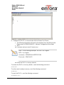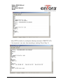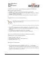
1
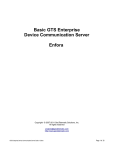
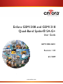
Enfora GSM1308 and GSM1318
Quad-Band Spider® SA-G+
User Guide
GSM1308UG001
Revision: 1.03
6/1/2009
www.enfora.com
GENERAL
TERMS OF USE OF NEW MATERIALS - PLEASE READ CAREFULLY
From time to time, Enfora, in its sole discretion, may make available for download on its
website (www.enfora.com), or may transmit via mail or email, updates or upgrades to, or
new releases of, the firmware, software or documentation for its products (collectively,
'New Materials'). Use of such New Materials is subject to the terms and conditions set
forth below, and may be subject to additional terms and conditions as set forth in Enfora's
Technical Support Policy (posted on its website) and/or any written agreement between
the user and Enfora.
All New Materials are provided AS IS. Enfora makes no warranty or representation with
respect to the merchantability, suitability, functionality, accuracy or completeness of any
such New Materials. The user of such New Materials assumes all risk (known or unknown)
of such use. Enfora reserves all rights in such New Materials. The user shall have only a
revocable and limited license to use such New Materials in connection with the products
for which they are intended. Distribution or modification of any New Materials without
Enfora's consent is strictly prohibited.
IN NO EVENT WILL ENFORA BE RESPONSIBLE FOR ANY INCIDENTAL, INDIRECT,
CONSEQUENTIAL OR SPECIAL DAMAGES AS A RESULT OF THE USE OF ANY NEW
MATERIALS. ENFORA'S MAXIMUM LIABILITY FOR ANY CLAIM BASED ON THE NEW
MATERIALS SHALL NOT EXCEED FIFTY U.S. DOLLARS ($50).
COPYRIGHT
© 2009 Enfora, Inc. All rights reserved. Complying with all applicable copyright laws is the
responsibility of the user. Without limiting the rights under copyright, no part of this
document may be reproduced, stored in or introduced into a retrieval system, or
transmitted in any form or by any means (electronic, mechanical, photocopying, recording
or otherwise), or for any purpose, without the express written permission of Enfora, Inc.
Enfora and the Enfora logo are either registered trademarks or trademarks of Enfora, Inc.
in the United States.
251 Renner Pkwy
Richardson, TX 75080 USA
972-633-4400
Phone: (972) 633-4400
Fax: (972) 633-4444
Email: info@ enfora.com
www.enfora.com
User Guide
Page I
Revision: 1.03
LIMITED WARRANTY
SCOPE
Enfora warrants to the original purchaser of the product that, for a period of one (1) year
from the date of product purchase, the product hardware, when used in conjunction with
any associated software (including any firmware and applications) supplied by Enfora, will
be free from defects in material or workmanship under normal operation. Enfora further
warrants to such original purchaser that, for a period of ninety (90) days from the date of
product purchase, any software associated with the product will perform substantially in
accordance with the user documentation provided by Enfora, and any software media
provided with the product will be free from defects in material or workmanship under
normal operation. Enfora does not warrant that (a) the product hardware or any associated
software will meet the purchaser's requirements, (b) that the operation of the product
hardware or software will be uninterrupted or error-free, or (c) the product, when
integrated in, or combined with, other products or software not supplied by Enfora, will
continue to perform substantially in accordance with the user documentation. This limited
warranty is only for the benefit of the original purchaser and is not transferable. No other
party may act on behalf of such purchaser for the purpose of claiming or exercising any
rights or benefits under or in connection with this limited warranty except as may be
provided in a written agreement between Enfora and such other party.
HARDWARE
During the warranty period applicable to the product hardware, Enfora, at its expense and
in its sole discretion, will repair or replace the product if it is determined to have a covered
hardware defect, provided that the purchaser first notifies Enfora of any such defect,
furnishes Enfora with a proof of purchase, requests and obtains a return merchandize
authorization (RMA) number from Enfora, and returns the product, shipping charges
prepaid, to Enfora under that RMA. If, upon reasonable examination of the returned
product, Enfora does not substantiate the defect claimed by purchaser, or determines that
the defect is not covered under this limited warranty, Enfora will not be required to repair or
replace the product, but may instead reship the product to the purchaser, in which case
purchaser shall be responsible for paying Enfora's usual charges for unpacking, testing,
and repacking the product for reshipment to purchaser. Purchaser shall bear the risk of
loss or damage in transit to any product returned by purchaser to Enfora, or any returned
product not found to be defective or covered under this warranty and reshipped by Enfora
to purchaser. In the event Enfora repairs or replaces a defective product, the repaired or
replacement product will be covered under this limited warranty for the remainder of the
original warranty period on the defective product. If Enfora is unable to repair or replace a
defective product, the purchaser's exclusive remedy shall be a refund of the original
purchase price. Any returned and replaced product, or any product for which Enfora has
refunded the original purchase price, becomes the property of Enfora.
User Guide
P a g e II
Revision: 1.03
SOFTWARE
During the warranty period applicable to the software or its media, Enfora, at its expense,
will replace any defective software or media if purchaser gives written notification of the
defect to the technical support department at Enfora during the applicable warranty
period. Enfora will ship or otherwise transmit the replacement software or media to
purchaser, and purchaser shall be responsible for incorporating any replacement software
in the product. Enfora shall not have any obligation to provide any software bug fixes,
upgrades or new releases except as may be necessary to correct any covered defect of
which purchaser notifies Enfora in writing during the applicable warranty period. Enfora,
from time to time and in its sole discretion, may make available for download on its
website (www.enfora.com) certain software bug fixes, upgrades or new releases for the
product. The purchaser should periodically visit such website to determine whether any
such bug fixes, upgrades or new releases have become available. Download and use of
any such bug fixes, upgrades or new releases is subject to all of the applicable terms and
conditions of Enfora's technical support policy as posted and updated on its website.
EXCEPTIONS AND DISCLAIMERS
Enfora shall have no obligation under this limited warranty for (a) normal wear and tear, (b)
the cost of procurement of substitute products or (c) any defect that is (i) discovered by
purchaser during the warranty period but purchaser does not notify or request an RMA
number from Enfora, as required above, until after the end of the warranty period, (ii)
caused by any accident, misuse, abuse, improper installation, handling or testing, or
unauthorized repair or modification of the product, (iii) caused by use of any software other
than any software supplied by Enfora, or by use of the product other than in accordance
with its documentation or (iv) the result of electrostatic discharge, electrical surge, fire,
flood or similar causes. Unless otherwise provided in a written agreement between the
purchaser and Enfora, the purchaser shall be solely responsible for the proper
configuration, testing and verification of the product prior to deployment in the field.
ENFORA'S SOLE RESPONSIBILITY AND PURCHASER'S SOLE REMEDY UNDER THIS
LIMITED WARRANTY SHALL BE TO REPAIR OR REPLACE THE PRODUCT HARDWARE,
SOFTWARE OR SOFTWARE MEDIA (OR IF REPAIR OR REPLACEMENT IS NOT
POSSIBLE, OBTAIN A REFUND OF THE PURCHASE PRICE) AS PROVIDED ABOVE.
ENFORA EXPRESSLY DISCLAIMS ALL OTHER WARRANTIES OF ANY KIND, EXPRESS
OR IMPLIED, INCLUDING WITHOUT LIMITATION ANY IMPLIED WARRANTIES OF NONINFRINGEMENT, MERCHANTABILITY, SATISFACTORY PERFORMANCE AND FITNESS
FOR A PARTICULAR PURPOSE. IN NO EVENT SHALL ENFORA BE LIABLE FOR ANY
INDIRECT, SPECIAL, EXEMPLARY, INCIDENTAL OR CONSEQUENTIAL DAMAGES
(INCLUDING WITHOUT LIMITATION LOSS OR INTERRUPTION OF USE, DATA,
REVENUES OR PROFITS) RESULTING FROM A BREACH OF THIS WARRANTY OR
BASED ON ANY OTHER LEGAL THEORY, EVEN IF ENFORA HAS BEEN ADVISED OF
THE POSSIBILITY OR LIKELIHOOD OF SUCH DAMAGES.
User Guide
P a g e III
Revision: 1.03
OTHER CONSIDERATIONS
Some jurisdictions may require a longer warranty period than specified above and,
accordingly, for products sold in those jurisdictions the applicable warranty period shall be
extended as required under the laws of those jurisdictions. Furthermore, some
jurisdictions may not allow the disclaimer of implied warranties or the exclusion or limitation
of incidental or consequential damages, so the above disclaimer, limitation or exclusion
may not apply to products sold in those jurisdictions. This limited warranty gives the
purchaser specific legal rights and the purchaser may have other legal rights that vary from
jurisdiction to jurisdiction.
In some instances, certain aspects of the product warranty may also be covered in a
separate written agreement between Enfora and the distributor or reseller, if any, from
whom purchaser purchased the product. That agreement may provide, for example, a
different product return procedure that may also be available to purchaser (e.g., the
product may be returned to Enfora through that distributor or reseller).
OTHER CONSIDERATIONS
This limited warranty shall be governed by the laws of the State of Texas, United States of
America, without regard to conflict of laws principles. This limited warranty shall not be
governed in any respect by the United Nations Convention on Contracts for the
International Sale of Goods.
REGULATORY COMPLIANCE
FCC
The modem was tested and certified to meet FCC Parts 15 in a stand-alone configuration,
which demonstrated that the GSM1308 and GSM1318 SA-G+ complies with Part 15
emission limits. FCC Part 22 & Part 24 is covered by the Enfora Enabler-IIIG "modular
approval" process for a transmitter. This approach, described by FCC Public Notice DA
00-131407 released June 26, 2000, is intended to afford relief to equipment
manufacturers by eliminating the requirement for obtaining a new equipment authorization
for the same transmitter when installed in a new device.
In order to use the GSM1308 and GSM1318 SA-G+ without additional FCC certification
approvals, the installation must meet the following conditions:
•
•
•
User Guide
A separation distance of at least 20 cm (7.87 inches) between the antenna and
the body of the user and other persons must be maintained at all times.
GSM 850 mode: With the maximum conducted power at 32 dBm, the
maximum antenna gain is 4.5 dBi (2.35 dBd) in order to meet maximum 7 watt
ERP for mobile transmitters and MPE (Maximum Permissible Exposure)
requirement of General Population/Uncontrolled exposures.
GSM 1900 mode: With the maximum conducted power at 31dBm, the
maximum antenna gain is 2 dBi in order to meet maximum 2 watt EIRP for
P a g e IV
Revision: 1.03
mobile transmitters and MPE (Maximum Permissible Exposure) requirement of
General Population/Uncontrolled exposures.
RF EXPOSURE
Your GSM1308 or GSM1318 SA-G+ modem is a radio transmitter and receiver. It is
designed and manufactured not to exceed the emissions limits for exposure to radio
frequency (RF) energy set by the Federal Communications Commission (FCC) of the U.S.
Government. These limits are part of comprehensive guidelines and establish permitted
levels of RF energy for the general population. These guidelines are based on the safety
standards previously set by the U.S. and international standards bodies. The standards
include a substantial safety margin designed to assure the safety of all persons, regardless
of age and health.
The exposure standard for wireless RF devices, such as the GSM1308 and GSM1318 SAG+ modem, employs a unit of measurement known as the Specific Absorption Rate, or
SAR. The SAR limit set by the FCC is 1.6W/kg. SAR values at or below that limit are
considered safe for the general public.
Before a wireless RF device is made available for sale to the Public, it must be tested and
certified to the FCC that it does not exceed the SAR limits established by the FCC. Tests
for SAR are conducted using the positions and locations (e.g., at the ear or worn on the
body) as required by the FCC for each device model. The Spider AT has been tested and
meets the FCC RF exposure guidelines when used against the body under normal usage
conditions.
R&TTE
The GSM1308 and GSM1318 SA-G+ modem has been fully tested and complies with all
the requirements of EN301 489-1, EN301 489-7 and EN60950-1:2001. Compliance to EN
301 511 has been demonstrated by testing on both the GSM1308 and the integrated
GSM0308 module. At the separation distance of at least 20 cm (7.87 inches) between the
antenna and the body of the user and other persons, the product also meet EN50392
MPE requirement.
DISCLAIMER
The information and instructions contained within this publication comply with all FCC,
GCF, PTCRB, R&TTE, IMEI and other applicable codes that are in effect at the time of
publication. Enfora disclaims all responsibility for any act or omissions, or for breach of
law, code or regulation, including local or state codes, performed by a third party.
Enfora strongly recommends that all installations, hookups, transmissions, etc., be
performed by persons who are experienced in the fields of radio frequency technologies.
Enfora acknowledges that the installation, setup and transmission guidelines contained
within this publication are guidelines, and that each installation may have variables outside
User Guide
Page V
Revision: 1.03
of the guidelines contained herein. Said variables must be taken into consideration when
installing or using the product, and Enfora shall not be responsible for installations or
transmissions that fall outside of the parameters set forth in this publication.
User Guide
P a g e VI
Revision: 1.03
TABLE OF CONTENTS
General ............................................................................................................................ 1 COPYRIGHT .................................................................................................................... 1 LIMITED WARRANTY ....................................................................................................... 2 SCOPE ............................................................................................................................ 2 Hardware ......................................................................................................................... 2 SOFTWARE ..................................................................................................................... 3 EXCEPTIONS AND DISCLAIMERS ................................................................................... 3 OTHER CONSIDERATIONS ............................................................................................. 4 REGULATORY COMPLIANCE .......................................................................................... 4 FCC ................................................................................................................................. 4 RF EXPOSURE................................................................................................................. 5 R&TTE
................................................................................................................... 5 Table of Contents ............................................................................................................. 7 Table of Figures ................................................................................................................ 8 Table of Tables ................................................................................................................. 8 1 Introduction .................................................................................................... 1 1.1 About the GSM/GPRS SA-G+ ........................................................................ 1 1.2 About this Manual .......................................................................................... 1 1.2.1 Manuals ......................................................................................................... 1 1.2.2 Application Notes ........................................................................................... 1 1.2.3 Technical Notes.............................................................................................. 2 1.3 System Requirements .................................................................................... 2 1.4 SA-G+ Front and Back View ........................................................................... 3 2 Installation ...................................................................................................... 4 2.1 Subscriber Identity Module (SIM) Card ............................................................ 4 2.2 Eight (8) Pin Connector ................................................................................... 5 2.2.1 GPIO1 (Input/Output) ...................................................................................... 7 2.2.1.1 2.2.1.2 2.2.1.3 GPIO 1 Electrical Specifications .................................................................................. 7 GPIO1 as an Input ...................................................................................................... 7 GPIO1 as an Output ................................................................................................... 7 User Guide
P a g e VII
Revision: 1.03
2.2.2 GPIO2 (Input/Output) Programmable Pull-Up System ..................................... 8 2.2.2.1 2.2.2.2 2.2.2.3 2.3 GPIO 2 Electrical Specifications .................................................................................. 8 GPIO2 as Pull-Down System ...................................................................................... 8 GPIO2 as a Pull-Up System........................................................................................ 8 Connecting the Serial Cable ......................................................................... 10 2.4 Connecting the GSM/GPRS Antenna ........................................................... 11 2.5 LED Functions .............................................................................................. 12 2.6 Mounting the SA-G+ .................................................................................... 12 3 Firmware Upgrade ........................................................................................ 13 4 Configure the Computer and Verify Correct Communications ....................... 14 5 Configure the SA-G+ to talk to the Enfora Server .......................................... 20 6 Verifying Server Connectivity ......................................................................... 26 7 Tech Support ............................................................................................... 28 TABLE OF FIGURES
Figure 1 - Front view of GSM/GPRS SA-G+ modem......................................................... 3 Figure 2 - Rear view of GSM/GPRS SA-G+ modem. ........................................................ 3 Figure 3 - Inserting a SIM Card in a GSM/GPRS SA-G+ Module ....................................... 4 Figure 4 Molex Connector and Pins .................................................................................. 7 Figure 5- Serial Pin-out ................................................................................................... 10 Figure 6 GSM/GPRS SA-G+ Connecting the Antenna .................................................... 11 Figure 7 Mounting Dimensions ....................................................................................... 12 TABLE OF TABLES
Table 1 Cable Assembly Parts .......................................................................................... 5 Table 2 8 pin I/O Connector Interface ............................................................................... 6 Table 3 GSM Operating Power ......................................................................................... 9 Table 4 REG LED Behavior During Firmware Upgrade .................................................... 13 User Guide
P a g e VIII
Revision: 1.03
Enfora GSM1308 and
GSM1318
Quad-Band Spider®
SA-G+
1 Introduction
1.1 ABOUT THE GSM/GPRS SA-G+
The GSM/GPRS SA-G+ is a compact, stand-alone wireless IP (GSM/GPRS)
modem. The GSM/GPRS SA-G+ is designed for computing devices operating
Windows XP and Windows 2000 or any serial-enabled platform. The SA-G+ can
be used as a stand-alone serial device with other vertical applications. Enfora’s
GSM/GPRS SA-G+ provides maximum versatility in a single affordable device with
2 User-Definable Input/Outputs (I/O) and 1 User-Definable Output.
1.2 ABOUT THIS MANUAL
Contained in this manual are instructions on how to install and configure the
GSM/GPRS SA-G+ modem. Please follow the instructions herein closely to avoid
damaging the GSM/GPRS SA-G+.
The GSM/GPRS SA-G+ modem contains an Enfora Enabler-IIIG OEM module.
Detailed information pertaining to the specifications and operation of the module will
pertain, in part, to the GSM/GPRS SA-G+ platform.
The information can be accessed at the Enfora website (http://www.enfora.com)
under Support and Resources.
Refer to the following documentation for additional information, if required:
1.2.1 MANUALS
GSM0308AT001 - Enfora IIIG Module AT Command Set Reference
GSM0308UG001 - Enfora GSM-GPRS Family API Reference
1.2.2 APPLICATION NOTES
GSM0000AN002 - Enabler-G PPP Configuration for Windows 2000
GSM0000AN003 - Enabler-G Data Circuit Switched Call Configuration and Use
GSM0000AN004 - Enabler-G SMS Configuration and Use
GSM0000AN005 - Enabler-G Automated Network Connection Configuration and
Use
GSM0000AN006 - Enabler-G Module Status Query
GSM0000AN007 - Enabler-G Status Reporting
GSM0000AN008 - Enabler-G PPP Configuration for Windows XP
User Guide
Page 1
Revision: 1.03
Enfora GSM1308 and
GSM1318
Quad-Band Spider®
SA-G+
GSM0000AN009 - Dynamic IP Assignment Support
GSM0000AN011 - PAD Configuration and Use
GSM0000AN012 - Network Transparency Configuration for PAD
GSM0000AN013 - Enabler-G Sleep Mode Configuration and Use
GSM0000AN014 - Anytime PPP API Access
GSM0000AN015 - Event Monitor and Reporting Overview
GSM0000AN016 - How to Send SMS Messages to an E-Mail Address
GSM0000AN017 - SMTP Mail Access via TCP PAD
GSM0000AN018 - USNO NTP Network Time Service TCP PAD
GSM0000AN019 - Network Configuration Worksheet
GSM0000AN020 - Comparison of Modem Power Control Pins in Enfora Modules
GSM0000AN022 - Sending AT Commands over SMS
GSM0000AN023 - Configure the Modem to talk to the Enfora Server
GSM0000AN024 - Enhanced Test Mode Commands
GSM0000AN025 - Enabler IIG Network Personalization
GSM0000AN026 - Using a Terminal Program to Test PAD
GSM0000AN027 - AT$ACTIVE Command Implementation Behavior
1.2.3 TECHNICAL NOTES
GSM0000TN001 - Enabler-G Firmware Upgrade
GSM0000TN002 - Enabler-G PPP Negotiation Sequence
GSM0000TN006 - UDP Wakeup Message Header Decoding
GSM0000TN007 - Enabler-G 3-Wire Serial Interface Requirements
GSM0000TN009 - Server Application Design Considerations for Dynamic IP
GSM0000TN012 - Engineering Mode Manual
1.3 SYSTEM REQUIREMENTS
•
•
User Guide
Windows XP and Windows 2000 operating systems or other serial-enabled
platform.
One standard RS-232 serial port for GSM/GPRS SA-G+ configuration.
Page 2
Revision: 1.03
Enfora GSM1308 and
GSM1318
Quad-Band Spider®
SA-G+
1.4 SA-G+ FRONT AND BACK VIEW
Figure 1 - Front view of GSM/GPRS SA-G+ modem.
Figure 2 - Rear view of GSM/GPRS SA-G+ modem.
User Guide
Page 3
Revision: 1.03
Enfora GSM1308 and
GSM1318
Quad-Band Spider®
SA-G+
2 Installation
2.1 SUBSCRIBER IDENTITY MODULE (SIM) CARD
The SIM, an integral part of any GSM terminal device, is a “smart card” that is
programmed with subscriber information. The user information consists of an
International Mobile Subscriber Identity (IMSI) number, which is registered with the
GSM service provider, and an encryption Ki (pronounced “key”). This information
consists of a microprocessor and memory installed on a plastic card. To install the
SIM card into the modem, insert the SIM card in the modem as shown below in
Figure 3.
Note: The SIM is not provided with the SA-G+ modem. The
SIM must be obtained from the GSM service provider and must
be provisioned by the operator for data and/or voice. Always
take care to protect the SIM: the GSM terminal will not operate
without the SIM installed.
Insert the SIM card here –
please note that the notch
must be in the upper left
hand corner.
After inserting the SIM card, you
MUST move the SIM lock switch to
the left. If the lock is open, there
will not be power to the SIM.
Figure 3 - Inserting a SIM Card in a GSM/GPRS SA-G+ Module
User Guide
Page 4
Revision: 1.03
Enfora GSM1308 and
GSM1318
Quad-Band Spider®
SA-G+
2.2 EIGHT (8) PIN CONNECTOR
The GSM/GPRS SA-G+ modem can utilize input power ranging from 6 Vdc to 40
Vdc. If your unit did not include an optional power supply, or if you wish to
configure a separate power interface, the following connector parts are the Enfora
recommended parts that can be used to mate with the existing modem power
connector:
Connector:
Manufacturer:
Molex
Part Number:
43025-0800
Pins:
Manufacturer:
Molex
Part Number:
43030-0008 20-24 AWG
43030-0011 26-30 AWG
Crimp Tool:
Manufacturer:
Molex
Part Number:
63811-2800
Table 1 Cable Assembly Parts
User Guide
Page 5
Revision: 1.03
Enfora GSM1308 and
GSM1318
Quad-Band Spider®
SA-G+
During installation take precautions to help ensure proper operation of the SA-G+.
Do not create loops, sharp bends or crimps in the cables. Use proper terminations
on all power cables.
Note: : If the SA-G+ will be used in a vehicle, attach all cables to the
vehicle and equipment in such a way to reduce stress or wear
caused by vibration generated by moving vehicles.
The user can purchase the optional eight (8) pin external I/O connector for the
Enfora SA-G+ that can be used to interface with other devices. Enfora can provide
an optional cable and connector (Part #CAB1308). The user also has the option of
building his/her own cable. Table 2 describes the pin functionality for this 8 pin I/O
connector. Pins that are not planned for usage can be left open without anything
connected to them.
Pin Number
Functionality
Description
Pin – 1
Microphone +
Pin – 2
Headset +
Pin – 3
Ground
Pin – 4
Ground
Pin – 5
Supply Voltage
(6-40V)
Pin – 6
User Controlled IO1
(3.3 – 40V) – Uses GPIO1 of the
Enabler IIIG Module
Pin – 7
User Controlled IO2
Pin – 8
User Controlled Output
(3.3 – 40V) – Uses GPIO6 of the
Enabler IIIG Module
(1.5A sink) – Uses GPIO8 of the
Enabler IIIG Module. This GPIO’s
state is latched during a reset.
Table 2 8 pin I/O Connector Interface
User Guide
Page 6
Revision: 1.03
Enfora GSM1308 and
GSM1318
Quad-Band Spider®
SA-G+
Figure 4 Molex Connector and Pins
2.2.1 GPIO1 (INPUT/OUTPUT)
2.2.1.1 GPIO 1 ELECTRICAL SPECIFICATIONS
• Input VIH: >2.2 V
• Input VIL: <1 V
• Output VOH: 3 V
• Output VOL: 0
• Max Source Current: Approximately 350 μA
• Max Sink Current: 3.7 mA @ 40 V, 0.13 W
2.2.1.2 GPIO1 AS AN INPUT
Set the bus direction to be “input” by using the “AT$IOGP1=1” command.
Verify that GPIO1 is set to be an input by using the “AT$IOCFG?” command.
2.2.1.3 GPIO1 AS AN OUTPUT
Change GPIO1 to be an output by using the “AT$IOCFG=xxx” command.
Set the bus direction to be an output by using the “AT$IOGP1=0” command.
User Guide
Page 7
Revision: 1.03
Enfora GSM1308 and
GSM1318
Quad-Band Spider®
SA-G+
2.2.2 GPIO2 (INPUT/OUTPUT) PROGRAMMABLE PULL-UP SYSTEM
2.2.2.1 GPIO 2 ELECTRICAL SPECIFICATIONS
• Input VIH: >2.2 V
• Input VIL: <1 V
• Output VOH: 3 V
• Output VOL: 0
• Max Source Current: Approximately 320 μA
• Max Sink Current: 3.7 mA @ 40 V, 0.13 W
2.2.2.2 GPIO2 AS PULL-DOWN SYSTEM
Set GPIO2 to 0 by using the “AT$IOPULUP=0” command.
2.2.2.3 GPIO2 AS A PULL-UP SYSTEM
Set GPIO2 to 1 by using the “AT$IOPULUP=1” command.
*Set the bus direction as described in 3.2.1 using the AT$IOGP2=x command
where x is 0 or 1..
User Guide
Page 8
Revision: 1.03
Enfora GSM1308 and
GSM1318
Quad-Band Spider®
SA-G+
The following table provides the power characteristics of the GSM/GPRS SA-G+
modem.
Band
Mode
Avg (mA)
Peak (A@dBm)
GSM 850
1 TX/1 RX
200
1.30@33
EGSM 900
Idle
50 DRX 5
DCS 1800
1 TX/1 RX
160
PCS 1900
Idle
50 DRX 5
Sleep
20
0.92@30
Table 3 GSM Operating Power
Warning: Use of the device outside of the specified voltage
range may result in damage to the device and/or
undesirable results.
User Guide
Page 9
Revision: 1.03
Enfora GSM1308 and
GSM1318
Quad-Band Spider®
SA-G+
2.3 CONNECTING THE SERIAL CABLE
To connect the SA-G+ with a local computing device, connect one end (male end)
of the 9-wire RS232 Serial Cable to the SA-G+ port labeled "Serial" and connect
the other end to a computer.
The following figure provides the SA-G+ serial pin-out information.
Figure 5- Serial Pin-out
User Guide
P a g e 10
Revision: 1.03
Enfora GSM1308 and
GSM1318
Quad-Band Spider®
SA-G+
2.4 CONNECTING THE GSM/GPRS ANTENNA
The antenna is supplied by the user. The antenna must have a nominal impedance
of 50 Ohms. The VSWR must be less than 2.0:1. System antenna gain should be
0-2 dB for optimum performance.
The GSM/GPRS SA-G+ operates at the 850/900/1800 and 1900 MHz frequency
bands. Care needs to be taken when connecting the antenna since the right type
of antenna will be required for proper operation of the modem. The antenna
connector on the GSM/GPRS SA-G+ modem is SMA Female. The antenna has to
be connected to the connector labeled “Antenna” as shown below in Figure5.
Connect the
GSM/GPRS
antenna here.
Figure 6 GSM/GPRS SA-G+ Connecting the Antenna
User Guide
P a g e 11
Revision: 1.03
Enfora GSM1308 and
GSM1318
Quad-Band Spider®
SA-G+
2.5 LED FUNCTIONS
The GSM/GPRS SA-G+ modem has one green LED on the front panel.
REG: Indicates GSM network registration status. Flashing when attempting to
register on a GSM network. Solid when the modem is registered with a GSM
network.
2.6 MOUNTING THE SA-G+
The GSM/GPRS SA-G+ includes two mounting options. The modem housing
contains four thru holes that can utilize number 2 screws for securing the device.
The other option available is the inclusion of four threaded holes for securing
screws to be used to secure the device.
Figure 7 Mounting Dimensions
User Guide
P a g e 12
Revision: 1.03
Enfora GSM1308 and
GSM1318
Quad-Band Spider®
SA-G+
3 Firmware Upgrade
To see if there is updated firmware for the SA-G+, please visit:
http://www.enfora.com > support
You will need to obtain a login to the website from Enfora Tech Support in order to
download the firmware.
During the firmware upgrade, the LED’s will display the following behavior:
SIM Installed
(registered with
network)
REG LED
Behavior
SIM Not Installed
(registering with
network, LED is on)
SIM Not Installed
(registering with
network, LED is off)
Solid
Solid
Off
Table 4 REG LED Behavior During Firmware Upgrade
User Guide
P a g e 13
Revision: 1.03
Enfora GSM1308 and
GSM1318
Quad-Band Spider®
SA-G+
4 Configure the Computer and Verify
Correct Communications
Note: The following examples use Windows 2000 and
HyperTerminal. Any Terminal program should work, using the
parameters in Step 1
1. Default Serial Parameters
a.
b.
c.
d.
e.
Autobaud (power up message at115200 baud rate)
8 data bits
1 stop bit
No Parity
Flow Control = None
2. Determine which Com port to use
f. On older computers, there is usually a built in Com port. This is normally
Com1.
g. If you are using a USB-to-serial converter, you will need to determine
which Com port it is installed on.
Note: If the USB-to-serial converter has not been installed,
install the necessary drivers per the instruction supplied by
your USB-to-Serial device. Then leave the device
unplugged.
h. Open up the System Properties window. This is done through the
Control Panel > System or right-click on My Computer and select
Properties. Select the Hardware Tab. On Windows 2000 the screen
looks like the following:
User Guide
P a g e 14
Revision: 1.03
Enfora GSM1308 and
GSM1318
Quad-Band Spider®
SA-G+
i.
User Guide
Select the Device Manager button. Expand the Ports section by selecting
the + sign beside Ports. Your window should look like the following:
P a g e 15
Revision: 1.03
Enfora GSM1308 and
GSM1318
Quad-Band Spider®
SA-G+
j.
Plug in the USB-to-Serial converter. The window should change to show
the USB-to-Serial converter installed.
k. Most devices will show the Com port next to the device name. Record
this number. In this case, it is COM12.
Note: Make sure there is no "!" or "X" next to the USB device. If you
see an "!" or an "X," the device is not properly installed and will not
work
User Guide
P a g e 16
Revision: 1.03
Enfora GSM1308 and
GSM1318
Quad-Band Spider®
SA-G+
3. Start HyperTerminal
On Windows 2000, click on:
Start>Programs>Accessories>Communications>HyperTerminal
l.
You should see the following screen.
m. Enter a name for the Connection. In this example, the Name is Enfora
Com1.
n. Click OK.
o. The next window that will appear is the Connect To window.
User Guide
P a g e 17
Revision: 1.03
Enfora GSM1308 and
GSM1318
Quad-Band Spider®
SA-G+
p. Change the Connect Using setting to the Com port that was determined
in Step B.
q. Click OK.
r. The next window is the Port Settings window.
User Guide
P a g e 18
Revision: 1.03
Enfora GSM1308 and
GSM1318
Quad-Band Spider®
SA-G+
s. Make sure the settings match the example.
t. Click OK.
u. Now the Main Program Window should appear.
User Guide
P a g e 19
Revision: 1.03
Enfora GSM1308 and
GSM1318
Quad-Band Spider®
SA-G+
5 Configure the SA-G+ to talk to the
Enfora Server
4. Connect and verify Serial connectivity with the Enfora SA-G+.
v. Connect the PC serial connector to the SA-G+ serial port.
Note: In the following instructions, <CR> means using the Enter Key
on the keyboard
With HyperTerminal open, hit the Enter key. The SA-G+ should respond with OK. If
you do not see this response, double-check your connections.
w. Type AT<CR>. The SA-G+ should respond with OK. If you do not see
the letters AT, send the following command to the SA-G+: ATE1<CR>
x. Type ATI<CR>. The SA-G+ should respond with Enfora, Inc. If you get
any different response, you are not connected to the Enfora SA-G+.
User Guide
P a g e 20
Revision: 1.03
Enfora GSM1308 and
GSM1318
Quad-Band Spider®
SA-G+
5. Configure the SA-G+ to communicate with the Enfora Test Server.
y. The following information will need to be obtained from the SIM provider.
Please refer to GSM0000AN019 – Network Configuration Worksheet.
z. APN
aa. Username and password (If necessary.)
Note: : In the following examples, the SIM is for Cingular.
APN = isp.cingular
Username = [email protected]
Password = CINGULAR1
bb. Reset the SA-G+ to factory defaults:
To restore the SA-G+ to factory defaults, send the following command:
AT&F<CR>
To write current config to memory, send the following command:
AT&W<CR>
To reset the SA-G+, send the following command:
AT$RESET<CR>
User Guide
P a g e 21
Revision: 1.03
Enfora GSM1308 and
GSM1318
Quad-Band Spider®
SA-G+
cc. Configure the SA-G+ to Access the GPRS network.
To inform the SA-G+ of the proper APN, send the following command:
AT+CGDCONT=1,”IP”,”apn”<CR> (substitute the letters apn for
the supplied apn.)
To inform the SA-G+ of the proper username and password, (if necessary) send the
following command:
AT%CGPCO=1,”username,password”<CR> (substitute the correct
username and password)
To configure the SA-G+ to enable auto GPRS registration, send the following
command:
AT$AREG=2<CR>
Store the current configuration to memory, send the following command:
AT&W<CR>
Reset the SA-G+ by removing power or sending the command.
AT$RESET<CR>.
Verify GSM status by sending the following command:
AT+CREG?<CR>
If everything is working, you should receive one of two responses:
+CREG: 0,1 (GSM registered to home network)
OR
+CREG: 0,5 (GSM registered roaming.)
Verify GPRS status by sending the following command:
AT%CGREG?<CR>
If everything is working, you should receive one of two responses:
%CGREG: 0,1 (GPRS registered to home network)
Or
%CGREG: 0,5 (GPRS registered roaming.)
User Guide
P a g e 22
Revision: 1.03
Enfora GSM1308 and
GSM1318
Quad-Band Spider®
SA-G+
Verify GPRS activation by sending the following command: AT$NETIP?<CR>
If the response is non-zero, then everything is working. Skip to Step 10.
User Guide
P a g e 23
Revision: 1.03
Enfora GSM1308 and
GSM1318
Quad-Band Spider®
SA-G+
If AT$NETIP returns all zeros, send the following command: AT$CGEER<CR>
There are three common responses:
•
•
•
•
$CGEER: no PDP reject cause (Everything should be working OK)
$CGEER: requested service option not subscribed (APN is incorrect or SIM has
not been enabled for data mode.)
$CGEER: user authentication failed (username and/or password is incorrect.)
Configure the SA-G+ to access the Enfora Server.
Note: To configure the SA-G+ for server interoperability, several
things have to be addressed.
•
•
•
Most GPRS configurations are Mobile Originate only. The mobile SA-G+ must
initiate a conversation with a remote server before the remote server can talk to
the SA-G+.
IP addresses are dynamically assigned and can change.
Some IP addresses are NAT and are non-routable IP addresses.
These issues are addressed with the following configuration commands.
The examples will use the following information:
•
•
•
Modem ID/name = “SAG_Test”
Remote Server DNS address = apitest.enfora.com
Remote Server IP port = 1721
Give the SA-G+ a unique name.
•
User Guide
Send the following command: AT$MDMID=”SAG_Test” This command,
combined with the wakeup message, will allow the server to associate a Public
IP address with a specific SA-G+ and create a window of opportunity where the
server can send commands to the SA-G+
P a g e 24
Revision: 1.03
Enfora GSM1308 and
GSM1318
Quad-Band Spider®
SA-G+
Configure the SA-G+ to talk with a specific server.
•
Send the following command: AT$FRIEND=1,1,”apitest.enfora.com”
Set the port number
•
Send the following command: AT$UDPAPI=,1721
Enable periodic messages (wakeup) to be sent to the server every 60 seconds
•
User Guide
Send the following command: AT$WAKEUP=1,1
P a g e 25
Revision: 1.03
Enfora GSM1308 and
GSM1318
Quad-Band Spider®
SA-G+
6 Verifying Server Connectivity
Note: For the following tests, Java Runtime must be installed on the
computer. (To install Java Runtime, please visit the Java website
here: http://www.java.com/en/download/manual.jsp)
6. Start Internet Explorer and enter the following URL:
http://apitest.enfora.com/udpapp/
7. Enter the name used in the MDMID command in the box. Select Connect.
8. Select the tab with the SA-G+ name. Within approximately 60 seconds the
wakeup messages should be seen in the window.
User Guide
P a g e 26
Revision: 1.03
Enfora GSM1308 and
GSM1318
Quad-Band Spider®
SA-G+
9. Enter the following command in the command/ data block: ATI
10. Select Write.
11. Verify that you see the following the SA-G+ response with Enfora, Inc. If so, you
have successfully configured the SA-G+ to talk with the server.
User Guide
P a g e 27
Revision: 1.03
Enfora GSM1308 and
GSM1318
Quad-Band Spider®
SA-G+
7 Tech Support
For problems stemming from your network access, contact your GSM/GPRS
carrier service. For technical support and customer service dealing with the
modem itself, contact the company where you purchased the product. If you
purchased the product directly from Enfora, visit the Support and Resources page
on the Enfora website: http://www.enfora.com.
User Guide
P a g e 28
Revision: 1.03