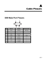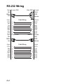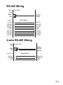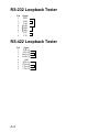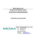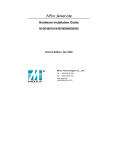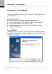
1
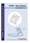
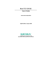
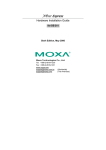
NPort Server Lite
Hardware Installation Guide
For DE-301/331 & DE-302/304/332/334
Fourth Edition, June 2008
www.moxa.com/product
© 2008 Moxa Inc., all rights reserved.
Reproduction without permission is prohibited.
NPort Server Lite
Hardware Installation Guide
The software described in this manual is furnished under a license agreement and may be
used only in accordance with the terms of that agreement.
Copyright Notice
Copyright © 2008 Moxa Inc.
All rights reserved.
Reproduction without permission is prohibited.
Trademarks
MOXA is a registered trademark of Moxa Inc.
All other trademarks or registered marks in this manual belong to their respective
manufacturers.
Disclaimer
Information in this document is subject to change without notice and does not represent a
commitment on the part of Moxa.
Moxa provides this document “as is,” without warranty of any kind, either expressed or
implied, including, but not limited to, its particular purpose. Moxa reserves the right to
make improvements and/or changes to this manual, or to the products and/or the
programs described in this manual, at any time.
Information provided in this manual is intended to be accurate and reliable. However,
Moxa assumes no responsibility for its use, or for any infringements on the rights of third
parties that may result from its use.
This product might include unintentional technical or typographical errors. Changes are
periodically made to the information herein to correct such errors, and these changes are
incorporated into new editions of the publication.
Technical Support Contact Information
www.moxa.com/support
Moxa Americas:
Toll-free: 1-888-669-2872
Tel: +1-714-528-6777
Fax: +1-714-528-6778
Moxa China (Shanghai
office):
Toll-free: 800-820-5036
Tel: +86-21-5258-9955
Fax: +86-10-6872-3958
Moxa Europe:
Tel: +49-89-3 70 03
99-0
Fax: +49-89-3 70 03
99-99
Moxa Asia-Pacific:
Tel: +886-2-8919-1230
Fax: +886-2-8919-1231
Table of Contents
1.
Introduction....................................................................... 1-1
Features ........................................................................................ 1-2
Specifications ................................................................................ 1-2
Package Checklist......................................................................... 1-3
Parts of the Server ........................................................................ 1-5
2.
Connecting the Hardware ................................................ 2-1
Choosing a Location ..................................................................... 2-1
Desktop .................................................................................2-1
Wall or Cabinet ......................................................................2-2
DIN Rail .................................................................................2-3
Network Connection...................................................................... 2-5
Power Connection......................................................................... 2-6
Serial Connection.......................................................................... 2-6
3.
Using the LCD Control Panel........................................... 3-1
4.
Troubleshooting................................................................ 4-1
Installation and Configuration Troubleshooting............................. 4-1
Programming Problems ................................................................ 4-5
A.
Cable Pinouts....................................................................A-1
DB9 Male Port Pinouts.................................................................. A-1
RS-232 Wiring............................................................................... A-2
RS-422 Wiring............................................................................... A-3
2-wire RS-485 Wiring .................................................................... A-3
RS-232 Loopback Tester............................................................... A-4
RS-422 Loopback Tester............................................................... A-4
B.
Declaration of Conformity................................................B-2
1
1.
Introduction
Welcome to Moxa’s NPort Server Lite, an industrial serial device server that
greatly enhances the ability of a Windows host (i.e., PC) to control multiple
serial devices over a TCP/IP-based Ethernet network.
This chapter is an introduction to the NPort Server Lite and includes the
following:
y
y
y
y
Features
Specifications
Package Checklist
Parts of the Server
The NPort Server Lite connects a Windows host to an asynchronous RS-232 or
RS-422/485 serial port through a 10/100Mbps TCP/IP Ethernet network. Any
device that supports the asynchronous communications protocol can be
connected to the network. The NPort Server Lite works like an add-on multiport
serial board but with one major advantage—the TCP/IP network. By networking
the serial ports, the NPort Server Lite allows you to control asynchronous serial
devices from virtually anywhere in the world.
The following table illustrates the number of ports and type of serial interface for
each NPort Server Lite model:
1 port
2 ports
4 ports
RS-232
NPort
DE-301
NPort
DE-302
NPort
DE-304
RS-422, RS-485
NPort
DE-331
NPort
DE-332
NPort
DE-334
Real COM drivers are included that allow the Windows operating system to
recognize the networked serial ports as if they were physically attached to the
host, simplifying application development. The NPort Server Lite provides basic
1-1
transmit/receive data functions as well as RTS, CTS, DTR, DSR, and DCD
control signals.
The NPort Server Lite can be used with your existing applications that support
serial communication. A utility program is included that provides simple
step-by-step installation instructions and a maintenance wizard that gives you
easy access to your asynchronous devices.
Features
y
y
y
y
y
y
y
y
y
y
Auto-detecting 10/100 Mbps Ethernet
RS-232 or RS-422/485 serial interface
1, 2, or 4 port models
LCD control panel with IP address display and configuration
Built-in Ethernet and TCP/IP protocol
Each port configurable for Driver, TCP Server, TCP Client, or UDP
Server/Client operation mode
Pair Connection operation available for DE-301 and DE-331
Windows Real COM drivers and Linux real tty drivers
Automatic network connection recovery
Desktop and DIN-rail installation
Specifications
Hardware
Processor
I/O Controller:
DE-301/331
DE-302/332
DE-304/334
Memory
Connector Type
1-2
16 bit CPU
16C550C or compatible × 1
16C550C or compatible × 2
16C550C or compatible × 4
512 KB
DB9 Male
Interface
LAN
Serial
No. of Ports
Signals:
RS-232
RS-422
RS-485
Serial Parameters
Speed
Parity
Data bits
Stop bits
Auto-detecting 100Base-TX (10/100 Mbps)
RS-232 or RS-422/485
1/2/4
TxD, RxD, RTS, CTS, DTR, DSR, DCD, GND
TxD+/-, RxD+/-, RTS+/-, CTS+/-, GND
Data+/-, GND
50 bps to 230.4 Kbps
None, even, odd, space, mark
5, 6, 7, 8
1, 1.5, 2
Power and Environment
Power Requirements
9 to 30 VDC, 1.05A/9V
Operating Temp.
0 to 55℃
Operating Humidity
5 to 95% RH
Storage Temp.
-20 to 85℃
Dimensions
155 × 105 × 33 mm (W × D × H)
Surge Protection
15 KV ESD for serial ports
Magnetic Isolation
1.5 KV for Ethernet
Regulatory Approvals
FCC, CE, UL, CUL, TÜV
Note: If you need a product with optical isolation, the MOXA’s Transio A53 is a
smart, bi-directional converter that can be used with the NPort Server Lite
to provide up to 2 KV of optical isolation.
Package Checklist
y
y
y
y
NPort Server Lite
NPort Server Lite Hardware Installation Guide
NPort Family Software Installation Guide
Crossover 10/100 Mbps Ethernet cable
1-3
y
Power adaptor (110V or 230V)
y
Drivers for Windows, Linux, and Unix (on CD)
Optional Accessories
y
A52: smart RS-232 to RS-422/485 bi-directional converter
y
A53: smart RS-232 to RS-422/485 bi-directional converter;
supports optical isolation protection (2 KV)
y
Mounting plates, brackets and screws
1-4
Parts of the Server
Front Panel View
1
1
1
1
NOTE: 4-port model shown on left
Top Panel View
3
1. DB9 male serial ports
4
2. PWR LED
5
3. LINK LED
6
4. TRAFFIC LED
DE-304 RS-232 Device Server
2
10/100M Ethernet
PWR
LINK
TRAFFIC
NP61405 SN:61405
192.168.127.254
Lite
T
MENU
P1
P2
T
P3
SEL
5. LCD control panel screen
Note: Before IP address is
received from DHCP/BOOTP
server, unit displays
“DHCP/BOOTP fail” message
every second.
P4
Rear Panel View
10/100Mbps
Ethernet
DC-IN
9V~30VDC
Reset
6. LCD control panel buttons
7
8
9
7. Reset button
Note: Hold down for 3 sec to
erase password.
Bottom Panel View
10
10
Moxa Technologies Co., Ltd.
11
11
8. 100BaseTx Ethernet port
9. Power input
10. Rubber base pads
Made in Taiwan
10
10
11. Mounting bracket area
12. Heat vent
Right Panel View
12
1-5
2
2.
Connecting the Hardware
Now that you have been introduced to the NPort Server Lite's features and
specifications, it’s time to set up the hardware. The following topics are covered
in this chapter:
y
y
y
y
Choosing a Location
y
Desktop
y
Wall or Cabinet
y
DIN Rail
Network Connection
Power Connection
Serial Connection
Choosing a Location
There are three placement options available:
y
y
y
place on a desktop
fix to a wall or inside a cabinet
fix to a 35-mm DIN rail
Desktop
The NPort Server Lite may be placed on a clean, flat, well-ventilated desktop.
There are four rubber pads attached to the bottom of the server, and we
recommend leaving sufficient room between the unit and neighboring equipment
to create enough clearance for air to circulate.
Do not put anything on top of the unit, since this could damage the internal
components and obscure the server’s LCD screen.
2-1
Wall or Cabinet
The two mounting plates included with the NPort Server Lite can be used to
attach the server to a wall or to the inside of a cabinet. First attach the mounting
plates to the bottom of the server (Fig. 2-1a). With the mounting plates installed,
you may then attach the server to a wall or cabinet (Fig. 2-1b).
Moxa Technologies Co., Ltd.
Made in Taiwan
Figure 2-1a. Mounting Plates (bottom view)
DE-304 RS-232 Device Server
10/100M Ethernet
PWR
LINK
TRAFFIC
NP61405 SN:61405
192.168.127.254
Lite
MENU
P1
P2
T
P3
Figure 2-1b. Mounting Plates (top view)
2-2
T
SEL
P4
DIN Rail
The NPort Server Lite can be mounted on a standard 35-mm DIN rail. First,
attach the DIN rail brackets to the mounting plates (Figs. 2-2a, b).
Figure 2-2a. DIN Rail Brackets: Inner Placement
Figure 2-2b. DIN Rail Brackets: Outer Placement
2-3
After attaching the brackets, the screw heads should be flush with the mounting
plate. The mounting plate can then be attached to the bottom of the unit, with the
orientation as shown in Fig. 2-3a or Fig. 2-3b.
DIN Rail brackets
Made in Taiwan
Moxa Technologies Co., Ltd.
Figure 2-3a. DIN Rail Brackets: Inner Placement
DIN Rail brackets
Made in Taiwan
Moxa Technologies Co., Ltd.
Figure 2-3b. DIN Rail Brackets: Outer Placement
2-4
The next step is to attach the unit to the rail.
STEP 1: The two ends of the bracket
STEP 2: Push the unit against the rail.
are named A and B. Hook the
You should hear the B end
A end over the top edge of
clicking into place over the
the rail.
bottom edge of the rail.
A
B
A
B
To remove the unit from the rail, simply reverse Steps 1 and 2 above. Use your
fingers to pull down on the B end, which should release the bracket from the rail.
Network Connection
There are two ways to use the 10/100BaseT Ethernet jack located on the unit’s
rear panel.
1. For most applications, simply plug one end of your Ethernet cable into the
10/100BaseT jack, and the other end into the hub connected to your network.
In this case, use a standard straight-through Ethernet cable.
2. Use a crossover Ethernet cable when connecting the NPort Server Lite
directly to your computer’s Ethernet port, such as when configuring drivers
and software. A crossover Ethernet cable is included with the NPort Server
Lite.
2-5
Power Connection
Instructions for connecting the power adaptor are as follows:
1. Plug the adaptor’s DC plug into the NPort Server Lite’s “DC-IN” jack.
2. Plug the adaptor into an electrical outlet.
Note that there is no on/off switch. The NPort Server Lite automatically
turns on when plugged into the outlet.
When working properly, the LCD screen’s back light will glow for a few
seconds and the green PWR LED will also light up, indicating that the NPort
Server Lite is receiving power. The LCD screen should look similar to the
figure shown in Chapter 1.
Serial Connection
The NPort Server Lite has one, two, or four serial ports, depending on the model
purchased. There are two connection options which depend on your serial device
and interface:
y
For RS-232 ports, you may use a DB9-to-DB9 cable to connect your serial
device to the NPort Server Lite. Simply plug one end of the cable into one
of the ports on the front panel of the server, and plug the other end into your
serial device’s serial port.
y
For RS-422 or RS-485 ports, or to build custom cables, please refer to
Appendix A for the NPort Server Lite’s DB9 pinouts.
2-6
3
Using the LCD Control Panel
3.
In this chapter, we explain how to use the NPort Server Lite’s LCD control
panel.
Basic Operation
If the unit is working properly, the LCD screen will display a yellow color for a
few seconds, after which it turns green. The green PWR LED will also light up,
indicating that the server is receiving power. The display will appear like the
example below:
N
P
6
1
4
0
5
1
9
2
.
1
6
8
.
S
N
:
6
1
4
0
1
2
7
.
2
5
4
5
In the above example,
•
•
•
NP61405
61405
192.168.127.254
is the server’s name
is the server’s serial number
is the server’s IP address
The four buttons on the control panel are used to display or change the settings.
The first line indicates the current menu, and second line indicates the current
option. The buttons function as follows:
Button Name
MENU
menu
U
V
up cursor
SEL
Action
activates the main menu, or returns to the previous
menu
scrolls to the previous option in the menu
down cursor scrolls to the next option in the menu
selects the displayed option
select
3-1
Detailed Menu Options
LCD control panel functions are organized into a hierarchy of menus, with a
total of three menu levels. Please refer to Fig. 3-1 for the full menu tree.
At the highest level, the MENU button toggles between the default screen, and
main menu screen:
N
P
6
1
4
0
5
S
N
:
6
1
4
0
5
1
9
2
.
1
6
8
.
1
2
7
.
2
5
4
H
M
A
I
N
M
E
N
U
S
E
R
V
S
E
T
T
I
N
G
•
•
•
•
R
↓
Use the SEL button to advance one level (i.e., left to right in the menu tree)
Use the MENU button to go back one level (i.e., right to left in the menu tree)
Use the cursor keys, U and V, to scroll between the various options within
a level (i.e., up and down on the tree graph).
When you press the SEL button to select the option displayed on the second
line of the LCD screen, it will move to the top line of the LCD screen as the
current menu.
Note that Fig. 3-1 shows a C or D for all Level 3 menus:
• C = configurable (user may change the settings)
•
3-2
E
D = display only (user may not change settings))
Figure 3-1: LCD Menu Tree
3-3
You will encounter two types of configurable fields:
The first type involves entering numbers, such as IP addresses, netmasks, etc.
For these fields, each digit is modified one at a time. The up button (U) and
down button (V) are used to modify the current digit, and the SEL button is used
to move to the next digit. When you get to the last digit, press SEL to enter the
number into the unit’s memory.
The second type of field involves selecting from a set of options. For these fields,
changes are made the same way that a menu option is chosen—by using the up
button (U) and down button (V) to scroll through the available options.
Consider the PARITY attribute under PORT SETTING as an example. Follow
the menu tree to arrive at the PARITY menu. The first option, None, is
displayed, along with a down arrow at the right. The down arrow indicates that
you may press the down button to see additional options..
P
A
R
I
N
o
n
e
T
Y
↓
Press the down button once to see EVEN as the second option.
P
A
R
I
E
v
e
n
T
Y
↑
↓
Press the down button again to see ODD as the third option.
P
A
R
O
d
d
I
T
Y
↑
↓
Press the down button again to see MARK as the fourth option.
P
A
R
I
M
a
r
k
T
Y
↑
↓
Press the down button yet again to see the last option, SPACE.
P
A
R
I
T
S
p
a
c
e
Y
↑
To select an option, press the select button when desired option is displayed.
NOTE: The configuration must be saved and the NPort Server Lite restarted in
order for any changes to take effect. Remember to navigate to the
SAVE/RESTART menu after you are finished making configuration changes.
3-4
4
4.
Troubleshooting
This chapter explains how to solve problems that you may encounter while using
the NPort Server Lite. If you still have problems after reading this chapter,
contact your dealer or e-mail Moxa for assistance. You may also use the
"Problem Report Form" at the end of this manual to notify your dealer that you
require prompt technical support.
The following topics are covered.
y
y
Installation and Configuration Troubleshooting
Programming Problems
Installation and Configuration
Troubleshooting
f Why am I unable to change the NPort Server Lite’s IP address and other
properties?
This problem occurs when the server is password-protected. If you enter the
wrong password while running Configurator in the NPort Management Suite,
the program will not allow you to change the unit’s IP address and other
properties. Only the administrator (i.e., anyone who knows the password)
has the right to modify the server’s configuration.
Keep in mind that even when multiple hosts have access to the unit, you
may still protect access to the unit’s administrative functions by setting up a
password.
If you need to change the unit’s configuration but do not know the password,
you will have to ask the administrator for help. If you are the administrator
but have forgotten the password, you can erase the current password by
holding the RESET button down for three seconds.
4-1
f How do I allow multiple hosts to access the NPort Server Lite?
By default, the NPort Server Lite allows access from multiple hosts. This
can be controlled using Configurator in the NPort Management Suite.
1. In the Configurator utility, locate the NPort Server Lite on the network
and double-click it to view the server’s settings.
2. The Access Control tab is where you can restrict or enable access to the
NPort Server Lite. To allow access to all hosts, click “Remove All”. To
allow access to only specific IP addresses, click “Add IP” to add
authorized IP addresses.
4-2
f Why does Real COM Installer show a question mark (?) above the server
icon? This makes it impossible to view the server properties.
4-3
The question mark means that your host cannot find the NPort Server Lite.
Try the following procedure to resolve this problem:
If the host and the NPort Server Lite are in the same location:
1.
Verify that the NPort Server Lite’s power adaptor is plugged in and that
the unit is receiving power.
2.
Verify that the NPort Server Lite’s network cable is plugged in
properly.
3.
Verify that your computer is properly connected to the network.
4.
Double-click the server icon with the question mark. This will cause
Real COM Installer to reconnect with the NPort Server Lite.
If the NPort Server Lite is at a remote site:
1.
Make sure the network connection to the remote site is okay. If no route
can be established to the remote device server and you are connecting
through the Internet, you may need to wait until the route is
reestablished.
2.
If the route is okay, try using the ping command by typing
ping [server-IP-address]
from your Windows host, where [server-IP-address] is the
NPort Server Lite’s IP address. If the unit cannot be pinged, you will
need to ask someone at the remote site to verify that the power is on and
that the connection is okay. When power and network connection have
been verified, double-click the icon with the question mark. This will
cause Real COM Installer to reconnect with the NPort Server Lite.
If the problem is still not resolved, please contact Moxa technical support
for further assistance.
4-4
Programming Problems
f Why are the Win32 COMM API functions returning fail codes?
Why are the PComm Pro library functions returning the fail code
“SIO_WIN32 FAIL”?
The fail code for COMM API functions has a different meaning from the
fail code for standard COM drivers. You may receive the fail code when the
network connected to the NPort Server Lite is unreachable, or if the NPort
Server Lite is offline. If the network connection is through the Internet, the
network could be unreachable during heavy Internet traffic. This does not
mean that the NPort Server Lite has failed. To recover from this type of
error, you can modify your program so that the port is automatically closed
and then re-opened.
Try the following steps to resolve the issue:
1. Re-open the port if the fail code is returned during the open (i.e.,
sio_open) session.
2.
If the fail code returns while writing data, reading data, changing
settings, etc., close the file handler and then try to reopen the port.
3.
If the device server is off-line, turn it on and plug it into the network.
4.
Verify that the route to NPort Server Lite is reachable by typing
Ping [NPort-Server-Lite-IP-address]
If a route to the NPort Server Lite cannot be established, check your
host’s routing table and the NPort Server Lite’s routing table.
4-5
A
A.
Cable Pinouts
DB9 Male Port Pinouts
1
6
5
9
PIN
RS-232
RS-422
1
DCD
TxD-(A)
2-wire RS-485
Data-(A)
2
RxD
TxD+(B)
Data+(B)
3
TxD
RxD+(B)
---
4
DTR
RxD-(A)
---
5
GND
GND
GND
6
DSR
RTS-(A)
---
7
RTS
RTS+(B)
---
8
CTS
CTS+(B)
---
9
---
CTS-(A)
---
A-1
RS-232 Wiring
Male
DB9
Female DB9
Male DB25
NPort
Lite
DTE
Device
Cable Wiring
9 pins
DCD
RxD
TxD
DTR
GND
DSR
RTS
CTS
Male
DB9
1
2
3
4
5
6
7
8
Female DB9
25 pins
8
2
3
6
7
20
5
4
Male DB9
Cable Wiring
9 pins
A-2
DCD
TxD
RxD
DSR
GND
DTR
CTS
RTS
Female
DB9
DCE
Device
NPort
Lite
DCD
RxD
TxD
DTR
GND
DSR
RTS
CTS
Female
DB25
1
2
3
4
5
6
7
8
9 pins
1
2
3
4
5
6
7
8
DCD
TxD
RxD
DSR
GND
DTR
CTS
RTS
RS-422 Wiring
Male Female DB9
DB9
NPort
Lite
RS-422
Device
Cable Wiring
9 pins
TxD-(A)
TxD+(B)
RxD+(B)
RxD-(A)
GND
RTS-(A)
RTS+(B)
CTS+(B)
CTS-(A)
RxD-(A)
RxD+(B)
TxD+(B)
TxD-(A)
GND
CTS-(A)
CTS+(B)
RTS+(B)
RTS-(A)
1
2
3
4
5
6
7
8
9
2-wire RS-485 Wiring
Male
DB9
Female DB9
2-wire
RS-485
Device
NPort
Lite
Active Pins
Data+(B) 1
Data-(A) 2
GND 5
Cable Wiring
Data+(B)
Data-(A)
GND
A-3
RS-232 Loopback Tester
Pin
1
2
3
4
5
6
7
8
Signal
DCD
RxD
TxD
DTR
GND
DSR
RTS
CTS
RS-422 Loopback Tester
Pin
1
2
3
4
5
6
7
8
9
A-4
Signal
TxD-(A)
TxD+(B)
RxD+(B)
RxD-(A)
GND
RTS-(A)
RTS+(B)
CTS+(B)
CTS-(A)
B
Declaration of Conformity
B.
Manufacturer’s Name:
Moxa Technologies Co., Ltd.
Manufacturer’s Address:
Fl.4, No.135, Lane 235, Pao-Chiao Rd.,
Shing Tien City, Taipei, Taiwan, R.O.C.
declares that the product:
Product Name:
NPort Server Lite
Model Numbers:
DE-301, DE-302,DE-304,
DE-331, DE-332, DE-334
conforms to the following standards:
EMC:
EN55022:1994 class A
EN61000-3-2:1995 class A
EN61000-3-3:1995
EN55082-1:1997
EN61000-4-2:1995
Contact Discharge 4kV
Air Discharge 8kV
EN61000-4-3:1995
EN61000-4-4:1995
EN61000-4-5:1995
EN61000-4-6:1995
EN61000-4-8:1993
EN61000-4-11:1994
B-2
AC/DC Power supply 1kV
Data/Signal lines 5kV
AC/DC Line to Line 1kV
AC/DC Line to Earth 2kV
3A/m at 50Hz