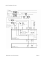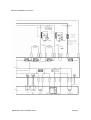
1
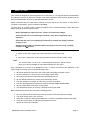
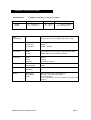
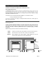
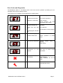
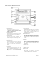
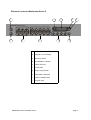
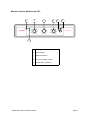
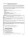
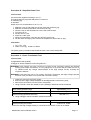
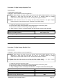
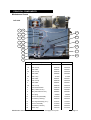
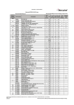
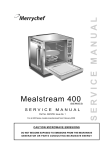
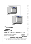
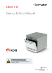
S E R V I C E
M A N U A L
For all Mealstream models manufactured from January 2001
Part No. 32Z3387 Issue No.2
SERVICE MANUAL
Mealstream
CAUTION MICROWAVE EMISSIONS
DO NOT BECOME EXPOSED TO EMISSIONS FROM THE MICROWAVE
GENERATOR OR PARTS CONDUCTING MICROWAVE ENERGY
Mealstream Ovens 32Z3387 Issue 2
Page 1
Table of Contents
Safety Code...........................................................................3
Product Specifications ...........................................................4
Installation Instructions ..........................................................5
Error Codes and Diagnostics.................................................6
Main Features........................................................................7
Electronic Controls ................................................................8
Manual Controls ....................................................................9
A – Power Output Testing to EN 60335-2-90:1996 .............10
B - Power Output Testing ....................................................11
C - Power Transformer Test ................................................11
D - High Voltage Capacitor Test..........................................12
E - High Voltage Rectifier Test ............................................12
Principal components LHS ..................................................13
Principal components RHS..................................................14
Principal components Top ...................................................15
Principal components Roof, heater and door ......................16
Principal components ( not shown in main views ) .............17
Input wiring ..........................................................................18
Interlock Operation ..............................................................19
Electronic Control Panel Assembly .....................................20
Manual Controls Panel Assembly........................................21
Membrane Panel Circuit ......................................................22
Complete Spare Part Listing.......................................... 23-24
Electrical Diagram ........................................................ 25-26
Electrical Diagram ........................................................ 27-28
Manual corrections and modifications .................................29
Merrychef Limited,
Station Road West,
Ash Vale, Aldershot
Hampshire GU12 5XA
United Kingdom
Tel: +44 (0)1252 371000 Fax: +44 (0)1252 371007
Internet address: http://www.merrychef.co.uk
E-mail: [email protected] or [email protected]
Mealstream Ovens 32Z3387 Issue 2
Page 2
SAFETY CODE
This manual is designed to assist engineers who have been on a recognised product familiarisation
and training course run by Merrychef Limited. It has been prepared to offer technical guidance for the
Merrychef Mealstream range of Combination Microwave Ovens.
Please remember that it is wiser not to attempt a service task if you are unsure of being able to
complete it competently, quickly, and above all safely.
To avoid injury to yourself, and to protect the appliance from possible damage, please follow this
Safety Code when servicing these ovens.
Before attempting to repair the oven, check it for microwave leakage.
Check that the oven is not emitting microwaves, even when supposedly not in
operation.
Check that the oven is not operating continuously, whether the display indicates
cooking or not.
Always discharge the HT capacitors before working on the oven using a suitably
insulated 10 MΩ Resistor
Before removing the rear cover from the oven, do all of the following:
• Switch off the mains supply and remove the plug from the wall socket.
or
• If the oven is hard wired, ensure that the power is turned off at the isolator switch.
Note:
The On/Off switch on the oven is not adequate protection against electric
shock, as it does not isolate all of the internal wiring from the mains.
Upon completion of a service on a Mealstream oven, or before reconnecting the appliance to the
mains supply for testing, check all of the following points:
•
•
•
•
•
•
•
•
All internal electrical connections are correct (see wiring diagram Pages 23-24).
All wiring insulation is correct and is not touching a sharp edge.
All Earth connections are electrically and mechanically secure.
All door safety interlocks are secure and mechanically sound.
The door operation is smooth, and the arms run freely in the slots.
The door activates all three of the door interlock switches in the correct order.
All fuse-holder safety covers are correctly fitted.
The temperature sensor is correctly connected to the Power PCB.
Before finishing the service call, recheck the following points:
•
•
•
•
All of the electronics are functioning correctly, and all of the touch pads are working.
The power output of the oven is correct.
Microwave emission is below permissible limit - 5 mW/cm² (see BS EN 60335-2-90:1998).
Oven has correct 50mm air gap all round and 50mm above.
Air flow should not be restricted.
Mealstream Ovens 32Z3387 Issue 2
Page 3
PRODUCT SPECIFICATIONS
Model Number:
Model prefix
CTM3
CTM5.5
+ Voltage + Frequency + Current + Controls
Voltage
Frequency
Control Type
50 = 50 Hz
60 = 60 Hz
5 = Series 5 controls
CD2 = Manual controls
22 = 220-230V a.c.
24 = 230-240V a.c
Power
Requirements
230-240V ac 50 Hz 13.0A Single Phase 2 Wire + Earth.
220-230V ac 50 Hz 14.2A Single Phase 2 Wire + Earth.
Power Output
Microwave 100%
Convection
Combination
1425W (IEC 705)
2500W
1425W + 2500W
External
Dimensions
Height
Width
Depth
640mm (Plus 50 mm minimum clearance above)
710mm (Plus 50 mm minimum clearance each side)
630mm (Plus 50 mm clearance behind)
Internal
Dimensions
Height
Width
Depth
Capacity
260 mm
490 mm
360 mm
45.86 litres (1.62 ft³)
Weight
Nett
Gross packed
90 kg
106 kg
Construction
Cavity
Casework
304 Stainless Steel
Settings
Microwave
Temperature
Timer
100%,75%,50%,25%, Convection only
Off, 150°, 175°, 200°, 225°, 250°C
Up to 30 minutes
Up to 3 cooking stages of up to 30 minutes each Programmed
(Series 5)
Mealstream Ovens 32Z3387 Issue 2
Page 4
INSTALLATION INSTRUCTIONS
Installation Instructions for Mealstream Combination Ovens
Power Supply Requirements
The Mealstream Series should be connected to a suitable electricity supply, which can cope
with the switching-on surge that occurs with certain types of catering equipment, such as
microwaves. Because of this requirement, we strongly recommend that a separate, suitably
rated supply is installed for the oven.
The supply for the oven should be fitted with a Type "C" circuit breaker, rated at:
30 Amp for Mealstream (all models)
If the oven is hard-wired to the supply, a double-pole isolator switch with a contact gap of at
least 3 mm should be fitted.
Positioning the Oven
In order to maintain adequate ventilation for air intake and exhaust, and to allow access for
cleaning filters, you must allow a minimum of 50 mm clearance at the sides and rear of the
oven, and at least 50 mm above. Air intake temperature should not exceed 35°C - excessive
temperature will lead to reduced operating duty cycle or premature ageing of internal
components.
Failure to comply with these conditions will invalidate the warranty.
NEVER
Install an oven above fryers, grills, griddles or any other major heat source.
NEVER
Stack machines on top of each other - always use a double stand.
ALWAYS
Place containers in the cavity carefully - impact damage may chip the
vitreous enamel coating on the runners and baffle plate.
50mm
50mm
50mm
Mealstream Ovens 32Z3387 Issue 2
50mm
350mm
Page 5
Error Codes and Diagnostics
The Mealstream Series 5 will identify some of the most common problems by flashing an error
message code in the time display window.
These are the error messages, and suggestions for repairing them.
1
Door not fully shut.
Close door fully.
2
Possible electrical fault
Door switch inoperative.
3
Magnetron overheating.
Check air filters.
Check location, air inlet
temperature and air filters.
1
No time has been set.
Set a time.
2
3
Invalid time has been Set a valid time.
set.
Use call-back to check program.
Invalid program has been
set.
1
Oven not heating up.
Check heater fuse.
2
Possible Heater fault.
Confirm
circuit.
1
Oven Cavity overheating. Confirm heater
operating.
Check sensor
1
Oven is not at correct Remove food.
temperature to start Allow oven to reach correct
program.
temperature.
Oven control
overheating.
Service indicator
Mealstream Ovens 32Z3387 Issue 2
area
operation
of
heater
relay
is
is Check air filters.
Check axial fan.
Check installation for hot air
intake.
Indicates that the oven has
overheated previously
Page 6
Main Features: Mealstream Ovens
a
b
b
c
f
d
g
j
e
k
k
i
h
a On/Off SWITCH
This is used to turn the oven On or Off.
IT DOES NOT ISOLATE INTERNAL WIRING
FROM THE MAINS SUPPLY.
b STEAM OUTLET
Allows steam and excess pressure to escape
from the oven cavity. It must be kept clear.
c OVEN CAVITY
The oven cavity is mainly constructed from
stainless steel panels. It must be kept clean.
d BAFFLE PLATE
Forms the inside rear of the oven and covers
the hot air circulation fan. This must be
cleaned on a regular basis, and kept free of
debris.
f HOT AIR FAN
Situated behind the baffle plate, and circulates
the hot air through the baffle plate, over the
heating element, and around the edge of the
baffle plate back into the cavity.
g RATING PLATE
The rating plate is situated on the rear of the
oven, and states the Model, Serial Number,
Electrical Ratings and Manufacturers telephone
number.
h DOOR
The door consists of a thermally insulated inner
section, and an additional air gap provided by a
twin skinned door front to lower the surface
temperature.
i DOOR SEAL
e RUNNERS
These are mounted on each side of the oven
cavity to support the rectangular racks or oven
trays and are for use in Convection mode
only.
Mealstream Ovens 32Z3387 Issue 2
j MAINS LEAD
k AIR FILTER
Main intake for cooling air for internal
components. Must be clear of obstructions.
Page 7
Electronic controls: Mealstream Series 5
j
b
a
c
d
mealstream
1
P
0
150
175
1
2
3
4
5
C
200
225
250
6
7
8
9
0
i
g
h
a
Stage LED's
b
Program & Time Display
c
Service Indicator
d
Air Filter Block Indicator
e
Convection Pad
f
Power Pads
g
Time / Precept Pads
h
Temperature Set Pads
i
Cancel / Callback Pad
j
Program Pad
Mealstream Ovens 32Z3387 Issue 2
2
3
100%
75%
f
50%
25%
e
Page 8
Manual controls: Mealstream CD2
a
b
b
TEMP °C
POWER %
b
TIME
merrychef
c
d
START
Mealstream CD
2
e
a
Power Neon ( Amber )
b
Control Knob
c
Start Push button
d
Cook cycle Neon ( Red )
e
Heater Neon ( Amber )
Mealstream Ovens 32Z3387 Issue 2
Page 9
Procedure A - Power Output Test in accordance with
BS EN 60335-2-25:1996 Annex AA
This test is given in the BSI test standard for microwave ovens. It is reproduced below - not so that
you can follow it, but to show you why it is impractical in normal conditions. A simplified procedure,
which gives a good approximation to the BSI power output, is given in Procedure B which follows.
Note: This test can only be carried out on a COLD oven. If the oven has been operating, even for
only a few seconds, the power given will be lower than the oven rating. This test must also be carried
out at a stable voltage - the voltage in most kitchens varies considerably even within the period of the
test. If the oven has been operating, go to Procedure B.
You will need:
A thermometer capable of reading to ±0.1°C.
A cylindrical borosilicate glass container, 190 mm diameter, with a wall thickness of
3 mm or less.
A calculator.
A set of scales capable of reading 1 kg to an accuracy of ± 1 g.
A glass or plastic stirrer.
A jug capable of holding over 1 litre of water.
Drinkable water which is at a temperature of 10°C ± 1°C.
A “Variac” or similar variable transformer capable of supplying the oven to ensure a
stable voltage.
WARNING: The Borosilicate Glass container has thin walls and is therefore fragile
- take care not to break it during use.
Method
A cylindrical container of borosilicate glass is used for the test. It has a maximum thickness of
3 mm, an external diameter of approximately 190 mm and a height of approximately 90 mm. The
mass of the container is determined.
At the start of the test, the oven and the empty container are at ambient temperature. Potable water
having an initial temperature of 10°C ± 1°C is used for the test. The temperature of the water is
measured immediately before it is poured into the container.
A quantity of 1000 g ± 5 g of water is added to the container and its actual mass obtained. The
container is then immediately placed in the middle of the oven shelf which is in its lowest normal
position. The appliance is supplied at rated voltage and operated at the maximum power setting. The
time for the water temperature to attain 20°C ± 2°C is measured. The oven is then switched off and
the final water temperature is measured within 60s.
NOTES:
1 The water is stirred before its temperature is measured.
2 Stirring and measuring devices are to have a low heat capacity.
The microwave power output is calculated from the formula:
P=
4.187 MW (T2-T1) + 0.55 MC (T2-T0)
t
where
P
MW
MC
T0
T1
T2
t
is the microwave power output, in watts;
is the mass of the water, in grams;
is the mass of the container, in grams;
is the ambient temperature, in °C;
is the initial temperature of the water, in °C;
is the final temperature of the water, in °C;
is the heating time in seconds, excluding the magnetron filament heat-up time.
Mealstream Ovens 32Z3387 Issue 2
Page 10
Procedure B - Simplified Power Test
You will need:
A thermometer capable of reading to ±0.1°C.
A Polypropylene tray approximately 200 mm x 200 mm.
A measuring jug.
A calculator.
Water which is at a temperature of 10°C ± 2°C.
1
2
3
4
5
6
7
8
Measure 1 litre of cold water into the tray using the measuring jug.
Measure the water temperature, and record it as T[s].
Place the tray on the turntable in the oven and close the door.
Turn the oven on.
Set the timer to 1:02.
Press the “100%” pad.
When the oven bleeps, open the door and remove the tray.
Stir the water thoroughly, and measure its temperature. Record this as T[e].
Calculation:
1 T[r] = T[s] - T[e].
2 Power = 70 x T[r]. Power is in Watts.
The power given by the above test should be within ±10% of the rated power.
Procedure C - Power Transformer Test
You will need:
A Digital Multi-meter (D.M.M.)
A Megger or similar resistance meter using 500V d.c.
WARNING: High voltages and large currents are present at the secondary winding and filament
winding of the Power Transformer. It is very dangerous to work near this part when the oven is
on. NEVER make any voltage measurements at the High Voltage circuits, including the
magnetron filament.
WARNING: Even when the oven is not cooking, the Power Transformer has High Voltages present
because of the Soft Start circuit. Isolate the oven before testing.
1
2
3
4
Isolate the oven from the mains supply.
Ensure that the High Voltage Capacitor is discharged before commencing work.
Remove all connections from the Power Transformer.
Using a D.M.M., check the resistance of the windings. Results should be as follows:
Mains winding (between tags)
Approximately 1.1 Ω
High Voltage winding (between tag & chassis)
Approximately 60 Ω
Filament winding (between terminals)
Less than 1 Ω
5 Using a Megger, test the insulation resistance between:
Primary winding and chassis
Pass if over 10 MΩ
Filament winding and chassis
Pass if over 10 MΩ
One end of the High Voltage winding is connected to the chassis, so this is not tested.
Mealstream Ovens 32Z3387 Issue 2
Page 11
Procedure D - High Voltage Capacitor Test
You will need:
A Digital Multi-meter (D.M.M.)
A Megger or similar resistance meter using 500V d.c.
WARNING: High voltages and large currents are present at the High Voltage Capacitor. It is very
dangerous to work near this part when the oven is on. NEVER make any voltage
measurements at the High Voltage circuits, including the magnetron filament .
WARNING: Even when the oven is not cooking, the High Voltage Capacitor has High Voltages
present because of the Soft Start circuit. Isolate the oven before testing.
1
2
3
4
Isolate the oven from the mains supply.
Ensure that the High Voltage Capacitor is discharged before commencing work.
Remove all connections from the High Voltage Capacitor.
Using a D.M.M., check for continuity between the terminals & compare results with table.
Between Terminals
Between Terminals and Case
Pass if approximately 10 MΩ
Pass if open circuit
5 Using a Megger, test the insulation resistance between the terminals and the case.
Between Terminals and Case
Pass if over 100 MΩ
Procedure E - High Voltage Rectifier Test
You will need:
A Megger or similar resistance meter using 500V d.c.
WARNING: High voltages and large currents are present at the High Voltage Rectifier. It is very
dangerous to work near this part when the oven is on. NEVER make any voltage
measurements at the High Voltage circuits, including the magnetron filament .
WARNING: Even when the oven is not cooking, the High Voltage Rectifier has High Voltages
present because of the Soft Start circuit. Isolate the oven before testing.
1
2
3
4
Isolate the oven from the mains supply.
Ensure that the High Voltage Capacitor is discharged before commencing work.
Remove all connections from the High Voltage Rectifier.
Using the Megger, test for continuity in both directions. Compare results with following table.
Open Circuit both ways
FAIL
Conducts one way only
PASS
Short Circuit both ways
FAIL
Conducts one way, leaks the other
FAIL
Mealstream Ovens 32Z3387 Issue 2
Page 12
PRINCIPAL COMPONENTS
Mealstream Ovens
Left side
1
1A
2
2A
3
3A
59
4
4A
13
5
5A
12
14
6
11
7
10
8
9
No
Description
SERIES 5
CD²
1
Fuse holder
30Z0231
30Z0231
1A
Fuse 10 amp
30Z0168
30Z0168
2
Fuse holder
30Z0231
30Z0231
2A
Fuse 10 amp
30Z0168
30Z0168
3
Fuse holder
30Z0285
30Z0285
3A
Fuse 1 amp
311008
311008
4
Fuse holder
30Z0231
30Z0231
4A
Fuse 13 amp
30Z0168
30Z0168
5
Fuse holder
30Z0231
30Z0231
5A
Fuse 13 amp
30Z0168
30Z0168
6
Mains terminal block
31Z0149
31Z0149
7
Filter ( Heater circuit )
30Z0997
30Z0997
8
Filter ( Microwave circuit )
30Z0997
30Z0997
9
Door spring
520000
520000
10
Door arm stop assembly
11C0279
11C0279
11
Microswitch ( Primary )
30Z0240
30Z0240
12
Door hinge assembly ( LH )*
11C0167
11C0167
13
Door arm assembly
11C0300
11C0300
14
Microswitch ( Monitor )
30Z0240
30Z0240
59
Rubber stop
31Z1150
31Z1150
Mealstream Ovens 32Z3387 Issue 2
* See page 16 for parts
Page 13
Principle components:
Right side
22
21
15
20
16
No
17
18
Description
19
SERIES 5
CD²
15
Door arm assembly
11C0300
11C0300
16
Door hinge assembly ( RH )*
11C0166
11C0166
17
Microswitch ( Secondary )
30Z0240
30Z0240
18
Door arm stop assembly
11C0279
11C0279
19
Door spring
520000
520000
20
Steam pipe
790046
790046
21
Steam vent guard
790061
790061
22
Temperature sensor
50E123
50E123
*See page 16 for parts
Mealstream Ovens 32Z3387 Issue 2
Page 14
Principle components:
Top view
60
61
23
23
24
24
25
25
26
26
27
27
28
No
Description
SERIES 5
62
CD²
23
Magnetron
30Z0264
30Z0264
24
Resistor 470 R
31Z0121
31Z0121
25
HT diode
30Z0246
31Z0246
26
Capacitor 1.1 µf
30Z0861
30Z0861
27
Transformer
30Z0992
30Z0992
28
Twin blower motor
310110
310110
60
25mm OD Flexible conduit
314402
314402
61
20mm OD Flexible conduit
314401
314401
62
Capacitor clip
31Z0175
31Z0175
Mealstream Ovens 32Z3387 Issue 2
Page 15
Principle components:
Door, roof & heater element
67
68
72
69
71
71
No
Description
CTM5.5
CD2
67
Stirrer glass
40C0954
40C0954
68
Heater element
40C0948
790063
69
Element cover plate
790047
790047
70
Baffle ( 2 No. )
11C0311
11C0311
71
Door seal kit
11C0261
11C0261
72
Door choke
790007
790007
Mealstream Ovens 32Z3387 Issue 2
Page 16
Principle components: ( not shown in main views )
Door hinge assembly ( Left hand shown )
No.
All models
49
Right Hand Assembly
11C0166
50
Left Hand Assembly
11C0167
51
Pin
52
Roller
53
Bolt
101825
54
Nut
80X7003
55
LH Hinge bracket
790024
56
RH Hinge bracket (not shown)
790025
No.
Description
Series 5
57
No.
58
52
51
55
790027
40C0752
Hot air motor
Description
Stirrer motor assembly
Mealstream Ovens 32Z3387 Issue 2
11C0312
54
53
CD2
11C0161
All models
11C0162
Page 17
INPUT WIRING DETAILS
6
Green/Yellow
Blue
Brown
46
48
No
47
Description
SERIES 5
CD²
6
Mains Terminal Block
31Z0149
31Z0149
46
Cable Gland
31Z1070
31Z1070
47
Gland Nut
31Z1082
31Z1082
48
Mains Cable 3 Core
31Z0148
31Z0148
Mealstream Ovens 32Z3387 Issue 2
Page 18
Door Interlock Operation
The door on the Mealstream oven is monitored by three microswitches. These are used in the
conventional “Primary, Secondary and Monitor” switch arrangement shown below.
The switches operate as follows:
Door Interlock Arrangement
Secondary switch
L
17
Primary switch 11
Power Out
Power In
N
Monitor switch 14
1. Primary Interlock [ 11 , Bottom left-hand ]
The Primary switch will cut off the microwave emissions from the oven when
the door is opened by breaking the mains supply circuit to the transformers.
2. Monitor [ 14 ,Top left-hand Side ] and
Secondary Interlock [ 17 , Bottom right-hand ] Switches.
Operate simultaneously.
The Monitor switch will produce a short circuit across the mains supply if the
Primary interlock switch is faulty, thus blowing the microwave fuse and
rendering the oven inoperative.
The Secondary interlock switch will cut off the microwave emission if the
other switches have failed.
Note:
If operation of the Monitor switch has caused the Microwave Fuse to blow,
the Primary and Monitor microswitches must be changed, as they may have
been damaged by the high short-circuit currents involved.
Mealstream Ovens 32Z3387 Issue 2
Page 19
Electronic Control Panel Assembly: Mealstream Series 5
34
33
29
32
31
30
No
Description
Series 5
29
On/Off Switch
30Z0503
30
Control Panel Assembly
11C0294
31
Logic Board
11C0213
32
Relay Board
11C0212
33
AC Ribbon connector
11M0116
34
DC Ribbon connector
11M0117
Mealstream Ovens 32Z3387 Issue 2
Page 20
Manual Control Panel Assembly: Mealstream CD²
38
39
35
40
40
29
38
44
41
29
38
45
44
41
38
No
Description
CD²
35
PCB Assembly
11C0295
36
ac voltage connector 6 way
11M0116
37
dc voltage connector 10 way
11M0117
38
Red Neon
39
Timer
30Z0991
40
Potentiometer 5k
40C0892
41
Amber Neon
316031
29
On /off switch
30Z0503
43
Panel assembly
11C0309
44
Pushbutton
31Z0349
45
Timer knob
11C0406
Mealstream Ovens 32Z3387 Issue 2
316030
Page 21
Membrane Panel Circuit
You will need:
A Digital Multi-meter (D.M.M.)
1.
2.
3.
4.
Isolate the oven from the mains supply.
Remove the Logic Assembly from the Control Panel Housing.
Unplug the membrane “tail” from the Logic PCB Assy.
Using a D.M.M., check for continuity between the correct terminals when the
pads are pressed.
5. When the panel has been tested, re-assemble and re-test the control housing.
1
Mealstream Ovens 32Z3387 Issue 2
10
Page 22
Part Number Identification Chart: Mealstream series ovens
No
Description
SERIES 5
Part No
CD²
Page No
Part No
Page No
1
Fuse holder
30Z0231
13
30Z0231
13
1a
Fuse 10 amp
30Z0168
13
30Z0168
13
2
Fuse holder
30Z0231
13
30Z0231
13
2a
Fuse 10 amp
30Z0168
13
30Z0168
13
3
Fuse holder
30Z0285
13
30Z0285
13
3a
Fuse 1 amp
311008
13
311008
13
4
Fuse holder
30Z0231
13
30Z0231
13
4a
Fuse 13 amp
30Z0168
13
30Z0168
13
5
Fuse holder
30Z0231
13
30Z0231
13
5a
Fuse 13 amp
30Z0168
13
30Z0168
13
6
Mains terminal block
31Z0149
13/18
31Z0149
13/18
7
Filter ( Heater circuit )
30Z0997
13
30Z0997
13
8
Filter ( Microwave circuit )
30Z0997
13
30Z0997
13
9
Door spring
520000
13
520000
13
10
Door arm stop assembly
11C0279
13
11C0279
13
11
Microswitch ( Primary )
30Z0240
13
30Z0240
13
12
Door hinge assembly ( LH )
11C0167
13
11C0167
13
13
Door arm assembly
11C0300
13
11C0300
13
14
Microswitch ( Monitor )
30Z0240
13
30Z0240
13
15
Door arm assembly
11C0300
14
11C0300
14
16
Door hinge assembly ( RH )
11C0166
14
11C0166
14
17
Microswitch ( Secondary )
30Z0240
14
30Z0240
14
18
Door arm stop assembly
11C0279
14
11C0279
14
19
Door spring
520000
14
520000
14
20
Steam pipe
790046
14
790046
14
21
Steam vent guard
790061
14
790061
14
22
Temperature sensor
50E123
14
50E123
14
23
Magnetron
30Z0264
15
30Z0264
15
24
Resistor 470 R
31Z0121
15
31Z0121
15
25
HT diode
30Z0246
15
31Z0246
15
26
Capacitor 1.1 µf
30Z0861
15
30Z0861
15
27
Transformer
30Z0992
15
30Z0992
15
28
Twin blower motor
30Z1067
15
30Z1067
15
Mealstream Ovens 32Z3387 Issue 2
Page 23
Part Number Identification Chart: Mealstream series ovens
No
Description
SERIES 5
CD²
Part No
Page No
Part No
Page No
29
On/Off Switch
30Z0503
20
30
Control Panel Assembly
11C0310
20
———
———
31
Logic Board
11C0213
20
———
———
32
Relay Board
11C0212
20
———
———
33
AC Ribbon connector
11M0116
20
———
———
34
DC Ribbon connector
11M0117
20
———
———
35
PCB Assembly
———
———
11C0295
21
36
ac voltage connector 6 way
———
———
11M0116
21
37
dc voltage connector 10 way
———
———
11M0117
21
38
Red Neon
———
———
316030
21
39
Timer
———
———
30Z0991
21
40
Potentiometer 5k
———
———
40C0892
21
41
Amber Neon
———
———
316031
21
43
Panel assembly
———
———
11C0309
21
44
Pushbutton
———
———
31Z0349
21
45
Timer knob
———
———
11C0406
21
46
Cable Gland
31Z1070
18
31Z1070
18
47
Gland Nut
31Z1082
18
31Z1082
18
48
Mains Cable 3 Core
31Z0148
18
31Z0148
18
49
Right Hand Assembly
11C0166
17
11C0166
17
50
Left Hand Assembly
11C0167
17
11C0167
17
51
Pin
790027
17
790027
17
52
Roller
40C0752
17
40C0752
17
53
Bolt
101825
17
101825
17
54
Nut
80X7003
17
80X7003
17
55
LH Hinge bracket
790024
17
790024
17
56
RH Hinge bracket
790025
17
790025
17
57
Hot air motor
11C0312
17
11C0161
17
58
Stirrer motor assembly
11C0162
17
11C0162
17
59
Rubber stop
31Z1150
13
31Z1150
13
60
25mm OD Flexible conduit
314402
15
314402
15
61
20mm OD Flexible conduit
314401
15
314401
15
62
Capacitor clip
31Z0175
15
31Z0175
15
67
Stirrer glass
40C0954
16
40C0954
16
68
Heater element
40C0948
16
790063
16
69
Element cover plate
790047
16
790047
16
70
Baffle ( 2 No. )
11C0311
16
11C0311
16
71
Door seal kit
11C0261
16
11C0261
16
72
Door choke
790007
16
790007
16
Mealstream Ovens 32Z3387 Issue 2
Page 24
CIRCUIT DIAGRAM: Series 5 Part 1
Mealstream Ovens 32Z3387 Issue 2
Page 25
CIRCUIT DIAGRAM: Series 5 Part 2
Mealstream Ovens 32Z3387 Issue 2
Page 26
CIRCUIT DIAGRAM: CD2 Part 1
Mealstream Ovens 32Z3387 Issue 2
Page 27
CIRCUIT DIAGRAM: CD2 Part 2
Mealstream Ovens 32Z3387 Issue 2
Page 28
Manual Corrections and Modifications
Whilst every effort has been made to ensure that the information contained in this manual is
accurate and complete, if you believe that an error has been made, or if you have any
suggestions for how the manual could be improved, please fill in and return this form. A review of
any forms returned will be made on a regular basis, and the manual will be updated if required.
Name
Address
Page on which error occurs (if applicable) - Mealstream
Description of error
Suggestion for improvement to manual
Please return this form to:
Engineering Department
Merrychef Ltd
Station Road West
Ash Vale
Aldershot
Hampshire
GU12 5XA
Or Fax it on:
+44 (0) 1252 371007
Mealstream Ovens 32Z3387 Issue 2
Page 29