1
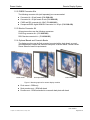
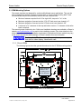
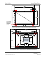
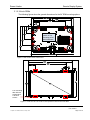
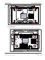
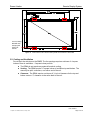
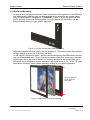
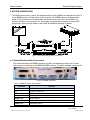
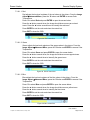
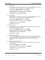
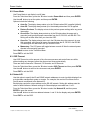
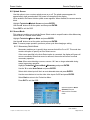
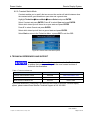
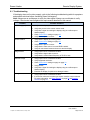
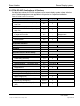
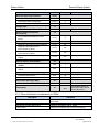
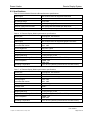
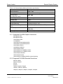
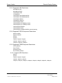
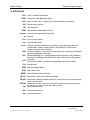
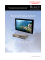
ELECTRONIC REVISION CONTROLLED Document Number 105134 Rev A Rosen Aviation Remote Display System Technical Manual, Remote Display System © 2011 by Rosen Aviation, LLC All Rights Reserved The information contained herein is proprietary to Rosen Aviation, LLC. No part of this publication may be reproduced, transmitted, transcribed, stored in a retrieval system, or translated into any language in any form by any means without the written authorization from Rosen Aviation, LLC, except as allowed under copyright laws. Disclaimer of Liability The information contained in this document is subject to change without notice. Because we are continuously improving and adding features to our products, Rosen Aviation, LLC reserves the right to change specifications without prior notice. Rosen Aviation, LLC shall not be liable for technical or editorial errors or omissions contained herein. Rosen Aviation, LLC 1020 Owen Loop South Eugene, OR 97402 541.342.3802 888.668.4955 Fax: 541.342.4912 www.rosenaviation.com Document Number: 105134 Template: 4.2.3-6-FM; Revision A; 16 May, 2005 Revision: Date: 08/08/11 A Page 2 of 39 Rosen Aviation Remote Display System Contents 1. INTRODUCTION .................................................................................................................5 1.1. Remote Display Modules ..............................................................................................5 1.2. Additional System Materials..........................................................................................5 1.2.1. IR Remotes ...................................................................................................................... 5 1.2.2. RMEB Connector Kits ....................................................................................................... 6 1.2.3. Monitor Connector Kit ....................................................................................................... 6 1.2.4. Optional Bezels and Cosmetic Backs ............................................................................... 6 2. VIDEO INPUTS ...................................................................................................................7 3. INSTALLATION GUIDELINES ...........................................................................................7 3.1. RDM Mounting Options.................................................................................................8 3.1.1. 19-inch RDMs ................................................................................................................... 8 3.1.2. 24-inch RDMs ................................................................................................................. 10 3.1.3. 26-inch RDMs ................................................................................................................. 11 3.2. Cooling and Ventilation ...............................................................................................12 3.3. Bezels and Mounting ..................................................................................................13 4. SYSTEM CONNECTIONS ................................................................................................14 4.1. Remote Electronics Box Connectors ..........................................................................14 4.2. Pinout Connections .....................................................................................................15 5. RS-232 AND RS-485 CONTROL INPUTS........................................................................15 6. INITIAL POWER UP .........................................................................................................16 7. OSD MENU OPTIONS ......................................................................................................16 7.1. Exit ..............................................................................................................................17 7.2. User Menu ..................................................................................................................17 7.2.1. Backlight ......................................................................................................................... 17 7.2.2. Aspect Ratio ................................................................................................................... 18 7.2.3. Scheme .......................................................................................................................... 18 7.2.4. Source ............................................................................................................................ 19 7.2.5. Auto Adjust ..................................................................................................................... 19 7.3. Image Adjust ...............................................................................................................19 7.3.1. Scheme .......................................................................................................................... 20 7.3.2. Brightness ...................................................................................................................... 20 7.3.3. Contrast .......................................................................................................................... 20 7.3.4. Saturation ....................................................................................................................... 20 7.3.5. Hue................................................................................................................................. 21 7.3.6. Sharpness ...................................................................................................................... 21 7.3.7. Reset Scheme ................................................................................................................ 21 7.3.8. Image Adjust Advanced (Submenu) ............................................................................... 22 7.4. Info ..............................................................................................................................25 Document Number: 105134 Template: 4.2.3-6-FM; Revision A; 16 May, 2005 Revision: Date: 08/08/11 A Page 3 of 39 Rosen Aviation Remote Display System 8. TECHNICIAN MENU .........................................................................................................26 8.1. Advanced Technician Menu........................................................................................27 8.1.1. Factory Reset ................................................................................................................. 27 8.1.2. Viewing Angle ................................................................................................................. 27 8.1.3. Comp/RGB 1 .................................................................................................................. 28 8.1.4. Comp/RGB 2 .................................................................................................................. 28 8.1.5. 3D Comb Filter ............................................................................................................... 28 8.1.6. Composite SIG (Signal) .................................................................................................. 28 8.1.7. AGC (Automatic Gain Control) ........................................................................................ 28 8.2. Power Mode................................................................................................................29 8.3. OSD Timeout ..............................................................................................................29 8.4. Network ID ..................................................................................................................29 8.5. Splash Screen ............................................................................................................30 8.6. Source Mode ..............................................................................................................30 8.6.1. Momentary Switch Mode ................................................................................................ 30 8.6.2. Constant Switch Mode .................................................................................................... 31 9. TECHNICAL REFERENCES AND SUPPORT .................................................................31 9.1. Troubleshooting ..........................................................................................................32 9.2. RTCA DO-160F Qualifications for Displays ................................................................33 9.2.1. Other Certification Considerations for RDMs .................................................................. 34 9.3. Specifications..............................................................................................................35 9.3.1. Supported DVI/HDMI Graphic Resolutions ..................................................................... 36 9.3.2. Supported DVI/HDMI Standard Resolutions ................................................................... 36 9.3.3. Supported VGA Resolutions ........................................................................................... 37 9.3.4. Supported YPbPr/Component Resolutions ..................................................................... 37 9.3.5. Supported CVBS/Composite Resolutions ....................................................................... 37 10. DEFINITIONS..................................................................................................................38 11. REVISION HISTORY ......................................................................................................39 Document Number: 105134 Template: 4.2.3-6-FM; Revision A; 16 May, 2005 Revision: Date: 08/08/11 A Page 4 of 39 Rosen Aviation Remote Display System 1. INTRODUCTION Rosen’s Remote Display System consists of an ultra-thin remote display monitor and a remote electronics box. The remote electronics design provides more mounting options because the video processing electronics box can be located up to 50 feet from the display. The high-definition display monitors are available in a range of sizes and mounting options that allow customers to configure a system that fits their aircraft’s cabin interior. This manual provides general instructions about how to install all models of the Remote Display System onto your aircraft. It contains everything you need to know to wire the components and confirm that the system is functioning correctly. The model numbers listed are for reference purposes only. A wider range of specialty models is available. For more information about a remote display system, please contact Rosen Sales or Technical Support. Note: Only trained and qualified personnel should perform installation and service. 1.1. Remote Display Modules The Remote Monitor Electronics Box (RMEB) will operate one Remote Display Module (RDM), regardless of the size. Remote Display Modules are available in these sizes and configurations: 19” monitor – available in flush, semi proud, and proud mounts 24” monitor – available in flush, semi proud, and proud mounts 26” monitor – available in flush and semi proud mounts 1.2. Additional System Materials Documentation for the Rosen Remote Display System is available on the Rosen website at www.rosenaviation.com. Outline & Installation Drawings for Remote Monitor Electronics Box 0700-1xx series Outline & Installation Drawings for each size RDM, bezel, and cosmetic back Technical Manual From the Rosen Aviation home page, select the Products tab and browse by product category. Please contact Technical Support if you cannot find the drawing you need. 1.2.1. IR Remotes The RMEB provides 5V @100mA output to power an external IR receiver. The remote monitors do not have a built-in IR sensor. The following options (sold separately) enable remote inputs with the Remote Display System and adjust the on-screen display (OSD) settings: External IR Receiver (P/N 0500-006) HD Monitors IR kit (P/N 0500-023) Universal color display remote control (P/N 0500-020) Note: For directions on operating the optional universal remote control, refer to the User’s Guide enclosed with the remote. Document Number: 105134 Template: 4.2.3-6-FM; Revision A; 16 May, 2005 Revision: Date: 08/08/11 A Page 5 of 39 Rosen Aviation Remote Display System 1.2.2. RMEB Connector Kits The following connector kits (sold separately) are recommended: Connector kit—26-pin female (P/N 0300-043) Connector kit—25-pin female D-sub (P/N 0300-052) CVBS and SDI connector kit—BNC (P/N 0300-051) Component/RGB, digital HDMI/DVI connector kit—25-pin (P/N 0300-029) 1.2.3. Monitor Connector Kit All remote monitors use the following connectors: RJ45 Plug connector kit—(P/N 0300-050) DB15 female connector kit— (P/N 0300-053) 1.2.4. Optional Bezels and Cosmetic Backs The display monitors can be flush mounted, mounted with a sleek bezel, or proudmounted between a bezel and cosmetic back plate, as shown below. Please contact Rosen Sales for bezel kit requirements. Flush mount Semi-proud mount Proud mount Figure 1 Mounting options for remote display modules Flush mount – RDM only Semi-proud mount – RDM with bezel Proud mount – RDM is attached to a cosmetic back plate with bezel Document Number: 105134 Template: 4.2.3-6-FM; Revision A; 16 May, 2005 Revision: Date: 08/08/11 A Page 6 of 39 Rosen Aviation Remote Display System 2. VIDEO INPUTS The Rosen Remote Display System enables viewers to watch high definition video signals in a variety of formats as well as standard video signals. The 0700-104 remote electronics box supplies the following video inputs; however, the available inputs on other models will vary. Two 3G-SDI inputs Two composite (CVBS) Two DVI inputs (HDMI) RGB & Component (YPbPr) - through the DVI connectors only Accepts inputs up to 1080p, VGA-WUXGA This unit can be controlled via an IR (infrared) remote interface, RS-232-based 7-button external controller (P/N 0300-408), or RS-485 external inputs. The display connects to 28VDC aircraft power and receives video through a video distribution amplifier or directly from video sources. 3. INSTALLATION GUIDELINES You can mount the RMEB in any orientation with a minimum of six #8 screws (three per flange). (Dimensions are in inches) Figure 2 Dimensions for the mounting holes Use care to prevent debris from entering the housing fan openings during installation. Document Number: 105134 Template: 4.2.3-6-FM; Revision A; 16 May, 2005 Revision: Date: 08/08/11 A Page 7 of 39 Rosen Aviation Remote Display System 3.1. RDM Mounting Options The remote monitors are designed for vertical wall/bulkhead mount applications. They can be flush mounted from the back, through an interior wall, or from the front mounting tabs. Proud mounted RDMs must be mounted from the front into the cosmetic back. Minimum fasteners required four 8-32 or eight 4-40; torqued to 7 ± 1 in-lbs. Maximum projection of screws into the 19” & 26” flush mount rear chassis is ¼” Maximum projection of screws into the 24” flush mount rear chassis is 3/8” A minimum of ½” clearance for the top and bottom vents or ½” clearance to the entire back is required. The manual groups monitors by size. Outline and Installation drawings are available on Rosen’s website www.rosenaviation.com to assist in the installation process. Pay close attention to the dimensions when considering installation requirements. Dimensions for some models may vary, so be sure to consult the latest drawings on Rosen’s website for more information. Touching the LCD with excessive force may leave pressure spots that show in video display. Handle with care. 3.1.1. 19-inch RDMs The following figures show the general dimensions for the 19” RDM mounting options. Use a minimum pattern of four mounting points #8-32 hardware Figure 3 Rear view of a 19” flush mount Document Number: 105134 Template: 4.2.3-6-FM; Revision A; 16 May, 2005 Revision: Date: 08/08/11 A Page 8 of 39 Rosen Aviation Remote Display System Four mounting tabs with two screws each 4-40 FHP screws Figure 4 Front view of a 19” flush or semi-proud mount from the front tabs Use a minimum pattern of four mounting points #8-32 hardware Figure 5 Rear view of the 19” cosmetic back (shown with chassis) for a proud mount Document Number: 105134 Template: 4.2.3-6-FM; Revision A; 16 May, 2005 Revision: Date: 08/08/11 A Page 9 of 39 Rosen Aviation Remote Display System 3.1.2. 24-inch RDMs The following figures show the general dimensions for the 24” RDM mounting options. Use a minimum pattern of four mounting points #8-32 hardware Figure 6 Rear view of a 24” flush mount Four mounting tabs with two screws each 4-40 FHP screws Figure 7 Front view of a 24” flush or semi-proud mount from the front tabs Document Number: 105134 Template: 4.2.3-6-FM; Revision A; 16 May, 2005 Revision: Date: 08/08/11 A Page 10 of 39 Rosen Aviation Remote Display System Use a minimum pattern of four mounting points #8-32 hardware Figure 8 Rear view of the 24” cosmetic back (shown with chassis) for a proud mount 3.1.3. 26-inch RDMs The following figures show the general dimensions for the 26” RDM mounting options. Use a minimum pattern of four mounting points #8-32 hardware Figure 9 Rear view of a 26” flush mount Document Number: 105134 Template: 4.2.3-6-FM; Revision A; 16 May, 2005 Revision: Date: 08/08/11 A Page 11 of 39 Rosen Aviation Remote Display System Four mounting tabs with two screws each 4-40 FHP screws Figure 10 Front view of a 26” flush or semi-proud mount from the front tabs 3.2. Cooling and Ventilation Do not block the side fans on the RMEB. The fan openings require a minimum of 4 square inches of free air ventilation – 2 square inches per side. The RDMs do not require any external forced-air cooling. Venting: The RDMs require 4.7 square inches of ventilation top and bottom. The area may be split, continuous, or at either end of the unit. Clearance: The RDMs require a minimum of ½ inch of clearance for the top and bottom vents or ½” clearance to the entire back of the unit. Document Number: 105134 Template: 4.2.3-6-FM; Revision A; 16 May, 2005 Revision: Date: 08/08/11 A Page 12 of 39 Rosen Aviation Remote Display System 3.3. Bezels and Mounting An optional semi-proud mount attaches a bezel to bosses around the perimeter of the RDM with wire retaining clips. Install the clips to mounting bosses on the bezel after any custom plating using the Bezel Retention Hardware kit (P/N 0500-021). Figure 11 shows the assembled wire clips on the back of the model 900-style bezel. For further dimensional information, see the Rosen assembly drawing for your specific application. Figure 11 Wire clip mounting boss assembly on bezel Separate installation instructions come with the hardware kit. The number of wire clips required will vary depending on the size of the bezel and RDM. To add a stylish, proud-mount option, attach a cosmetic back plate to the RDM chassis and then snap on the assembled bezel. Figure 12 shows an exploded view of the proud-mount assembly. Align the four tabs on the monitor with the four mounting brackets on the cosmetic back plate. Secure with two 4-40 fasteners in each tab/bracket, and torque screws to 7 ± 1 in-lbs. For further dimensional information, see the Rosen assembly drawing for your specific application. Mounting brackets on the cosmetic back plate. Figure 12 RDM proud-mount bezel assembly Document Number: 105134 Template: 4.2.3-6-FM; Revision A; 16 May, 2005 Revision: Date: 08/08/11 A Page 13 of 39 Rosen Aviation Remote Display System 4. SYSTEM CONNECTIONS The RDM receives power, control, and serialized video from the RMEB via connectors P3 and P4 on the RMEB from up to 50 feet away, as shown below. The RMEB outputs a serialized video signal via CAT6 cable from P4 and provides conditioned power and control to the RDM via a harness with DB15 connectors from P3. We suggest using shielded harnesses to improve EMI performance. See the wiring tables on the Outline & Installation drawings for details. Figure 13 Remote display system connections 4.1. Remote Electronics Box Connectors This section describes the RMEB connectors and their corresponding functions. All of these video inputs are functional on the 0700-104 RMEB; however, the inputs available vary by model. Figure 14 RMEB connectors Table 1 RMEB connectors and functions Connector Function P1 Communication for RS-232, RS-485, External IR control P2 Power in / Ethernet in P3 Conditioned power out to the monitor P4 Video signal out to the monitor 3G SDI 1 & 2 3G SDI video in DVI-I 1 & 2 HDMI / DVI / Component / RGB video in CVBS 1 & 2 Composite video in Document Number: 105134 Template: 4.2.3-6-FM; Revision A; 16 May, 2005 Revision: Date: 08/08/11 A Page 14 of 39 Rosen Aviation Remote Display System 4.2. Pinout Connections There are several ways to connect the remote display system to an aircraft’s entertainment system. Pay close attention to the pinout descriptions on the Outline and Installation drawings to assist in completing the wiring connections. Note: This display is for entertainment purposes only; connect to a non-critical power bus. 5. RS-232 AND RS-485 CONTROL INPUTS Inputs that control the RDMs can come from an IR, RS-232-based 7-button external controller (P/N 0300-408), or via a cabin management system using RS-232 or RS-485. The 0700-104 RMEB accepts the following commands: Table 2 RS-485 and RS-232 commands Control Description Power ON Turn the display on Power OFF Turn the display off Source Composite 1 Select composite 1 video input Source Composite 2 Select composite 2 video input Source HD-SDI 1 Select HD-SDI 1 video input Source HD-SDI 2 Select HD-SDI 2 video input Source VGA 1 Select analog VGA 1 video input Source VGA 2 Select analog VGA 2 video input Source DVI 1 Select DVI 1 video input Source DVI 2 Select DVI 2 video input Source YPbPr 1 Select YPbPr 1 component video input Source YPbPr 2 Select YPbPr 2 component video input Ping Address (RS-485 only) Used by master device to detect all devices attached to the network Exit Exit the menu OK/Enter Selects active option when OSD is active Control RS-232 7-button External Controller Command Set Power Toggles the display on or off Source Scrolls through enabled video inputs Menu/Select Displays OSD. Selects active option when OSD is active Left Navigate left through the OSD menu Right Navigate right through the OSD menu Up Navigate up through the OSD menu Down Navigate down through the OSD menu Document Number: 105134 Template: 4.2.3-6-FM; Revision A; 16 May, 2005 Revision: Date: 08/08/11 A Page 15 of 39 Rosen Aviation Remote Display System 6. INITIAL POWER UP Make sure that power is turned off and connect the following harnesses to the RMEB connectors: 1. Ensure positive ground connections on the RMEB housing and monitor chassis grounding lugs. 2. 3. 4. 5. Connect an external IR control or RS-232/RS-485 communication harness to P1. Connect 28VDC power to P2. Attach extra cabling length to the RDM DB 15 pigtail and connect to P3. Attach extra cabling length to the RDM RJ-45 RDM pigtail and connect to P4. Ground and strain relieve harnesses on RJ-45 connectors using the brackets provided. 6. Connect the available video inputs. 7. Apply power and wait for a signal on the RDM. The default setting for the 0700-104 RMEB is Auto On and the default source is SDI 1. Do not plug or unplug the display connector while power is applied. When cycling power, leave unit off for 20 seconds before restoring power. 7. OSD MENU OPTIONS The OSD contains screen settings and options in menus and informational readouts that display over the image, as shown below. Press MENU on the remote to open the Main Menu, as shown in Section 7.1. Press the ▲▼ buttons to navigate within the menu pages. Press the ►◄ buttons to navigate between the menu page, options, and values columns. The yellow highlighted area shows the currently selected option in the menu. Press ► to access the menu page options Press ▼ to access menu pages. The selected menu page is highlighted. Press ► to access the menu option values Figure 15 OSD menu options The available menu options will vary depending on which source signal is active. Press MENU to choose a setting or an option. Select the Back option to switch menu pages. Press EXIT to close the OSD and save settings. Document Number: 105134 Template: 4.2.3-6-FM; Revision A; 16 May, 2005 Revision: Date: 08/08/11 A Page 16 of 39 Rosen Aviation Remote Display System Note: The on-screen display will timeout and close automatically after no screen activity for a preset amount of time, which is adjustable on the Technician MenuOSD Timeout option. See Section 8.3, OSD Timeout, on page 29. 7.1. Exit Use Exit to close the OSD. When you press MENU on the remote, the OSD opens to this screen, as shown below. Press MENU again to close the OSD from this screen. Press the ▲▼ buttons to access the other menu pages in the OSD. From other settings within the OSD, press EXIT on the remote control. Figure 16 Opening screen for the Main Menu 7.2. User Menu The Main Menu opens to the User Page, shown in Figure 16 (above). Press the ► button to access the User menu options. Press ▼▲ buttons to select a User option and press ENTER to change an option’s value. Auto Adjust is an RGBonly option Figure 17 User menu options 7.2.1. Backlight Use this setting to adjust the intensity of the LCD backlight. From the User page, press the ► and ▼buttons to select Backlight and then press ENTER to open the control bar shown below. Press the ◄ or the ► buttons to change the value on the control bar accordingly. Press ENTER to set the backlight brightness and close the control bar. Figure 18 Backlight option Document Number: 105134 Template: 4.2.3-6-FM; Revision A; 16 May, 2005 Revision: Date: 08/08/11 A Page 17 of 39 Rosen Aviation Remote Display System 7.2.2. Aspect Ratio Use Aspect Ratio to adjust the picture expansion to match the encoding of the source image most closely. Select UserAspect Ratio and then press ENTER. To switch the display between aspect ratio modes (described below), press the ▲ ▼ buttons. Watch for proportional changes in the background picture and choose the optimal mode for the source. Press ENTER to set the mode and press EXIT to close the OSD. To change the Aspect Ratio from the remote, press ASPECT. Full Screen: Displays standard 4:3 source video in 16:9 aspect ratio by expanding the image horizontally. Circles will appear as ovals in the central and outer portions of the screen. If the source image is letterboxed, there will be black bars at the top and bottom of the image. A 16:9 widescreen source will fill the screen with minimal distortion. Pillar Box: A standard 4:3 source image will appear with vertical black bars on the left and right side of the image. If the image source is letterboxed, then there will also be horizontal bars at the top and bottom of the image as well. Letterbox Expanded: Expands the source video in the vertical and horizontal dimensions to fill the display screen. Letterbox-format DVDs will have small or no bars showing in this mode, while 4:3 aspect video sources will expand beyond the screen boundaries, appearing cropped. Note: This mode is not available for RGB or a graphic, PC-based HDMI/DVI source. 7.2.3. Scheme There are two default color settings or schemes: Natural and Vivid. If the screen colors are not what you expect, select Scheme and press the ▲▼ buttons to toggle between the settings. The background picture’s colors change as you toggle between the settings. Vivid uses a higher color saturation level above the Natural level. Try both schemes to determine which one you like best before adjusting the other picture quality settings. Select UserScheme and then press ENTER to access the settings. Select the setting and press ENTER to accept the changes, and then select Back and press EXIT close the OSD. Document Number: 105134 Template: 4.2.3-6-FM; Revision A; 16 May, 2005 Revision: Date: 08/08/11 A Page 18 of 39 Rosen Aviation Remote Display System 7.2.4. Source The Source page lists all of the available sources and shows which source is current. Figure 19 User Sources Select UserSource and press ENTER to access the settings. To switch the current source, press the ▲ and ▼ buttons. Press ENTER to accept any changes, and press ◄ to remain in the OSD or EXIT to close the OSD. To switch sources directly from the remote control, close the OSD and press the SOURCE button twice for each input. 7.2.5. Auto Adjust (RGB only) Use Auto Adjust when the RGB source is active to force the display to evaluate the RGB signals and ensure that it is interpreting them correctly. To perform an Auto Adjust within the OSD, select the option and press ENTER. (From the remote, close the OSD and press the AUTO button.) The screen will go black briefly while the signals adjust. 7.3. Image Adjust Use the Image Adjust menu pages, as shown below, to control the color and picture quality. Highlight Image Adjust and press the ► button to highlight the options, and then press ENTER to change the option values. Figure 20 Image Adjust menu pages Document Number: 105134 Template: 4.2.3-6-FM; Revision A; 16 May, 2005 Revision: Date: 08/08/11 A Page 19 of 39 Rosen Aviation Remote Display System 7.3.1. Scheme Scheme is also available from the Main MenuUser page. For information about how this option works, see Section 7.2.3 on page 18. Scheme affects changes you make on the User menu page settings, too. 7.3.2. Brightness To adjust the picture brightness, press MENU and the ▼ arrow to select Image AdjustBrightness, and then press ENTER to open the screen below. Press the ◄ or the ► buttons to change the brightness on the LCD accordingly. Press ENTER to set the brightness and close the control bar. Press EXIT to close the OSD. Figure 21 Image Brightness control bar 7.3.3. Contrast To adjust the contrast, press MENU and the ▼ arrow to select Image AdjustContrast, and then press ENTER to open the screen below. Press the ◄ or the ► button to raise or lower the contrast. Press ENTER to set the contrast and close the control bar. Press EXIT to close the OSD. Figure 22 Contrast control bar 7.3.4. Saturation To adjust the color saturation, press the MENU button and the ▼ arrow to select Image AdjustSaturation, and then press ENTER to open the screen below. Press the ◄ or the ► button to raise the color levels. Press ENTER to set the saturation and close the control bar. Press EXIT to close the OSD. Figure 23 Saturation control bar Document Number: 105134 Template: 4.2.3-6-FM; Revision A; 16 May, 2005 Revision: Date: 08/08/11 A Page 20 of 39 Rosen Aviation Remote Display System 7.3.5. Hue To adjust the color hues, press the MENU button and the ▼ arrow to select Image AdjustHue, and then press ENTER to open the screen below. Press the ◄ or the ► button to raise the color hues in the image. Press ENTER to set the hue and close the control bar. Press EXIT to close the OSD. Figure 24 Hue control bar 7.3.6. Sharpness To adjust the picture sharpness, press the MENU button and the ▼ arrow to select Image AdjustSharpness, and then press ENTER to open the screen below. Press the ◄ or the ► button to adjust the focus. Press ENTER to set the sharpness and close the control bar. Press EXIT to close the OSD. Figure 25 Sharpness control bar 7.3.7. Reset Scheme Only restores the values of the current scheme to their default settings, and it affects only the current source. Use Reset Scheme to revert to the default screen colors if the other Image Adjust options did not correct the screen quality changes that you expected. Select Image AdjustReset Scheme and then press ENTER. Press EXIT to close the OSD. For information about the different scheme modes, see Section 7.2.3 on page 18. Document Number: 105134 Template: 4.2.3-6-FM; Revision A; 16 May, 2005 Revision: Date: 08/08/11 A Page 21 of 39 Rosen Aviation Remote Display System 7.3.8. Image Adjust Advanced (Submenu) Use the Image AdjustAdvanced submenu options, as shown below, to fine-tune the primary screen colors and to restore the monitor’s factory screen settings. Press the MENU button and the ▼ arrow to select Image AdjustAdvanced, and then press ENTER to open the menu. To close the menu, select the Back option, or press EXIT to close the OSD. } RGB options only Figure 26 Advanced submenu options 7.3.8.1. Color Temperature Use the Color Temperature options to change the white point of the picture in all sources. When you select Color Temperature, the screen changes, and a toggle appears to switch between User and 6500K, as shown below. Figure 27 Color Temperature options Select the User setting and then press ENTER. Press ▼ to access the individual colors. Document Number: 105134 Template: 4.2.3-6-FM; Revision A; 16 May, 2005 Revision: Date: 08/08/11 A Page 22 of 39 Rosen Aviation Remote Display System 7.3.8.1.1. Red Red adjusts the low-level registers of the red values in the picture. From the Image AdjustAdvanced Menu, press the ▼ button and ENTER to access Color Temperature. Press ▼ to select Red and press ENTER to open the screen below. Press the ◄ button several times; the image should show more cyan-colored tones. Press the ► button several times to intensify the red tones. Press ENTER to set the color and close the control bar. Press EXIT to close the OSD. Figure 28 Red control bar 7.3.8.1.2. Green Green adjusts the low-level registers of the green values in the picture. From the Image Adjust Advanced Menu, press the ▼ button and ENTER to access Color Temperature. Press ▼ to select Green and press ENTER to open the screen below. Press the ◄ button several times; the image should show more magenta tones. Press the ► button several times to intensify the green tones. Press ENTER to set the color and close the control bar. Press EXIT to close the OSD. Figure 29 Green control bar 7.3.8.1.3. Blue Blue adjusts the low-level registers of the blue values in the picture. From the Image Adjust Advanced Menu, press the ▼ button and ENTER to access Color Temperature. Press ▼ to select Blue and press ENTER to open the screen below. Press the ◄ button several times; the image should show more yellow tones. Press the ► button several times to intensify the blue tones. Press ENTER to set the color and close the control bar. Press EXIT to close the OSD. Figure 30 Blue control bar Document Number: 105134 Template: 4.2.3-6-FM; Revision A; 16 May, 2005 Revision: Date: 08/08/11 A Page 23 of 39 Rosen Aviation Remote Display System 7.3.8.2. Restore Defaults This option restores the default screen settings from the user menus for all video sources. It does not erase Technician Menu settings or change the internal time and date. A Defaults Restored message appears in the lower corner of the menu after the restore is complete. } RGB options only Status message Figure 31 Restore Defaults option 7.3.8.3. Image Position Submenu (RGB only.) Use the Image Position options to center an RGB picture horizontally or vertically on the screen. Note: Changing the resolution, source, or cycling power will reset any adjustments to this submenu’s settings. Figure 32 Image Position option 7.3.8.3.1. Horizontal From the Image AdjustImage Position menu, press the ▼ button to choose Horizontal and then press ENTER to open the screen, as shown below. Press the ◄ button to shift the picture left or the ► button to shift it to the right. Press ENTER to set the phase value and close the control bar. Figure 33 Image Position-Horizontal option 7.3.8.3.2. Vertical From the Image AdjustImage Position menu, press the ▼ button to choose Vertical and then press ENTER to open the screen, as shown below. Press the ◄ button to shift the picture up or the ► button to shift it down. Press ENTER to set the phase value and close the control bar. Figure 34 Image Position-Vertical option Document Number: 105134 Template: 4.2.3-6-FM; Revision A; 16 May, 2005 Revision: Date: 08/08/11 A Page 24 of 39 Rosen Aviation Remote Display System 7.3.8.4. Auto Adjust (RGB only.) Use Auto Adjust when the RGB source is active to force the display to evaluate the RGB signals and ensure that it is interpreting them correctly. To perform an Auto Adjust within the OSD, select the option and press ENTER. (From the remote, close the OSD and press the AUTO button.) The screen will go black briefly while the signals adjust. 7.3.8.5. RGB Phase (RGB only.) Use RGB Phase to adjust the default phase value used for RGB signals. Each RGB video source can have different phase values, which can result in the RGB video image appearing to jitter. RGB Phase enables you to adjust the RGB video image without any jitter. From the Technician Menu, press the ▼ button to choose RGB Phase and then press ENTER to open the control bar, as shown below. Press the ► button to increase the RGB phase value until the jittering stops. Press ENTER to set the phase value and close the control bar. Figure 35 RGB Phase control bar 7.4. Info Use the Information page to review operating status of the monitor. To access the Technician Menu, you must highlight the Back option. For more information about the Technician Menu, see Section 8 beginning on page 26. To open the page, press the INFO button on the remote, or use the ◄►▲▼ buttons from within the OSD menu. } Info is different for each input Figure 36 Info page Document Number: 105134 Template: 4.2.3-6-FM; Revision A; 16 May, 2005 Revision: Date: 08/08/11 A Page 25 of 39 Rosen Aviation Remote Display System 8. TECHNICIAN MENU To protect the display from accidental or unintentional adjustments, the Technician Menu is accessible only with a special button combination. To avoid repeating this button sequence after each change, the menu remains active until you manually close it. To ensure proper operation, perform a power cycle after changing a setting in the Technician Menu. To open the Technician Menu, start with the display on, and press the following buttons in this order: 1. Press INFO. 2. With the Back option highlighted on the Main Menu, press the ▲▼▲▼▲▲▲ buttons and then press MENU. 3. The Technician Menu opens. Press Back to exit the Technician Menu and return to the Info page Figure 37 Technician Main Menu To navigate the menu options, press the ▲ or ▼ buttons. To close the Technician menu and return to the Info Page, select the Back option and press MENU. To close the Technician menu and the OSD, press EXIT. Note: The Main Menu options are not selectable while the Technician Menu is open. To open the Technician Menu from the universal remote, follow these steps: 1. Press the HD Monitor page, and then press the appropriate Monitor (numbered). 2. Touch the lower-right corner of the screen, and press the Tech Menu button. Universal remote HD Monitor page Figure 38 Universal remote HD Monitor screen Document Number: 105134 Template: 4.2.3-6-FM; Revision A; 16 May, 2005 Revision: Date: 08/08/11 A Page 26 of 39 Rosen Aviation Remote Display System 8.1. Advanced Technician Menu This submenu provides installers and technicians more advanced controls of the image. Available only with a 19” RDM NA indicates that a Composite signal is not available Figure 39 Technician Advanced Menu 8.1.1. Factory Reset Choose this option to perform a complete factory restore. It is similar to Reset Scheme in the Main MenuAdvanced submenu; however, Factory Reset returns all items with predetermined defaults in both the User and Technician menus to their factory settings. Highlight AdvancedFactory Reset and press ENTER. A Reset Complete message appears after the display restores the default settings. 8.1.2. Viewing Angle (Available on 19” RDM only.) Use Viewing Angle to adjust the settings for viewing angles from different seat positions. Changes to the Viewing Angle adjustment will affect other UserImage Adjust settings. Highlight AdvancedViewing Angle and press ENTER. Press the ◄ or ► to adjust the viewing angle in 5-degree increments from -20 to +20 degrees. Press ENTER to set the viewing angle and close the control bar. Select Back to return to the Technician Menu Press EXIT to exit the OSD. Figure 40 Viewing Angle control bar Document Number: 105134 Template: 4.2.3-6-FM; Revision A; 16 May, 2005 Revision: Date: 08/08/11 A Page 27 of 39 Rosen Aviation Remote Display System 8.1.3. Comp/RGB 1 Use Comp/RGB 1 to specify which input source the Component/RGB channel 1 will use. The options for channel 1 to display are either Component or RGB. Highlight AdvancedComp/RGB 1 and press ENTER. Use the ▲▼ buttons to set the option and then press ENTER. Select Back to return to the Technician Menu Press EXIT when you are ready to exit the OSD. 8.1.4. Comp/RGB 2 Use Comp/RGB 2 to specify which input source the Component/RGB channel 2 will use. The options for channel 2 to display are either Component or RGB. Highlight AdvancedComp/RGB 2 and press ENTER. Use the ▲▼ buttons to set the option and then press ENTER. Select Back to return to the Technician Menu Press EXIT to exit the OSD. 8.1.5. 3D Comb Filter (Composite only.) When set to Enabled, the display will eliminate dot crawl and some noise on stationary portions of the picture. Highlight Advanced3D Comb Filter and press ENTER. Use the ▲▼ buttons to set the option and then press ENTER. Select Back to return to the Technician Menu Press EXIT to exit the OSD. 8.1.6. Composite SIG (Signal) This is a read-only screen about the signal strength of the currently viewed composite source. Composite Signal Strength ranges from 0 to 1.25 Vpp in 0.25V increments. It will read NA (not available) if a Composite source is not active or AGC (below) is set to disabled. 8.1.7. AGC (Automatic Gain Control) This option is a signal compensation tool that will accommodate for strong and weak Composite signals. Highlight AdvancedAGC and press ENTER. Use the ▲▼ buttons to set the option and then press ENTER. Select Back to return to the Technician Menu Press EXIT to exit the OSD. Document Number: 105134 Template: 4.2.3-6-FM; Revision A; 16 May, 2005 Revision: Date: 08/08/11 A Page 28 of 39 Rosen Aviation Remote Display System 8.2. Power Mode Use Power Mode to set display’s on/off state. From the Technician Menu, press the ▼ button to select Power Mode and then press ENTER. Use the ▲▼ buttons to set the option and then press ENTER. Options include the following: Auto-On: The display always starts up in the ON state when 28V is applied (default). Auto-Off: The display always starts up in the standby state when 28V is applied. Restore Previous: The display returns to the previous power settings after any power interruption. Ground-On: The display always starts up in the ON state when the power pin is grounded, and ignores all power commands from the IR, RS-232, and RS-485. This setting will not take effect until you close the OSD. Open-On: The display always starts up in the ON state when the power pin is open (not grounded), and ignores all power commands from the IR, RS-232, and RS-485. This setting will not take effect until you close the OSD. Momentary: The LCD power will toggle between on and off after the external power discrete is momentarily grounded. Select Back to return to the Technician Menu. Press EXIT to exit the OSD. 8.3. OSD Timeout Use OSD Timeout to set the amount of time the menu screens and control bars are visible, without making any changes, before they timeout and close automatically. There are three increments: 6 Seconds, 15 Seconds, and 30 Seconds. From the Technician Menu, press the ▼ button to select OSD Timeout and then press ENTER. Use the ▲▼ buttons to select a time increment and press ENTER. Press EXIT to exit the OSD. 8.4. Network ID Use this option to specify the IR and RS485 network addresses to control multiple displays from a single cabin management system or remote. For example, the monitor ID numbers on the Pronto remote correspond to the Network ID. Each display requires a unique address on the RS-485 network. Setting this address sets the value for both interfaces. Network settings for Rosen displays are scaled from 1 to 31. From the Technician Menu, press the ▼ button to select the Network ID, and then press ENTER to open the screen. Use the ▲▼ buttons to select an address between 1 and 31 for the display and press ENTER. Press EXIT to exit the OSD. Document Number: 105134 Template: 4.2.3-6-FM; Revision A; 16 May, 2005 Revision: Date: 08/08/11 A Page 29 of 39 Rosen Aviation Remote Display System 8.5. Splash Screen Use this option to turn a custom splash screen on or off. The splash screen appears for approximately eight seconds when 28V power is first applied to the display. When enabled, the Rosen Aviation splash screen appears. When disabled, the screen remains black. Highlight TechnicianSplash Screen and press ENTER. Use the ▲▼ buttons to set the option and then press ENTER. Press EXIT to exit the OSD. 8.6. Source Mode This submenu enables you to set the Source Select mode to a specific state: either Momentary Switch Mode or Constant Switch Mode. Highlight TechnicianSource Mode and press ENTER. Use the ▲▼ buttons to set the option and then press ENTER. Note: To ensure proper operation, perform a power cycle after changing a setting. 8.6.1. Momentary Switch Mode Momentary enables you to specify those sources that will be On or Off. This mode also contains an option to specify an Auto Detect source. If the source specified in the Auto-Detect option is connected, the display will ignore all source commands. When that source is removed, the monitor will return to normal momentary operation. Note: When auto-detecting a source, sources 1 & 2 are no longer selectable during normal momentary operation. Highlight TechnicianSource ModeMomentary and press ENTER. Use the ▼ to select Auto Detect and press ENTER. Select which video input will be in an auto-detected state and press ENTER. Use the arrow buttons to turn the other video inputs On/Off and press ENTER. Select Back to return to the Technician Menu Press EXIT to exit the OSD. Set Auto Detect to None Selected if Source Select will be Constant mode Figure 41 Momentary Switch Mode settings Document Number: 105134 Template: 4.2.3-6-FM; Revision A; 16 May, 2005 Revision: Date: 08/08/11 A Page 30 of 39 Rosen Aviation Remote Display System 8.6.2. Constant Switch Mode Constant enables you to specify the two sources the monitor will switch between when the constant switch goes between an open state and a ground state. Highlight TechnicianSource ModeSource Select and press ENTER. Select Constant and press ENTER. Press ▼ to select Open and press ENTER. Select which video input will be set in an open state and press ENTER. Press ▼ to select Ground and press ENTER. Select which video input will be to a ground state and press ENTER. Select Back to return to the Technician Menu, or press EXIT to exit the OSD. Figure 42 Source Select Constant options 9. TECHNICAL REFERENCES AND SUPPORT Always check the Rosen Aviation website under the Products tab to ensure that you are working with the most current revision of technical documentation. Table 3 Technical references Product Part Number Location Universal Color Remote Control 0500-020 www.rosenaviation.com RS-232 7-button External Controller 0300-408 www.rosenaviation.com Bezel Retention Hardware Kit 0500-021 Rosen Sales If you need assistance in configuring a universal remote control to work with a remote display system, please contact Rosen Aviation Technical Support at 541.342.3802. Document Number: 105134 Template: 4.2.3-6-FM; Revision A; 16 May, 2005 Revision: Date: 08/08/11 A Page 31 of 39 Rosen Aviation Remote Display System 9.1. Troubleshooting If the display does not function properly, refer to the following troubleshooting table for symptoms and possible solutions before contacting Rosen field support. Note: Always use an oscilloscope to verify the video signal. Always use a multimeter to verify voltages. Check actual results against the requirements described in this manual. Problem No video (signal) Screen is black Image flickers Distorted Image Wrong Colors Document Number: 105134 Template: 4.2.3-6-FM; Revision A; 16 May, 2005 Possible Solutions Verify that the display is turned on and the video is on. Verify that you are in the correct source mode. Verify that a signal is reaching the display using an oscilloscope or another display. Check Power Mode settings on page 29. Verify that the pinout is correct. Verify that the display is receiving power. Check Power Mode settings on page 29. Verify that the pinout is correct. Verify that the video source is on and DVD installed. Verify all connections between the source and the display. Verify proper CAT6 or 5E Ethernet cable Verify that the signal cable is secure. Verify that the vertical frame frequency is 75 HZ or less. Verify proper CAT6 or 5E Ethernet cable Verify supported resolution. Check Power Mode settings on page on page 29. Verify pinouts. Verify that a signal is reaching the display using an oscilloscope or another display. Examine the display for pinched or damaged cables. Verify proper CAT6 or 5E Ethernet cable If the screen colors are not what you expect, reset the current scheme. For more information, see Reset Scheme on page 21 and Restore Defaults on page 24. Revision: Date: 08/08/11 A Page 32 of 39 Rosen Aviation Remote Display System 9.2. RTCA DO-160F Qualifications for Displays The table below shows the DO160 compliance of the remote display system, unless otherwise noted. Omitted categories are not applicable to this product or its expected installation. Table 4 DO 160 Level F test criteria Description Temperature and Altitude Section Category 4 Ground Survival/Short-Time Operating Low Temp 4.5.1 A1 Operating Low Temperature 4.5.2 A1 Ground Survival/Short-Time Operating High Temp 4.5.3 A1 Operating High Temperature 4.5.4 A1 In-flight Loss of Cooling 4.5.5 – Altitude 4.6.1 A1 Decompression 4.6.2 A1 Overpressure 4.6.3 A1 Temperature Variation Temperature Variation Humidity Humidity Operational Shocks & Crash Safety 5.3.1 C 6 6.3.1 A 7 7.2.1 B Crash Safety (Impulse) 7.3.2 B Crash Safety (Sustained) 7.3.3 B Random Vibration – Fixed Wing Aircraft Magnetic Effect Magnetic Effect Power Input Normal Operating Conditions (DC) 8 8.5.2 S (Curve B) 15 15.3 A 16 16.6.1 Average Value Voltage (DC) 16.6.1.1 Z Ripple Voltage (DC) 16.6.1.2 Z Momentary Power Interruptions (DC) 16.6.1.3 Z (A) Normal Surge Voltage (DC) 16.6.1.4 Z Engine Starting Under Voltage Operation (DC) 16.6.1.5 Z Document Number: 105134 Template: 4.2.3-6-FM; Revision A; 16 May, 2005 Not applicable 5 Operational Shocks Vibration Comments Revision: Date: 08/08/11 A Page 33 of 39 Rosen Aviation Remote Display System Description Abnormal Operating Conditions Section Category 16.6.2 Voltage Steady State (DC) 16.6.2.1 Z Momentary Under Voltage (DC) 16.6.2.3 Z Abnormal Surge Voltage (DC) 16.6.2.4 Z Voltage Spike Comments 17 Voltage Spike Audio Frequency Conducted Susceptibility AF Conducted Susceptibility- Power Inputs Induced Signal Susceptibility 17.4 A 18 18.3.1 Z 19 Magnetic Fields Induced Into Equipment 19.3.1 AC Magnetic Fields Induced Into Interconnecting Cables 19.3.2 AC Electric Fields Induced Into Interconnecting Cables 19.3.3 AC Spikes Induced Into Interconnecting Cables 19.3.4 AC Radio Frequency Susceptibility 20 Conducted Susceptibility (CS) – 10kHz to 400MHz 20.4 T Radiated Susceptibility (RS) – 100MHz to 18GHz 20.5 T Emission of Radio Frequency Energy 21 Conducted RF Emission 21.4 M Radiated RF Emission 21.5 M Electrostatic Discharge (ESD) Electrostatic Discharge (ESD) Flammability 25 25.5 A 26 N/A Flammability testing in accordance with 14 CFR 25.853 Appendix F 9.2.1. Other Certification Considerations for RDMs Description Comments Static Abuse Load (300 lbs.) Testing in accordance with DO 313 section 4.2(a), Glass in the Cabin Mechanical Strength (Ball Impact) Testing in accordance with UL 61965 Inertia Loads Testing in accordance with 14 CFR 25.561(b) (3) Document Number: 105134 Template: 4.2.3-6-FM; Revision A; 16 May, 2005 Revision: Date: 08/08/11 A Page 34 of 39 Rosen Aviation Remote Display System 9.3. Specifications Table 5 Remote Monitor Electronics Box performance specifications Video inputs See sections below for supported resolutions Inrush Peak 20 A Op Voltage Range 18-32 VDC Weight 2.85 lbs [1.3 kgs.] ± 5% Nominal Voltage/Current Draw See appropriate-sized RDM spec table below Operating Temperature -15ºC – 55ºC (stand-by mode below 0º and above 50ºC) Table 6 19” Remote Display Module performance specifications Screen size 19” diagonal, 16x10 format Native Resolution 1440 x 900 Video inputs See sections below for supported graphic resolutions Viewing Angles: Horizontal and Vertical Horiz: ±80º Vert: ±80º Screen Brightness 300 cd/m typical Contrast Ratio 1000:1 Color Depth 8 bits Weight (RDM only) 7.1 lbs [3.2 kgs.] ± 10% System Nominal Voltage/Current Draw 28VDC/1.3 A (includes RMEB and RDM) Power Dissipation RMEB: 14W RDM: 23W Operating Temperature -15ºC to 55ºC (stand-by mode below 0º and above 50ºC) 2 Table 7 24” Remote Display Module performance specifications Screen size 24” diagonal, 16x10 format Native Resolution 1920 x 1080 Video inputs See sections below for supported resolutions Viewing Angles: Horizontal and Vertical Horiz: ±89º Vert: ±89º Screen Brightness 250 cd/m typical Contrast Ratio 3000:1 Color Depth 8 bits Weight (RDM only) 7.7 lbs [3.5 kgs.] ± 10% System Nominal Voltage/Current Draw 28VDC/1.8 A (includes RMEB and RDM) Power Dissipation RMEB: 17W RDM: 34W Operating Temperature -15ºC to 55ºC (stand-by mode below 0º and above 50ºC) Document Number: 105134 Template: 4.2.3-6-FM; Revision A; 16 May, 2005 2 Revision: Date: 08/08/11 A Page 35 of 39 Rosen Aviation Remote Display System Table 8 26” Remote Display Module performance specifications Screen size 26” diagonal, 16x10 format Native Resolution 1920 x 1080 Video inputs See sections below for supported resolutions Viewing Angles: Horizontal and Vertical Horiz: ±89º Vert: ±89º Screen Brightness 400 cd/m typical Contrast Ratio 1000:1 Color Depth 8 bits Weight (RDM only) 9.52 lbs [4.32 kgs.] ± 10% System Nominal Voltage/Current Draw 28VDC/2.4 A (includes RMEB and RDM) Power Dissipation RMEB: 18W RDM: 50W Operating Temperature -15ºC to 55ºC (stand-by mode below 0º and above 50ºC) 2 9.3.1. Supported DVI/HDMI Graphic Resolutions 640x480p/60 VGA 800x600p/60 SVGA 1024x768p/60 XGA 1152x864p/60 1280x768p/60 (68.250MHz) WXGA 1280x768p/60 (79.500MHz) WXGA 1360x768p/60 WXGA 1440x900p/60 WSXGA 1280x1024p/60 SXGA 1400x1050p/60 (101.000MHz) SXGA+ 1400x1050p/60 (121.750MHz) SXGA+ 1680x1050p/60 WSXGA+ 1600x1200p/60 UXGA 1920x1200p/60 (154MHz) WUXGA reduced-blanking 9.3.2. Supported DVI/HDMI Standard Resolutions 480i/29, 480i/30 480p/59, 480p/60 576i/25, 576p/50 720p/50, 720p/59, 720p/60 1080i/25, 1080i/29, 1080i/30 1080p/23, 1080p/24, 1080p/25, 1080p/50, 1080p/60 Document Number: 105134 Template: 4.2.3-6-FM; Revision A; 16 May, 2005 Revision: Date: 08/08/11 A Page 36 of 39 Rosen Aviation Remote Display System 9.3.3. Supported VGA Resolutions 640x480p/60 VGA 800x600p/60 SVGA 1024x768p/60 XGA 1152x864p/60 1280x768p/60 (68.250MHz) WXGA 1280x768p/60 (79.500MHz) WXGA 1360x768p/60 WXGA 1440x900p/60 WSXGA 1280x1024p/60 SXGA 1400x1050p/60 (101.000MHz) SXGA+ 1400x1050p/60 (121.750MHz) SXGA+ 1680x1050p/60 WSXGA+ 1600x1200p/60 UXGA 1920x1200p/60 (154MHz) WUXGA reduced-blanking 9.3.4. Supported YPbPr/Component Resolutions 480i/29, 480i/30 480p/59, 480p/60 576i/25, 576p/50 720p/50, 720p/59, 720p/60 1080i/25, 1080i/29, 1080i/30 1080p/50, 1080p/59, 1080p/60 9.3.5. Supported CVBS/Composite Resolutions NTSC (480i/29) PAL (576i/25) SECAM (576i/25) RS-170 B&W (480i/29) 9.3.5.1. Supported SDI Resolutions 480i/29 576i/25 720p/50, 720p/59, 720p/60 1080i/25, 1080i/29, 1080i/30 1080p/23, 1080p/24, 1080p/25, 1080p/29, 1080p/30, 1080p50, 1080p159, 1080p160 Document Number: 105134 Template: 4.2.3-6-FM; Revision A; 16 May, 2005 Revision: Date: 08/08/11 A Page 37 of 39 Rosen Aviation Remote Display System 10. DEFINITIONS CFR Code of Federal Regulations CVBS Composite Video Baseband Signal DCV Direct Current Volts – voltage from an aircraft battery or generator DVI Digital Visual Interface HD High Definition HDMI High Definition Multimedia Interface HD-SDI High Definition Serial Digital Interface IR Infrared LCD Liquid Crystal Display LED Light Emitting Diode NTSC National Television Standards Committee. A video standard used in the United States, Canada, Japan, Mexico, the Philippines, South Korea, Taiwan, and some other countries. OSD On Screen Display – the actual user/technician menu, and any informational readouts displayed on the image. PAL Phase Alternating Line. A video standard used in Europe, China, Malaysia, Australia, New Zealand, the Middle East, parts of Africa, and other parts of the world. PCB Printed Circuit Board – an electronics assembly that performs tasks P/N Part Number RDM Remote Display Module RGB Red, Green, Blue RMEB Remote Monitor Electronics Box RS-232 Standard for serial binary data interchange RS-485 Standard for allowing multiple devices to share a common set of serial data communication lines. SECAM (Séquentiel couleur à mémoire.) French for "sequential color with memory," an analog color video system first used in France. SDI Serial Graphics Array VGA Video Graphics Array Vpp Volts peak-to-peak Document Number: 105134 Template: 4.2.3-6-FM; Revision A; 16 May, 2005 Revision: Date: 08/08/11 A Page 38 of 39 Rosen Aviation Remote Display System W Watts WUXGA Widescreen Ultra eXtended Graphics Array YPbPr Analog video signal carried by component video cable in consumer electronics. Y carries luma (brightness) information. Pb carries the difference between blue and luma (B − Y). Pr carries the difference between red and luma (R − Y). 11. REVISION HISTORY Revision E is limited to draft or prototype documents. Revisions I, O, Q, S, X and Z are not to be used. Revision Date A 08/08/11 Revision Description Initial release Document Number: 105134 Template: 4.2.3-6-FM; Revision A; 16 May, 2005 EC 11503 Revision: Date: 08/08/11 A Page 39 of 39