1
SEARS
®
/:RB FTZ
MODEL NUMBER 917.378590
OWNER'S
MANUAL
oAssembly
• Operation
• Customer
Responsibilities
• Service
,,,--t _,,d,_ _.d ,tj d,d d d_,,,.*t d L,w,,,_
• Repair Parts
Caution:
Read and Follow
all Safety Rules
and Instructions
Before Operating
This Equipment
III
I
I
illlllllll
I
II
IIIIIIIIIIII
SAFETY
RULES
PLUGTO PREVENTACCIDENTAL STARTINGWHEN SETTING UP,TRANSPORTING,ADJUSTING OR MAKING
CAUTION: ALWAYSDISCONNECTSPARKPLUGWIREANDPLACEWIREWHEREIT CANNOTCONTACTSPARK
REPAIRS
IMPORTANT
SAFETY STANDARDS REQUIRE OPERATOR PRESENCECONTROLS TO MINIMIZETHE RISK OF INJURY. YOUR UNIT IS EQUIPPED WITH
SUCH CONTROLS. DO NOT ATTEMPT TO DEFEAT THE FUNCTION OF THE OPERATORPRESENCE CONTROLS UNDER ANY CIRCUMSTANCES.
TRAINING:
•
Read-this operator's manual carefully.. Become familiar with
the controls and know how to operate your mower properly.
Learn how to quickly stop mower.
•
Do not allow children to use your mower. Never allow adults
to use mower without proper instructions.
•
Never direct discharge of material toward bystanders nor
allow anyone near the mower while you are operating it.
•
Keep the area of operation clear of all persons, especially
small children and pets.
•
•
Use mower only as the manufacturer intended and as described in this manual.
Before cleaning, inspecting, or repairing your mower, stop
the engine and make absolutely sure the blade and all
moving parts have stopped. Then discon nect the spa rk plug
wire and keep it away from the spark plug to prevent
accidental starting.
-
Do not operate mower if it has been dropped or damaged in
any manner. Always have damage repaired before using
your mower.
•
Do not continue to run you r mower if you hit a foreign object.
Follow the procedure outlined above, then repair any damage before restarting and operating you mower.
•
Do not use accessory attachments that are not recommended
by the manufacturer.
Use of such attachments may be
hazardous_
•
Do not change the governor settings or overspeed the
engine. Engine damage or personal injury may result,
•
Do not operate your mower if it vibrates abnormally. Excessive vibration is an indication of damage; stop the engine,
safely check for the cause of vibration and repair as required.
•
Do not run the engine indoors. Exhaust fumes are dangerous.
The blade turns when
the engine
Always step the engine whenever you leave or are not using
your mowe r, or before crossing driveways, walks, roads, and
any gravel-covered areas.
is running.
PREPARATION:
•
Always thoroughly check the area to be mowed and clear it of
all stones, sticks, wires, bones, and other foreign objects.
These objects will be thrown by the blade and can cause
severe injury.
•
Always wear safety glasses or eye shields when starting and
while using your mower.
•
Dress properly. Do not operate mower when barefoot or
wearing open sandals. Wear only solid shoes with good
traction when mowing,
Check fuel +_nk before startina engine. Oo not fitf _.as t_nk
•
Never cut grass by pulling the mower towards you. Mow
across the face of slopes, never up and down or you might
lose your footing. Do not mow excessively steep slopes.
Use caution when operating the mower on uneven terrain or
when changing directions - maintain good footing.
Never operate your mower without proper guards, plates,
grass catcher or other safety devices in place.
MAINTENANCE AND STORAGE:
Allow the engine to cool for several minutes before filling the
gas tank. Clean off any spilled gasoline before starting the
engine.
•
Always make wheel height adjustments before starting your
mower, Never attempt to do this while the engine is running.
•
Mow only in daylight or good artificial light.
•
Check the blaae and the engine mounting bolts often to be
sure they are tightened properly.
•
Check all bolts, nuts and screws at frequent intervals for
proper tightness to be sure mower is in safe working condition.
Keep all safety devices in place and working.
To reduce fire hazard, keep the engine free of grass, leaves
or excessive grease and oil.
OPERATION:
•
Do not mow wet or slippery grass. Never run while operating
your mower. Always be sure of your footing - keep a firm hold
on the handles and walk.
Check grass catcher often for deterioration and wear and
replace worn bags. Use only replacement bags that are
recommended by and comply with specifications of the
manufacturer of your mower.
•
Always keep a sharp blade on your mower.
•
Allow engine to coot before storing in any enclosure.
Do not put hands or feet near or under rotating parts. Keep
clear of the discharge opening at alf times.
•
Never store mower with fuel in the tank inside a building
where fumes may reach an open flame or an ignition source
such as a hot water heater, space heater, clothes dryer, etc.
•
Keep your eyes and mind on your mower and the area being
cut. Do not let other interests distract you.
•
LOOK FOR THIS SYMBOL TO POINT OUT IMPORTANT SAFETY PRECAUTIONS.
IT MEANS - ATTENTION!!! BECOME ALERT!!! YOUR SAFETY IS INVOLVED.
2
I
PRODUCT
CONGRATULATIONS on your purchase of a Sears Lawn
Mower. It has been designed, engineered and manufactured to give you the best possible dependability and
performance.
SPECIFICATIONS
HORSEPOWER:
5.5
DISPLACEMENT:
9.0 CU. IN.
Should you experience any problem you cannot easily
remedy, please contact your nearest Sears Authorized
Service Center/Department.
We have competent, welltrained technicians and the proper tools to service or repair
this lawn mower.
GASOLINECAPACITY
AND TYPE:
1.6 QUARTS
UNLEADED REGULAR
OIL TYPE(APFSG):
SAE 30 (ABOVE 32°F)
SAE 5W-30 (below 32°F)
Please read and retain this manual. The instructions will
enable you to assemble and maintain your lawn mower
properly. Always observe the "SAFETY RULES".
OIL CAPACITY:
20 OZS.
MODEL
NUMBER
917.378590
SPARK PLUG:
(GAP: .030")
CHAMPION RJ19-LM
STD361458
VALVE CLEARANCE:
INTAKE: .008"
EXHAUST: .008"
SERIAL
NUMBER
SOLID STATE
AIR GAP:
.0125 IN.
DATEOFPURCHASE
BLADEBOLTTORQUE:
35-40 FT. LBS.
IGNITION
THE MODELAND SERIAL NUMBERSWtLL BE FOUND
ON A DECAL A-I-rACHED TO THE REAR OF THE
LAWN MOWER HOUSING
YOUSHOULDRECORDBOTHSERIALNUMBERAND
DATE OF PURCHASE AND KEEP IN A SAFE PLACE
FOR FUTURE REFERENCE.
MAINTENANCE
AGREEMENT
A Sears Maintenance Agreement is available on this product. Contact your nearest Sears store for details.
CUSTOMER
RESPONSIBILITIES
•
Read and observe the safety rules.
•
Follow a regular schedule in maintaining, caring for and using your lawn mower.
•
Follow the instructions under "Customer Responsibilities" and "Storage" sections of this owner's manual.
LIMITED TWO YEAR WARRANTY
ON CRAFTSMAN
POWER MOWER
For two years from date of purchase, when this Craftsman Lawn Mower is maintained, lubricated, and tuned up
according to the operating and maintenance instructions in the owner's manual, Sears will repair free of charge any
defect in material or workmanship.
If this Craftsman Lawn Mower is used for commercial or rental purposes, this warranty applies for only 90 days from
the date of purchase.
This Warranty does not cover:
•
Expendable items which become worn during normal use, such as rotary mower blades, blade adapters, belts,
air cleaners and spark plug.
•
Repairs necessary because of operator abuse or negligence, including bent crankshafts and the failure to maintain
the equipment according to the instructions contained in the owner's manual.
WARRANTY SERVICE IS AVAILABLE BY RETURNING THE CRAFTSMAN POWER MOWER TO THE NEAREST
SEARS SERVICE CENTER/DEPARTMENT IN THE UNITED STATES. THIS WARRANTY APPLIES ONLYWHILE
THIS PRODUCT IS IN USE IN THE UNITED STATES.
This Warranty gives you specific legal rights, and you may also have other rights which vary from state to state.
SEARS, ROEBUCK AND CO., D/817 WA, HOFFMAN ESTATES, ILLINOIS 60179
3
i
|l
.,i
i
TABLE OF CONTENTS
MAINTENANCE SCHEDULE ........................................ 9
SERVICE AND ADJUSTMENTS ................................. 12
STORAGE .................................................................... 15
TROUBLESHOOTING ................................................. 27
REPAIR PARTS- LAWN MOWER ........................ 16-20
REPAIR PARTS- ENGINE .................................... 21-26
PARTS ORDERING/SERVICE ................ BACK COVER
SAFETY RULES ............................................................ 2
PRODUCT SPECIFICATIONS ....................................... 3
CUSTOMER RESPONSIBILITIES ....................... 3, 9-11
WARRANTY ................................................................... 3
ASSEMBLY ................................................................... 5
OPERATION .................................................................. 6
INDEX
A
Accessories ..................................... 5
Adjustments:
Carburetor .............................. 14
Drive Control Cable ................ 12
Engine Speed ......................... 14
Handle Height ......................... 13
Height of Cut ............................. 7
Air Filter:
Replacement .......................... 11
Service .................................... 11
Assembly ......................................... 5
B
Blade:
Sharpening ............................. 10
Replacement .......................... 10
C
Controls:
Drive Control ............................. 6
Engine Zone Control ................. 6
Engine Speed Control .............. 6
Operator Presence
Control Bar ............................... 6
Customer Responsibilities ..... 3, 9-11
Air Filter .................................. 11
Blade Care/Replacement ....... 10
Drive Wheels .......................... 10
Engine .................................... 11
Lubrication.............................. 11
Spark Plug .............................. 11
Cutting Levels ................................. 7
E
Engine:
Air Filter .................................. 11
Oil Change .............................. 12
Oil Level .................................. 12
Oil Type .................................. 12
Starting ..................................... 8
Stopping ................................... 8
Storage ................................... 15
Operation:
Drive Control ............................. 7
Engine Control .......................... 7
Grass Catcher ........................ 10
Mower ....................................... 7
Operator Presence
Control Bar ............................... 7
Options:
Accessories .............................. 5
F
Fuel:
Capacity .................................... 3
Storage ................................... 15
Type .......................................... 8
Repair Parts:
Engine ............................... 21-26
Lawn Mower ...................... 16-20
H
s
Handle Adjustment:
Assembly .................................. 5
Cutting Height ........................... 7
Safety Rules .................................... 2
Service and Adjustments .............. 12
Carburetor .............................. 14
Discharge Guard .................... 12
Drive Belt ................................ 12
Engine Speed ......................... 14
Handle .................................... 13
L
Lubrication:
Engine .................................... 11
Lawn Mower ............................. 9
M
Maintenance Agreement ................. 3
Maintenance Schedule ................... 9
Mowing Tips .................................... 8
O
R
Responsibilities, Customer .... 3, 9-11
Spark Plug..................................... 11
Specifications .................................. 3
Speed Control:
Engine .................................... 14
Starting the Engine .......................... 8
Stopping the Engine ........................ 8
Storage .......................................... 15
T
Oil:
Engine .................................... 11
Storage ................................... 15
Trouble Shooting Chart ................. 27
W
Warranty .......................................... 3
4
LAWN MOWER
II I
II
I I
IIIII
III
II
I
I
IIIIIIIIIIIIIIIIIIIIIIIIIIIIIIIIIIIIIII
I
I
RIES
I I
I
These accessories were available when this lawn mower was produced. They are also available at most Sears retail outlets
and service centers. Most Sears stores can also order repair parts for you, when you provide the model number of your lawn
mower. Some of these accessories may not apply to your lawn mower.
ENGINE
SPARK PLUG
MUFFLER
AIR FILTER
GAS CAN
......
LAWN MOWER
PERFORMANCE
LAWN
MAINTENANCE
MOWER
•.........
•I•
ii i i ii i
MULCHER
WHEELS
BLADE
..........
I lll l
LAWN
MOWER
•
•
KIT
LAWN MOWER
COVER
I
UPPER HANDLE
LIFT UP
FROM
MOWING POSITION
Remove loose parts included w!th mower.
Cut down two end corners of carton and laY end panel
down flat.
.....
Remove all packing materials except padding between
upper and lower handle and padding holding opera*or
presence control bar to upper handle.
Roll lawn mower out of carton and check carton thoroughly for additional loose parts.
•
HOW TO SET UP YOUR LAWN
MOWER
TO UNFOLD
IIHI,I Illll
_PPERATOR PRESENCE
CONTROL BAR
CARTON
•
•
i i
EMBLY
IH II I
Read these instructions and this :manual in its entirety
before you attempt to assemble or operate your new lawn
mower. Your new lawn mower has been assembled at the
factory with the exception of those parts left unassembled
for shipping purposes. To ensure safe and proper operation of your lawn mower, all parts and hardware you
assemble must be tightened securely. Use the correct
tools as necessary to ensure proper tightness. All parts
such as nuts, washers, bolts, etc., necessary to complete
the assembly have been placed in the parts bag.
TO REMOVE
STABILIZER
i
BELT
=llIHH I HJ==| Hm|HH
ENGINE OIL
HANDLE (See Fig. 1)
IMPORTANT: UNFOLD HANDLE CAREFULLY SO AS
5
NOT TO PINCH OR DAMAGE CONTROL CABLES.
LOWER HANDLE
FIG. 1
Raise handles until lower handle section locks inte
place in mowing position.
Raise upper handle section into place on lower handle,
remove protective padding and tighten both handle
knobs.
•
•
Remove handle padding holding operator presence
control bar to upper handle.
Your lawn mower handle can be adjusted for your
mowing comfort. Refer to "Adjust Handle" in the
Service and Adjustments section of this manual.
HHIHIIII,,II,IH,,,,,,IHII IHI
I IIH,,,,,ll
lllHlllHI
I I
KNOW YOUR LAWN MOWER
READ THIS OWNER'S MANUAL AND SAFEr/RULES
BEFORE OPERATING YOUR LAWN MOWER. Compare the
illustrations with your lawn mower to familiarize yourself with the location of various controls and adjustments. Save this
manual for future reference.
OPERATOR PRESENCE
CONTROL BAR
ZONE CONTROL CABLE
DRIVE CONTROL LEVER
STARTER HANDLE
HANDLE KNOB
,ENGINE OIL CAP WITH DIPSTICK
GASOLINE RLL CAP,
:
i¸
ENGINE SPEED
CONTROL LEVER
DRIVE COVER
DISCHARGEGUARD
H
WHEEL ADJUSTER
(ON EACH WHEEL)
....
HOUSING
FIG. 2
I
II
IIII
mllllllil
I
I
fl fl{fllfl
MEETS CPSC SAFETY REQUIREMENTS
Sears rotary walk-behind power lawn mowers conform to the safety standards of the American National Standards Institute
and the U.S. Consumer Product Safety Commission. The blade turns when the engine is running.
OPERATOR PRESENCE CONTROL - must be held down
to the handle to start the engine. Release to stop the
engine.
STARTER HANDLE - usedfor starting the engine.
PRIMER - pumps additional fuel from the carburetor to the
cylinder for use when starting a cold engine.
ENGINE SPEED CONTROL LEVER - located on the side
of the engine which allows you to select either fast (_)or
slow (_)
engine speed ..........
DRIVE CONTROL LEVER - used to engage power-propel!ed forward motion of lawn mower.
....
6
m,,HIHIIlll
IIIllll
III
ATION
HOW TO USE YOUR LAWN MOWER
ENGINE SPEED
CONTROL LEVER
ENGINE SPEED (See Fig. 3)
The engine speed is controlled by a lever located on the
side ofthe engine. Fast (_Bi)positionisfor startingengine,
normal cutting and better grass bagging. _Slow (-_m_)
position is for light cuttingltr!mmingand fuel economy.
ENGINE ZONE CONTROL
lIVER
risk of blade contact injury. Do not
under
any circumstances
attempt the
to
lawn mower
in order to minimize
defeat the function of the operator control. The blade turns when the engine is
running.
IIIIIIIUIIIII
•
II
iiiiiiiii
•
•
i ii i/ i i
i iiiiiiii i
FIG. 3
II
Your lawn mower is equipped with an operator presence control bar which requires the operator to be
positioned behind the lawn mower handle to start and
operate the lawn mower.
DRIVE CONTROL
°
iiiii
OPERATOR PRESENCE
CONTROL BAR
(See Fig. 4)
Self-propelling is controlledby holding the operator
presence control bar down to the handle and pushing
the drive control lever forward until it clicks; then
release the lever.
Forward motion wili stop when the operator presence
controlbar is released. To stopforward motionwithout
stopping engine, release the operatorpresence control
bar slightly untl the :drive control disengages. Hold
operator presence control bar down to handle to continue mowing without self-propelling, ':
To keep drive controlengaged when turning comers,
push down on handle and lift front wheels off ground
while turning lawn mower.
TO ADJUST
CUTTING
CONTROL
TO ENGAGE
DRIVE CONTROL
FIG. 4
HEIGHT (See Fig. 5)
•
Raise wheels for low cut and lowerwheels for high cut.
•
Wheels are set in low cut for shipping. Adjust cutting
height to suit your requirements. Medium position is
best for most lawns.
DRIVE CONTROL
DISENGAGED
LOWER WHEELS
FOR HIGH CUT
RAISE WHEELS
FOR LOW CUT
To change cutting height, squeeze adjuster lever toward wheel. Move wheel up or down to suit your
requirements. Be sure all wheels are in the same
setting.
FIG. 5
7
BEFORE STARTING ENGINE
OIL (See Fig. 6)
GASOLINE RLLER CAP
ENGINE OIL CAP
W/DIPSTICK
Your lawn mower is shipped without oil in the engine.
Be sure mower is level and area around oilfill is clean.
o
Remove engine oil cap w/dipstickand fill to the full line
on the dipstick.
•
Use 20 ozs. of oi!. Fortypeandgradeofoiltouse,
see
"ENGINE" in Customer Responsibilities section of this
manual.
•
•
Pour oil slowly. Do not over fill.
Check oil level before each use. Add oil if needed. Fill
to full line on dipstick.
•
To read proper level, tighten engine oil cap each time.
•
=
Reinstall engine oil cap and tighten.
After the first two (2) hours of mowing, change the oil,
and every 25 hours thereafter. You may need to
change the oil more often under dusty, dirty conditions.
FIG, 6
MOWING TIPS
GAS (See Fig, 6)
Fill gasolinetank with fresh, clean, unleaded gasoline.
DO NOT USE PREMIUM GASOLINE. BE CAREFUL
NOT TO OVER FILL TANK.
WARNING: Experience ndicates that alcohol blended
fuels (called gasohol or using ethanol or methanol) can
attract moisturewhich leads to separationand formation of
acids during storage. Acidic gas can damage the fuel
system of an engine while in storage. To avoid engine
problems, the fuel system should be emptied before storage of 30 days or longer. Drain thefuel tank, start the
engine and let it run until fuel lines and carburetor are
empty. Use fresh fuel next season. See Storage Instructions for additional information. Never use engine or
carburetor cleaner products in fuel tank or permanent
damage may occur.
•
Undercertain conditions,suchas verytatt grass, it may
be necessary to raise the height of cut to reduce
pushing effort and to keep from overloading the engine
and leaving clumps of grass clippings.
•
For extremely heavy cutting, reduce the width of cut by
overlapping previously cut path and mow slowly.
For better grass bagging and most cutting conditions,
the engine speed should be set in the fast (_) position,
For side discharge !awn mowers, cutting in a counterclockwise direction, starting at the outside of the area
to be cut, spreads grass clippings more evenly and
puts Iess load on the engine. To keep clippings off of
walkways, flower beds, etc., make the first cuts in a
clockwise direction.
•
•
•
•
Pores incloth grass catcherscan become filled with dirt
and dust with use and catchers will collect less grass.
To prevent this, regularly hose catcher off with water
and let dry before using.
•
Keep top of engine around starter clear and clean of
grass clippings and chaff. This will help engine airflow
and extend engine life.
TO START ENGINE
To start a cold engine, push primer three (3) times
before trying to start. Use-.afirm push. This step is not
usually necessary when starting an engine which has
already run for a few minutes.
Push engine speed control lever to fast (_) position.
Hold operator presence controlbar downto the handle
and pul! starter handle quickly. DO NOT allow starter
rope to snap back.
To STOP engine, release operator presence control
bar.
NOTE: In cooler weather it may be necessary to repeat
priming steps. In warmer weather over priming may cause
flooding and engine will not start. If you do flood engine,
wait a few minutes before attempting to start and DO NOT
repeat priming steps.
8
iiiiilu n,,,,,,,,iii
BILITIES
I
ilnlllll
i
iiiii
MAINTENANCE
F,L,,N
OATES
AS YOU COMPLETE
ii
ill
SCHEDULE
iii
iii
_
REGULAR SERVICE
............
Check for,,Lo0se Fasteners
_
N
G
I
N
!E
!_
__
iiiiii
_O_
if
.......
tf
tk/
....
I_
V'
_
..Check Engine Oil Level :........
Change Engine Oil
..
Clean.....Air Filter
lnspec.t Muff!er
Replace spa.rk. P!ug .......
S
V'
If
If
t_4
......
Ill/
""
tf
I/1.2
V'2
.V'.
.....
t/'
Replace Air Filter Paper,,Cartridge
mere often when operating
lJll
E,,,,,,,,DATES
Inspect!Clean
'D'rive"Wheels
Clean Lawn Mower
(Self-Propelled
Mowers)
SharPen/aep.!ace.Mower
Blade
1 - Change
___,,_o_
i
If
Lubrication Chart
.........
Ci'ean BatterylRecharge'
(EIe.ct.r.!cStart Mowers)
E
_
iii
b _' ....
Clean/inspect
(if
Equipp.ed ) ..Grass .. Catch'er
_
R
iiiiiii
........................................
under a heavy load er in high ambient
I/'2
..
'....
temperatures.
2 - Service more often when operatfng _n dirty or dusty conditions,
3 - Replace blades more often when mowfng in sandy soil.
4 - Charge 48 hours at end of season.
GENERAL RECOMMENDATIONS
LUBRICATION CHART
The warranty on this lawn mower does not cover items that
have been subjected to operator abuse or negligence. To
receive full value from the warranty, operator must maintain
mower as instructed in this manual.
(_) WHEEL
ADJUSTER
!_ DISCHARGE
GUARD
HINGE PIN
/
Some adjustments will need to be made periodically to
properly maintain your unit.
All adjustments in the Service and Adjustments section of
this manual should be checked at least once each season.
•
Once a year, replace the spark plug, clean or replace
air fiiterelement
and checkblade forwear. A newspark
plug and clean/new air filter element assures proper
air-fuel mixture and helps your engine run better and
last longer.
•
Follow the maintenance
schedule
in this manual.
BEFORE EACH USE
•
•
Check engine oil level.
Check for loose fasteners.
LUBRICATION
Keep unit well lubricated
(See "LUBRICATION
CHART!').
(_
HANDLE BRACKET
MOUNTING PIN
ENGINE OIL
(_)
SPRAY LUBRICANT
(_
REFER TO CUSTOMER RESPONSIBILITIES
SECTION,
"ENGINE"
IMPORTANT: DO NOT OIL OR GREASE PLASTIC WHEEL
BEARINGS.
VISCOUS LUBRICANTS
WILL ATTRACT
DUST AND DIRT THAT WtLL SHORTEN THE LIFE OF
THE SELF-LUBRICATING
BEARINGS.
IF YOU FEEL
THEY MUST BE LUBRICATED,
USE ONLY A DRY,
POWERED GRAPHITE TYPE LUBRICANT SPARINGLY.
9
i,i
i i
i i
i ill ,ll ,IIH II,
,,,, ,,,,,,,,,,,,,,,,,,,,,,,,,,
,
...................................
lUTIES
Ill
ii
I
IIIIII
II
iii
I
I
I
ii
iiiiii
LAWN MOWER
KEYWAY
KEY
TIRES
•
CRANK-
BLADE
ADAPTER
Always observe safety rules when performing any maintenance.
•
iii
Keep tires free of gasoline, oil, or insectcontrot chemicals which can harm rubber.
Avoid stumps, stones, deep ruts, sharp objects and
other hazards that may cause tire damage.
BLADE
\
BLADE CARE
For best results, mower blade must be kept sharp.
place bent or damaged blades.
Re-
TO REMOVE BLADE (See Fig. 7)
• ::Disconnect spark plug wire from spark plug and place
wire where it cannot come in contact with spark plug.
•
Turn lawn mower on its side. Make sure air filter and
carburetor are up.
•
Use a wood block between blade and mower housing
to prevent blade from turning when removing blade
bolt.
•
"CRANK:SHAFT
LOCI( WASHER
TRAILING
EDGE
BLADE ADAPTER
FIG. 7
DRIVE WHEELS
' Protect your hands with gloves and/or wrap blade with
heavy cloth.
Check front drive wheels each time before you mow to be
sure they move freely.
Remove blade bolt by turning counter-clockwise. Use
a 9/16' box or open-end wrench.
•
Remove blade and attaching hardware (bolt, lock
washer and :hardened washer) .....
NOTE: Remove the blade adapter and check the key
inside hub of blade adapter. The key must be in good
condition to work properly. Replace adapter if damaged.
The wheels not turning freely means trash, grass cuttings,
etc. are in the drive wheel area and must be cleaned to free
drive wheels.
•
TO REPLACE BLADE (See Fig. 7)
•
Position the blade adapter on the engine crankshaft.
Be sure key in adapter and crankshaft keyway are
aligned.
•
Position blade on the blade adapter aligning the two (2)
holes in the blade with the raised lugs on the adapter.
•
Be sure the trailing edge of blade (opposite sharp
edge) is up toward the engine. ; :
•
Install the blade bolt with the Iockwasher and hardened
washer into blade adapter and crankshaft.
•
Use block of wood between blade and lawn mower
housing and tighten the blade bolt, turning clockwise.
° The recommended tightening torque is 35-40 ft. Ibs.
IMPORTANT: BLADE BOLT 1SGRADE 8 HEAT TREATED.
NOTE: We do not recommend sharpening blade - but if
you do, be sure the blade is balanced.
TO SHARPEN BLADE
If necessary to clean the ddve wheels, check both front
wheels.
•
Remove hubcaps, hairpin cotters and washers.
•
Remove wheels from wheel adjusters.
•
Remove any trash or grass cuttings from inside the
dust cover, pinion and!or drive wheel gear teeth.
•
Put wheels back in place.
•
If after cleaning, the drive wheels do not turn freely,
contact your nearest authorized service center.
GEAR CASE
•
•
To keep your drive system working properly, the gear
case and area around the drive should be kept clean
and free of trash build-up. Clean under the drive cover
twice a season.
The gearcase is filled with lubricantto the proper level
at the factory. The only time the lubricant needs
attention is if service has been performed on the gear
CaSe.
•
If lubricant is required, use only Texaco Starplex Premium 1 Grease, Part No. 750369. Do not substitute.
GRASS CATCHER
Care should be taken to keep the blade balanced. An
(If purchased as an accessory)
unbalanced blade will cause eventual damage to lawn
•
The grass catcher may be hosed with water, but must
mower or engine.
be dry when used.
•
The bladecan be sharpened with a file or on agdnding
•
Check your grass catcher often for damage or deteriowheel. Do not attempt to sharpen whileonthe mower.
ration. Through normal use it will wear. If catcher
needs replacing, replace only with a manufacturer
• To check blade balance, drive a nail into a beam or
approved replacement catcher. Give the lawn mower
:walt. Leave about one inch of the straight nail exmodel number when ordering.
posed. Place center hole of blade over the head of the
nail. If blade is balanced, it should remain in a
horizontal position. If either end of the blade moves
downward, sharpen the heavy end until the blade is
10
balanced.
CUSTOMER
R
ES
ENGINE
LUBRICATION
Use only high quality detergent oil rated with API service
classification SG. Select the oil's SAE viscosity grade
according to your expected operating temperature.
SAE VISCOSITY GRADES
CONTAINER
FIG. 8
H
°F
-_°
0o
<'C -30_
-2_0
°
TEMPERATURE
,
-I0_
RANGE
_° _s2L_,
O°
ANTICIPkTED
_0o
I0_
BEFORE
,
80....
10oo
J
20_
NEXT
BACK PLATE
CARTRIDGE
40•
OiL CH_GE
NOTE: Although multi-viscosity oils (5W30,1! 0W30 etc.)
improve starting in cold weather, these multi-viscosityoils
will result in increased oil consumption when used above
32°F. Check your engine oil level more frequently to avoid
possible engine damage from running low on oil.
Changethe oil after the first two :hours of operation and
every 25 hours thereafter or at least once a year if the lawn
mower is not used for 25 hours in one year.
Check the crankcase oil level before starting the engine
and after each five (5) hours of continuous use. Add SAE
30 motor oil or equivalent. Tighten oil plug securely each
time you check the oil level.
TO CHANGE ENGINE OIL (See Fig. 8)
NOTE: Before tipping lawn mower to drain oil, drain fuei
tank by running engine until fuel tank is empty.
•
Disconnect spark plug wire from spark plug and place
wire where it cannot come in contact with spark plug.
•
Remove engine oil cap; lay aside on a clean surface.
•
Tip lawn mower on its side and drain oil intoa suitable
container. Rock lawn mower back and forth to remove
any oil trapped inside of engine.
•
Wipe off any spilled oil on lawn mower and on side of
engine.
•
Fill engine with oil. Fill only to the "FULL" line on the
dipstick. DO NOT OVER FILL.
•
Replace engine oil cap.
Reconnect spark plug wire to spark plug.
LIP
TABS
SCREW
COVER
FIG. 9
MUFFLER
Inspect and replace corroded muffler as it could create a
fire hazard and/or damage.
SPARK PLUG
Change your spark plug each year to make your engine •
start easier and run better. Set spark plug gap at .030 inch.
CLEANING
IMPORTANT:
FOR BEST PERFORMANCE,
KEEP
MOWER HOUSING FREE OF BUiLT-UP
GRASS AND
TRASH.
CLEAN THE UNDERSIDE
OF YOUR MOWER
AFTER EACH USE.
AIR FILTER
Your engine will not run properly and may be damaged by
using a dirty air fitter.
Replace the air filter every year, more often if you mow in
very dusty, dirty conditions.
TO SERVICE AIR FILTER (See Fig. 9)
•
Loosen screw and tilt cover as shown.
•
Carefully remove cartridge.
•
Clean by tapping gently on a flat surface. If very dirty,
replace cartridge or clean as follows:
•
Wash in a low or non-sudsing detergent and warm
water solution. Rinse thoroughly with flowing water
from mesh side until water runs clear, Let cartridge air
dry thoroughly before using.
CAUTION:
Petroleum solvents, such
cartridge. They may cause deterioration
of the cartridge.
Doused
not to
oilclean
caras kerosene,
are not to be
tridge, Do not use pressurized air to
clean or dry cartridge.
Install cartridge, then replace cover making sure the
tabs are aligned with the slots in back plate. Fasten
screw securely.
11
CAUTION: Disconnect spark plug wire
from spark plug and place wire where it
cannot come in contact with the spark
plug.
Turn iawn mower on its side. Make sure air filter and
carburetor are up. Clean the underside of your }awn
mower by scraping to remove build-up of grass and
trash.
•
Clean engine often to keep trash from accumulating. A
clogged engine runs hotter and shortens engine life.
•
Keep finished surfaces and wheels free of all gasoline,
oil,etc.
•
We do not recommend using a garden hose to clean
lawn mower unless the electrical system, muffler, air
filter and carburetor are covered to keep water out.
Water in engine can result in shortened engine life.
CLEAN UNDER DRIVE COVER
Clean under drive cover at least twice a season. Scrape
underside of cover with putty knife or simitar tool to remove
any build-up of trash or grass on underside of drive cover.
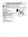
SERVICE
,i,,
,
CAUTION:
&_
,,
AND ADJUSTM
,,,,i,iiii1,,i, iii
, ,
,i ,,11,1111,,111
,,
BEFORE PERFORMING ANY SERVICE OR ADJUSTMENTS:
elease
control
bar. and all moving parts have completely
_
Make
sure
the blade
stopped.
•
Disconnect spark plug wire from spark plug and place where it cannot come in contact with plug.
¸¸¸¸/::2¸i
¸¸ /
LAWN MOWER
TO ADJUST
CUTTING
HEIGHT
See "TO ADJUST CUTTING HEIGHT" in the Operation
section of this manual.
DISCHARGE
GUARD
DRIVE
COVER
The discharge guard, attached to the discharge opening of
your lawn mower, is provided to prevent the possibility of
injury resulting from objects being thrown out of,the discharge opening into the operator mowing position, tf the
discharge guard becomes damaged, it should be replaced.
TO REMOVE/REPLACE
(See Fig. 10)
•
PRESS
DRIVE BELT
•
Remove ddve cover. Remove be t by push ngdownon
gear case pulley.
Turn lawn mower on its side with carburetor and fuel
cap up.
Remove blade.
•
Remove debris shield.
•
Remove belt from engine pulley on crankshaft.
•
Install new belt by reversing above steps.
•
Always use factory approved belt to assure fit and long
life.
.....
_
•
_: : BELT
FIG. 10
12
SERVICE AND ADJUSTMENTS
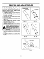
TO ADJUST HANDLE
(See Figs. 11 Thru 13)
SHIPPING POSITION
Your lawn mower handle can be raised or lowered for you r
mowing comfort. Four (4) positions are available: high,
medium high, medium low and low. Handles are shipped
mounted in the medium low position.
°
To change from medium low to medium high position,
the upper and lower handle sections will have to be
turned over (See Fig. 11B).
•
Remove the controls and operator presence control
bar from the upper handle. : .....
•
Remove the starter rope guide from the lower handle.
•
:Remove hairpin cotters.
_Disconnect the lower handle from the handle brackets
(See Fig. 13).
°
Turn the handle over and reassemble the hairpin
cotters that have been removed.
o
Reassemble the starter rope guide.
o
Reassemble the controls and the operator presence
control bar to the upper handle.
MEDIUM LOW
MEDIUM HIGH
FIG. 11B
FIG. 11A
LOW
ill ill
i
•
•
CAUTION: The operator presence control bar must pivot freely to permit blade
: brake engagement when control bar is
released. Do not overtighten the fasteners holding the controls to the upper handle. .....
•
To change from medium low to high position only the
upper handle section will have to be turned over (See
Fig. 12A).
°
To change from medium low to low position, only the
lower handle section will have to be turned over (See
Fig. 12B).
GH
\
FIG. 12B
FIG. 12A
\
LOWER HANDLE
SQUEEZE
TO REMOVE
HAIRPIN COTTER
FIG. 13
13
HANDLE BRACKET
SERVICE AND
ADJUSTMENTS
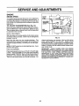
ENGINE
ENGINE SPEED
TOP NO
LOAD
SCREW
Your engine speed has been factory set. Do not attempt to
increase engine speed or it may result in personal injury. If
you believe that engine is running too fast or too slow, take
your mower to an authorized service center for repair and
adjustment.
TO ADJUST
CARBURETOR
IDLE SPEED
ADJUSTING
SCREW
(See Fig. 14)
Minor carburetor adjustments may be required to compensate for differences in fuel, temperature, altitude or load.
The air cleaner and air cleaner cover must be assembled
to carburetor when running.
IDLE
MIXTURE
SCREW
INITIAL ADJUSTMENTWith the engine not running, gently turn idle mixture screw
clockwise until it just closes. Screw may be damaged by
turning it in too far.
Next open the screw one turn counter-clockwise. This
initial adjustment will permit the engine to be started and
warmed up (approximately 5 minutes) pdor to final adjustment,
FIG. 14
mixture) until engine runs unevenly. Now turn idle mixture
screw midway between rich and lean.
Engine should
accelerate smoothly.
If engine does not accelerate properly, the carburetor should be readjusted, usuallyto a richer
mixture, by turning the idle mixture screw counter-clockwise t/8 turn more.
IMPORTANT:
NEVER TAMPER :WITH THE ; ENGINE
GOVERNOR, WHICH IS FACTORY SET FOR PROPER
ENGINE SPEED. OVERSPEEDING
THE ENGINE ABOVE
THE FACTORY
HIGH SPEED
SETTING
CAN
BE
DANGEROUS.
IFYOU THINK THE ENGINE-GOVERNED
HIGH SPEED NEEDS ADJUSTING,
CONTACT
YOUR
NEAREST AUTHORIZED SERVICE CENTER, WHICH HAS
PROPER EQUIPMENTAND
EXPERIENCE TO MAKE ANY
NECESSARY ADJUSTMENTS.
NOTE: DO NOT adjusttop no load adjusting screw, tt was
pre-set at the factory,
FINAL ADJUSTMENTPlace engine speed control lever in "IDLE" or"SLOW" (.il)
position. Adjust idle RPM by turning idle speed adjusting
screw to obtain 1700 RPM. Next, turn idle mixture screw in
(clockwise - lean mixture) until engine just starts to slow.
Then turn idle mixture screw out (counter-clockwise - rich
14
ii
iiiiiii
iiii,
iiiiiiiii
i i
iiiii1,1
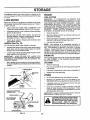
STORAGE
ENGINE
Immediately prepare your lawn mower for storage at the
end of the season or if the unit will not be used for 30 days
or more.
FUEL SYSTEM
When lawn mower is to be stored for a period of time, clean
it thoroughly, remove all dirt, grease, leaves, etc. Store in
a clean, dry area.
•
Clean entire lawn mower (See "CLEANING" in the
Customers Responsibilities section of this manual).
•
Lubricate as shown in the Customers Responsibilities
section of this manual.
IMPORTANT: IT 1S IMPORTANT TO PREVENT GUM
DEPOSITS FROM FORMING IN ESSENTIAL FUEL
SYSTEM PARTS SUCH AS CARBURETOR, FUEL FILTER,
FUEL HOSE, OR TANK DURING STORAGE. ALSO,
EXPERIENCE INDICATES THAT ALCOHOL BLENDED
FUELS (CALLED GASOHOL OR USING ETHANOL OR
METHANOL) CAN ATTRACT MOISTURE WHICH LEADS
TO SEPARATION AND FORMATION OF ACIDS DURING
STORAGE. ACIDIC GAS CAN DAMAGE THE FUEL
SYSTEM OF AN ENGINE WHILE IN STORAGE.
,
Drain the fuel tank.
J
Be sure that all nuts, bolts, screws, and pins are
securely fastened. Inspect moving parts for damage,
breakage and wear. Replace if necessary.
•
•
Touch up all rusted or chipped paint surfaces; sand
lightly before painting,
LAWN MOWER
HANDLE
•
°
(See Fig. 15)
NOTE" Fuel stabilizer is an acceptable alternative in
minimizing the formation of fuel gum deposits during storage. Add stabilizer to gasoline in fuel tank or storage
container. Always follow the mix ratio found on stabilizer
container. Run engine at least 10 minutes after adding "
stabilizer to allow the stabilizer to reach the carburetor. Do
not drain the gas tank and carburetor if using fuel stabilizer.
You can fold your lawn mower handle for storage.
•
Squeeze the bottom ends of the lower handle toward
each other until the lower handle clears the handle
bracket, then move handle forward.
°
Loosen upper handle mounting bolts enough to allow
upper handle to be folded back.
IMPORTANT:
WHEN FOLDING THE HANDLE FOR
STORAGE OR TRANSPORTATION, BE SURE TO FOLD
THE HANDLE AS SHOWNOR YOU MAY DAMAGE THE
CONTROL CABLES.
i
•
Start the engine and let it run until the fue! lines and
carburetor are empty.
Never use engine or carburetor cleaner products in the
fuel tank or permanent damage may occur.
Use fresh fuel next season.
ENGINE OIL
Drain oil (with engine warm) and replace with clean engine
oil. (See "ENGINE" in the Customers Responsibilities
section of this manual).
When setting up your handle from the storage position,
the lower handle will automatically lock into the mowing
position.
CYLINDER
•
•
LOWER HANDLE
l
Remove spark plug.
Pour one ounce (29 ml) of oil through spark plug hole
into cylinder.
Pull starter handle slowly a few times to distribute oil.
Replace with new spark plug.
MOUNTING
PIN
OTHER
SQUEEZE TO FOLD
•
Do not store gasoline from one season to another.
•
Replace your gasoline can if your can starts to rust.
Rust andio r dirt in your gasoline will cause problems.
•
If possible, store your unit indoors and cover it to give
protection from dust and dirt.
°
Cover your unit with a suitable protective cover that
does not retain moisture. Do not use plastic. Plastic
cannot breathe which allows condensation to form and
will cause your unit to rust.
IMPORTANT: NEVER COVER MOWER WHILE ENGINE
AND EXHAUST AREAS ARE STILL WARM.
HAIRPIN
COTI'ER
OPERATOR PRESENCE
CONTROL BAR
UPPER HANDLE_
FOLD FORWARD
_._,
FORSTORAGE
'_.
CAUTION: Never store the lawn mower
ing where fumes may reach an open
with
in the
tank the
inside
a buildflamegasoline
or spark.
:Allow
engine
to
cool before storing in any enclosure.
D BACKWARD
MOWING
ill
i
i
POSITION
]
LOWER HANDLE
FIG. 15
:15
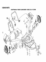
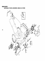
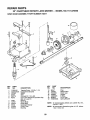
REPAIR PARTS
CRAFTSMAN
22" ROTARY LAWN MOWER - MODEL NO. 917.378590
43
39
16
4O
I
18
42
38
1
36
31
62
51
,43
49
45
45
56
38
52
REPAIR PARTS
CRAFTSMAN
KEY
NO.
,.J.
"4
1
2
3
4
5
7
8
9
10
11
12
13
16
17
18
19
22
23
24
25
26
27
28
29
30
31
32
33
35
36
38
39
40
41
PART
NO.
133088X479
STD541425
130861
128415
103672X
131959
85827
51793
136376
88348
84676X479
74350424
54583
750157
701971X479
701969X479
128797
750097
87584X004
750149
12000014
87590
87593
87589
751592
750388X459
750386X459
74760612
750085X007
84920
850855X004
87877
750913X004
61651
22" ROTARY
DESCRIPTION
Upper Handle
Locknut
Zone Control Cable
Pop Rivet
Rope Guide
Handle Bolt
Cable Clip
Hairpin Cotter
Handle Knob
Flat Washer 3/8
Lower Handle
Hex Head Screw 1/4-20 x 1-1/2
Hex Tapping Screw 1/4-20 x 1/2
Support Rod
Handle Bracket Assembly (Left)
Handle Bracket Assembly (Right)
Rear Deflector
Hex Washer Head Screw #10-24 x 1/2
Deflector Bracket
Discharge Guard
E-Ring
Hinge Rod
Housing Bracket
Torsion Spring
Locknut
Support Bracket (Left)
Support Bracket (Right)
Hex Head Bolt 3/8-16 x 3/4
Wheel Adjusting Bracket
Spacer
Selector Spring
Selector Knob
Axle Arm Assembly
Rear Spring Washer H/W
LAWN MOWER
KEY
NO.
42
43
44
45
46
47
48
49
50
51
52
53
54
55
56
57
59
62
63
64
68
- MODEL
PART
NO.
84921
88017
57143
83923
85463
59289
55187
STD541425
851201X004
134612
850998
851084
850263
851074
850973
851514
700869X479
48324
84596
87677
141131
134027X479
141192
141193
NO. 917.378590
DESCRIPTION
Shoulder Bolt
Wheel & Tire Assembly
Wave Washer
Locknut 3/18-16
Danger Decal
Flat Washer
Thread Cutting Screw 5/16-18 x 3/4
Locknut
Washer
Debris Shield
Hex Head Thread Rolling Screw 3/8-16 x 1-1/8
Hex Head Screw 3/8-24 x 1-3/8 (Grd. 8)
Helical Lock Washer
Hardened Washer
Blade 22"
Blade Adapter
Front Baffle
Lawn Mower Housing (Incl. Ref. #46,59)
Engine Pulley
Hi-Pro Key #HP 505
Engine - Briggs & Stratton - Model No. 128802,
Type No. 0519-21
Rear Baffle (Not Shown)
Owner's Manual (English)
Owner's Manual (Spanish)
Available accessories not included with lawn mower:
7133072
71 33201
7_!33623
71 33500
71 33300
71 33316
Grass Catcher
Mutcher Kit
Gas Can (2.5 gal.)
Fuel Stabilizer
SAE 30W Oil (20 oz.)
Mower Cover
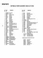
REPAIR PARTS
CRAFTSMAN
22" ROTARY LAWN MOWER - MODEL NO. 917.378590
,%
i
24
29
21
o_
13
26
1
30
REPAIR PARTS
CRAFTSMAN
KEY
NO.
_D
1
2
3
4
5
6
7
8
9
10
12
I3
14
15
21
22
23
24
25
PART
NO.
851509
STD541425
48029
750029
137076
137078
750097
87930
700875
4802
69180
88118
67725
87877
88080
137054
12000058
700953
86960
22" ROTARY LAWN MOWER - MODEL NO, 917,378590
DESCRIPTION
Control Bar
Locknut 1/4-20
Control Head Kit
Screw #10-24 x 2
Control Cable Assembly
V-Belt
Hex Washer Head Screw #10-24 x 1/2
Clip Guide (Housing)
Carriage Bolt 1/4-20 x 2
Washer
Locknut #10-24
Fett Washer
Washer 1/2 x 1-1/2x.134
Selector Knob
Dust Cover
Pinion
E-Ring
Wheel & Tire Assembly
Wheel Bushing
KEY
NO.
26
27
28
29
30
32
34
35
36
37
39
40
41
42
43
44
45
46
PART
NO.
52160
85179
77400
702182
87866
137088
77881
48323
132010
137052
75192
850848
137090
702511
751809
751810
86012
851552
DESCRIPTION
Flat Washer
Retainer Clip
Hubcap
Drive Cover Decal
Pan Head Tapping Screw #10-24 x 2-3/4
Drive Cover
Spacer
Drive Control Cable Kit
Flanged Locknut 3/8-16
Drive Pulley
Spring
Hi-Pro Key
Spring
Gear Case Assembly (Complete)
Wheel Adjuster Assembly (Left)
Wheel Adjuster Assembly (Right)
Drive Shaft Cover
Pan Head Hi Lo Screw #10-16 x .63
REPAIR PARTS
22" CRAFTSMAN
GEAR
CASE
ASSEMBLY
ROTARY LAWN MOWER
PART
NUMBER
- - MODEL
NO. 917,378590
702511
7
17
15
14
I
KEY
NO.
1
2
3
4
5
6
7
8
9
10
11
12
PART
NO.
17490416
137055X004
137053
57072
702710
48373
77881
137051
137074
57079
131484
700343
DESCRIPTION
Tapping Screw 1/4-20x 1-1/4
Engagement Bracket
Shifter
Seal
Grooved Pin 1/8 x 5/8
Gear Case Halves Kit (Includes Key
Noso 4, 5, and 7)
Bearing
Worm Shaft
Drive Shaft
Hardened Washer
Clutch Yoke
Bushing
2O
KEY
NO.
PART
NO.
DESCRIPTION
13
14
15
16
17
18
19
86447
137050
750436X
750369
12000003
850848
81585X004
Plug
Helical Gear
Clutch Jaw
Grease
E-Ring
Hi-Pro Key
Spring Bracket
NOTE:
To reseal housing halves use Locktite No. 515,
Part No. 77923
NOTE:
All component dimensions given in U.S. inches.
1 inch = 25.4 mm
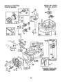
MODEL NO. 128802
TYPE NO. 0519-21
BRIGGS & STRATrON
4-CYCLE ENGINE
96_
968
621
21
MODEL NO. 128802
TYPE NO. 0519-21
BRIGGS & STRATTON
4-CYCLE ENGINE
22
572
3O7
9A
842 <_
8_
306
7
5
8
-k REQUIRES SPECIAL TOOLS
TO INSTALL. SEE REPAIR
INSTRUCTION MANUAL.
307
22
BRIGGS & STRATTON
4-CYCLE ENGINE
MODEL NO. 128802
TYPE NO. 0519-21
9
842_
524 0
104
134
116
Q
634
977 CARBURETOR
617
GASKET
127
617
116
634
SET
121 CARBURETOR
r rl
Ii
KIT
33_3
334
883
851
"_
613
188A
843 @
670A
23
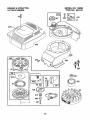
BRIGGS & STRATTON
4-CYCLE ENGINE
MODEL NO. 128802
TYPE NO. 0519-21
os!
19721
_
_/_
670
I
I
949
304
363
f
r
_332
1016
57
455
69
456 (_
515
69A
L
24
MODEL NO. 128802
TYPE NO. 0519-21
BRIGGS & STRATTON
4-CYCLE ENGINE
KEY PART
NO. NO.
1
2
3
5
7
8
9
9A
10
11
12
13
15
16
18
20
22
23
24
25
26
27
28
29
32
33
34
35
40
45
46
493260
293708
299819
214193
272200
495786
272481
272238
94650
231685
272198
94547
94720
493362
94388
493279
399781
94220
94612
492177
222698
493262
493385
493386
493387
493261
493388
493389
493390
26026
298909
298908
49O566
490743
94699
262651
262652
262224
93312
262204
492830
KEY PART
NO. NO.
DESCRIPTION
47
52
54
55
56
57
58
Cylinder Assembly
Bushing, Cylinder
* Seal, Oil
Head, Cylinder
* Gasket, Cytinder Head
Breather Assembly
* Gasket, Valve Cover
* Gasket, Baffle Plate
Screw, Hex Head
Tube, Breather
* Gasket, Crankcase
Screw, Cylinder Head
Plug, Oil Drain
Crankshaft
Timing Gear Key
Sump, Engine
* Seal, Oil
Screw, Hex Head
Screw, Hex Head
(Used in Hole Nearest Breather)
Flywheel
Key, Flywheel
Piston Assembly, Standard Size
Piston Assembly, .010" Oversize
Piston Assembly, .020" Oversize
Piston Assembly, .030" Oversize
Ring Set, Piston, Standard Size
Ring Set, Piston, .010" Oversize
Ring Set, Piston, .020" Oversize
Ring Set, Piston, .030" Oversize
Lock, Piston Pin
Pin, Piston, Standard Size
Pin, Piston, .005" Oversize
Rod, Connecting
Rod, Connecting, .020" Undersize
Screw, Connecting Rod
Valve, Exhaust
Valve, Intake
Spring, Valve
Retainer, Valve Spring
Tappet, Valve
Gear, Cam
493737
272199
94526
492831
493824
262594
280399
59 396892
60 393152
65 94696
69 280973
69A 224322
81 223664
95 94098
98 398185
98A 493280
104 231371
116
--118 493765
121 493762
124 94525
125 496625
127
--130 223470
131 493267
133 398187
134 398188
137
--163 272653
187 492790
188 398540
188A 94644
201 262579
*
**
***
DESCRIPTION
Slinger, Oil
* Gasket, Intake Elbow
Screw, Hex Head
Housing, Rewind Starter
Pulley, Rewind Starter
Spring, Rewind Starter
Rope, Rewind Starter
(Cut To 88-5/8")
Insert, Starter Grip
Grip, Starter Rope
Screw, Hex Head
Washer, Spring
Washer, Flat
Lock, Muffler Screw
Screw, Round Head
Screw, Idle Adjustment
Screw, Speed Adjustment
** Pin, Float Hinge
*** Gasket, Sealing (Sold in Kit Only)
** Valve Kit, Needle
Carburetor Kit
Screw, Carburetor Mounting
Carburetor
** Plug, Welch (Sold in Kit Only)
Valve, Throttle
Shaft, Throttle
Float, Carburetor
Valve, Inlet (Includes Seat)
*** Gasket, Bowl (Sold in Kit Only)
* Gasket, Air Cleaner
Hose, Fuel
Screw, Hex Head
Screw, Hex Head
Link, Governor
Included in Gasket Set (496117)
Included in Carburetor Kit (493762)
Included in both Carburetor Kit (493762),
and Carburetor Gasket Set (490937)
NOTE: All component dimensions given in U.S. inches
1 inch = 25.4 mm
25
MODEL NO. 128802
TYPE NO. 0519-21
BRIGGS & STRA'n'ON
4-CYCLE ENGINE
KEY PART
NO. NO.
209
227
230
258
284
300
304
305
306
307
332
333
334
337
356
358
363
383
387
455
456
459
461
515
523
524
525
529
562
572
592
601
606
608
262660
492349
67072
94512
94511
496106
493293
94786
224324
94515
92284
802574
94731
802592
398808
496117
19069
89838
496115
224250
224321
492833
262626
262625
495264
280393
495265
281299
92613
224328
231082
93807
224815
493295
Includes:
613
615
616
617
620
621
94231
94474
262578
270344
495976
396847
KEY PART
NO. NO.
DESCRIPTION
Spring, Governor
Lever, Governor
Washer, Thrust
Screw, Hex Head
Screw, Hex Head
Muffler, Exhaust
Housing, Blower
Screw, Seres
Shield, Cylinder
Screw, Hex Head
Nut, Flywheel
Armature, Magneto
Screw, Sems
Plug, Spark
Wire, Ground
Gasket Set
Puller, Flywheel
Wrench, Spark Plug
Primer, Carburetor
Cup, Starter
Retainer, Starter
Pawl, Rachet
Pin, Shaft
Spring, Retainer
Cap, Oil Filler
* Seal, Filler Tube
Tube, Oil Fill
Grommet
Bolt, Governor Lever
Baffle, Cylinder
Nut, Hex
Clamp, Hose
Strap, Bracket
Starter, Rewind
94128
Screw, Sems
92987
Nut, Hex
Screw, Hex Head
Fastener
Crank, Governor
*** Seal, Intake Elbow
Bracket, Carburetor
Switch, Stop
625 281025
634
--635 66538
670 280512
670A 493823
741 262598
842 280966
843 272616
847 495263
851 221798
869 213512
870 213513
871 262001
63709
883 272253
922 262640
923 493442
949 496642
955 493637
957 397974
966 496116
967 491588
968 281340
969 94120
971 94121
971A 94749
972 495224
975 493640
977 490937
1016 224278
1019 496658
DESCRIPTION
Tube, Fuel Intake
*** Washer, Shaft (Sold in Kit Only)
Elbow, Spark Plug
Spacer, Fuel Tank
Spacer, Bracket
Gear, Timing
*Seal, O-Ring
Sleeve, Lever
Tube Assembly, Oil
Terminal, Ignition Cable
Seat, Intake Valve
Seat, Exhaust Valve
Guide, Exhaust Vaive
Guide, Intake Valve
Gasket, Muffler
Spring, Brake
Brake Assembly
Guard, Finger
Screw, Fuel Bowl
Cap, Fuel Tank
Base, Air Cleaner
Filter, Air
Cover, Air Cleaner
Screw, Hex Head
Screw, Hex Head
Screw, Hex Head
Tank, Fuel
Bowl, Float
Gasket Set, Carburetor
Cover, Pulley
Label Kit
RPM Settings: Low Speed: 1900-2100
High Speed: 3000-3200
*
**
***
Included in Gasket Set (496117)
Included in Carburetor Kit (493762)
Included in both Carburetor Kit (493762),
and Carburetor Gasket Set (490937)
NOTE: AII component dimensions given in U.S. inches
1 inch = 25.4 mm
26
TROUBLESHOOTING
POINTS
PROBLEM
CAUSE
CORRECTION
Does not start
1.
2.
3.
4.
Dirty air filter.
Out offuel.
Stale fuel.
Water in fuel.
1.
2.
3.
4.
Clean/replace air filter.
Fill fuel tank.
Drain tank and refill with fresh clean fuel_
Drain fuel tank and carburetorand refill tank with fresh
5.
6.
7.
8.
9.
Spark plug w=re is disconnected.
Bad spark plug.
Loose blade or broken blade adapter.
Control bar in released posit_on
Control bar defective
5.
6_
7.
8.
9.
gasoline_
Connect wire to plug.
Replace spark plug.
Tighten blade bolt or replace blade adapter_
Depress control bar to handle.
Replace control bar.
1.
1.
Set in "Higher Cut" position.
2.
3.
4.
5.
6.
Rear of lawn mower housing/blade dragging
in heavy grass.
Cutting too much grass.
Dirty air filter.
Buildup of grass, leaves and trash under mower.
Too much oil in engine.
Walking speed too fast.
2.
3.
4.
5.
6.
Set in "Higher Cut" position.
Clean/replace air filter.
Clean underside of mower housing.
Check oil level.
Cut at slower walking speed.
Poor cut - uneven
1.
2.
3.
4.
Worn, bent or loose blade
Wheel heights uneven.
Low engine speed.
Buildup of grass, leaves, and trash under mower.
1,
2.
3.
4.
Replace blade. Tighten blade bolt,
Set all wheels at same height.
Set engine speed control in fast position.
Clean underside of mower housing.
Excessive
1.
2.
Worn, bent or loose blade.
Bent engine crankshaft.
1.
2.
Replace blade, Tighten blade bolt,
Contact an authorized service center/department_
I.
Engine flywheel brake is on when control bar is
released.
1.
2.
3.
4.
Bent engine crankshaft
Blade adapter broken.
Blade dragging in grass.
2.
3.
4.
Depress control bar to upper handle before
pulling starter rope.
Contact an authorized service center/department.
Replace blade adapter.
Move lawn mower to cut grass or to hard surface
to start engine.
2,
Belt not ddving.
2.
Put belt on pulleys or replace belts if broken.
1.
2.
Cutting height too tow.
Lift on blade worn off.
3.
4.
Catcher not venting air.
Low engine speed.
I.
2,
3.
4,
Raise cutting height.
Replace blade.
Clean grass catcher.
Set eng{ne speed control in fast position.
1.
2.
1.
2.
3.
Grass is too high or wheel he=ght is too low.
Rear of lawn mower housing/blade dragging
in grass.
Grass catcher too full.
4.
Handle height position not right for you.
Raise cutting height.
Raise rear of lawn mower housing one (l)
setting higher.
Empty grass catcher.
Adjust handle height to suit.
Loss of power
vibration
Starter rope hard to pull
(Self-Propelled
Mowing)
Grass catcher not filling
(If so equipped)
Hard to push
3.
4.
I:RRFTZMRN®
OWNER'S
MANUAL
5.5 HORSEPOWER
22" SIDE DISCHARGE
POWER PROPELLED
ROTARY LAWN MOWER
Each lawn mower has its own model number.
gine has its own model number.
MODEL NO.
917.378590
Each en-
The mode! number for your lawn mower witi be found on a
decal attached to the rear of the lawn mower housing.
The model number for your engine wi{l be found on the
blower housing of the engine.
All parts listed herein may be ordered from any Sears,
Roebuck and Co. Service Center/Department and most
Retail Stores.
WHEN ORDERING REPAIR PARTS, ALWAYS GIVE THE
FOLLOWING INFORMATION:
• PRODUCT- LAWN MOWER
• MODEL NUMBER - 9!7.378590
* ENGINE - BRIGGS & STRATTON - MODEL
HOW TO ORDER
REPAIR PARTS
NO. 128802, TYPE NO. 0519-21
• PART NUMBER
• PART DESCRIPTION
consider Sears has service units nationwide staffed with
Sears trained technicians.., professional technicians
specifically trained to _nsure that we meet our pledge to
you, we service what we sell.
141192
08/20/93
Printed in U.S.A.
II
II