1
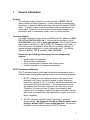
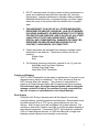
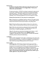
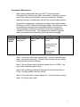
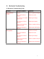
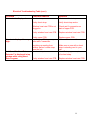
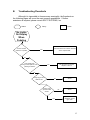
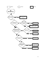
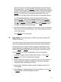
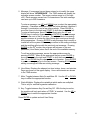
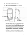
Table of Contents
Section
I.
General Information
II.
Theory of Operations
III.
Mechanical Troubleshooting
IV.
Electrical Troubleshooting
V.
Adjustments and Parts Replacement
VI.
Assembly Drawings and Part List
Page
1
I.
General Information
Purpose
This manual provides information for the servicing of SCIFIT PROII®
series cordless all-body ergometers. It uses systematic troubleshooting
procedures to address problems that may arise with the cordless PROII®
series. The actions taken to resolve problems must be performed in the
order stated. Deviating from this sequence may cause damage to the
equipment, lead to unnecessary repairs, and/ or void the warranty.
Technical Support
For further assistance in the service of SCIFIT products, please call (800)
745-1373 or (918) 359-2000, ext 3. We can also be reached by fax at
(918) 359-2045 or by e-mail at [email protected]. The Product Support
department is staffed from 7 AM to 6 PM CST Monday through Friday. A
voicemail service is available 24 hours daily for recording messages to
request technical support and to order replacement parts. Our mailing
address is 5151 S. 110th E. Avenue, Tulsa, OK 74146.
Please have the following information prior to calling product
support:
• Model number of equipment
• Serial number of equipment
• Point of contact name, address, and phone number
• Detailed description of symptoms encountered
SCIFIT Statement of Warranty
SCIFIT warranties new products against defective workmanship and/ or
materials under normal and proper use subject to the following limitations:
1. SCIFIT’s obligation to the original purchaser shall apply to both
parts and cost of labor required to replace or repair a defective
product for a period of one (1) year from the user purchase date as
documented by the warranty card. If the customer fails to return
the warranty card, the date of shipment from the factory is used.
Thereafter, for a period of two (2) years, such obligation shall
extend only to the supply of replacement parts or products with any
labor costs associated with such replacement or repair to be at the
Buyer’s expense.
2. SCIFIT’s obligation shall be limited to repairing or replacing
defective parts. No allowance shall be granted for repairs made
by Buyer without SCIFIT’s prior written approval. The decision
to replace or repair shall be solely at SCIFIT’s election.
2
3. SCIFIT’s warranty does not apply to parts requiring replacement or
repair due to abnormal wear and tear, improper use, corrosion
(perspiration), improper maintenance, improper rated grounded or
dedicated electrical circuits, or improper storage, nor does it apply
where all or part of the product has been altered from its original
state.
4. THIS WARRANTY IS IN LIEU OF ALL OTHER WARRANTIES,
EXPRESSED OR IMPLIED, ARISING BY LAW OR OTHERWISE
INCLUDING WARRANTY OR MERCHANTABILITY OF FITNESS
FOR PARTICULAR PURPOSE, AND IS IN LIEU OF ALL OTHER
LIABILITIES OF SCIFIT INCLUDING DIRECT, INDIRECT,
SPECIAL AND CONSEQUENTIAL DAMAGES OR PENALTIES
EXPRESSED OR IMPLIED WHETHER ARISING OUT OF
CONTRACT, NEGLIGENCE, OR OTHER TORT.
5. Certain wear items are excluded from warranty coverage unless
determined to be defective. These items include, but are not
limited to:
Rubber Grips
Seat
6. The following items are covered for a period of one (1) year only:
Adjustable and Fixed Crank Systems
Contact Heart Rate Grips
Heart Rate PCB/ Transmitter
Freight and Shipping
SCIFIT is NOT responsible for the repair or replacement of any unit or part
damaged during transit or installation. Fire, flood, and acts of God are
NOT covered under this warranty. The customer is responsible for
pursuing all freight damage claims with the appropriate transit company.
If the customer signs for freight-damaged goods without noting the
damage on the bill of lading, the customer is solely responsible for
the cost of repair or replacement for such freight damage.
Parts Supply
During the first 30 days, warranty parts will be shipped via next day
overnight delivery, excluding international shipments. Determination must
be made before 2:00 p.m. CST on any given weekday for next day
delivery. After 30 days, parts will be shipped via ground shipment. The
customer is welcome to request overnight or second day parts shipping at
the customer’s expense. If requested, SCIFIT will charge the customer’s
UPS or Federal Express account, or COD the difference in freight cost
between ground shipment and overnight or second day.
3
Return Parts
In order to research problems and ensure they do not reoccur, the
rapid return of defective parts is our biggest help! Thank you in
advance for your assistance.
On electronics orders, a $100.00 core charge is assessed to each printed
circuit board. This amount will be credited once the boards have been
received by SCIFIT. All defective parts must be returned to the SCIFIT
factory within 20 days of receipt of replacement part for invoice credit.
Otherwise, SCIFIT will expect payment on the core charge net 30 days.
Please follow these three (3) easy steps for returning parts:
Step 1: Keep the box and packing material in which the new parts arrived.
Locate the enclosed prepaid UPS return label. The return label is only for
the parts that need to be returned as denoted on the picking ticket.
Step 2: Wrap the defective part and place in the box for a safe return.
Include a copy of the picking ticket that came with the replacement part.
Step 3: When the parts have been packaged, place the prepaid UPS
return label on the outside of the box. Drop the package at any UPS
service center or hand the package to any UPS driver.
When all of the parts are received and inspected at the factory, a credit
will be issued for the original parts invoice. Attention service
companies: Warranty labor invoices will NOT be paid until required
defective parts are returned to the factory.
Installation
SCIFIT is NOT responsible for the repair or replacement of any unit or part
damaged during installation. The customer is responsible for inspection of
each unit and part for damage at the time of installation. The customer is
responsible for pursuing all damage claims with the installer.
Service Labor
Where applicable, SCIFIT Product Support will arrange a local field
service technician to provide field support. Every effort will be made to
schedule service during the two (2) working days following notification of a
problem or as soon as repair parts are available to the field service
technician. Where possible, parts will be supplied in advance of the field
service technicians so that the product is repaired with one (1) call. All
jobs to be performed under labor warranty must have SCIFIT’s prior
written approval or they will not be paid.
4
Preventative Maintenance
After training, always wipe down your SCIFIT exercise product.
Perspiration that continuously settles on the frame, upholstery, casings,
and control panels may eventually cause rust or damage. Damage
resulting from lack of maintenance will NOT be covered under warranty.
Preventative maintenance, completed according to the schedule below,
will keep your SCIFIT elliptical functioning properly. We realize your time
is valuable and have kept these maintenance items to a minimum.
This preventative maintenance schedule assumes the equipment is
utilized 6 to 8 hours per day. If the equipment is utilized to a greater
extent, the maintenance schedule must be adjusted accordingly.
Machine
Cordless
PROII®
Weekly
Clean exterior.
See Note 1
Monthly
6 Months
Lube cranks. See Lube chains. See
Note 2.
Note 3.
Yearly
Inspect drive belt
for cracking or
fraying.
Clean interior.
See Note 4.
Note 1: Clean the console with a damp cloth. Use mild soap and warm
water. Dry with a clean towel. The rest of the machine can be cleaned
using common household cleaners.
Note 2: We use Super Lube ® synthetic grease (item no. 82328). Any
high quality industrial grease will do.
Note 3: We use Energy Release ® clear gear and chain lube (item no.
P018). Any high quality chain lube will do.
Note 4: Clean the interior using a damp cloth. Use mild soap and warm
water. Dry with a clean towel.
5
II.
Theory of Operations
The following is a theory of operation that encompasses all the electrical
components, their functions, and how they interact with each other.
Independent electrical components found in SCIFIT’s Cordless product line:
1.
Lower PCB (Power Supply)
2.
Upper PCB (Display)
3.
Generator/Electromagnetic Brake
4.
12 Volt Battery
5.
Wall Pack Receptacle
6.
Hand Grip Heart rate PCB (HG HR)
7.
Wireless Heart rate PCB (Polar)
Component Functions
1. Lower PCB (Power Supply)
A.
Converts the12 to 400 volts AC from the generator into 12 volts DC
using switching power supply technology.
B.
Provides 12 volts DC to upper PCB.
C.
Accepts 12 volts DC from either the battery or wall pack
transformer if unavailable from the generator
D.
Receives Pulse Width Modulation (PWM) signal from the upper
PCB for brake control.
E.
Contains Hi-power MOSFET circuitry that controls the brake.
2. Upper PCB (Display)
A.
Accepts commands from a user.
B.
Displays information to the user.
C.
Regulates 12 volts DC from lower PCB down to 8 volts DC and 5
volts DC.
D.
Operates the 8 and 5 volt DC serial communications (c-safe and
cardio-key)
E.
Provides 5 Volts DC to the contact and wireless heart rate jacks.
F.
Receives signals from the contact and wireless heart rate PCB’s.
G.
Contains 5 volt DC display (LED) drivers.
H.
Contains the 5 volt DC memory and processor components.
I.
Provides PWM signal to lower PCB for brake control.
3. Generator/Electromagnetic Brake
Generator:
o A three (3) phase generator that produces 0 to 400 volts AC
depending on the RPM’s.
o Provides AC voltage to the lower PCB.
6
Electromagnetic Brake
o An eddie current transformer that uses rising and collapsing
electromagnetic fields to slow down the generator magnet traveling
through it’s field.
o Controlled by the lower PCB.
4. 12 Volt DC Battery
A. 12 volt sealed lead acid 1.3 Amp Hour Battery.
B. Provides 12 Volts DC to lower PCB during:
o Pause mode
o Between intervals
o Provides power for 15 seconds after generator stops.
5. Wall Pack Receptacle
A. 12 volt DC input receptacle that accepts voltage from a DC wall pack.
B. Provides 12 volts DC to lower PCB when a wall pack is connected to it.
C. Aids in battery charging.
6. Hand Grip (Contact) Heart Rate (HG HR) PCB
A. Outputs a square wave to the upper PCB.
B. Equipped with right and left grip inputs.
C. Power and ground is provided by the upper PCB.
7. Wireless Heart rate PCB
A. Outputs a square wave to the upper PCB.
B. Has a 30” range and position is critical.
C. Power and ground is provided by the upper PCB.
System Functions
Starting the Machine
A.
Pedaling the machine rotates the generator, which generates a
current to power the electronics. A minimum of 13 RPM or 10 FPM
must be maintained to keep machine powered up.
B.
The generator provides AC voltage to the lower PCB. The lower
PCB then provides DC voltage to the upper PCB.
C.
The User controls the resistance by selecting a level on the display.
The display sends a PWM signal which varies, depending on the
level selected. The signal travels through the ribbon cable to the
lower PCB. The lower PCB sends a square wave signal to the
transformer on the brake which is proportionate to the amount of
resistance commanded.
D.
The brake LED on the lower PCB, labeled D38 on older units and
D19 on newer units, will illuminate any time braking is applied. The
intensity of the LED is proportional to the level of resistance.
7
E.
The battery is charged anytime there is more than 13 RPM’s
present.
Stopping the unit
A.
When pedaling is discontinued, the brake continues to spin.
B.
The battery will engage once the actual RPM’s dip below 13.
C.
The battery remains active for 15 seconds and then a transistor that
connects the battery to the rest of the lower PCB is unlatched. The
transistor will remain unlatched until the unit sees an rpm value
above 13 rpm’s.
Using the Wall Pack
A.
Using the wall pack will allow the machine to be powered up
without pedaling. Quick Start or any other program can be selected
without have to pedal first. The machine will be powered up
constantly when the wall pack is in use.
8
III.
Mechanical Troubleshooting
A. Mechanical Troubleshooting Table
Problem
Possible Reasons
Solutions
Hand cranks wobble
when cranks are
rotated.
Handle shaft is loose or
stripped.
Tighten or replace handle
shaft, if threads are damaged.
Arm crank threads are
stripped.
Replace arm crank.
Igus bearings in the handle
are worn out.
Replace Igus bearings.
Igus bearings in hub are
worn out.
Replace Igus bearings.
Cotter pins through inner
hubs are not tight.
Tighten or replace cotter pins.
Upper axle bearings are
worn out.
Pedal is loose or stripped.
Replace upper axle bearings.
Foot cranks wobble
when pedaled.
Tighten or replace pedal, if
threads are damaged.
Foot crank threads are
stripped.
Replace foot crank.
Igus bearings in hub are
worn out.
Replace Igus bearings.
Cotter pins through inner
hubs not tight.
Tighten or replace cotter pins.
Lower axle bearings are
worn out.
Replace lower axle bearings.
9
Mechanical Troubleshooting Table (cont.)
Problem
Possible Reasons
Solutions
Hand crank or foot
crank assembly has
side-to-side play.
Cotter pin through the inner
hub is not tight enough.
Tighten or replace cotter pin.
Snap ring is not in snap ring
groove on axle.
Chain is too loose or out of
alignment.
Install snap ring back into
snap ring groove.
Tension or align the chains.
Brake bearings are bad.
Replace brake assembly.
Brake drive pulley bearings
are bad.
Replace bearings or brake
drive pulley assembly.
Upper axle bearings are
bad.
Belt is rubbing against the
brake.
Replace upper axle bearings.
Brake bearings are bad.
Replace brake assembly
Bearings in brake drive
pulley assembly are bad.
Igus bearings in the idler
are worn out.
Replace bearings or brake
drive pulley assembly.
Replace Igus bearings in the
idler or idler assembly.
Upper axle bearings are
bad.
Replace upper axle bearings.
Lower axle bearings are
bad.
Belt is out of alignment.
Replace lower axle bearings.
Belt is over-tensioned.
Re-tension belt.
Brake bearings are bad.
Replace brake.
Brake drive pulley assembly
bearings are bad.
Replace bearings or brake
drive hub assembly.
Cranks lock up while
operating.
Grinding, rubbing, or
scraping noise while
rotating cranks.
Internal squealing noise
occurs when cranks are
rotated but not when
freewheeling.
Internal squealing noise
occurs when cranks are
rotated, as well as when
unit is freewheeling.
Realign belt.
Realign belt.
10
Mechanical Troubleshooting Table (cont.)
Problem
Possible Reasons
Clunking noise from
inside the unit when
cranks are being
rotated.
User is over-speeding brake Increase the work load or
and brake drive pulley
decrease rpms.
because work load too low.
Unit slips when cranks
are rotated.
Clunking noise heard or
felt in one handle or
foot when at the top or
just past the top of the
rotation.
Crunching noise is
heard when cranks are
rotated.
Solutions
Brake pulley is loose.
Fix pulley or replace brake
assembly.
Brake drive pulley bearings
are bad.
Belt is too loose.
Replace bearings or brake
drive pulley assembly.
Tension belt.
Lower PCB is bad.
Popper pin not seating
properly.
Replace lower PCB.
Fix or replace popper pin.
Cotter pin through inner hub Tighten or replace cotter pin.
is not tight enough.
Chains are out of alignment. Realign chains.
Brake bearings are bad.
Replace brake assembly
Bearings in brake drive
pulley assembly are bad.
Replace bearings or brake
drive pulley assembly.
11
IV.
Electrical Troubleshooting
A.
Electrical Troubleshooting Table
Problem
Possible Reason
Solution
No lights are showing on the
upper PCB at idle.
Unit is not in use.
Start rotating cranks (at least
13 RPMs). Unit stays lit for 15
seconds after use unless a wall
pack is in use.
See flowchart.
No lights on upper PCB when Faulty lower PCB.
unit is pedaled.
Faulty upper PCB.
See flowchart.
Bad Telco or ribbon cable
connection.
See flowchart.
Brake is shorted to the frame.
Faulty lower PCB.
Faulty upper PCB.
See flowchart.
Replace lower PCB.
Replace upper PCB.
Bad Telco or ribbon cable
connection.
Fix connection or replace
cable.
Faulty lower PCB.
Replace lower PCB.
Faulty upper PCB.
Battery is weak.
Replace upper PCB.
Charge battery with wall pack.
If problem continues, replace
battery.
Fix connection.
“PAUSED” is displayed in
top display window.
Bad brake to lower PCB
connection.
The PAUSE/CLEAR button has
been pressed during program.
Display resets after starting
program.
Bad Telco or ribbon cable
connection.
Lights on upper PCB are dim.
Lights on upper PCB are
frozen.
Lights on upper PCB flicker
and then go dead.
Lights on upper PCB go out
as soon as you stop pedaling
or go to change direction.
Press START to resume
program or PAUSE/CLEAR to
return to start up screen.
Fix connection or replace
cable.
13 RPMs not maintained.
Maintain 13+ RPMs to keep the
upper PCB lit.
Faulty upper PCB.
Replace upper PCB.
12
Electrical Troubleshooting Table (cont.)
Problem
Possible Reason
Solution
Upper PCB won’t light up
without use of wall pack.
Bad brake to lower PCB
connection.
Fix connection.
Faulty lower PCB.
Replace lower PCB.
Brake shorted to monocoque.
Faulty upper PCB.
Fix short or replace brake.
Replace upper PCB.
Overlay and buttons on upper
PCB not making contact.
Upper PCB is lit up but
values don’t change.
Machine shuts down in
programs but works in
manual mode.
Can’t select program or enter
information and there is no
beep when buttons are
pressed.
Faulty upper PCB.
Secure overlay to upper PCB
by tightening standoffs or
Philips screws.
Replace upper PCB.
Faulty upper PCB.
Replace upper PCB.
Overlay and buttons on upper
PCB not making contact.
Constant resistance.
Intermittent resistance or
spiking.
Faulty lower PCB.
Bad brake to lower PCB
connection.
Secure overlay to upper PCB
by tightening standoffs or
Philips screws.
Replace lower PCB.
Fix connection.
Resistance is different than
when you received unit.
No resistance.
Faulty lower PCB.
Replace lower PCB.
Faulty upper PCB.
Defined unit type has been
changed.
Replace upper PCB.
Redefine unit type. Call SCIFIT
for procedure.
Faulty lower PCB.
Bad brake to lower PCB
connection.
Replace lower PCB.
See flowchart.
Faulty lower PCB.
See flowchart.
Faulty upper PCB.
See flowchart.
13
Electrical Troubleshooting Table (cont.)
Problem
Possible Reason
Solution
No heart rate displayed.
No chest strap worn.
Must wear chest strap.
Faulty chest strap.
Verify chest strap works.
Wireless heart rate PCB is not
plugged in.
Check and fix connection on
back of upper PCB.
Faulty wireless heart rate PCB.
Replace wireless heart rate PCB.
Faulty upper PCB.
Is picking up FM frequency
from radio / transmitter.
Replace upper PCB.
Move radio or transmitter.
Is picking up reading from
another person’s chest strap
near the unit.
No chest strap is worn.
Make sure no one with a chest
strap is standing next to your
unit.
Heart Rate program requires use
of a chest strap.
Faulty wireless heart rate PCB.
Replace wireless heart rate PCB.
Heart rate displayed is very
high.
“---” then “No Heart Rate
Detected” is displayed in top
window while using Heart
Rate Program.
14
B.
Troubleshooting Flowcharts
Although it is impossible to foresee every eventuality, the flowcharts on
the following pages will cover the most common possibilities. If further
assistance is required, please consult SCIFIT SYSTEMS, Inc.
Query
Status
Action
No Lights
On Display
When
Pedaling
Is there constant
resistance on pedals?
Brake is shorted to the chassis. Eliminate
short or replace brake.
Yes
No
Does display beep
during a button press or when
pedaling is initiated?
Six (6) pin telco is insecure:
Replace or Secure.
Yes
No
Is eight (8) pin telco
cable secure?
No
Secure
Yes
Is three (3) pin
generator cable
secure?
No
Yes
Secure
Replace lower PCB. If
ineffective, replace
upper PCB.
15
Query
Status
Action
No
Resistance
Lights on display
while exercising?
Refer To "No Lights On
Display when Pedaling"
Flowchart
No
Yes
When in a
program, does display
report RPM's?
Is three (3) pin
cable connection
from JP1 to brake
secure?
No
No
Clear EEPROM. If Ineffective,
replace lower PCB.
Yes
Yes
Does Brake LED on
lower PCB (D38 or D19)
Illuminate when brake
command is given?
No
Secure
Is six (6) pin telco
cable secure?
Yes
No
Secure
Replace upper PCB.
Yes
Is two (2) pin brake
cable secure?
No
Secure
Yes
Is resistance
across two (2) pin
brake header 9 -11
Ohms ?
No
Yes
Replace brake.
0 Ohms = Short,
< 1000 Ohms = Open
Replace lower PCB.
16
C.
User Setup (Use this procedure for PROII’s thru serial number 650005503.)
User Setup provides club owners and managers with certain information
about their equipment and enables them to customize certain features.
Provide power to the console by either plugging the wall pack into the
machine and outlet or working out at a low level on the machine. Press
and hold SCAN and ENTER for three (3) seconds to enter User Setup.
Press ENTER to move from one parameter to the next parameter.
1. Language: Toggles between English and German. Use the UP or
DOWN keys to select the appropriate language.
2. Model: Displays the model of the machine that is set in the console. If
the wrong model of machine is defined, the unit will not calculate
resistance, watts, and distance correctly.
a. Version High: Displays the upper console’s software version in the
Time window.
4. Version Low: Displays the lower PCB firmware version in the Time
window. If this version number is zero, no communication has been
established between the upper and lower boards.
5. Unit of Measure: Toggles between metric and U.S. units of measure.
Use the UP or DOWN keys to select the appropriate unit of measure.
6. Communications Mode: Toggles between Cardio Key and Csafe
Comm. Use the UP or DOWN keys to select the appropriate
communications mode.
7. Message: If a message has not been entered or is invalid, the upper
display will show “NO MESSAGE”. The TIME window will display the
message screen number. The screen number range is ct1 through
ct25. Each message screen has 10 characters so the total message
can have up to 250 characters.
To enter a message, use UP and DOWN to select the appropriate
character. Characters available include the entire alphabet, numbers 0
through 9, punctuation, and a few other symbols. Press PAUSE to
move the cursor to the right and START to shift the cursor to the left.
To enter a blank space, press PAUSE without using the UP and
DOWN keys to select a character. Press ENTER to save a message
and go to the next of the 25 screens. The only method of accessing
17
previous screens is to enter the User Setup again and move through
all the parameters. Pressing ENTER for any message that is empty or
invalid will tell the system that message number is the ending message
and the scrolling will stop with the previously set message. Pressing
ENTER on the 25th screen, the program will advance to the next
parameter (Hour Meter) since that is the end of the available memory.
To edit an existing message, access the appropriate screen by
pressing ENTER. When at the appropriate screen, press PAUSE to
move the cursor to the right and START to shift the cursor to the left.
Use UP and DOWN to change the character. Press ENTER to save a
message and go to the next screen. Pressing SCAN while editing a
message will clear an existing message.
8. Hour Meter: Displays the elapsed run time in days, hours, and minutes.
Days are shown on the upper display. Hours and minutes are shown
in the TIME window.
Press ENTER to exit User Setup.
D.
User Setup (Use this procedure for PROII’s with serial numbers 650005504 and above.)
User Setup provides club owners and managers with certain information
about their equipment and enables them to customize certain features.
Provide power to the console by either plugging the wall pack into the
machine and outlet or working out at a low level on the machine. Press
and hold SCAN and ENTER for three (3) seconds to enter User Setup.
Press ENTER to move from one parameter to the next parameter.
1. Language: Toggles between English and German. Use the UP or
DOWN keys to select the appropriate language.
2. Model: Displays the model of the machine that is set in the console. If
the wrong model of machine is defined, the unit will not calculate
resistance, watts, and distance correctly.
3. Version High: Displays the upper console’s software version in the
Time window.
4. Unit of Measure: Toggles between US Units and Metric. Use the UP
or DOWN keys to select appropriate measure.
18
5. Message: If a message has not been entered or is invalid, the upper
display will show “NO MESSAGE”. The TIME window will display the
message screen number. The screen number range is ct1 through
ct25. Each message screen has 10 characters so the total message
can have up to 250 characters.
To enter a message, use UP and DOWN keys to select the appropriate
character. Characters available include the entire alphabet, numbers 0
through 9, punctuation, and a few other symbols. Press PAUSE to
move the cursor to the right and START to shift the cursor to the left.
To enter a blank space, press PAUSE without using the UP and
DOWN keys to select a character. Press ENTER to save a message
and go to the next of the 25 screens. The only method of accessing
previous screens is to enter the User Setup again and move through
all the parameters. Pressing ENTER for any message that is empty or
invalid will tell the system that message number is the ending message
and the scrolling will stop with the previously set message. Pressing
ENTER on the 25th screen, the program will advance to the next
parameter (Hour Meter) since that is the end of the available memory.
To edit an existing message, access the appropriate screen by
pressing ENTER. When at the appropriate screen, press PAUSE to
move the cursor to the right and START to shift the cursor to the left.
Use UP and DOWN keys to change the next character. Press ENTER
to save a message and go to the next screen. Pressing SCAN while
editing a message will clear an existing message.
6. Hour Meter: Displays the elapsed run time in days, hours, and minutes.
Days are shown on the upper display. Hours and minutes are shown
in the TIME window.
7. Mets: Toggles between Mets On and Mets Off. Use the UP or DOWN
keys to select the appropriate function.
8. Watts Multiplier: Displays the variable at which watts are multiplied.
This is only for certified ergometer calibration.
9. Key: Toggles between Key On and Key Off. With the key turned on,
the machine will only work when a FITKEY is inserted. Use the UP or
DOWN keys to select the appropriate function.
Press ENTER to update and exit User Setup.
19
V.
Adjustments and Parts Replacement
A.
Upper (Display) PCB Replacement (Use this procedure for
PROII’s thru 650-005503.)
1. Using a Philips screwdriver, remove the four (4) display mounting screws
on the back of the display mounting plate.
2. Disconnect all cables running to the upper PCB (P1558) and remove the
upper console assembly from the unit. Make sure the cables do not fall
into the neck of the unit.
3. Remove the two (2) outer countersunk screws in the back of the plastic
console (A1537), using a Philips screwdriver. This will free the upper PCB
and overlay (P1560) from the plastic console. Do not touch any
components on the PCB. Touching components could cause static
damage. If the wireless heart rate receiver is still plugged into the upper
PCB, unplug it now.
4. Remove the six (6) standoffs from the upper PCB. This may require the
use of a 5/16” nut driver or socket. The upper PCB will separate from the
overlay.
20
5. Install the new upper PCB and replace standoffs. If your unit had two (2)
plastic standoffs, these need to be placed back at the bottom of the new
upper PCB.
6. Plug the wireless heart rate receiver back into the upper PCB. It plugs
into the centermost, 3-pin Molex header.
7. Reinsert the upper PCB assembly into the front of the console.
8. Reinstall the two (2) outer countersunk screws in the back of the plastic
console.
9. Reconnect all cables to the upper PCB.
• When looking at the back of the upper PCB, the Telco cables plug
in along the left edge. The 6-pin plugs into the top plug and the 8pin plugs into the bottom plug.
• If your unit has Cardio Key, the cable plugs into the serial port,
which is the 4-pin Molex header lower right corner.
• If your unit has Broadcast Vision, Cardio Theater, etc., the cable
connects to the 8-pin header located at the bottom center of the
upper PCB.
10. Place the display assembly back onto the mounting plate and install the
four display mounting screws.
11. The model of machine must be defined. (You must rotate the cranks to
power up the upper display to perform this next procedure.) When the
display lights up, see if “ELLIPTICAL” appears in the top window. If so,
press the UP arrow one time to display “PRO”. Once “PRO” is displayed,
press ENTER to save. If no unit type appears in the top window upon
power up, the display has probably been preset at the factory. To verify
this, hold the SCAN, SELECT, and PAUSE for three seconds until a type
of machine appears, then release. Do not continue to hold keys once
the type of unit appears. If “PRO” appears in the top window, press
ENTER to save and exit, unless the unit is equipped with Cardio Key. If
“PRO” doesn’t appear in the top window, press and hold SELECT and the
UP or DOWN arrow until “PRO” does appears. For units with Cardio Key,
when “PRO” appears, press ENTER sixteen times until the top window
shows either “C-SAFE COMM” or “CARDIO KEY”. If “CARDIO KEY” is
displayed, press ENTER three times to exit the mode. If this screen
shows “C-SAFE COMM”, press the UP or DOWN arrow to display
“CARDIO KEY” in the top window, then press ENTER three times to exit
the mode.
21
B.
Upper (Display) PCB Replacement (Use this procedure for
PROII’s with serial numbers 650-005504 thru 650-005636.)
1. Using a Philips screwdriver, remove the four (4) display mounting screws
on the back of the display mounting plate.
2. Disconnect all cables running to the upper PCB and remove the upper
console assembly from the unit. Make sure the cables do not fall into
the neck of the unit.
3. Remove the two (2), outer countersunk screws in the back of the plastic
console, using a Philips screwdriver. This will free the upper PCB and
overlay from the plastic console. Do not touch any components on the
upper PCB. Touching components could cause static damage. If the
wireless heart rate PCB is still plugged into the upper PCB, unplug it.
4. Remove the six (6) standoffs from the upper PCB. This may require the
use of a 5/16” nut driver or socket. The upper PCB will separate from the
overlay.
5. Install the new upper PCB and replace standoffs.
6. Reconnect all cables to the upper PCB.
22
•
Plug the wireless heart rate PCB back into the upper PCB. It plugs
into the bottom 3-pin header on the right side of the upper PCB (as
shown above).
• The ribbon cable plugs into the bottom ribbon cable header on the
right side of the upper PCB.
• If your unit has Broadcast Vision, Cardio Theater, etc., the cable
connects to the 8-pin, +8VDC power header. When looking at the
upper PCB from the front, this header is located on the lower right
backside corner of the upper PCB (as shown above).
7. Reinsert the upper PCB assembly into the front of the console.
8. Reinstall the two (2), outer countersunk screws in the back of the plastic
console.
9. Place the console assembly back onto the mounting plate and install the
four (4) display mounting screws.
10. The model of machine must be defined. (You must rotate the cranks to
power up the upper display to perform this next procedure.) When the
display lights up, see if “UNDEFINED” appears in the top window. If
“UNDEFINED” appears, press the UP arrow one time to display “PRO” or
“PRO 2”. Once “PRO” or “PRO 2” is displayed, press ENTER to save. If
no unit type appears in the top window upon power up, the display has
probably been preset at the factory. To verify this, hold the SCAN,
SELECT, and PAUSE for three seconds until “FACTORY SETTINGS”
appears, then release. Do not continue to hold keys once this
appears. Press ENTER once. If “PRO” or “PRO 2” appears in the top
window, press ENTER eight (8) times until “UPDATING” appears. If
“PRO” or “PRO 2” doesn’t appear in the top window, press and hold
SELECT and the UP or DOWN arrow simultaneously until “PRO” or “PRO
2” does appears.
11. Verify operations of the unit by using different programs.
23
C.
Upper (Display) PCB Replacement (Use this procedure for
PROII’s with serial numbers 650-005637 and above.)
24
1. Remove the five (5) console screws in the console back (P2304), using a
Philips screwdriver.
2. Disconnect all cables running to the display PCB (P2160) and remove
console face (P2303) from the unit. Make sure the cables do not fall
into the neck of the unit.
3. Remove the six (6) screws holding the display PCB to the console face.
This will free the display PCB and overlay from the plastic console. Do
not touch any components on the PCB. Touching components could
cause static damage.
4. Install the new display PCB.
5. Reinsert the six (6) screws through the display PCB and into the console
face. Tighten.
6. Reconnect all cables to the display PCB.
• Plug the wireless heart rate PCB back into the display PCB. It
plugs into the bottom 3-pin header on the right side of the display
PCB (as shown in the drawing).
• The contact heart rate PCB has a cable coming up from the neck of
the unit. This plugs into the top, 3-pin header on the right side of
the display PCB, above the wireless heart rate header (as shown in
the drawing).
• The ribbon cable plugs into the bottom ribbon cable header on the
right side of the display PCB (as shown in the drawing).
• The FITKEY ribbon cable (P2418) plugs into the FITKEY ribbon
cable header on the display PCB. This header is located just
above the contact heart rate header (as shown in the drawing).
• There are two (2) gray Telco cables. The cable from the 8VDC jack
affixed to the console back connects to the 8-pin, +8VDC power
header on the display PCB. The other cable from the COMM jack
affixed to the console back connects to the 8-pin, C-Safe header.
7. Verify connections.
8. Match the console and face up to each other and install the console
screws, using a Philips screwdriver.
9. The model of machine must be defined. (You must rotate the cranks to
power up the upper display to perform this next procedure.) When the
display lights up, see if “UNDEFINED” appears in the top window. If
“UNDEFINED” appears, press the UP arrow one time to display “PRO” or
“PRO 2”. Once “PRO” or “PRO 2” is displayed, press ENTER to save. If
no unit type appears in the top window upon power up, the display has
probably been preset at the factory. To verify this, hold the SCAN,
SELECT, and PAUSE for three seconds until “FACTORY SETTINGS”
appears, then release. Do not continue to hold keys once this
appears. Press ENTER once. If “PRO” or “PRO 2” appears in the top
window, press ENTER eight (8) times until “UPDATING” appears. If
“PRO” or “PRO 2” doesn’t appear in the top window, press and hold
SELECT and the UP or DOWN arrow simultaneously until “PRO” or “PRO
2” does appears.
25
10. Verify operations of the unit by using different programs.
D.
Lower PCB Replacement (Use this procedure for PROII’s with serial
numbers thru 650-005503.)
1. Remove crank retaining bolts and washers, using a 5/32” Allen wrench.
2. On the lower right side crank hub assembly (A1871), pull the black knob
on the popper pin assembly (A1754) out and slide the crank assembly
(A1868) out.
3. On the upper right side crank hub assembly (A1884), pull the black knob
on the popper pin assembly and slide the crank assembly (A1870) out.
4. Remove the popper pin assembly by turning it counterclockwise with a
crescent wrench.
5. Remove the six (6) cover screws and washers holding the right side cover
in place, using a Philips screwdriver.
26
6. Locate the lower PCB (P1559).
7. Disconnect all cables to the lower PCB. Make sure you are grounded
when handling electronics. Do not touch any components on the
lower PCB. Static damage can occur.
8. Remove the four (4) screws mounting the lower PCB, using a Philips
screwdriver.
9. Remove the lower PCB from the unit.
10. Install the new lower PCB in the exact same orientation as the old one.
11. Reconnect all cables to the new lower PCB. Confirm all connections to
the lower PCB match those shown above.
12. Rotate the left upper crank arm to see if the upper display lights up.
13. If the upper display lights up, reinstall the right side cover. If the display
doesn’t light up, verify your connections again.
14. Reinstall the popper pins on both the upper and lower crank hubs. Use a
dab of blue loc-tite on the threads when installing. Do not torque these
down very tight. Over-tightening will cause damage to the threads of
the popper pin or crank hub assembly.
15. Verify the popper pin is functioning properly. Pull the black knob out and
then release. The black knob should return to its lowest position. If it
doesn’t, the popper pin is tightened down too far.
16. Once verified, reinsert the crank assemblies into their respective locations.
17. It is optional whether to reinstall the crank retaining bolts with washers.
18. Rotate cranks to light the upper display. If display lights up, do an
operations test. Use different programs to verify unit is working correctly.
27
E.
Lower PCB Replacement (Use this procedure for PROII’s with serial
numbers 650-005504 and above.)
1. Remove crank retaining bolts and washers, using a 5/32” Allen wrench.
2. On the lower right side crank hub assembly (A1871), pull the black knob
on the popper pin assembly (A1754) out and slide the crank assembly
(A1868) out.
3. On the upper right side crank hub assembly (A1884), pull the black knob
on the popper pin assembly and slide the crank assembly (A1870) out.
4. Remove the popper pin assembly by turning it counterclockwise with a
crescent wrench.
28
5. Remove the six (6) cover screws and washers holding the right side cover
in place, using a Philips screwdriver.
6. Locate the lower PCB (P2161).
7. Disconnect all cables to the lower PCB. Make sure you are grounded
when handling electronics. Do not touch any components on the
lower PCB. Static damage can occur.
8. Remove the four (4) screws mounting the lower PCB, using a Philips
screwdriver.
9. Remove the lower PCB from the unit.
10. Install the new lower PCB in the exact same orientation as the old one.
11. Reconnect all cables to the new lower PCB. Confirm all connections to
the lower PCB match those shown above.
12. Rotate the left upper crank arm to see if the upper display lights up.
13. If the upper display lights up, reinstall the right side cover. If the display
doesn’t light up, verify your connections again.
14. Reinstall the popper pins on both the upper and lower crank hubs. Use a
dab of blue loc-tite on the threads when installing. Do not torque these
down very tight. Over-tightening will cause damage to the threads of
the popper pin or crank hub assembly.
15. Verify the popper pin is functioning properly. Pull the black knob out and
then release. The black knob should return to its lowest position. If it
doesn’t, the popper pin is tightened down too far.
16. Once verified, reinsert the crank assemblies into their respective locations.
17. It is optional whether to reinstall the crank retaining bolts with washers.
18. Rotate the cranks to see if the upper display still lights up. If display lights
up, do an operations test. Use different programs to verify unit is working
correctly.
29
F.
Battery Replacement
1. Remove crank retaining bolts and washers, using a 5/32” Allen wrench.
2. On the lower right side crank hub assembly (A1871), pull the black knob
on the popper pin assembly (A1754) out and slide the crank assembly
(A1868) out.
3. On the upper right side crank hub assembly (A1884), pull the black knob
on the popper pin assembly and slide the crank assembly (A1870) out.
4. Remove the popper pin assembly by turning it counterclockwise with a
crescent wrench.
5. Remove the six (6) cover screws and washers holding the right side cover
in place, using a Philips screwdriver.
30
6. Locate the battery.
7. Disconnect the two (2) wires connected to the battery. The red wire is
connected to the positive terminal while the black wire is connected to the
negative terminal.
8. Remove the three (3) Philips screws through the battery mounting bracket
(A1570).
9. Remove the old battery.
10. Install the new battery.
11. Insert the three (3) Philips screws through the battery mounting bracket
and tighten.
12. Connect the two (2) wires to the battery. The red wire is connected to the
positive terminal while the black wire is connected to the negative
terminal.
13. Verify connections.
14. Test operation of the unit.
15. If everything works fine, re-install the right side cover and crank
assemblies.
31
G.
Wireless HR Replacement (Use this procedure for PROII’s with
serial numbers through 650-005XXX.)
H.
Wireless HR Replacement (Use this procedure for PROII’s with
serial numbers 650-005XXX thru 650-005XXX.)
I.
Wireless HR Replacement (Use this procedure for PROII’s with
serial numbers 650-005XXX and above.)
J.
Brake Replacement
(Right Side View)
32
(Left Side View)
1. Remove the crank arms and both side covers, using the Crank Arm and
Cover Removal procedure.
2. Remove the two (2) nuts holding the tensioning bolt to the tensioning
bracket.
3. Remove tensioning bolt from the frame.
4. Cut the tie wrap mounting the 2-pin brake cable to the frame.
5. Disconnect the 2-pin brake cable affixed to the brake transformer from the
extension cable leading to the lower PCB.
6. Unplug the 3-pin brake cable from the backside of the brake assembly
(S1908) and hook the cable from the cable hook tab.
7. Loosen each brake mounting bolt 3-4 turns.
8. Unhook the poly-v belt (P1955) from around the brake pulley.
9. Remove the two (2) brake mounting bolts on the right side of the frame.
Let the brake flange rest on the L-shaped tab welded to the frame.
10. Remove the brake spacer (A2202) on the right side.
11. Support the brake and remove the two (2) brake mounting bolts on the left
side of the frame.
12. While supporting the brake, remove the brake spacer on the left side.
13. Remove the brake assembly from the unit. Be very careful, as the brake
assembly weighs approximately 32lbs.
14. Rest the new brake assembly on the L-shaped tab welded to the frame on
the right side.
15. Place the brake spacer in place on the right side and start the two (2)
brake mounting bolts. Each brake mounting bolt should have a flat
washer followed by a lock washer. Tighten bolts finger tight
33
16. While still supporting the brake assembly, insert the brake spacer on the
left side and start the two (2) brake mounting bolts. Each brake mounting
bolt should have a flat washer followed by a lock washer. Tighten bolts
finger tight.
17. Reinstall the poly-v belt on the brake pulley.
18. Insert the tensioning bolt back through the frame and tensioning bracket.
19. Start one (1) of the two (2) nuts on the tensioning bolt.
20. Align the poly-v belt.
21. Turn the nut on the tensioning bolt resting against the tensioning bracket
clockwise until the belt is taut.
22. Tighten all four (4) brake mounting bolts.
23. Install the second nut on the tensioning bolt and tighten.
24. Make sure the poly-v belt is running straight by spinning the brake
assembly.
25. Reconnect the 2-pin brake cable affixed to the brake transformer to the
extension cable from the lower PCB.
26. Reconnect the 3-pin cable to the backside of the brake assembly.
27. Tie-wrap cables to the frame just below the brake transformer.
28. Verify all connections and bolt tightness.
29. Reinstall the covers and crank arms.
30. Test operations of the unit. Make sure the poly-v belt does not slip at high
resistance. If it does, the poly-v belt is not tight enough.
K.
Idler Replacement
L.
Shimano Removal / Replacement
M.
Brake Drive Hub Assembly Replacement
34
N.
Adjustable Crank Locking Pin Removal / Replacement
To Remove Locking Pin
1. Remove crank retaining bolts and washers, using a 5/32” Allen wrench.
2. On the upper crank hub (A1884 or A1885), pull the black knob on the
locking pin assembly (A1754) out and slide the crank assembly (A1869 or
A1870) out. On the lower crank hub (A1871 or A1874), pull the black
knob on the locking pin assembly (A1754) out and slide the crank
assembly (A1867 or A1868) out.
3. Rotate the upper crank hub until the locking pin assembly is on top.
4. Using a crescent wrench on the hexagonal portion, rotate the locking pin
assembly counterclockwise until it is free from the upper crank hub.
35
To Install Locking Pin
1. Make sure threads in the upper or lower crank hub are clean and free of
debris.
2. Place a small amount of green loc-tite on the threads of the locking pin
assembly. Note: Do not get loc-tite on any area except the threads.
This will cause the locking pin to bind up later.
3. Screw the locking pin assembly in by hand until it comes to a stop.
4. Using a crescent wrench on the hexagonal portion, turn the locking pin
assembly clockwise 1/8 of a turn. Note: Over-tightening will cause
the locking pin assembly to bind up when the black knob is pulled.
If the locking pin assembly is binding, loosen the locking pin
assembly until it moves freely.
5. Slide the upper or lower crank assembly back into the crank hub. Note:
It is optional whether to reinstall the crank retaining bolts and
washers. The retaining bolts are to keep the cranks from falling out
when the locking pin is pulled.
36
O.
Adjustable Crank Removal and Replacement
To Remove Cranks:
1. Remove crank retaining bolts and washers, using a 5/32” Allen wrench.
2. On the upper crank hub (A1884 or A1885), pull the black knob on the
locking pin assembly (A1754) out and slide the crank assembly (A1869 or
A1870) out. On the lower crank hub (A1871 or A1874), pull the black
knob on the locking pin assembly (A1754) out and slide the crank
assembly (A1867 or A1868) out.
To Install Cranks:
1. If both upper cranks were removed, install left side upper crank assembly
(A1869) first. Pull the black knob on the locking pin assembly while
inserting the left crank assembly (A1869) into the left hub (A1885). Note:
The side of the crank assembly with the notches in it must be
inserted into the holes closest to the locking pin assembly.
2. Pull the black knob on the locking pin assembly while inserting the right
crank assembly (A1870) into the left hub (A1884). Note: The right side
upper crank assembly has notches in both rods. Generally, it is
mounted 180° opposite the left side upper crank ass embly. It can
also be rotated 180° for rowing exercises.
37
3. Install foot crank assemblies (A1867 and A1868). With the arm in the
down position, the foot crank assembly on that same side must be
inserted into the holes in the hub from the side opposite the user.
4. Verify locking pin assemblies are seating properly before using the unit.
Note: It is optional whether to reinstall the crank retaining bolts and
washers. The retaining bolts are to keep the cranks from falling out
when the locking pin assembly is pulled.
P.
Side Cover Removal
1. Remove all adjustable crank assemblies and locking pins using the
Adjustable Crank Locking Pin Removal / Replacement procedure.
2. Using a Philips screwdriver, remove the cover screws.
3. Remove the side cover (P1860 or P1861) from the unit.
38
Q.
End Cap Replacement / Adjustment
1. Position an object under the frame leg to elevate the end cap (A1890).
2. Pull the rubber end cap off the end of the frame leg. For older versions
with plastic end caps, a plastic or rubber mallet may be needed to tap on
the inner lip of the end cap until it comes off the frame leg.
3. Replace end cap or make necessary adjustment to the existing end cap.
4. The mounting hole in the end cap is offset to allow leveling the machine.
On legs that do not always contact the floor, rotate the end cap so a
thicker section of the cap is next to the floor. Do this until the machine is
level.
39