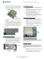
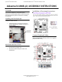
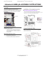
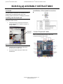
1
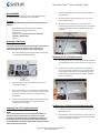
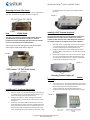
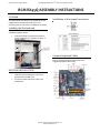
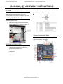
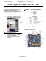
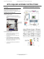
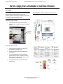
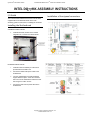
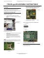
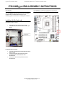
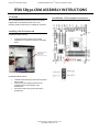
Assembly Guide
Model 526EX
450W 80PLUS
MotherBoard ReadySM System • MODEL 526EX
Radio Frequency Interference Notice (USA)
This equipment has been tested and found to comply with the limits for a Class B digital device, pursuant to Part 15 of the FCC Rules. These limits
are designed to provide reasonable protection against harmful interference in a residential installation. This equipment generates, uses, and can
radiate radio frequency energy and, if not installed and used in accordance with the instructions, may cause harmful interference to radio
communications. However, there is no guarantee that interference will not occur in a particular installation. If this equipment does cause
harmful interference to radio or television reception, which can be determined by turning the equipment off and on, the user is encouraged to
try to correct the interference by one or more of the following measures:
•
•
•
•
Reorient or relocate the receiving antenna.
Increase the separation between the equipment and the receiver.
Connect the equipment into an outlet on a circuit different from that to which the receiver is connected.
Consult the dealer or an experienced radio/TV technician for help.
Any changes or modifications not expressly approved by the grantee of this device could void the user’s authority to operate the equipment. The
customer is responsible for ensuring compliance of the modified product.
Only peripherals (computer input/output devices, terminals, printers, etc.) that comply with FCC class B limits may be attached to this computer
product. Operation with noncompliant peripherals is likely to result in interference to radio and TV reception.
All cables used to connect to peripherals must be shielded and grounded. Operation with cables, connected to peripherals that are not shielded
and grounded may result in interference to radio and TV reception.
Manufacturer: Systium® Technologies, LLC
New Hope, MN
763-537-3600
Contact:
Customer Support
NOTE
If a Class A device is installed within this system; then the system is to be considered a Class A system. In this configuration, operation of this
equipment in a residential area is likely to cause harmful interference.
Radio Frequency Interference Notice (CDN)
This Class B digital apparatus complies with Canadian ICES-003.
Cet appareil numérique de Ia classe B est conforme a Ia norme NMB-003 du Canada.
Declaration of the Manufacturer or Importer
nd
This system is compliant with Low Voltage Directive 2006/95/EC using the standard EN60950-1:2006+A11, 2 Ed., (IEC60950-1:2005).
This system is compliant with EU directive 2004/108/EC using the standards EN55022 and EN55024-1.
Disclaimer Statement
Systium® Technologies makes no warranty of any kind with regard to this material, including, but not limited to, the implied warranties of
merchantability and fitness for a particular purpose. Systium Technologies assumes no responsibility for any errors that may appear in this
document. Systium Technologies makes no commitment to update nor to keep current the information contained in this document. No part of
this document may be copied or reproduced in any form or by any means without prior written consent of Systium Technologies. † Third-party
brands and trademarks are the property of their respective owners.
Copyright © 2013, Systium® Technologies, LLC
PN: 91173-00 Rev 00
MotherBoard ReadySM System • MODEL 526EX
ASSEMBLY GUIDE
Assembly Safety Instructions
Before You Begin
Assembly of a computer system using this product shall be assembled
only by technically qualified personnel. Follow the instructions in the
document “Model 526EX Maintaining Regulatory Compliance” to meet
and maintain the safety and product regulatory compliance of this
product when assembling a computer system using this product.
WARNINGS
Read and adhere to all of these instructions and instructions
supplied with this assembly. Failure to follow these instructions
will result in voiding the product c regulatory compliance
statements. The computer system will most likely be
noncompliant with other regional product laws and regulations.
The procedures in this document assume familiarity with the general
terminology associated with personal computers and with the safety
practices and regulatory compliance required for using and modifying
electronic equipment.
WARNINGS
TO PREVENT ACCESS TO HIGH ELECTRICAL ENERGY PARTS, DO
NOT REMOVE THE COVERS WHILE THE SYSTEM IS POWERED
ON!
Do not open the power supply. The power supply in this
computer contains no user-serviceable parts. To avoid personal
injury or damage to your equipment, refer repair or
replacement of the power supply to qua 4fied technical
personnel only. All other areas and components of this
computer are considered user-accessible.
CAUTIONS
Electrostatic discharge (ESD) can damage disk drives, add-in
cards, and other components. Do the procedures described in
this chapter only at an ESD workstation. If such a station is not
available, you can provide some ESD protection by wearing an
anti-static wrist strap and attaching it to a metal part of the
chassis.
Add-in cards can be extremely sensitive to ESD and always
require careful handling. After removing the card from its
protective wrapper or from the computer, place the card flat on
a grounded, static-free surface, component side up. Use a
conductive foam pad (f available, but not the board wrapper Do
not slide the board over any surface.
For proper cooling and airflow, always close the chassis before
turning on the computer system. Operating the computer
system without the chassis closed can damage system parts.
1.
Be sure to follow each procedure in the correct order.
2.
Set up an equipment log to record the computer’s model and
serial numbers, all installed options, and other information
about the computer. This information must be saved as a
record of the product’s configuration and compliance with
the allowable configuration options.
3.
We recommend that you use an anti-static wrist strap and a
conductive foam pad when working on the computer.
4.
You will need a Phillips (#1 and #2 bits) screwdriver and
Needle Nose Pliers.
NOTE
The integration kit provides screws for the following:
• One lock tab
• One 6-32 TORX screw
• Two screw-in standoffs
• Four Hard Drive Mountings Screws
• Eight 6-32 Phillips Screws (motherboard)
• Eight M3 Phillips screws (Peripheral)
• Four Fan Mounting Screws
• Two Plastic Tie-wraps
• Four Stick-on Rubber Feet
• One Universal I/O Shield
Assembly Notes for Different Motherboards
The Model 526EX supports a number of different motherboards. A
number of the assembly step details are different for each specific
motherboard. This manual describes the steps required to complete
the base system assembly task. Any steps or figures specific to a
particular motherboard are noted with a reference to the assembly
instructions specific to that motherboard. If no other board
instructions are present, then the assembly step is consistent for all
motherboards.
NOTE
If the manual does not include information for your specific
motherboard check the Systium Technologies web site
www.systium.com Tech Support for updates to this manual.
Unpack the System
Systium Technologies offers MotherBoard Ready products in two
packaging configurations. The first is a reusable “End-User” ready
single package. The second is a hi-volume bulk package. The
instructions detailed are for the single package. Any differences in
procedures between the single package and bulk package are noted
within each section. The integration kits are the same for the single or
bulk package MotherBoard Ready Systems.
CAREFULLY UNPACK THE COMPUTER. Save the box and packaging
material for shipment to the customer. If components are missing
please contact your supplier or Systium Technologies.
Copyright © 2013, Systium® Technologies, LLC
PN: 91173-00 Rev 00
MotherBoard ReadySM System • MODEL 526EX
BULK PACKAGE
Please re-cycle the packaging. None of the bulk pack packaging is
designed for reuse when shipping to the end customer.
CONTENTS
The Model 526EX MotherBoard Ready System product contains the
following:
•
•
•
•
1.
The 5.25” peripheral carrier must be removed to install the
5.25 peripheral.
2.
Remove the three screws holding the 5.25” carrier to the
chassis. Refer to Figure 3
3.
Grasp the 5.25” carrier at the rear and pull the carrier
towards the rear of the chassis. Once the carrier is separated
from the chassis place it aside for installation of the 5.25”
peripheral.
Model 526EX Chassis with Power Supply Installed
North American Compliant Power Cord
Integration Kit
Quickstart Guide. (This manual must be included in
shipment to the End User.)
Manual
•
Removing a Side Cover
NOTE:
The system covers are protected with a plastic film. This film must be
removed from the top over before the unit is turned on. It is
recommended that the film be left in place during assembly.
1.
Remove the plastic bag protecting the chassis. Save the bag
for shipping the assembled computer.
2.
Remove the three screws securing the top cover to the
chassis. Refer to Figure 1
3.
Place a hand on each corner of the top cover. While putting
pressure on your fingers use your thumb to push the chassis
forward. This will cause the cover to separate from the
chassis base.
4.
Lift the top cover upwards and away from the chassis. Place
the cover to the side where it will not get scratched or
damaged before reassembly.
Removing the 3.5”Peripheral Carrier
1.
The 5.25” peripheral carrier screws must have been removed
by completing the previous section of instructions. See Figure
3.
2.
Pull back on the 3.5”carrier ejector level and release the
carrier from the chassis. Once the carrier is separated from
the front of the chassis the carrier can be lifted out of the
chassis. See Figure 4. Place the carrier a side for installation
of the 3.5” peripherals.
Installing the I/O Shield (Intel BOX Motherboard)
Removing the 5.25” Peripheral Carrier
1.
Locate the motherboard I/O shield supplied with the Intel
BOX motherboard.
2.
Place the lower surface of the I/O shield in the I/O opening in
the rear of the chassis. Ensure the I/O shield is fully inserted
into the opening. Refer to Figure 5.
NOTE:
The system must have a 5.25" external peripheral installed or an
EMI shield must be installed. Failure to install a 5.25" external
peripheral or EMI shield can result in EMI leakage that will result in
the computer system not meeting the product's EMC compliance.
A 5.25" EMI shield is not supplied with the Model 526EX and must be
ordered separately from Systium.
Copyright © 2013, Systium® Technologies, LLC
PN: 91173-00 Rev 00
MotherBoard ReadySM System • MODEL 526EX
3.
4.
Carefully press the top surface of the I/O shield into the I/O
opening. Be careful to only place pressure at the outer edges
of the I/O shield when pressing on the I/O shield.
Check that the I/O shield is fully inserted into the I/O
opening.
FIGURE 5
NOTE
Failure to properly install the I/O shield can result in EMI leakage that
will result in the computer system not meeting the product's EMC
compliance.
Installing a I/O Adapter (Optional)
NOTE
The Model 526EX system supports Motherboard with a variety of
I/O bus slots. The instructions to install the adapters are the
same. Care must be taken to install the adapter in the correct
I/O slot.
1.
2.
Remove the screw holding the I/O card hold-down bracket.
Rotate the bracket away from the chassis. Refer to Figure 6
3.
To remove the I/O slot cover, slide the cover upwards and
away from the back of the chassis.
4.
Refer to the PCI-E video adapter manual for any installation
or configuration steps that need to be completed before
installing the adapter into the chassis.
5.
Install the I/O adapter. Refer to the motherboard manual for
any motherboard specific installation instructions.
6.
Rotate the I/O hold-down bracket into place to secure the
I/O cards to the chassis. Secure the I/O card hold-down
bracket in place by installing the screw removed in step 1.
Installing the Motherboard
1.
Specific Motherboard may require the installation of a screwin standoff(s) in the chassis base to mount the motherboard
to. The standoff(s) are included with the integration kit. Refer
to the assembly instructions for the specific motherboard
being installed into the chassis.
2.
Following the instructions supplied with the motherboard,
install the CPU and memory. Ensure that the recommended
ESD protection guidelines are followed.
3.
Place the motherboard on the mounting supports. Carefully
slide the motherboard towards the rear of the chassis to
engage the motherboard connectors into the I/O shield
openings. Refer to the assembly instructions for the specific
motherboard being installed for a figure of the correct
installation of the motherboard into the I/O shield.
4.
Using the mounting screws supplied, mount the
motherboard to the chassis. Ensure that the motherboard is
fully inserted into the I/O shield while being tightened into
place.
5.
Connect the front panel connectors to the motherboard.
Refer to the motherboard manual for the correct positions.
Refer to assembly instructions for the specific motherboard
being installed for a figure of the correct installation of the
front panel connectors.
6.
Connect the ATX power connector to the motherboard. Refer
to the motherboard specific assembly instructions for any
additional motherboard power connections.
FIGURE 6
Removing the Front Bezel
The front bezel must be removed to allow removal of the 3.5”EMI
shield (if an external 3.5”device is being installed). The bezel must also
be removed for installation of the front panel USB.
1.
Grasp the front bezel at the outer edges. Refer to Figure 7.
2.
The bezel is held on by two spring clips. Pull the bezel away
from the front of the system to remove.
FIGURE 7
Copyright © 2013, Systium® Technologies, LLC
PN: 91173-00 Rev 00
MotherBoard ReadySM System • MODEL 526EX
the shouldered 6-32 mounting screws supplied. Refer to
Figure 10.
Removing the Bezel Filler Panels
To remove the peripheral filler panels push the mounting tabs toward
each other to release the panel from the bezel. See Figure 8.
FIGURE 8
FIGURE 10
Installing a 5.25” External Peripheral
Removing the 3.5”EMI Shield
NOTE
Only when a 3.5”external peripheral is being installed should the
3.5”EMI shield be removed. Failure to install a 3.5" external
peripheral can result in EMI leakage that will result in the computer
system not meeting the product's EMC compliance.
Remove the two screws holding the 3.5”EMI shield in place.
Remove the 3.5”EMI shield. Refer to Figure 9.
NOTE
The system must have one 5.25" external peripheral installed or an
EMI shield must be installed. Failure to install a 5.25" external
peripheral or EMI shield can result in EMI leakage that will result in
the computer system not meeting the product's EMC compliance.
1.
2.
FIGURE 9
3.
If the 5.25” carrier is not already removed you must remove
it. To remove the 5.25” carrier following the instructions in
the section “Removing the 5.25”Peripheral Carrier”.
Configure any jumpers or switch settings required by the
peripheral. Refer to the peripheral's user manual for specific
instructions.
Position the peripheral in the 5.25 carrier as shown in Figure
11. Line up the peripheral mounting holes with the carrier
mountings holes marked with a “3”. Using the supplied M3
screws, attach the peripheral to the carrier.
FIGURE 11
Installing a Second 3.5” Hard Drive Part Number
52635-00
1.
Installing a 3.5” Peripheral (Hard Drive)
1.
2.
3.
If the 3.5” carrier is not already removed you must remove it.
To remove the 3.5” carrier following the instructions in the
section “Removing the 3.5”Peripheral Carrier”.
Configure any jumpers or switch settings required by the
peripheral. Refer to the peripheral's user manual for specific
instructions.
Insert the 3.5” peripheral (HD Shown) into the carrier. The
power and signal connectors should be oriented towards the
rear of the chassis once the carrier is installed. Align the 3.5”
peripheral mounting screws with the mounting holes in the
carrier marked HD. Secure the peripheral to the carrier using
2.
If the 5.25” carrier is not already removed you must remove
it. To remove the 3.5” carrier following the instructions in the
section “Removing the 5.25”Peripheral Carrier”.
The second HD carrier must be attached to the 5.25
peripheral carrier before the HD is installed. Refer to Figure
12.
FIGURE 12
Copyright © 2013, Systium® Technologies, LLC
PN: 91173-00 Rev 00
MotherBoard ReadySM System • MODEL 526EX
3.
Position the second HD carrier such that the mounting tabs
locking into the mounting locations on the 5.25 peripheral
carrier. Secure the second HD carrier to the 5.25 peripheral
carrier using the two supplied screws. Refer to Figure 13.
FIGURE 13
Connect Peripheral Cables
1.
2.
3.
4.
Connect the SATA or IDE HD cable to the hard drive. Route
the cable along the bottom of the drive towards the front of
the chassis.
Connect the floppy cable to the floppy. The route the cable
over the HD cable and directly to the other board. Attached
the floppy cable to the motherboard.
Connect the SATA or IDE HD cable to the motherboard.
Route the cable over top the floppy cable.
Connect the IDE cable for the 5.25” peripheral to the
secondary IDE connector on the motherboard. Fold the cable
into a flat bundle to shorten up the cable. Position the drive
end of the cable to the rear of the chassis.
Install the 5.25”Peripheral Carrier
4.
5.
Configure any jumpers or switch settings required by the
peripheral. Refer to the peripheral's user manual for specific
instructions.
Insert the 3.5” peripheral (HD Shown) into the carrier. The
power and signal connectors should be oriented towards the
rear of the chassis once the carrier is installed. Align the 3.5”
peripheral mounting screws with the mounting holes in the
carrier marked HD. Secure the peripheral to the carrier using
the shouldered 6-32 mounting screws supplied. Refer to
Figure 14.
1.
2.
3.
Lower the 5.25” carrier into the chassis and insert the carrier
into the 5.25” opening in the front of the chassis. . The
carrier must fit inside the 5.25” chassis opening flanges. See
figure 16.
Line up the three mounting holes on the carrier with the
corresponding holes in the chassis. The mounting flange at
the side of the carrier is mounted on top of the 3.5” carrier
mounting tab. See Figure 16.
Connect the IDE cable to the 5.25 peripheral. See Figure 16.
FIGURE 14
FIGURE 16
Install the 3.5”Peripheral Carrier
1.
2.
3.
The 3.5” peripheral carrier is mounted in the chassis by two
guide rails and a mounting tab. The carrier must also fit
inside the 3.5” chassis opening flanges. See figure 15.
Lower the carrier into the chassis such that the carrier is held
between the two guides. Slide the carrier forwards to
position the floppy correctly in the 3.5” chassis opening.
Push the carrier forward until the ejector level latches into
place.
FIGURE 15
Connect the Peripheral Power Cables
Connect the peripheral power cables as required. Route the cables so
that there is no cables passing over top the CPU cooling fan. Use the
tie-wraps included in the integration kit to secure the cables together
to ensure clean routing.
Install Cover Lock Tab
NOTE
The Model 526EX utilizes a power supply with an Energy Hazard on
the 12V circuit. Compliance with CE requires installation of the cover
lock tab and a lock or the use of the 6-32 TORX screw to secure the
top cover.
1. Locate the locking tab and mounting screw in the accessory
package.
2. Position the locking tab in the notch in the power supply side
of the back of the chassis. Secure the locking tab to the
chassis using the screw supplied. Refer to Figure 17.
Copyright © 2013, Systium® Technologies, LLC
PN: 91173-00 Rev 00
MotherBoard ReadySM System • MODEL 526EX
FIGURE 17
The Model 526EX utilizes a power supply with an Energy Hazard on
the 12V circuit. Compliance with CE requires installation of the cover
lock tab and a lock or the use of the 6-32 TORX screw supplied to
secure the top cover.
Install the Chassis Feet - Desktop
1.
Install the Front USB Module (Optional)
NOTE
Perform this assembly step if the system requires the front USB ption
installed.
2.
3.
1.
2.
3.
4.
5.
Remove the front bezel. Refer to the previous section”
Removing the Front Bezel” for instructions.
Locate the front USB access cover. Remove the access cover
by inserting a flat screwdriver into the cover and flexing it
until the cover breaks away from the chassis. See Figure 18.
Remove the front USB module part # 52526-01C from the
box. Using the screws supplied with the USB module, secure
the USB module to the front of the chassis. See Figure 18.
Using the cable supplied with the front USB module connect
the USB module to the motherboard. Refer to the
instructions supplied with the motherboard for the front
panel USB connector.
Remove the USB filler panel from the bezel. Refer to Figure 8.
Reinstall the bezel. Line up the bezel mounting clips and push
the bezel towards the chassis to engage the mounting clips.
Turn the unit upside down. Place the unit on a surface that
will not scratch the top cover. Place the template supplied in
the accessory kit in one of the corners of the bottom surface
of the computer. Refer to Figure 19.
Remove the paper backing from the rubber foot and install
the foot sticky side down into the circular opening in the
template. Press on the foot to make sure it attaches firmly to
the bottom of the computer. Refer to Figure 19.
Repeat steps 1 & 2 to install the other three feet. Turn the
computer over and remove the protective cover from the top
cover.
FIGURE 19
Install the Chassis Feet - Tower
1.
2.
3.
FIGURE 18
4.
Remove the protective cover from the top cover.
Turn the computer such that the I/O card end of the
computer is at the top. Place the unit on a surface that will
not scratch the cover. Place the template supplied in the
accessory kit in one of the corners of the bottom surface of
the computer. Refer to Figure 19.
Remove the paper backing from the rubber foot and install
the foot sticky side down into the circular opening in the
template. Press on the foot to make sure it attaches firmly to
the bottom of the computer. Refer to Figure
Repeat steps 2 & 3 to install the other three feet.
Install the Top Cover
NOTE
Before installing the top side cover please check that all cables are
connected and no tools, screws or accessories are left inside the
chassis.
1.
2.
Position the cover down on top of the chassis about 1 inch
away to the rear of where the cover’s finally closed position.
Slide the cover forward to engage the cover locking tabs to
the chassis.
Attached the cover to the chassis using the three screws
used to initially secure the cover to the chassis. See Figure 1.
NOTE
Copyright © 2013, Systium® Technologies, LLC
PN: 91173-00 Rev 00
MotherBoard ReadySM System • MODEL 526EX
Power up the System
1.
2.
3.
4.
Connect the keyboard, mouse, monitor and any other
required peripheral for the correct operation of the
computer. Refer to the Model Guide for assistance in
connecting the peripherals to the computer.
Turn on the computer by pressing the power switch on the
front panel. Refer to the Quick Start Section of this manual
for more information.
Verify the operation of the POWER ON indicator on the front
panel. The LED should glow constantly when the computer is
turned on. Verify that the floppy LED turns on when the
system resets the floppy drive during the POST. Verify the
operation of the hard drive LED on the front panel. The LED
should turn on when the POST resets the hard drive or
attempts to boot the computer. Correct any problems
detected during the initial power up phase.
Test the complete operation of the computer using a known
good computer functional test program such as Intel’s Test
view. Install any required operating system or application
software.
NOTE
The computer must have all the required warning and information
lights functioning before shipping to the end user.
5.
Disconnect the computer from the peripherals used during
the testing phase. Package the computer using the original
packaging.
NOTE
You must include the End User Quick Start manual in the shipment to
the customer to maintain Regulatory Compliance.
Copyright © 2013, Systium® Technologies, LLC
PN: 91173-00 Rev 00
®
SySTIUM TECHNOLOGIES
MOTHERBOARD READY
SM
SYSTEM • MODEL 526EX
Advantech AIMB-567 ASSEMBLY INSTRUCTIONS
I/O Shield
Installation of front panel connectors
The Advantech AIMB-567 motherboard uses the
Advantech I/O shield supplied with the motherboard. Refer
to the main assembly guide for instructions on installing
the I/O shield.
Installing the Motherboard
STANDOFF INSTALLATION
1.
Install the standoff, (if required) included in the
chassis integration kit, in location 0 as shown in
the figure below.
Connect Peripheral Cables
Refer to the Model 526 Assembly Guide for the suggested
peripheral cable routing.
HEATSINK INSTALLATION
1.
Install the CPU fan heatsink per instructions
provided with the Intel Box set.
2.
Connect the heatsink fan power cable to the
motherboard.
Copyright © 2013, Systium® Technologies, LLC
526EX AIMB-567 AI Rev 1.0
®
SySTIUM TECHNOLOGIES
MOTHERBOARD READY
SM
SYSTEM • MODEL 526EX
Advantech AIMB-580 ASSEMBLY INSTRUCTIONS
motherboard.
I/O Shield
The Advantech AIMB-580 motherboard uses the
Advantech I/O shield supplied with the motherboard. Refer
to the main assembly guide for instructions on installing
the I/O shield.
Installation of front panel connectors
Stand Off
Installing the Motherboard
Connect Peripheral Cables
STANDOFF INSTALLATION
1.
Install the standoff, (if required) included in the
chassis integration kit, in location 0 as shown in
the figure below.
Refer to the Model 526 Assembly Guide for the suggested
peripheral cable routing.
HEATSINK INSTALLATION
1.
Install the CPU fan heatsink per instructions
provided with the Intel Box set.
2.
Connect the heatsink fan power cable to the
Copyright © 2013, Systium® Technologies, LLC
526EX AIMB-580 AI Rev 1.0
®
SySTIUM TECHNOLOGIES
MOTHERBOARD READY
SM
SYSTEM • MODEL 526EX
BCM RX35Q ASSEMBLY INSTRUCTIONS
I/O Shield
Installation of front panel connectors
The BCM RX35Q motherboard uses the BCM I/O shield
supplied with the motherboard. Refer to the main
assembly guide for instructions on installing the I/O shield.
Installing the Motherboard
STANDOFF INSTALLATION
1.
Install the standoff, (if required) included in the
chassis integration kit, in location 0 as shown in
the figure below.
Connect Peripheral Cables
Refer to the Model 526E Assembly Guide for the
suggested peripheral cable routing.
HEATSINK INSTALLATION
1.
Install the CPU fan heatsink per instructions
provided with the Intel Box set.
2.
Connect the heatsink fan power cable to the
motherboard.
Copyright © 2013, Systium® Technologies, LLC
526EX RX35Q AI Rev 1.0
®
SySTIUM TECHNOLOGIES
MOTHERBOARD READY
SM
SYSTEM • MODEL 526EX
BCM RX45Q ASSEMBLY INSTRUCTIONS
I/O Shield
The BCM RX45Q motherboard uses the BCM I/O shield
supplied with the motherboard. Refer to the main
assembly guide for instructions on installing the I/O shield.
Installation of front panel connectors
Installing the Motherboard
STANDOFF INSTALLATION
1.
Install the standoff, (if required) included in the
chassis integration kit, in location 0 as shown in
the figure below.
Connect Peripheral Cables
Refer to the Model 526E Assembly Guide for the
suggested peripheral cable routing.
HEATSINK INSTALLATION
1.
Install the CPU fan heatsink per instructions
provided with the Intel Box set.
2.
Connect the heatsink fan power cable to the
motherboard.
Copyright © 2013, Systium® Technologies, LLC
526EX RX45Q AI Rev 1.0
®
SySTIUM TECHNOLOGIES
MOTHERBOARD READY
SM
SYSTEM • MODEL 526EX
BCM RX67QV ASSEMBLY INSTRUCTIONS
I/O Shield
The BCM RX67Q motherboard uses the BCM I/O shield
supplied with the motherboard. Refer to the main
assembly guide for instructions on installing the I/O shield.
Installation of front panel connectors
Installing the Motherboard
STANDOFF INSTALLATION
1.
Install the standoff, (if required) included in the
chassis integration kit, in location 0 as shown in
the figure below.
Connect Peripheral Cables
Refer to the Model 526E Assembly Guide for the
suggested peripheral cable routing.
HEATSINK INSTALLATION
1.
Install the CPU fan heatsink per instructions
provided with the Intel Box set.
2.
Connect the heat sink fan power cable to the
motherboard.
Copyright © 2013, Systium® Technologies, LLC
526EX RX67Q AI Rev 1.0
®
SySTIUM TECHNOLOGIES
MOTHERBOARD READY
SM
SYSTEM • MODEL 526EX
BCM RX965QV ASSEMBLY INSTRUCTIONS
I/O Shield
The BCM RX67Q motherboard uses the BCM I/O shield
supplied with the motherboard. Refer to the main
assembly guide for instructions on installing the I/O shield.
Installation of front panel connectors
Installing the Motherboard
STANDOFF INSTALLATION
1.
Install the standoff, (if required) included in the
chassis integration kit, in location 0 as shown in
the figure below.
Connect Peripheral Cables
Refer to the Model 526E Assembly Guide for the
suggested peripheral cable routing.
HEATSINK INSTALLATION
1.
Install the CPU fan heatsink per instructions
provided with the Intel Box set.
2.
Connect the heatsink fan power cable to the
motherboard.
Copyright © 2013, Systium® Technologies, LLC
526EX RX965QV AI Rev 1.0
®
SySTIUM TECHNOLOGIES
MOTHERBOARD READY
SM
SYSTEM • MODEL 526EX
INTEL DH55TC ASSEMBLY INSTRUCTIONS
.
I/O Shield
Installation of front panel connectors
The Intel DH55TC motherboard uses the Intel I/O shield
supplied with the motherboard. Refer to the main
assembly guide for instructions on installing the I/O shield.
Installing the Motherboard
STANDOFF INSTALLATION
1.
Install the standoff, included in the chassis
integration kit, in location 0 as shown in the figure
below.
HEATSINK INSTALLATION
1.
Install the CPU fan heatsink per instructions
provided with the Intel Box set.
2.
Connect the heatsink fan power cable to the
motherboard.
3.
Turn the motherboard over while holding the
support bracket in place. Place the new heat
sink mount on the motherboard. Attach the heat
sink using the 4 built-in screws.
4.
Connect the heat sink fan power cable to the
motherboard.
Copyright © 2013, Systium® Technologies, LLC
526EX DH55TC AI Rev 1.0
®
SySTIUM TECHNOLOGIES
MOTHERBOARD READY
SM
SYSTEM • MODEL 526EX
INTEL DQ67OW ASSEMBLY INSTRUCTIONS
Installation of front panel connectors
I/O Shield
The Intel DQ67OW motherboard uses the Intel I/O shield
supplied with the motherboard. Refer to the main
assembly guide for instructions on installing the I/O shield.
Installing the Motherboard
STANDOFF INSTALLATION
1.
Install the standoff, included in the chassis
integration kit, in location 0 as shown in the figure
below.
HEATSINK INSTALLATION
1.
Install the CPU fan heatsink per instructions
provided with the Intel Box set.
2.
Connect the heatsink fan power cable to the
motherboard.
3.
Turn the motherboard over while holding the
support bracket in place. Place the new heat
sink mount on the motherboard. Attach the heat
sink using the 4 built-in screws.
4.
Connect the heat sink fan power cable to the
motherboard.
Copyright © 2013, Systium® Technologies, LLC
526EX DQ67OW AI Rev 1.0
®
SySTIUM TECHNOLOGIES
MOTHERBOARD READY
SM
SYSTEM • MODEL 526EX
INTEL DQ67SW ASSEMBLY INSTRUCTIONS
I/O Shield
The Intel DQ67SW motherboard uses the Intel I/O shield
supplied with the motherboard. Refer to the main
assembly guide for instructions on installing the I/O shield.
Installation of front panel connectors
Installing the Motherboard
STANDOFF INSTALLATION
1.
Install the standoff, included in the chassis
integration kit, in location 0 as shown in the figure
below.
HEATSINK INSTALLATION
1.
Install the CPU fan heatsink per instructions
provided with the Intel Box set.
2.
Connect the heatsink fan power cable to the
motherboard.
3.
Turn the motherboard over while holding the
support bracket in place. Place the new heat
sink mount on the motherboard. Attach the heat
sink using the 4 built-in screws.
4.
Connect the heat sink fan power cable to the
motherboard
Copyright © 2013, Systium® Technologies, LLC
526EX DQ67SW AI Rev 1.0
®
SySTIUM TECHNOLOGIES
MOTHERBOARD READY
SM
SYSTEM • MODEL 526EX
INTEL DQ77MK ASSEMBLY INSTRUCTIONS
I/O Shield
Installation of front panel connectors
The Intel DQ77MK motherboard uses the Intel I/O shield
supplied with the motherboard. Refer to the main
assembly guide for instructions on installing the I/O shield.
Installing the Motherboard
STANDOFF INSTALLATION
1.
Install the standoff, included in the chassis
integration kit, in location 0 as shown below.
HEATSINK INSTALLATION
1.
Install the CPU fan heatsink per instructions
provided with the Intel Box set.
2.
Connect the heatsink fan power cable to the
motherboard.
3.
Turn the motherboard over while holding the
support bracket in place. Place the new heat
sink mount on the motherboard. Attach the heat
sink using the 4 built-in screws.
4.
Connect the heat sink fan power cable to the
motherboard.
Copyright © 2013, Systium® Technologies, LLC
526EX DQ77MK AI Rev 1.0
®
SySTIUM TECHNOLOGIES
MOTHERBOARD READY
SM
SYSTEM • MODEL 526EX
ITOX BL330-BR ASSEMBLY INSTRUCTIONS
3.
I/O Shield
Turn the motherboard over while holding the
support bracket in place. Place the new heat sink
mount on the motherboard. Attach the heatsink
using the 4 built-in screws. See Figure 2.
The ITOX BL330-BR motherboard uses the I/O shield
supplied with the motherboard. Refer to the main
assembly guide for instructions on installing the I/O shield.
FIGURE 2
Installing the Motherboard
STANDOFF INSTALLATION
1.
Install the standoff, included in the chassis
integration kit, in location 0 as shown in the figure
below.
4.
Connect the heatsink fan power cable to the
motherboard. Refer to Figure 2.
INSTALLATION OF FRONT PANEL CONNECTORS
HEATSINK INSTALLATION
1.
2.
Install the CPU following the instructions provided
with the CPU.
Insert the heat sink support bracket into the
motherboard from the underside of the
motherboard. The standoffs on the bracket are
inserted into the holes in the motherboard. Refer
to Figure 1.
NOTE
Make sure the top surface of the heat sink support bracket has
the mylar insulator. Failure to have the insulator in place will
result in the board not working.
FIGURE 1
Connect Peripheral Cables
Refer to the Model 526 Assembly Guide for the suggested
peripheral cable routing.
Copyright © 2013, Systium® Technologies, LLC
526EX BL330-BR AI Rev 1.0
®
SySTIUM TECHNOLOGIES
MOTHERBOARD READY
SM
SYSTEM • MODEL 526EX
ITOX EL330-DR ASSEMBLY INSTRUCTIONS
I/O Shield
3.
The ITOX EL330-DR motherboard uses the I/O shield
supplied with the motherboard. Refer to the main
assembly guide for instructions on installing the I/O shield.
Turn the motherboard over while holding the
support bracket in place. Place the new heat sink
mount on the motherboard. Attach the heatsink
using the 4 built-in screws. See Figure 2.
FIGURE 2
Installing the Motherboard
STANDOFF INSTALLATION
1.
Install the standoff, included in the chassis
integration kit, in location 0 as shown in the figure
below.
4.
Stand Off
Connect the heatsink fan power cable to the
motherboard. Refer to Figure 2.
INSTALLATION OF FRONT PANEL CONNECTORS
HEATSINK INSTALLATION
1.
2.
Install the CPU following the instructions provided
with the CPU.
Insert the heat sink support bracket into the
motherboard from the underside of the
motherboard. The standoffs on the bracket are
inserted into the holes in the motherboard. Refer
to Figure 1.
NOTE
Make sure the top surface of the heat sink support bracket has
the mylar insulator. Failure to have the insulator in place will
result in the board not working.
FIGURE 1
Connect Peripheral Cables
Refer to the Model 526E Assembly Guide for the
suggested peripheral cable routing.
Copyright © 2013, Systium® Technologies, LLC
526EX EL330-DR AI Rev 1.0
®
SySTIUM TECHNOLOGIES
MOTHERBOARD READY
SM
SYSTEM • MODEL 526EX
ITOX MB330-CRM ASSEMBLY INSTRUCTIONS
I/O Shield
Installation of front panel connectors
The ITOX MB330-CRM motherboard uses the I/O shield
supplied with the motherboard. Refer to the main
assembly guide for instructions on installing the I/O shield.
Installing the Motherboard
STANDOFF INSTALLATION
•
Install the standoff, included in the chassis
integration kit, in location 0 as shown in the figure
below.
HEATSINK INSTALLATION
•
•
•
Install the CPU following the instructions provided
with the CPU.
Insert the heat sink support bracket into the
motherboard from the underside of the
motherboard.
Connect the heat sink fan power cable to the
motherboard.
Copyright © 2013, Systium® Technologies, LLC
526EX MB330-CRM AI Rev 1.0
®
SySTIUM TECHNOLOGIES
MOTHERBOARD READY
SM
SYSTEM • MODEL 526EX
ITOX SB330-CRM ASSEMBLY INSTRUCTIONS
I/O Shield
Installation of front panel connectors
The ITOX SB330-CRM motherboard uses the I/O shield
supplied with the motherboard. Refer to the main
assembly guide for instructions on installing the I/O shield.
Installing the Motherboard
STANDOFF INSTALLATION
•
Install the standoff, included in the chassis
integration kit, in location 0 as shown in the figure
below.
HEATSINK INSTALLATION
•
•
•
Install the CPU following the instructions provided
with the CPU.
Insert the heat sink support bracket into the
motherboard from the underside of the
motherboard.
Connect the heat sink fan power cable to the
motherboard.
Copyright © 2013, Systium® Technologies, LLC
526EX MB331-CRM AI Rev 1.0
®
SySTIUM TECHNOLOGIES
MOTHERBOARD READY
SM
SYSTEM • MODEL 526EX
ITOX SB330-CRM ASSEMBLY INSTRUCTIONS
I/O Shield
Installation of front panel connectors
The Itox SB330-CRM motherboard uses the Intel I/O
shield supplied with the motherboard. Refer to the main
assembly guide for instructions on installing the I/O shield.
Installing the Motherboard
STANDOFF INSTALLATION
1.
Install the standoff, included in the chassis
integration kit, in location 0 as shown in the figure
below.
HEATSINK INSTALLATION
1.
Install the CPU fan heatsink per instructions
provided with the Intel Box set.
2.
Connect the heatsink fan power cable to the
motherboard.
3.
Turn the motherboard over while holding the
support bracket in place. Place the new heat
sink mount on the motherboard. Attach the heat
sink using the 4 built-in screws.
4.
Connect the heat sink fan power cable to the
motherboard.
Copyright © 2013, Systium® Technologies, LLC
526EX SB330-CRM AI Rev 1.0
MODEL 526EX MAINTAINING REGULATORY COMPLIANCE
WARNING
Read and adhere to all of these instructions supplied for the Model 526EX system. Failure to follow these instructions will result in voiding the
product’s regulatory compliance statements. Note that the computer system may be noncompliant with other regional product laws and
regulations.
Critical Components: To maintain the Model 526EX CSA listing and Model 526EX compliance to other regulatory certifications and/or declarations the
following Critical Components must be used.
The Model 526EX product is a Critical Component. The SySTIUM® Model 526EX must be used without modification to the cooling fans or the chassis
enclosure. The power supplies listed below are included with the Model 526EX. Any Model 526EX power supply substitution or modification will
invalidate the Model 526EX regulatory compliance.
One of the motherboards listed in the table below must be used with the Model 526EX. Use of any other motherboard will invalidate the Model 526EX
regulatory compliance. The integrator must use the heat sink listed as required to ensure regulatory compliance. The table below was constructed using
a CPU no greater than 95W TDP. Using a higher wattage CPU will invalidate the Model 526EX regulatory compliance.
MFG
Motherboard
Intel
DG41TY
Intel
DH55TC
Intel
DQ67SW
Intel
DQ77MK
Advantech
AIMB-580
Advantech
AIMB-567
BCM
RX35Q
BCM
RX965QV
BCM
RX45Q
BCM
RX67Q
ITOX
BL330-BR
ITOX
EL330-DR
ITOX
MB330-CRM
ITOX
ITOX
MB331-CRM
SB330-CRM
Notes
Power Supplies
ST-450SFX
ST-450SFX
ST-450SFX
ST-450SFX
Heat Sink Required
SySTIUM 10304-00C
or 10312-25
All CPU’s to:
Intel Supplied
3.4GHz
SySTIUM 10312-25
3.4GHz
SySTIUM 10312-25
3.4GHz
ST-450SFX
SySTIUM 10312-25
ST-450SFX
SySTIUM 10304-00C
or 10312-25
SySTIUM 10304-00C
or 10312-25
SySTIUM 10304-00C
or 10312-25
SySTIUM 10304-00C
or 10312-25
SySTIUM 10312-25
ST-450SFX
ST-450SFX
ST-450SFX
ST-450SFX
ST-450SFX
ST-450SFX
ST-450SFX
ST-450SFX
ST-450SFX
SySTIUM 10304-00C
or 10312-25
SySTIUM 10304-00C
or 10312-25
SySTIUM 10304-00C
or 10312-25
SySTIUM 10304-00C
or 10312-25
SySTIUM 10304-00C
or 10312-25
3.33 GHz
3.4GHz
3.4GHz
3.4GHz
3.8GHz
3.4GHz
3.4GHz
3.4GHz
3.4GHz
3.4GHz
3.4GHz
3.4GHz
Optional Components: In addition to the required Critical Components listed above Optional Components may be integrated by the
assembler/integrator. Optional Components include peripherals (HDD, SSD, optical drives, etc.) and add in /add-on adapters (PCI, PCI-e, USB
devices, etc.). The assembler/integrator assumes responsibility for ensuring the Optional Components meet Model 526EX regulatory compliance.
ADAPTERS
The Model 526EX is designed to support only half-length PCI or PCI-e adapters. Installed adapters must be CSA, UL or
TUV Listed or Recognized, FCC Class B compliant and CE Marked.
PERIPHERALS
Installed peripherals must be CSA, UL or TUV Listed or Recognized, FCC Class B compliant and CE Marked.
NOTE: If a Class A device is installed within this system, then the system is considered a Class A system with respect to the FCC and CE
certification.
Copyright © 2013, SySTIUM® Technologies, LLC
PN: 91608-00 Rev00
1
NOTE: Effective January 1, 2013 the CE Mark also includes Environmental Conformance Requirements (RoHSII). SySTIUM® maintains a
RoHSII technical file for the Model 526EX (and any Critical Component or Optional Component supplied by SySTIUM®) The SySTIUM®
Technical File is available upon request and signed NDA. The assembler/integrator assumes responsibility to maintain a CE compliant technical
file on all Critical Components and on all Optional Components that were integrated into the Model 526EX to ensure compliance with the CE
mark.
NOTE: The information documented above is updated as required on the SySTIUM® Website (www.SySTIUM.com). Please check the website
for information on new supported Critical Components and/or processor speeds.
Validating Power Budget – It is the responsibility of the assembler/integrator to validate that the Model 526EX maximum power budget is not being
exceeded. The computer’s assembled configuration maximum power load cannot exceed the safety certification configuration maximum power load.
Note that the power supply’s output ratings are higher than the Model 526EX system safety certification ratings. Customer configurations must be
checked to ensure that the system’s safety certification loads are not exceeded; otherwise the CSA safety certification is null and void.
The power calculation table is provided below to assist in verifying that the assembled system remains compliant with the Model 526EX maximum power
load configuration to maintain CSA safety certification. It is recommended that a copy of the filled out table be filled with the assembly plan for the
configuration and be available for CSA safety inspection when necessary.
NOTE: It the assemblers/integrators responsibility to determine and validate the amperage and power ratings of any Optional Components (Add-in
PCI / PCIe / USB loads and verify that they fall within the Add-In Total Load line item provided. The 72W, 12V portion of the add-in total load is
sufficient for most add-in video cards.
The final system configuration’s power budget must fall within the Safety Maximum to maintain compliance.
450W supply – EXAMPLE POWER BUDGET – CONFORMING TO THE SAFETY MAXIMUMS
DEVICE
MAX WATTAGE
12V A
5V A
3.3V A
5V sb A
OPTICAL DRIVE
25.5
1.5
1.5
0
0
HDD 1
12.75
0.75
0.75
0
0
HDD2
12.75
0.75
0.75
0
0
CPU
96
8
0
0
0
MB / MEM / FAN(s)
46
1.5
4
2
0.25
Add-in PCI/PCIex/USB
Total Load
129.45
6
5.3
9
0.25
System Total – PSU MAX
Per SAFETY CERTIFICATION
322.45
18.5
12.3
11
0.5
NOTE
The peripheral power ratings are typically listed on the product identification label on the peripheral. The manufacturer’s specifications are
another source of this information. The load wattage is determined by multiplying the peripheral supply voltage by the peripheral’s maximum
current draw for that voltage. For dual voltage peripherals the total load wattage is the sum of each supply voltage’s wattage.
NOTE
Use Only for Intended Applications
This product was evaluated as Information Technology Equipment (ITE) that may be installed in offices, homes and similar locations. The use of
this product for other Product Safety Categories or Environments other than ITE may require further evaluation. Examples of other Product
Safety Categories are Medical Instrumentation or Control and Test Equipment. Check with your Local Product Safety Agency for further
information.
Copyright © 2013, SySTIUM® Technologies, LLC
PN: 91608-00 Rev00
2
REGULATORY INFORMATION
A computer system, when correctly configured and assembled as instructed in this document, meets the following safety and EMC regulations.
SAFETY COMPLIANCE
UL 60950-1 Second Edition; CSA60950-1-07 Second Edition Amendment 1:2011
Information Technology Equipment - Safety - Part 1: General Requirements
EN 60950- 1:2006/A11:2009/A1:2010/A12:2011;
The Standard for Safety of Information Technology Equipment including Electrical Business Equipment. (European Union)
“EN 60950 compliance”
IEC 60950-1:2005 (2nd Edition); Am 1:2009
The Standard for Safety of Information Technology Equipment including Electrical Business Equipment. (International)
EMC COMPLIANCE
FCC Class B
Title 47 of the Code of Federal Regulations, Parts 2 & 15, Subpart B, pertaining to unintentional radiators. (USA) “EMI regulations” “FCC
compliance”
CISPR 22; 2009+A1:2010
Limits and methods of measurement of Radio Interference Characteristics of Information Technology Equipment. (International) “CISPR
22compliance”
EN 55022:2010
Limits and methods of measurement of Radio Interference Characteristics of Information Technology Equipment. (Europe)
“EN 55022 compliance”
EN 55024:2010
ITE Immunity Standard;
ICES-003:2012
Interference-Causing Equipment Standard, Digital Apparatus. (Canada)
ENVIRONMENTAL COMPLIANCE
RoHSII Directive 2011/65/EU
Copyright © 2013, SySTIUM® Technologies, LLC
PN: 91608-00 Rev00
3