1
OPERATING INSTRUCTIONS
Read this manual carefully before you use this product and keep it handy for future
reference.
For safety, please follow the instructions in this manual.
RICOH COMPANY, LTD.
15-5, 1 chome, Minami-Aoyama, Minato-ku, Tokyo
Telephone: Tokyo 3479-3111
RICOH CORPORATION
CALLING FOR SERVICE
For service in the United States, please call:
1–800–RICOH 38 (1–800–742–6438)
U.S.A.
RICOH CORPORATION
5 Dedrick Place
West Caldwell, New Jersey 07006
Phone: +1-973-882-2000
Spain
RICOH ESPAÑA S.A.
Avda. Litoral Mar, 12-14,
08005 Barcelona
Phone: +34-(0)93-295-7600
The Netherlands
RICOH EUROPE B.V.
Groenelaan 3, 1186 AA, Amstelveen
Phone: +31-(0)20-5474111
Italy
RICOH ITALIA SpA
Via della Metallurgia 12,
37139 Verona
Phone: +39-(0)45-8181500
United Kingdom
RICOH UK LTD.
Ricoh House,
1 Plane Tree Crescent, Feltham,
Middlesex, TW13 7HG
Phone: +44-(0)181-261-4000
Germany
RICOH DEUTSCHLAND GmbH
Mergenthalerallee 38-40,
65760 Eschborn
Phone: +49-(0)6196-9060
France
RICOH FRANCE S.A.
383, Avenue du Général de Gaulle
BP 307-92143 Clamart Cedex
Phone: +33-(0)1-40-94-38-38
Model number: G031–17, G032–17
Printed in Japan
UE USA G031-8607A
Hong Kong
RICOH HONG KONG LTD.
23/F., China Overseas Building,
139, Hennessy Road,
Wan Chai, Hong Kong
Phone: +852-2862-2888
Singapore
RICOH ASIA PACIFIC PTE.LTD.
260 Orchard Road,
#15-01/02 The Heeren,
Singapore 238855
Phone: +65-830-5888
OPERATING INSTRUCTIONS
Overseas Affiliates
Introduction
This manual contains detailed instructions on the operation and maintenance of this machine. To get
maximum versatility from this machine all operators should carefully read and follow the instructions in
this manual. Please keep this manual in a handy place near the machine.
Please read the Safety Information before using this machine. It contains important information related
to USER SAFETY and PREVENTING EQUIPMENT PROBLEMS.
Notes:
The model names of the machines do not appear in the following pages. Check the model name of your
machine before reading this manual. (For details, see P.2 “Type 1 Printer”, P.5 “Type 2 Printer”.)
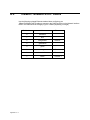
Descriptions in this manual
Model name
Type 1 Printer
RICOH LASER AP2000
Type 2 Printer
RICOH LASER AP1400
Descriptions without the note for identifying the type of the printer are common for both models. Certain
types might not be available in some countries. For details, please contact your local dealer.
Power Source
RICOH LASER AP2000: 120 V, 60 Hz, 8.0 A or more
RICOH LASER AP1400: 120 V, 60 Hz, 6.0 A or more
Please be sure to connect the power cord to a power source as above.
Operator Safety:
This machine is considered a CDRH class I laser device, safe for office/ EDP use. The machine contains 5-milliwat, 760 - 800 nanometer wavelength, GaAIAs laser diode. Direct (or indirect reflected) eye
contact with the laser beam might cause serious eye damage. Safety precautions and interlock mechanisms have been designed to prevent any possible laser beam exposure to the operator.
Laser Safety:
The Center for Devices and Radiological Health (CDRH) prohibits the repair of laser-based optical unit
in the field. The optical housing unit can only be repaired in a factory or at a location with the requisite
equipment. The laser subsystem is replaceable in the field by a qualified Customer Engineer. The laser
chassis is not repairable in the field. Customer engineers are therefore directed to return all chassis
and laser subsystems to the factory or service depot when replacement or the optical subsystem is required.
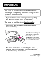
Important
Parts of this manual are subject to change without prior notice. In no event will the company be liable
for direct, indirect, special, incidental, or consequential damages as a result of handling or operating
the machine.
Caution:
Use of controls or adjustment or performance of procedures other than those specified in this manual
might result in hazardous radiation exposure.
Do not attempt any maintenance or troubleshooting other than that mentioned in this manual. This machine contains a laser beam generator and direct exposure to laser beams can cause permanent eye
damage.
Two kinds of size notation are employed in this manual. With this machine refer to the Inch version.
Ricoh shall not be responsible for any damage or expense that might result from the use of parts other
than genuine Ricoh parts in your Ricoh office product.
For good copy quality, Ricoh recommends that you use genuine Ricoh toner.
Note to users in the United States of America
Notice:
This equipment has been tested and found to comply with the limits for a Class B digital device, pursuant to Part 15
of the FCC Rules. These limits are designed to provide reasonable protection against harmful interference in a residential installation. This equipment generates, uses and can radiate radio frequency energy and, if not installed and
used in accordance with the instructions, may cause harmful interference to radio communications.
However, there is no guarantee that interference will not occur in a particular installation. If this equipment does
cause harmful interference to radio or television reception, which can be determined by turning the equipment off
and on, the user is encouraged to try to correct the interference by one more of the following measures:
Reorient or relocate the receiving antenna.
Increase the separation between the equipment and receiver.
Connect the equipment into an outlet on a circuit different from that to which the receiver is connected.
Consult the dealer or an experienced radio/TV technician for help.
Warning
Changes or modifications not expressly approved by the party responsible for compliance could void the user's authority to operate the equipment.
Caution (in case of 100BaseTX environment):
Properly shielded and grounded cables (STP) and connectors must be used for connections to host computer (and/
or peripheral) in order to meet FCC emission limits.
Declaration of Conformity
Product Name: Printer
Model Number: G031–17, G032–17
Responsible party: Ricoh Corporation
Address: 5 Dedrick Place, West Caldwell, NJ 07006
Telephone number: 973-882-2000
This device complies with part 15 of FCC Rules.
Operation is subject to the following two conditions:
1. This device may not cause harmful interference, and
2. this device must accept any interference received,
including interference that may cause undesired operation.
Properly shielded cables must be used for connections to host computer (and/or peripheral) in order to
meet FCC emission limits.
Network interface cable with ferrite core must be used for RF interference suppression.
Note to users in Canada
Note:
This Class B digital apparatus complies with Canadian ICES-003.
Remarque concernant les utilisateurs au Canada
Avertissement:
Cet appareil numérique de la classe B est conforme à la norme NMB-003 du Canada.
In accordance with IEC Standard 417, this machine uses the following symbols for the main power switch:
a means POWER ON.
b means POWER OFF.
Copyright © 1999 Ricoh Co., Ltd.
Introduction
This manual contains detailed instructions on the operation and maintenance of this machine. To get
maximum versatility from this machine all operators should carefully read and follow the instructions in
this manual. Please keep this manual in a handy place near the machine.
Please read the Safety Information before using this machine. It contains important information related
to USER SAFETY and PREVENTING EQUIPMENT PROBLEMS.
Notes:
The model names of the machines do not appear in the following pages. Check the model name of your
machine before reading this manual. (For details, see P.2 “Type 1 Printer”, P.5 “Type 2 Printer”.)
Descriptions in this manual
Model name
Type 1 Printer
SAVIN SLP20
Type 2 Printer
SAVIN SLP14
Descriptions without the note for identifying the type of the printer are common for both models. Certain
types might not be available in some countries. For details, please contact your local dealer.
Power Source
SAVIN SLP20: 120 V, 60 Hz, 8.0 A or more
SAVIN SLP14: 120 V, 60 Hz, 6.0 A or more
Please be sure to connect the power cord to a power source as above.
Operator Safety:
This machine is considered a CDRH class I laser device, safe for office/ EDP use. The machine contains 5-milliwat, 760 - 800 nanometer wavelength, GaAIAs laser diode. Direct (or indirect reflected) eye
contact with the laser beam might cause serious eye damage. Safety precautions and interlock mechanisms have been designed to prevent any possible laser beam exposure to the operator.
Laser Safety:
The Center for Devices and Radiological Health (CDRH) prohibits the repair of laser-based optical unit
in the field. The optical housing unit can only be repaired in a factory or at a location with the requisite
equipment. The laser subsystem is replaceable in the field by a qualified Customer Engineer. The laser
chassis is not repairable in the field. Customer engineers are therefore directed to return all chassis
and laser subsystems to the factory or service depot when replacement or the optical subsystem is required.
Important
Parts of this manual are subject to change without prior notice. In no event will the company be liable
for direct, indirect, special, incidental, or consequential damages as a result of handling or operating
the machine.
Caution:
Use of controls or adjustment or performance of procedures other than those specified in this manual
might result in hazardous radiation exposure.
Do not attempt any maintenance or troubleshooting other than that mentioned in this manual. This machine contains a laser beam generator and direct exposure to laser beams can cause permanent eye
damage.
Two kinds of size notation are employed in this manual. With this machine refer to the Inch version.
Savin shall not be responsible for any damage or expense that might result from the use of parts other
than genuine Savin parts in your Savin office product.
For good copy quality, Savin recommends that you use genuine Savin toner.
Note to users in the United States of America
Notice:
This equipment has been tested and found to comply with the limits for a Class B digital device, pursuant to Part 15
of the FCC Rules. These limits are designed to provide reasonable protection against harmful interference in a residential installation. This equipment generates, uses and can radiate radio frequency energy and, if not installed and
used in accordance with the instructions, may cause harmful interference to radio communications.
However, there is no guarantee that interference will not occur in a particular installation. If this equipment does
cause harmful interference to radio or television reception, which can be determined by turning the equipment off
and on, the user is encouraged to try to correct the interference by one more of the following measures:
Reorient or relocate the receiving antenna.
Increase the separation between the equipment and receiver.
Connect the equipment into an outlet on a circuit different from that to which the receiver is connected.
Consult the dealer or an experienced radio/TV technician for help.
Warning
Changes or modifications not expressly approved by the party responsible for compliance could void the user's authority to operate the equipment.
Caution (in case of 100BaseTX environment):
Properly shielded and grounded cables (STP) and connectors must be used for connections to host computer (and/
or peripheral) in order to meet FCC emission limits.
Declaration of Conformity
Product Name: Printer
Model Number: G031–17, G032–17
Responsible party: Ricoh Corporation
Address: 5 Dedrick Place, West Caldwell, NJ 07006
Telephone number: 973-882-2000
This device complies with part 15 of FCC Rules.
Operation is subject to the following two conditions:
1. This device may not cause harmful interference, and
2. this device must accept any interference received,
including interference that may cause undesired operation.
Properly shielded cables must be used for connections to host computer (and/or peripheral) in order to
meet FCC emission limits.
Network interface cable with ferrite core must be used for RF interference suppression.
Note to users in Canada
Note:
This Class B digital apparatus complies with Canadian ICES-003.
Remarque concernant les utilisateurs au Canada
Avertissement:
Cet appareil numérique de la classe B est conforme à la norme NMB-003 du Canada.
In accordance with IEC Standard 417, this machine uses the following symbols for the main power switch:
a means POWER ON.
b means POWER OFF.
Introduction
This manual contains detailed instructions on the operation and maintenance of this machine. To get
maximum versatility from this machine all operators should carefully read and follow the instructions in
this manual. Please keep this manual in a handy place near the machine.
Please read the Safety Information before using this machine. It contains important information related
to USER SAFETY and PREVENTING EQUIPMENT PROBLEMS.
Notes:
The model names of the machines do not appear in the following pages. Check the model name of your
machine before reading this manual. (For details, see P.2 “Type 1 Printer”, P.5 “Type 2 Printer”.)
Descriptions in this manual
Model name
Type 1 Printer
Gestetner P7020
Type 2 Printer
Gestetner P7014
Descriptions without the note for identifying the type of the printer are common for both models. Certain
types might not be available in some countries. For details, please contact your local dealer.
Power Source
Gestetner P7020: 120 V, 60 Hz, 8.0 A or more
Gestetner P7014: 120 V, 60 Hz, 6.0 A or more
Please be sure to connect the power cord to a power source as above.
Operator Safety:
This machine is considered a CDRH class I laser device, safe for office/ EDP use. The machine contains 5-milliwat, 760 - 800 nanometer wavelength, GaAIAs laser diode. Direct (or indirect reflected) eye
contact with the laser beam might cause serious eye damage. Safety precautions and interlock mechanisms have been designed to prevent any possible laser beam exposure to the operator.
Laser Safety:
The Center for Devices and Radiological Health (CDRH) prohibits the repair of laser-based optical unit
in the field. The optical housing unit can only be repaired in a factory or at a location with the requisite
equipment. The laser subsystem is replaceable in the field by a qualified Customer Engineer. The laser
chassis is not repairable in the field. Customer engineers are therefore directed to return all chassis
and laser subsystems to the factory or service depot when replacement or the optical subsystem is required.
Important
Parts of this manual are subject to change without prior notice. In no event will the company be liable
for direct, indirect, special, incidental, or consequential damages as a result of handling or operating
the machine.
Caution:
Use of controls or adjustment or performance of procedures other than those specified in this manual
might result in hazardous radiation exposure.
Do not attempt any maintenance or troubleshooting other than that mentioned in this manual. This machine contains a laser beam generator and direct exposure to laser beams can cause permanent eye
damage.
Two kinds of size notation are employed in this manual. With this machine refer to the Inch version.
Gestetner shall not be responsible for any damage or expense that might result from the use of parts
other than genuine Gestetner parts in your Gestetner office product.
For good copy quality, Gestetner recommends that you use genuine Gestetner toner.
Note to users in the United States of America
Notice:
This equipment has been tested and found to comply with the limits for a Class B digital device, pursuant to Part 15
of the FCC Rules. These limits are designed to provide reasonable protection against harmful interference in a residential installation. This equipment generates, uses and can radiate radio frequency energy and, if not installed and
used in accordance with the instructions, may cause harmful interference to radio communications.
However, there is no guarantee that interference will not occur in a particular installation. If this equipment does
cause harmful interference to radio or television reception, which can be determined by turning the equipment off
and on, the user is encouraged to try to correct the interference by one more of the following measures:
Reorient or relocate the receiving antenna.
Increase the separation between the equipment and receiver.
Connect the equipment into an outlet on a circuit different from that to which the receiver is connected.
Consult the dealer or an experienced radio/TV technician for help.
Warning
Changes or modifications not expressly approved by the party responsible for compliance could void the user's authority to operate the equipment.
Caution (in case of 100BaseTX environment):
Properly shielded and grounded cables (STP) and connectors must be used for connections to host computer (and/
or peripheral) in order to meet FCC emission limits.
Declaration of Conformity
Product Name: Printer
Model Number: G031–17, G032–17
Responsible party: Ricoh Corporation
Address: 5 Dedrick Place, West Caldwell, NJ 07006
Telephone number: 973-882-2000
This device complies with part 15 of FCC Rules.
Operation is subject to the following two conditions:
1. This device may not cause harmful interference, and
2. this device must accept any interference received,
including interference that may cause undesired operation.
Properly shielded cables must be used for connections to host computer (and/or peripheral) in order to
meet FCC emission limits.
Network interface cable with ferrite core must be used for RF interference suppression.
Note to users in Canada
Note:
This Class B digital apparatus complies with Canadian ICES-003.
Remarque concernant les utilisateurs au Canada
Avertissement:
Cet appareil numérique de la classe B est conforme à la norme NMB-003 du Canada.
In accordance with IEC Standard 417, this machine uses the following symbols for the main power switch:
a means POWER ON.
b means POWER OFF.
Trademarks
Microsoft®, Windows®, and MS-DOS® are registered trademarks of Microsoft
Corporation in the United States and/or other countries.
PostScript® is a registered trademark of Adobe Systems. Incorporated.
PCL® is a registered trademark of Hewlett-Packard Company.
AppleTalk, Apple, Macintosh, TrueType, LaserWriter are registered trademarks
of Apple Computer, Incorporated.
IPS-PRINT™ Printer Language Emulation© Copyright 1988-1997, XIONICS
DOCUMENT TECHNOLOGIES, INC., All Rights Reserved
Other product names used herein are for identification purposes only and might
be trademarks of their respective companies. We disclaim any and all rights in
those marks.
Notes:
Some illustrations might be slightly different from your machine.
Certain options might not be available in some countries. For details, please contact your local dealer.
Note
The proper names of the Windows operating systems are as follows:
• Microsoft® Windows® 95 operating system
• Microsoft® Windows® 98 operating system
• Microsoft® Windows® for Workgroups operating system Version 3.11
• Microsoft® Windows NT® Server network operating system Version 4.0
• Microsoft® Windows NT® Workstation operating system Version 4.0
i
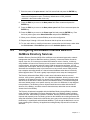
Safety Information
When using your equipment, the following safety precautions should always be
followed.
Safety During Operation
In this manual, the following important symbols are used:
R WARNING:
Indicates a potentially hazardous situation which, if instructions
are not followed, could result in death or serious injury.
R CAUTION:
Indicates a potentially hazardous situation which, if instructions are not
followed, may result in minor or moderate injury or damage to property.
ii
R WARNING:
• Connect the power cord directly into a wall outlet and never use an extension cord.
• Disconnect the power plug (by pulling the plug, not the cable) if the
power cable or plug becomes frayed or otherwise damaged.
• To avoid hazardous electric shock or laser radiation exposure, do not
remove any covers or screws other than those specified in this manual.
• Turn off the power and disconnect the power plug (by pulling the plug,
not the cable) if any of the following conditions exists:
• You spill something into the equipment.
• You suspect that your equipment needs service or repair.
• Your equipment's cover has been damaged.
• Do not incinerate spilled toner or used toner. Toner dust might ignite
when exposed to an open flame.
• Disposal can take place at our authorized dealer or at appropriate collection sites.
• If you dispose of the used toner containers yourself, dispose of them
according to your local regulations.
iii
R CAUTION:
• Protect the equipment from dampness or wet weather, such as rain, snow,
and so on.
• Unplug the power cord from the wall outlet before you move the equipment.
While moving the equipment, you should take care that the power cord will
not be damaged under the equipment.
• When you disconnect the power plug from the wall outlet, always pull the
plug (not the cable).
• Do not allow paper clips, staples, or other small metallic objects to fall inside
the equipment.
• Do not eat or swallow toner.
• Keep toner (used or unused) and toner cartridge out of reach of children.
• For environmental reasons, do not dispose of the equipment or expended
supply's wastes at a household waste a collection point. Disposal can take
place at our authorized dealer or at an appropriate collection site.
• Our products are engineered to meet the highest standards of quality and
functionality. When purchasing expendable supplies, we recommend using
only those specified by an authorized dealer.
• The inside of the machine could be very hot. Do not touch the parts with a
label indicating the “hot surface”. Otherwise, it could cause a personal burn.
iv
ENERGY STAR Program
As an ENERGY STAR Partner, we have determined that this machine model meets the ENERGY STAR Guidelines for energy efficiency.
The ENERGY STAR Guidelines intend to establish an international energy-saving system for developing and introducing energy-efficient office equipment to deal with environmental issues, such as global warming.
When a product meets the ENERGY STAR Guidelines for energy efficiency, the Partner shall place the ENERGY STAR logo onto the machine model.
This product was designed to reduce the environmental impact associated with office
equipment by means of energy-saving features, such as Low-power mode.
The ENERGY STAR Guidelines intend to establish an international energy-saving system for developing and introducing energy-efficient office equipment to deal with environmental issues, such as global warming.
This product was designed to reduce the environmental impact associated with office
equipment by means of energy-saving features, such as Low-power mode.
❖ Low-power mode (Energy Saver mode)
This printer automatically lowers its power consumption 30 minutes after
the last operation has been completed. To exit Low-power (Energy Saver)
mode, press any key on the operation panel. To change the setting of the Energy Saver mode, see P.125 “Making Printer Settings with the Operation Panel”.
❖ Specifications
Lower-power mode
(Energy Saver mode)
Type 2 Printer
*1
*1
Power Consumption
30 W or less
Default Time
30 minutes
Recovery Time
*1
Type 1 Printer
39 seconds or
less
39 seconds or
less
Please refer to the inside of the front cover of this manual to confirm which printer
(Type 1 Printer or Type 2 Printer) you have.
v
-Recycled Paper
Please contact your sales or service representative for recommended recycled
paper types that may be used in this machine.
vi
Manuals for Your Printer
Manuals for Your Printer
There are two manuals that describe the procedures separately for the installation of your printer and for the operation and maintenance of your printer and
its optional equipment.
To enhance safe and efficient operation of your printer, all users should read and
follow the instructions contained in the following manuals.
❖ Quick Installation Guide
Describes the procedures for installing your printer.
❖ Operating Instructions
Describes the procedures and necessary information on setting up and using
your printer and its optional equipment. (This Manual)
vii
How to Read this Manual
Symbols
In this manual, the following symbols are used:
R WARNING:
This symbol indicates a potentially hazardous situation which, if instructions
are not followed, could result in death or serious injury.
R CAUTION:
This symbol indicates a potentially hazardous situation which, if instructions
are not followed, may result in minor or moderate injury or damage to property.
* The statements above are notes for your safety.
Important
If this instruction is not followed, paper might be misfed, originals might be
damaged, or data might be lost. Be sure to read this.
Preparation
This symbol indicates the prior knowledge or preparations required before operating.
Note
This symbol indicates precautions for operation, or actions to take after misoperation.
Limitation
This symbol indicates numerical limits, functions that cannot be used together,
or conditions in which a particular function cannot be used.
Reference
This symbol indicates a reference.
[
]
Keys that appear on the machine's panel display.
Keys and buttons that appear on the computer's display.
{}
Keys built into the machine's operation panel.
Keys on the computer's keyboard.
viii
TABLE OF CONTENTS
1. Getting Acquainted
Features of Your Printer ...........................................................................
Guide to the Printer ...................................................................................
Type 1 Printer................................................................................................
Type 2 Printer................................................................................................
Operation Panel ............................................................................................
1
2
2
5
7
2. Installing Options
Available Options ....................................................................................
Type 1 Printer: Installing Options ..........................................................
Type 1 Printer: Installing the Paper Feed Unit (DLT) Type 2000 ................
Type 1 Printer: Installing the Paper Feed Unit (LT) Type 2000...................
Type 1 Printer: Installing the Envelope Feeder Type 2000 .........................
Type 1 Printer: Installing the Network Interface Board Type 2000..............
Type 1 Printer: Installing the Memory Unit (SIMM) .....................................
Type 2 Printer: Installing Options ..........................................................
Type 2 Printer: Installing the Paper Feed Unit Type 1400 ..........................
Type 2 Printer: Installing the Envelope Feeder Type 1400 .........................
Type 2 Printer: Installing the Network Interface Board Type 2000..............
Type 2 Printer: Installing the Memory Unit (SIMM) .....................................
12
14
14
15
16
16
18
20
20
21
22
23
3. Configuring the Printer for the Network with the Operation Panel
Setting Up the IP Parameters ................................................................. 26
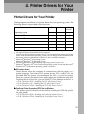
4. Printer Drivers for Your Printer
Printer Drivers for Your Printer .............................................................. 29
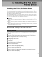
5. Installing the PCL 6/5e Printer Driver
Installing the PCL 6/5e Printer Driver ....................................................
Windows 95/98 - Installing the PCL 6/5e Printer Driver ..............................
Windows 3.1x - Installing the PCL 6/5e Printer Driver ................................
Windows NT4.0 - Installing the PCL 6/5e Printer Driver .............................
Uninstalling the PCL 6/5e Printer Driver ...............................................
Windows 95/98 - Uninstalling the PCL 6/5e Printer Driver..........................
Windows 3.1x - Uninstalling the PCL 6/5e Printer Driver............................
Windows NT4.0 - Uninstalling the PCL 6/5e Printer Driver.........................
31
31
32
34
36
36
36
37
ix
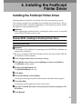
6. Installing the PostScript Printer Driver
Installing the PostScript Printer Driver .................................................
Windows 95/98 - Installing the PostScript Printer Driver.............................
Windows NT4.0 - Installing the PostScript Printer Driver............................
Macintosh - Installing the PPD File .............................................................
Uninstalling the PostScript Printer Driver.............................................
Windows 95/98 - Uninstalling the PostScript Printer Driver ........................
Windows NT4.0 - Uninstalling the PostScript Printer Driver .......................
39
39
41
44
47
47
47
7. Installing the Font Manager
Installing the Font Manager....................................................................
Windows 95/98 - Installing the Font Manager.............................................
Windows 3.1x - Installing the Font Manager ...............................................
Windows NT4.0 - Installing the Font Manager ............................................
Uninstalling the Font Manager ...............................................................
Windows 95/98 - Uninstalling the Font Manager ........................................
Windows 3.1x - Uninstalling the Font Manager...........................................
Windows NT4.0 - Uninstalling the Font Manager........................................
49
49
49
50
51
51
51
51
8. Printing a Document
PCL 6/5e - Accessing the Printer Properties ........................................
Windows 95/98 - Accessing the Printer Properties .....................................
Windows 3.1x - Accessing the Printer Setting Dialog .................................
Windows NT4.0 - Accessing the Printer Properties ....................................
PostScript - Setting Up for Printing .......................................................
Windows 95/98 - Accessing the Printer Properties .....................................
Windows NT4.0 - Accessing the Printer Properties ....................................
Macintosh - Setting Up for Printing .............................................................
Canceling a Print Job..............................................................................
Windows 95/98 - Canceling Print Job ........................................................
Windows 3.1x - Canceling a Print Job ........................................................
Windows NT4.0 - Canceling a Print Job .....................................................
53
53
54
55
57
57
58
59
61
61
61
62
9. Paper and Other Media
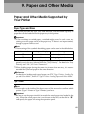
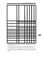
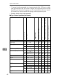
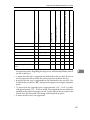
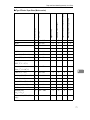
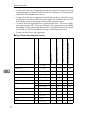
Paper and Other Media Supported by Your Printer .............................
Paper Types and Sizes ...............................................................................
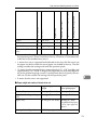
Precautions for Paper .................................................................................
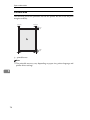
Printable Area .............................................................................................
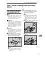
Type 1 Printer: Loading Paper and Other Media ..................................
Type 1 Printer: Loading Paper in the Standard Paper Tray ........................
Type 1 Printer: Loading Paper in the Bypass Tray .....................................
Type 1 Printer: Loading Paper in the Optional Paper Tray .........................
Type 1 Printer: Loading Envelopes .............................................................
x
65
65
74
78
79
79
81
82
84
Type 2 Printer: Loading Paper and Other Media ..................................
Type 2 Printer: Loading Paper in the Standard Paper Tray ........................
Type 2 Printer: Loading Paper in the Bypass Tray .....................................
Type 2 Printer: Loading Paper in the Optional Paper Tray .........................
Type 2 Printer: Loading Envelopes .............................................................
88
88
89
90
92
10.Troubleshooting
Error & Status Messages on the Operation Panel................................ 97
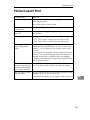
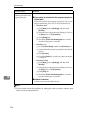
Printer Doesn't Print.............................................................................. 105
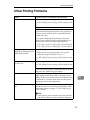
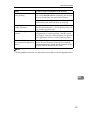
Other Printing Problems ....................................................................... 107
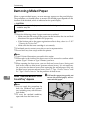
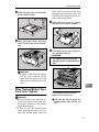
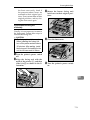
Removing Misfed Paper........................................................................ 110
When “Remove Misfeed: Front Cover&Tray” Appears ............................. 110
When “Remove Misfeed: Open Front Cover” Appears ............................. 111
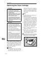
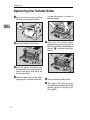
Replacing the Toner Cartridge ............................................................. 114
Cleaning the Printer .............................................................................. 117
Cleaning the Friction Pad .......................................................................... 117
Cleaning the Paper Feed Roller................................................................ 118
Cleaning the Registration Roller (Type 1 Printer only) .............................. 122
11.Making Printer Settings with the Operation Panel
Menu Chart.............................................................................................
Accessing the Main Menu.....................................................................
Making Printer Settings with the Operation Panel .............................
Job Control Menu ..................................................................................
Job Control Parameters ............................................................................
Host Interface Menu ..............................................................................
Host Interface Parameters .......................................................................
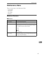
Maintenance Menu ................................................................................
Maintenance Parameters .........................................................................
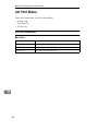
List Print Menu.......................................................................................
List Print Parameters.................................................................................
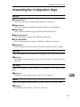
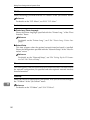
Interpreting the Configuration Page ....................................................
125
126
127
128
128
136
136
137
137
138
138
139
12.Appendix
Memory Capacity and Paper Size ........................................................
Moving and Transporting the Printer ..................................................
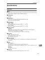
Specifications ........................................................................................
Mainframe .................................................................................................
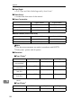
Options......................................................................................................
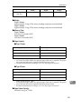
Consumables .........................................................................................
141
142
143
143
146
149
xi
INDEX...................................................................................................... 150
xii
1. Getting Acquainted
Features of Your Printer
Your printer is designed especially for office work groups, both for shared usage
within network environment, and for one-to-one usage by being connected directly to your computer.
❖ Time Saving
Superior features save time you spend on your print tasks.
• Fast Print Speed *1 : 20 ppm (Type 1 printer) and 14 ppm (Type 2 printer)
*1
A4, 81/2" × 11", maximum printing speed from a standard paper tray.
• All Front Operation: From the front side, you can replace the toner cartridge, check indicators, and clear a paper misfeed if it occurs.
❖ Compact Body
Its compact body requires minimum space to place it on your desk or desk
side.
❖ Network Connectivity
Your printer is network ready with the optional Network Interface Board
Type 2000.
❖ Major Specifications
Printing Speed
Type 1 Printer *1
Type 2 Printer *1
20 pages per minute *2
14 pages per minute *3
Maximum Print Quality
True 1200 × 1200dpi resolutions (PCL 6, PS)
Emulations
PCL 5e, PCL 6, PostScript® Level 2
Paper Tray and Bypass
Tray:
Paper Tray: A4K, 81/2" ×
11" (Letter)K
A3, 11" × 17"
Bypass Tray: A4K, 81/2" ×
14" (Legal)K
Standard Memory Size
8MB
4MB
Maximum Memory Size
with Optional Memory
40MB
36MB
Maximum Input Paper Size
*1
*2
*3
Please refer to the inside of the front cover of this manual to confirm which printer
(Type 1 Printer or Type 2 Printer) you have.
A4L, 81/2" × 11"L
A4K, 81/2" × 11"K
1
Getting Acquainted
Guide to the Printer
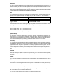
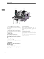
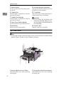
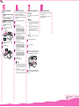
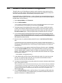
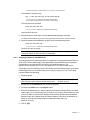
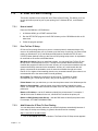
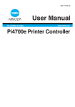
Type 1 Printer
1
Type 1 Printer: Exterior
Note
❒ Please refer to the inside of the front cover of this manual to confirm which
printer (Type 1 Printer or Type 2 Printer) you have.
3
4
5
6
8
7
8
1
2
11
9
10
12
13
14
TS3H030E
2
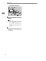
1. Bypass tray
2. Bypass Tray Extender
Use to print onto thick paper, OHP transparencies, adhesive labels, custom size
paper, and envelopes as well as plain paper. When printing on custom paper size,
printer driver's settings are required.
Up to 100 sheets of plain paper (80 g/m 2,
20 lb) can be loaded.
⇒ P.65 “Paper and Other Media Supported
by Your Printer”
⇒ P.81 “Type 1 Printer: Loading Paper in
the Bypass Tray”
Pull out this extender to load paper into
the bypass tray when its length is longer
than A4L or 81/2” x 11”L.
3. Operation Panel
Contains keys for printer operation and a
panel display that shows the printer status.
4. Power Switch
Use this switch to turn the printer power
on and off.
Guide to the Printer
5. Output Tray Extender
10. Paper Size Dial
Pull out this extender when printing on
long paper.
Adjust this dial to match the size and feed
direction of the paper loaded in the paper
tray.
6. Output Tray
Printed output is stacked here with the
print side face down.
11. Back Plates
7. Ventilator
12. Parallel Interface Connector
These holes help to keep components inside the printer from overheating.
Plug into the interface cable that connects
the printer to your computer.
Important
❒ Do not leave the ventilator obstructed or blocked. Doing so creates the danger of malfunction due
to overheating.
8. Front Cover Release Buttons
Use these buttons to open the front cover.
9. Paper Tray
Loads up to 250 sheets of plain paper (80
g/m2, 20 lb) into this tray for printing.
⇒ P.65 “Paper and Other Media Supported
by Your Printer”
1
Remove to install some options.
13. Ventilators
These holes help to keep components inside the printer from overheating.
Important
❒ Do not leave the ventilators obstructed or blocked. Doing so creates the danger of malfunction due
to overheating.
14. Power Cord
Plug this cord into a wall outlet.
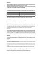
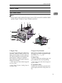
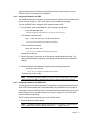
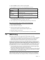
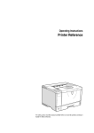
Type 1 Printer: Interior
Note
❒ Please refer to the inside of the front cover of this manual to confirm which
printer (Type 1 Printer or Type 2 Printer) you have.
3
Getting Acquainted
1 2
2 1
1
3
4
5
6
7
8
1. Pressure Release Levers (blue)
7. Transfer Roller
Push down these levers when removing
misfed paper.
When “Replace Maintenance Kit” appears on the panel display, replace this
roller.
2. Fusing Unit Lock Levers (brown)
Push down these levers when replacing
the fusing unit.
3. Fusing Unit
Fuses the image onto the paper.
When “Replace Maintenance Kit” appears on the panel display, replace this
unit.
4. Toner Cartridge
Includes toner and a photoconductor
unit.
5. Front Cover
Open this cover when accessing the inside of the printer.
6. Transfer Roller Cover
Open this cover when replacing the
transfer roller.
4
8. Registration Roller
Feeds the paper. If it becomes dirty, clean
it.
⇒ P.122 “Cleaning the Registration Roller
(Type 1 Printer only)”
Guide to the Printer
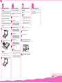
Type 2 Printer
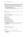
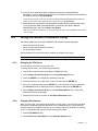
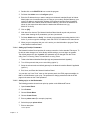
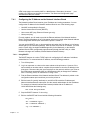
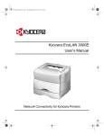
Type 2 Printer: Exterior
1
Note
Please
refer to the inside of the front cover of this manual to confirm which
❒
printer (Type 1 Printer or Type 2 Printer) you have.
4
5
6 7
8
8
1
2
9
3
11
10
12
TS4H031E
1. Bypass Tray
2. Bypass Tray Extender
Use to print onto thick paper, OHP transparencies, adhesive labels, custom size
paper, and envelopes as well as plain paper. When printing on custom paper size,
printer driver's settings are required.
Up to 100 sheets of plain paper (80 g/m 2,
20 lb) can be loaded.
⇒ P.65 “Paper and Other Media Supported
by Your Printer”
⇒ P.89 “Type 2 Printer: Loading Paper in
the Bypass Tray”
Pull out this extender to load paper into
the bypass tray when its length is longer
than B5Kor 51/2” x 1/2”K.
3. Paper Tray
Loads up to 250 sheets of plain paper ( 80
g/m2, 20 lb) into this tray for printing.
⇒ P.65 “Paper and Other Media Supported
by Your Printer”
4. Operation Panel
Contains keys for printer operation and a
panel display that shows the printer status.
5
Getting Acquainted
1
5. Power Switch
10. Parallel Interface Connector
Use this switch to turn the printer power
on and off.
Plug into the interface cable that connects
the printer to your computer.
6. Output Tray
11. Ventilators
Printed output is stacked here with the
print side face down.
These holes help to keep components inside the printer from overheating.
7. Output Tray Extender
Use these buttons to open the front cover.
Important
❒ Do not leave the ventilators obstructed or blocked. Doing so creates the danger of malfunction due
to overheating.
9. Back Plates
12. Power Cord
Printed output is stacked here with the
print side face down.
8. Front Cover Release Buttons
Plug this cord into a wall outlet.
Remove to install some options.
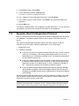
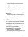
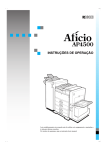
Type 2 Printer: Interior
Note
❒ Please refer to the inside of the front cover of this manual to confirm which
printer (Type 1 Printer or Type 2 Printer) you have.
1 2
21
3
4
5
6
7
8
TS4H050J
6
1. Pressure Release Levers (blue)
2. Fusing Unit Lock Levers (brown)
Push down these levers when removing
misfed paper.
Push down these levers when replacing
the fusing unit.
Guide to the Printer
3. Fusing Unit
5. Toner Cartridge
Fuses the image onto the paper.
When ”Replace Maintenance Kit” appears on the panel display, replace this
unit.
Includes toner and a photoconductor
unit.
6. Front Cover
1
Open this cover when accessing the inside of the printer.
4. Ventilator
This hole helps to keep components inside the printer from overheating.
7. Transfer Roller Cover
Open this cover when replacing the
transfer roller.
Important
❒ Do not leave the ventilator obstructed or blocked. Doing so creates the danger of malfunction due
to overheating of components inside the printer.
8. Transfer Roller
When ”Replace Maintenance Kit” appears on the panel display, replace this
roller.
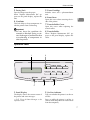
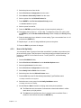
Operation Panel
2
1
On Line Job Reset Escape
Form Feed
Power
3
Menu
Error
Data In
4
5
Enter
TS3S010E
1. Panel Display
2. On Line indicator
The display shows the current status of
the printer and error messages.
⇒ P.97 “Error & Status Messages on the
Operation Panel”
Tells you whether the printer is on-line or
off-line.
Stays on while the printer is on-line (a
state in which the printer can receive data
from the computer).
7
Getting Acquainted
Stays off when the printer is off-line (a
state in which printer can not receive data).
3. Power indicator
1
Stays on while the printer power is on.
Stays off when the power is turned off or
while the printer is in the Energy Saver
save mode.
4. Error indicator
Blinks or lights up whenever any printer
error occurs. A message describing the
cause of the error also appears on the
panel display.
⇒ P.97 “Error & Status Messages on the
Operation Panel”
5. Data In indicator
Blinks while the printer is receiving data
from a computer.
Stays on if there is data to be printed.
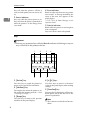
Keys
Important
❒ Pressing any operation key while the Data In indicator is blinking or stays on
may cause data in the printer to be lost.
1
2
On Line Job Reset
Form Feed
Menu
3
4
Escape
Enter
TS3S020E
5
6
1. {On Line} key
4. {U}{T} keys
Press this key to switch the printer between on-line and off-line conditions.
Use these keys to increase or decrease
values on the panel display when making
settings.
2. {Job Reset} key
Pressing this key when the printer is online cancels the ongoing print job. ⇒ P.61
“Canceling a Print Job”
3. {Escape} key
Press this key to return to the previous
condition on the panel display.
8
7
5. {Form Feed} key
Pressing this key during the off-line condition prints out all the data left in the
printer's input buffer.
Note
❒ This is doesn't work in the on-line condition.
Guide to the Printer
6. {Menu} key
Press this key to make and check the current printer settings. ⇒ P.125 “Making
Printer Settings with the Operation Panel”
1
7. {Enter} key
Press this key to execute menu items selected on the panel display.
Press this key to clear some errors.⇒ P.97
“Troubleshooting”
9
Getting Acquainted
1
10
2. Installing Options
R CAUTION:
• Make sure to turn off the printer and wait for about 30 minutes before install-
ing options. Not waiting for the printer to cool down can result in a burn.
• When lifting the machine, use the inset grips on both sides of the machine.
Otherwise, the machine might fall and cause personal injury.
• When you move the machine, unplug the power cord from the wall outlet to
avoid a fire or an electric shock.
❖ Option List
Note
❒ Please refer to the inside of the front cover of this manual to confirm which
printer (Type 1 Printer or Type 2 Printer) you have.
Type 1 Printer
Paper Feed Unit (DLT) Type 2000 *1
❍
Paper Feed Unit (LT) Type 2000 *1
❍
❍
Paper Feed Unit Type 1400 *2
Envelope Feeder Type 2000 *3
Type 2 Printer
❍
❍
Envelope Feeder Type 1400 *4
Network Interface Board Type 2000
❍
❍
Memory Unit Type 204 (16MB)
❍
❍
Memory Unit Type 204 (32MB)
❍
❍
❍ : This option can be installed.
*1
*2
*3
*4
Type 1 Printer: You can install any combination of these units. Up to two paper
feed unit can be installed to your printer at a time.
Type 2 Printer: Only one paper feed unit can be installed at a time.
This requires the installation of the Paper Feed Unit Type 2000.
This requires the installation of the Paper Feed Unit Type 1400.
11
Installing Options
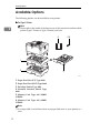
Available Options
The following options can be installed to your printer.
❖ For Type 1 Printer
Note
❒ Please refer to the inside of the front cover of this manual to confirm which
printer (Type 1 Printer or Type 2 Printer) you have.
2
4
5,6
1
2
3
TS3P100E
1. Paper Feed Unit (LT) Type 2000
2. Paper Feed Unit (DLT) Type 2000
3. Envelope Feeder Type 2000
4. Network Interface Board Type
2000
5. Memory Unit Type 204 (16MB)
(SIMM)
6. Memory Unit Type 204 (32MB)
(SIMM)
Note
❒ It is impossible to install more than two paper feed units to your printer at a
time.
12
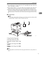
Available Options
❒ Any combination of Paper Feed Unit (LT) Type 2000 and Paper Feed Unit
(DLT) Type 2000 is available.
❒ The envelope feeder is a tray that slides into the optional paper feed unit.
Without the optional paper feed unit, the envelope feeder cannot be used.
❒ The Type 1 Printer can have two optional paper feed units installed at a time.
However the envelope feeder should be used in the top-most optional paper
feed unit (tray 2). It cannot be used in the bottom-most paper feed unit (tray
3).
2
❖ For Type 2 Printer
Note
❒ Please refer to the inside of the front cover of this manual to confirm which
printer (Type 1 Printer or Type 2 Printer) you have.
3
4,5
1
2
TS4P100E
1. Paper Feed Unit Type 1400
2. Envelope Feeder Type 1400
3. Network Interface Board Type
2000
4. Memory Unit Type 204 (16MB)
(SIMM)
5. Memory Unit Type 204 (32MB)
(SIMM)
Note
❒ It is impossible to install more than one paper feed unit to your printer at a
time.
13
Installing Options
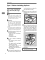
Type 1 Printer: Installing Options
Type 1 Printer: Installing the
Paper Feed Unit (DLT) Type
2000
2
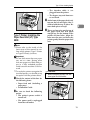
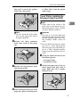
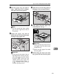
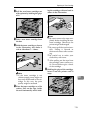
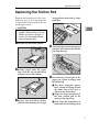
used to hold the tray in place. Remove both pieces of tape.
D Attach the tray cover to the top of
the paper tray as shown in the illustration.
Note
❒ Please refer to the inside of the
front cover of this manual to confirm which printer (Type 1 Printer
or Type 2 Printer) you have.
Important
❒ Do not slide more than one paper
tray out at a time. Having more
than one paper tray filled with paper in a fully extended position
could cause the machine to tilt forward.
❒ To make the printer recognize the
installed option, you should set up
the option with the printer driver.
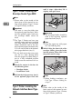
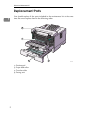
A Check the contents of the box for
TS3P070E
E There are four pins on the top of
the paper feed unit that point
straight up. On the bottom of the
printer are four holes. Align the
holes over the pins and lower the
printer gently onto the paper feed
unit.
the following items.
• Paper feed unit (including a
paper tray)
• Tray cover
• Installation Guide
B Be
sure to check the following
points:
• The printer's power switch is
turned off.
• The power cord is unplugged
from the wall outlet.
• The interface cable is unplugged from the printer.
• The bypass tray and front cover are closed.
C At the front of the paper feed unit,
tape on the left and right sides is
14
TS3P061E
R CAUTION:
• When lifting the printer, use the
inset grips on both sides.
Type 1 Printer: Installing Options
• The interface cable is unplugged from the printer.
• The bypass tray and front cover are closed.
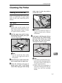
C At the front of the paper feed unit,
tape on the left and right sides is
used to hold the tray in place. Remove both pieces of tape.
TS3K010E
Type 1 Printer: Installing the
Paper Feed Unit (LT) Type
2000
2
D There are four pins on the top of
the paper feed unit that point
straight up. On the bottom of the
printer are four holes. Align the
holes over the pins and lower the
printer gently onto the paper feed
unit.
Note
❒ Please refer to the inside of the
front cover of this manual to confirm which printer (Type 1 Printer
or Type 2 Printer) you have.
Important
❒ Do not slide more than one paper
tray out at a time. Having more
than one paper tray filled with paper in a fully extended position
could cause the machine to tilt forward.
❒ To make the printer recognize the
installed option, you should set up
the option with the printer driver.
A Check the content of the box for
TS3P062E
R CAUTION:
• When lifting the printer, use the
inset grips on both sides.
the following items.
• Paper feed unit (including a
paper tray)
• Installation Guide
B Be
sure to check the following
points:
• The printer's power switch is
turned off.
• The power cord is unplugged
from the wall outlet.
TS3K010E
15
Installing Options
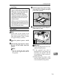
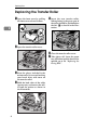
Type 1 Printer: Installing the
Envelope Feeder Type 2000
until it stops. After that, lift it
slightly, then pull it out.
Note
❒ Please refer to the inside of the
front cover of this manual to confirm which printer (Type 1 Printer
or Type 2 Printer) you have.
2
Important
❒ This unit is a tray that slides into
the optional paper feed unit. Without the optional paper feed unit,
this envelope feeder cannot be
used.
❒ The Type 1 Printer can have two
optional paper feed units installed
at a time. However, the envelope
feeder should be used in the topmost optional paper feed unit (tray
2). It can not be used in the bottommost paper feed unit (tray 3).
❒ Do not slide more than one paper
tray out at a time. Having more
than one paper tray filled with paper in a fully extended position
could cause the machine to tilt toward.
TS3Y150E
Important
❒ The envelope feeder should be
used in the top-most optional
paper feed unit (tray 2).
Note
❒ Keep the paper tray with paper
in a cool and dry place.
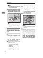
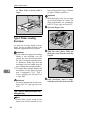
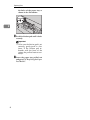
C While lifting the front side of the
envelope feeder, place the feeder
into the printer. Then slide it into
the printer until it stops.
A Check the content in the box for
the following items.
• Envelope feeder
• Installation Guide
B Pull out the 2nd paper tray (tray 2)
of the optional paper feed unit
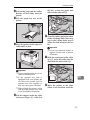
Type 1 Printer: Installing the
Network Interface Board Type
2000
16
TS3Y290E
Note
❒ When loading envelopes, see
P.84 “Type 1 Printer: Loading Envelopes”.
Note
❒ Please refer to the inside of the
front cover of this manual to confirm which printer (Type 1 Printer
or Type 2 Printer) you have.
Type 1 Printer: Installing Options
❒ Use the shielded twisted-pair
(STP) network interface cable.
❒ The network interface board can
be attached to either the left or the
right side of the back of your printer. This procedure is for attaching
to the left side.
❒ You cannot install two network interface boards at a time.
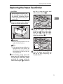
used to be. Make sure that the
board is aligned so that the jack is
facing out and is on the bottom.
Press the board firmly against the
printer. The interface connectors
on the printer and the board
should align and offer a slight resistance before popping into
place.
2
A Check the contents of the box for
the following items.
• Network interface board
• CD-ROM
• Ferrite Core
• Installation Guide
• Quick Configuration Guide
• Additional Documentation
B Be
sure to check the following
points:
• The printer's power switch is
turned off.
• The power cord is unplugged
from the wall outlet.
TS3P090E
Note
❒ Use a coin to reattach the
screws.
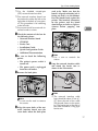
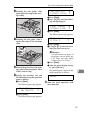
E Loop the network interface cable
and attach the ferrite core as
shown in the illustration.
C Remove the back plate.
1
TS3P110E
TS3P080E
Note
❒ A coin can be used to remove
the screws.
D Align the screw holes of the network interface board over the
screw holes where the back plate
Note
❒ The network interface cable
loop should be about 15 cm (6")
(A) from the end of the cable
(on the end closest to the printer). The ferrite core at the end of
the cable should be a ring type
ferrite core.
17
Installing Options
F Attach the network interface cable to the jack on the board as
shown in the illustration.
2
TS3C041E
G Connect the other end of the network interface cable to the network.
H Plug
the printer's power cord
back into the wall outlet and turn
on the printer's power switch.
The configuration page of the network interface board will be printed automatically. Check the
configuration of the network interface board with it.
Important
❒ After installing the network interface board properly, set up
the printer's network environment using the operation panel.
See P.25 “Configuring the Printer
for the Network with the Operation
Panel”.
Type 1 Printer: Installing the
Memory Unit (SIMM)
Note
❒ Please refer to the inside of the
front cover of this manual to confirm which printer (Type 1 Printer
or Type 2 Printer) you have.
18
Important
❒ The memory unit can be damaged
by small amount of static electricity. Before touching it, touch something metal to remove static
electricity from you.
❒ To make the printer recognize the
installed option, you should set up
the option with the printer driver.
❒ This printer has one slot for a
SIMM, and you can install one
SIMM at a time.
A Be
sure to check the following
points:
• The printer's power switch is
turned off.
• The power cord is unplugged
from the wall outlet.
B Remove the back plate.
TS3P030E
Note
❒ A coin can be used to remove
the screws.
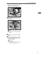
C Make sure that the notch of the
memory unit should be upward
as shown in the illustration. Tilt
the memory unit to the left so that
it is in 45 degrees from perpendicular to the slot, and slide it into
the slot (A). Tilt the memory unit
so that it is perpendicular to the
Type 1 Printer: Installing Options
slot (B). It should make an audible click as it pops into place.
1
2
2
TS3S040E
D Attach the back plate to its original position.
TS3P050E
Note
❒ A coin can be used to attach the
screws.
E Turn
on the printer's power
switch.
F Print a configuration test sheet to
confirm that the memory unit is
properly installed.
Reference
⇒ P.125 “Making Printer Settings
with the Operation Panel”
19
Installing Options
Type 2 Printer: Installing Options
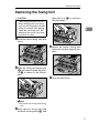
Type 2 Printer: Installing the
Paper Feed Unit Type 1400
2
Note
❒ Please refer to the inside of the
front cover of this manual to confirm which printer (Type 1 Printer
or Type 2 Printer) you have.
D There are four pins on the top of
the paper feed unit that point
straight up. On the bottom of the
printer are four holes. Align the
holes over the pins and lower the
printer gently onto the paper feed
unit.
Important
❒ Do not slide more than one paper
tray out at a time. Having more
than one paper tray filled with paper in a fully extended position
could cause the machine to tilt forward.
❒ To make the printer recognize the
installed option, you should set up
the option with the printer driver.
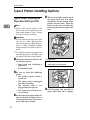
A Check the contents of the box for
the following items.
• Paper feed unit (including a
paper tray)
• Installation Guide
TS4P121E
R CAUTION:
• When lifting the printer, use the
inset grips on both sides.
B Be
sure to check the following
points:
• The printer's power switch is
turned off.
• The power cord is unplugged
from the wall outlet.
• The interface cable is unplugged from the printer.
• The bypass tray and front cover are closed.
C At the front of the paper feed unit,
tape on the left and right sides is
used to hold the tray in place. Remove both pieces of tape.
20
TS4K010E
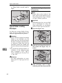
E Pull
the paper tray out until it
stops. After then, lift it slightly,
Type 2 Printer: Installing Options
then pull it out of the printer.
Place it on a flat surface.
er. Then slide it into the printer
until it stops.
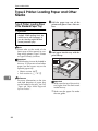
Type 2 Printer: Installing the
Envelope Feeder Type 1400
TS4Y091E
Note
❒ Do not touch the three white
pins on the right front side of
the paper feed unit.
F Remove
the white protective
sheet from inside of the paper
tray.
Note
❒ Please refer to the inside of the
front cover of this manual to confirm which printer (Type 1 Printer
or Type 2 Printer) you have.
2
Important
❒ This unit is a tray that slides into
the optional paper feed unit. Without the optional paper feed unit,
this envelope feeder cannot be
used.
❒ Do not slide more than one paper
tray out at a time. Having more
than one paper tray filled with paper in a fully extended position
could cause the machine to tilt toward.
A Check the content of the box for
TS4Y111E
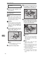
G Remove the red protective sheet
taped on the guide.
the following items.
• Envelope feeder
• Installation Guide
B Pull out the paper tray of the op-
tional paper feed unit until it
stops. After that, lift it sightly,
then pull it out.
TS4Y301E
H While lifting the front side of the
TS4Y150E
paper tray, place it into the print-
21
Installing Options
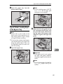
Note
❒ Keep the paper tray with paper
in a cool and dry place.
C While lifting the front side of the
envelope feeder, place the feeder
into the printer. Then slide it into
the printer until it stops.
2
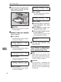
• Additional Documentation
B Be
sure to check the following
points:
• The printer's power switch is
turned off.
• The power cord is unplugged
from the wall outlet.
C Remove the back plate.
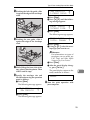
TS4Y290E
Note
❒ When loading envelopes, see
P.92 “Type 2 Printer: Loading Envelopes”.
Type 2 Printer: Installing the
Network Interface Board Type
2000
Note
❒ Please refer to the inside of the
front cover of this manual to confirm which printer (Type 1 Printer
or Type 2 Printer) you have.
❒ Use the shielded twisted-pair
(STP) network interface cable.
A Check the contents in the box for
the following items.
• Network interface board
• CD-ROM
• Ferrite Core
• Installation Guide
• Quick Configuration Guide
22
TS4P030E
Note
❒ A coin can be used to remove
the screws.
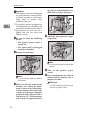
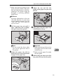
D Align the screw holes of the net-
work interface board over the
screw holes where the back plate
used to be. Make sure that the
board is aligned so that the jack is
facing out and is on the bottom.
Press the board firmly against the
printer. The interface connectors
on the printer and the board
should align and offer a slight re-
Type 2 Printer: Installing Options
sistance
place.
before
popping
into
F Attach the network interface cable to the jack on the board as
shown in the illustration.
2
TS4P090E
TS4C041E
Note
❒ Use a coin to reattach the screws
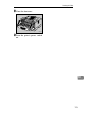
E Loop the network interface cable
and attach the ferrite core as
shown in the illustration.
G Connect the other end of the net-
work interface cable to the network.
H Plug
the printer's power cord
back into the wall outlet and turn
on the printer's power switch.
The configuration page of the network interface board will be printed automatically. Check the
configuration of the network interface board with it.
1
TS3P110E
Note
❒ The network interface cable
loop should be about 15 cm (6")
(A) from the end of the cable
(on the end closest the printer).
The ferrite core at the end of the
cable should be a ring type ferrite core.
Important
After
installing the network in❒
terface board properly, set up
the printer's network environment using the operation panel.
See P.25 “Configuring the Printer
for the Network with the Operation
Panel”.
Type 2 Printer: Installing the
Memory Unit (SIMM)
Note
❒ Please refer to the inside of the
front cover of this manual to confirm which printer (Type 1 Printer
or Type 2 Printer) you have.
23
Installing Options
Important
❒ The memory unit can be damaged
by small amount of static electricity. Before touching it, touch something metal to remove static
electricity from you.
❒ To make the printer recognize the
installed option, you should set up
the option with the printer driver.
❒ This printer has one slot for a
SIMM, and you can install one
SIMM at a time.
2
A Be
sure to check the following
points:
• The printer's power switch is
turned off.
• The power cord is unplugged
from the wall outlet.
the slot (B). It should make an audible click as it pops into place.
1
2
TS4P040E
D Attach the back plate to its original position.
B Remove the back plate.
TS4P050E
Note
❒ A coin can be used to attach the
screws.
E Turn
TS4P060E
Note
❒ A coin can be used to remove
the screws.
C Make sure that the notch of the
memory unit should be downward as shown in the illustration.
Tilt the memory unit to the right
so that it is in 45 degrees from perpendicular to the slot, and slide it
into the slot (A). Tilt the memory
unit so that it is perpendicular to
24
on the printer's power
switch.
F Print a configuration test sheet to
confirm that the memory unit is
properly installed.
Reference
⇒ P.125 “Making Printer Settings
with the Operation Panel”
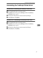
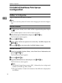
3. Configuring the Printer for
the Network with the
Operation Panel
25
Configuring the Printer for the Network with the Operation Panel
Setting Up the IP Parameters
After installing the optional network
interface board, configure it for the
network using the printer's operation
panel.
Reference
⇒ P.16 “Type 1 Printer: Installing
the Network Interface Board Type
2000”
3
⇒ P.22 “Type 2 Printer: Installing
the Network Interface Board Type
2000”
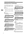
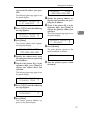
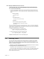
A Press {Menu}.
The following message appears on
the panel display.
Main Menu:
Job Control
j
l
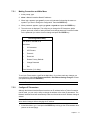
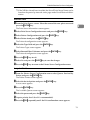
B Press {T}{U} until the following
message appears.
Main Menu:
j
Host Interfacel
C Press {Enter}.
The following message appears on
the panel display.
Host Interface:j
1.Printer Lang.l
D Press {T}{U} until the following
message appears.
Host Interface:j
1.Network Setupl
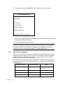
E Press {Enter}.
The following message appears on
the panel display.
Network Setup: j
1.IP Address
l
F Press {Enter}.
The current IP address appears on
the panel display. A pointer (k)
blinks on the value to be specified.
IP Address: jld#
000.000.000.000
G Specify the first (leftmost) 3 digits
of the IP address using {U} {T}.
Use {U} to increase a value, and
{T} to decrease.
IP Address: jld#
100.000.000.000
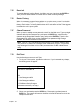
H Press {Enter}.
A pointer (k) moves to the second
3 digits.
Note
❒ Before pressing {Enter}, you can
return the pointer (k) to the previous (left) 3 digits by pressing
{Escape}.
❒ If you press {Escape} when the
pointer (k) is on the leftmost 3
digits, the specified IP address
is canceled and you can return
to the previous panel display.
I Repeat steps G and H to specify
the rest of the digits of the IP address.
J Check if the pointer (k) is at the
rightmost digit, press {Enter} to
26
Setting Up the IP Parameters
register the IP address you specified.
The following message appears on
the panel display.
Network Setup: j
1.IP Address
l
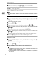
K Press {T}{U} until the following
message appears.
Network Setup: j
2.Subnet Mask l
L Press {Enter}.
The current subnet mask appears
on the panel display.
Subnet Mask:jld#
255.000.000.000
M Specify
the subnet mask using
the same procedure for specifying
the IP address.
N Check if the pointer (k) is at the
rightmost digit, press {Enter} to
register the subnet mask you
specified.
The following message appears on
the panel display.
Gateway
jld#
000.000.000.000
Q Specify the gateway address us-
ing the same procedure for specifying the IP address.
R Check if the pointer (k) is at the
rightmost digit, press {Enter} to
register the gateway address you
specified.
The following message appears on
the panel display.
3
Network Setup: j
3 .Gateway
l
S Press {On Line}.
The panel display returns to the
ready condition as follows:
Ready
T Turn the printer's power
switch
off and on.
Network Setup: j
2.Subnet Mask l
O Press {T}{U} until the following
message appears.
Network Setup: j
3.Gateway
l
P Press {Enter}.
The current gateway address appears on the panel display.
27
Configuring the Printer for the Network with the Operation Panel
3
28
4. Printer Drivers for Your
Printer
Printer Drivers for Your Printer
Printing requires installation of a printer driver for your operating system. The
following drivers are provided with this printer.
Emulation
PCL 5e
PCL 6
PostScript
Level2
Windows 95 *4
√
√
√ *1
Windows 98 *5
√
√
√ *1
Windows 3.1x *6
√
√
Windows NT4.0 *7
√
√
Operating system
Macintosh
*1
*2
*3
*4
*5
*6
*7
√ *1
√ *1
*2 *3
PPD (PostScript Printer Description) files are included in the CD-ROM.
The optional network interface board is required.
You can use the LaserWriter printer driver. Use the appropriate printer driver that
comes with the Macintosh operating system you are using. See the documentation
that comes with your Macintosh for details on the LaserWriter functions.
Microsoft® Windows® 95 operating system
Microsoft® Windows® 98 operating system
Microsoft® Windows® for Workgroups operating system Version 3.11
Microsoft® Windows NT® Server network operating system Version 4.0, Microsoft®
Windows NT® Workstation operating system Version 4.0
❖ PCL printer drivers
Printer drivers allow the computer to communicate with the printer via a
printer language. Two kinds of PCL printer drivers, PCL 6 and PCL 5e, are
provided with this printer. We recommend the PCL 6 as your first choice.
However, some of your applications might require the installation of the PCL
5e printer driver. In this case, you can install PCL 5e in addition to the PCL 6.
⇒ P.31 “Windows 95/98 - Installing the PCL 6/5e Printer Driver”
⇒ P.32 “Windows 3.1x - Installing the PCL 6/5e Printer Driver”
⇒ P.34 “Windows NT4.0 - Installing the PCL 6/5e Printer Driver”
❖ PostScript Printer Description (PPD) files for Windows
The printer specific functions can be used by installing the PPD file specific
for your printer.
⇒ P.39 “Windows 95/98 - Installing the PostScript Printer Driver”
⇒ P.41 “Windows NT4.0 - Installing the PostScript Printer Driver”
29
Printer Drivers for Your Printer
❖ PostScript Printer Description (PPD) files for Macintosh
PPD files, in combination with the LaserWriter driver, allow the computer to
communicate with the printer. The printer specific functions can be used by
installing a PPD file. You can use the LaserWriter printer driver that comes
with your Macintosh. Use the appropriate printer driver that comes with the
Macintosh operating system you are using. See the documentation that comes
with your Macintosh for details on the LaserWriter functions.
⇒ P.44 “Macintosh - Installing the PPD File”
4
30
5. Installing the PCL 6/5e
Printer Driver
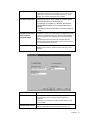
Installing the PCL 6/5e Printer Driver
This section provides basic procedures for installing the printer driver. The actual procedure differs somewhat depending on your operating system. Follow
the right one of the procedures below.
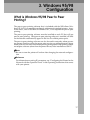
We recommend the PCL 6 as your first choice. However, some of your application software might require the installation of the PCL 5e printer driver. In this
case, you can install the PCL 5e in addition to the PCL 6.
Important
❒ When you set the print resolution to 300dpi, you should install the PCL 5e
driver.
❒ When you set the printer resolution to 1200dpi, you should install the PCL 6
driver.
❒ When updating the printer driver by installing the latest version, you should
uninstall the former version, if any.
Windows 95/98 - Installing the PCL 6/5e Printer Driver
Installing the printer driver
Follow these steps to install the PCL 6/5e printer driver on your Windows 95/
98 system:
A Insert the CD-ROM that comes with your printer in the CD-ROM drive.
B Close all applications that are currently running.
C Click [Start] on the task bar.
D Click [Run].
E In the [Run] window, click [Browse].
F Select the CD-ROM Drive.
G Open the folder called [PCL5E] or [PCL6].
H Open the folder called [WIN31_95].
I Open the folder of the appropriate language for your operating system.
J Open the folder called [DISK1].
31
Installing the PCL 6/5e Printer Driver
K Select the file titled [SETUP.EXE].
L Click [Open].
M Click [OK].
N Follow the instructions on the screen.
O If you are asked if you want to restart Windows, select [Yes]. If you are not
asked, restart Windows after completing the installation.
P Click [Start] on the task bar, point to [Settings], and then click [Printers].
The [Printers] window appears.
Q Select the icon of the printer you installed by clicking it.
R On the [File] menu, click [Properties].
S On the [General] tab, click [Print Test Page].
5
Important
❒ If your printer is equipped with certain options (ex. paper feed unit or
memory unit), you should set up the options with the printer driver.
Setting up options
A Click [Start] on the task bar, point to [Settings], and then click [Printers].
The [Printers] window appears.
B Select the icon of the printer you want to use by clicking it.
C On the [File] menu, click [Properties].
The Printer Properties appears.
D Click the [Accessories] tab.
E Set up any options you have installed on your printer.
F Click [OK].
Windows 3.1x - Installing the PCL 6/5e Printer Driver
Installing the printer driver
Follow these steps to install the PCL 6/5e printer driver on your Windows 3.1x
system:
32
Installing the PCL 6/5e Printer Driver
A Insert the CD-ROM that comes with your printer in the CD-ROM drive.
B Close all applications that are currently running.
C From the [Program Manager], select [Run] from the [File] menu.
D In the [Run] window, click [Browse…].
E Select the CD-ROM Drive in the [Drives] list.
F Open the folder called [PCL5E] or [PCL6].
G Open the folder called [WIN31_95].
H Open the folder of the appropriate language for your operating system.
I Open the folder called [DISK1].
J Select the file titled [SETUP.EXE].
K Click [OK].
L Click [OK].
M Follow the instructions on the screen.
N If you are asked if you want to restart Windows, select [Yes]. If you are not
5
asked, restart Windows after completing the installation.
Important
❒ If your printer is equipped with certain options (ex. paper feed unit or
memory unit), you should set up the options with the printer driver.
Setting up options
A From the [Main] group of the [Program Manager], open [Control Panel] by double-clicking it.
B Double-click the [Printers] icon.
C In the [Installed Printers] list box, click the name of the printer you want to
use so its name is highlighted.
D Click [Setup].
E Click the [Accessories] tab.
F Set up any options you have installed on your printer.
G Click [OK].
33
Installing the PCL 6/5e Printer Driver
H Click [Close] to close the [Printers] dialog.
Windows NT4.0 - Installing the PCL 6/5e Printer Driver
Installing the printer driver
Limitation
❒ Installing the printer driver requires full control access rights. To install the
printer driver, log on as an Administrator or a Power Users group member.
A Insert the CD-ROM that comes with your printer in the CD-ROM drive.
B Close all applications that are currently running.
C Click [Start] on the task bar.
D Click [Run].
E In the [Run] window, click [Browse].
F Select the CD-ROM Drive.
G Open the folder called [PCL5E] or [PCL6].
H Open the folder called [NT4].
I Open the folder of the appropriate language for your operating system.
J Open the folder called [DISK1].
K Select the file titled [SETUP.EXE].
L Click [Open].
M Click [OK].
N Follow the instructions on the screen.
O If you are asked if you want to restart Windows, select [Yes]. If you are not
5
asked, restart Windows after completing the installation.
P Click [Start] on the task bar, point to [Settings], and then click [Printers].
The [Printers] window appears.
Q Select the icon of the printer you installed by clicking it.
R On the [File] menu, click [Properties].
S On the [General] tab, click [Print Test Page].
34
Installing the PCL 6/5e Printer Driver
Important
❒ If your printer is equipped with certain options (ex. paper feed unit or
memory unit), you should set up the options with the printer driver.
Setting up options
A Click [Start] on the task bar, point to [Settings], and then click [Properties].
The [Printers] windows appears.
B Select the icon of the printer you want to use by clicking it.
C On the [File] menu, click [Properties].
The Printer Properties appears.
D Click the [Accessories] tab.
E Set up any options you have installed on your printer.
F Click [OK].
5
35
Installing the PCL 6/5e Printer Driver
Uninstalling the PCL 6/5e Printer Driver
This section provides basic procedures for uninstalling the printer driver. The
actual procedure differs somewhat depending on your operating system.
Follow one of the procedures below.
Windows 95/98 - Uninstalling the PCL 6/5e Printer Driver
Follow these steps to uninstall the printer driver:
A Insert the CD-ROM that comes with your printer in the CD-ROM drive.
B Close all applications that are currently running.
C Click [Start] on the task bar.
D Click [Run].
E In the [Run] window, click [Browse].
F Select the CD-ROM Drive.
G Open the folder called [PCL5E] or [PCL6].
H Open the folder called [WIN31_95].
I Open the folder of the appropriate language for your operating system.
J Open the folder called [DISK1].
K Select the file titled [UNSETUP.EXE].
L Click [Open].
M Click [OK].
N Follow the instructions on the screen.
O If you are asked if you want to restart Windows, select [Yes]. If you are not
5
asked, restart Windows after completing the uninstallation.
Windows 3.1x - Uninstalling the PCL 6/5e Printer Driver
Follow these steps to uninstall the PCL 6/5e printer driver on your Windows
3.1x system:
A Insert the CD-ROM that comes with your printer in the CD-ROM drive.
B Close all applications that are currently running.
36
Uninstalling the PCL 6/5e Printer Driver
C From the [Program Manager], select [Run] from the [File] menu.
D In the [Run] window, click [Browse…].
E Select the CD-ROM Drive in the [Drives] list.
F Open the folder called [PCL5E] or [PCL6].
G Open the folder called [WIN31_95].
H Open the folder of the appropriate language for your operating system.
I Open the folder called [DISK1].
J Select the file titled [UNSETUP.EXE].
K Click [OK].
L Click [OK].
M Follow the instructions on the screen.
N If you are asked if you want to restart Windows, select [Yes]. If you are not
5
asked, restart Windows after completing the uninstallation.
Windows NT4.0 - Uninstalling the PCL 6/5e Printer Driver
Limitation
❒ Uninstalling the printer driver requires full control access rights. To uninstall
the printer driver, log on as an Administrator or a Power Users group member.
A Insert the CD-ROM that comes with your printer in the CD-ROM drive.
B Close all applications that are currently running.
C Click [Start] on the task bar.
D Click [Run].
E In the [Run] window, click [Browse].
F Select the CD-ROM Drive.
G Open the folder called [PCL5E] or [PCL6].
H Open the folder called [NT4].
I Open the folder of the appropriate language for your operating system.
J Open the folder called [DISK1].
37
Installing the PCL 6/5e Printer Driver
K Select the file titled [UNSETUP.EXE].
L Click [Open].
M Click [OK].
N Follow the instructions on the screen.
O If you are asked if you want to restart Windows, select [Yes]. If you are not
asked, restart Windows after completing the installation.
5
38
6. Installing the PostScript
Printer Driver
Installing the PostScript Printer Driver
Printing requires installation of a printer driver for your operating system.
This section provides basic procedures for installing the printer driver. The actual procedure differs somewhat depending on your operating system. Follow
the right one of the procedures below.
Important
❒ When updating the printer driver by installing the latest version, you should
uninstall that of former version, if any.
Windows 95/98 - Installing the PostScript Printer Driver
Installing the printer driver
Important
❒ The Windows 95 or Windows 98 operating system CD-ROM or diskettes are
required for installation.
❒ Be sure to install the PPD file for Windows 95/98. Do not install the PPD file
for Windows NT4.0 accidently.
A Close all applications that are currently running.
B Click [Start] on the task bar, point to [Settings], and then click [Printers].
The [Printers] window opens.
C Double-click [Add Printers] icon.
The [Add Printer Wizard] starts up.
D Click [Next].
E Check [Local Printer], and click [Next].
A dialog for selecting the printer manufacturer and model name appears.
F Click [Have Disk].
A dialog for installing the driver from a disk opens.
G Insert the CD-ROM that comes with your printer into your computer's CDROM drive.
H Click [Browse].
39
Installing the PostScript Printer Driver
I Use the [Drives:] list box to select the CD-ROM drive.
J In the [Folders:] box, double-click [PS] and [WIN95]. Then double-click the
folder of the appropriate language for your operating system. Finally, click
[OK].
K Click [OK].
L Select the name of the printer whose driver you want to install by clicking
it, and then click [Next].
M In the [Available ports:] box, select [Printer Port] by clicking it, and then click
[Next].
N Change the name of the printer, if you want, and then click [Next].
O Specify whether or not you want to print a test page, and then click [Finish].
P If you are asked to insert the Windows 95/98 system disk, insert it into your
computer, and then click [OK].
Q If you are asked to specify the location of the required file for Windows 95/
6
98, do the following:
• Select the folder [WIN95] or [WIN98] in the system disk.
• Move to the folder where Windows is installed. Then, select the appropriate folder. The location of the appropriate folder may differ depending on
the version of your operating system. The following are examples:
[\WINDOWS\SYSTEM\OPTION\CABS]
[\WINDOWS\OPTION\CABS]
R If you are asked if you want to restart Windows, select [Yes]. If you are not
asked, restart Windows after completing the installation.
Important
❒ If your printer is equipped with certain options (ex. paper feed unit or
memory unit), you should set up the options with the printer driver.
-Using the printer driver with the Adobe PageMaker for Windows 95/
98
If you use the printer under Windows 95/98 with the Adobe PageMaker, you
need to copy the PPD file to the PageMaker directory.
The PPD file is the file with extension ".ppd" under on the directory
\PS\WIN95\ENGLISH\, on the CD-ROM that comes with your printer. The
last directory, "ENGLISH" may be substituted by appropriate language name.
Copy this file to the PageMaker's directory.
40
Installing the PostScript Printer Driver
For PageMaker 6 default installation, the directory is "C:\PM6\USENGLISH\PPD4", and for PageMaker 6.5 default installation, the directory is
"C:\PM65\RSRC\USENGLISH\PPD4". The "USENGLISH" may be different,
depending on your language selection.
Setting up options
A Click [Start] on the task bar, point to [Settings], and then click [Printers].
The [Printers] window appears.
B Select the icon of the printer you want to use by clicking it.
C On the [File] menu, click [Properties].
The Printer Properties appears.
D Click the [Device Options] tab.
E In the [Installable Options] group, select the option you have installed to your
printer.
The current setting is displayed in the [Change setting for:] list box.
6
F Use the [Change settings for:] list box to select the appropriate setting for the
selected option.
G Click [Apply] to apply the settings you made.
H Repeat steps E– G for all options.
I After making all settings for options, click [OK].
Windows NT4.0 - Installing the PostScript Printer Driver
Installing the printer driver
Limitation
❒ Installing the printer driver requires full control access rights. To install the
printer driver, log on as an Administrator or a Power Users group member.
Important
❒ The CD-ROM containing the Windows NT Server network operating system
Version 4.0, or the Windows NT Workstation operating system is required for
installing the printer driver.
41
Installing the PostScript Printer Driver
❒ We recommend that you upgrade your Windows NT4.0 operating system to
the latest version before installing the printer driver. Contact your Windows
retailer for details about the latest version available.
❒ Be sure to install the PPD file for Windows NT4.0. Do not accidently install
the PPD file for Windows 95/98.
A Close all applications that are currently running.
B Click [Start] on the task bar, point to [Settings], and then click [Printers].
The [Printers] window opens.
C Double-click the [Add Printers] icon.
The [Add Printer Wizard] starts up.
D After confirming the [My Computer] option is selected, click [Next].
A dialog for selecting the printer port appears.
E Check the check box of the port you want to use, and then click [Next]
A dialog for selecting the printer manufacturer and model appears.
F Click [Have Disk].
6
A dialog for installing the driver from a disk appears.
G Insert the CD-ROM that comes with your printer into your computer's CDROM drive.
H Change the drive name in the list box to the name of the CD-ROM drive,
and then click [Browse].
I In the [Folders:] box, double-click [PS] and [WINNT4]. Then double-click the
folder of the appropriate language for your operating system. Finally, click
[Open].
J Click [OK].
A printer model selection dialog appears.
K Select the name of the printer whose driver you want to install by clicking
it, and then click [Next].
A dialog for changing the printer name appears.
L Change the name of the printer, if you want, and then click [Next].
M Click [Next].
N In the next dialog asking if you want to print a test page, select [No] and
then click [Finish].
The installer copies the printer driver files from the CD-ROM to your computer's hard disk.
42
Installing the PostScript Printer Driver
Note
❒ Perform a test print after completing installation and restarting Windows.
O If you are asked to insert the Windows NT4.0 system disk, insert it into
your computer, and then click [OK].
P If you are asked to specify the drive of the system disk, specify the drive of
the Windows NT4.0 system disk.
Q If you are asked to specify the location of the required file, select the appropriate folder. The location of the appropriate folder may differ depending
on the version of your operating system. The following is an example:
• folder named [i386] of the Windows NT4.0 system disk.
After installation is completed, the [Printers] window appears with the icon of
the newly installed printer.
R If you are asked if you want to restart Windows, select [Yes]. If you are not
asked, restart Windows after completing the installation.
Important
❒ If your printer is equipped with certain options (ex. paper feed unit or
memory unit), you should set up the options with the printer driver.
6
-Using the printer driver with the Adobe PageMaker for Windows
NT4.0
If you use the printer under Windows NT4.0 with the Adobe PageMaker, you
need to copy the PPD file to the PageMaker directory.
The PPD file is the file with extension ".ppd" under on the directory
\PS\WINNT4\ENGLISH\, on the CD-ROM that comes with your printer. The
last directory, "ENGLISH" may be substituted by appropriate language name.
Copy this file to the PageMaker's directory.
For PageMaker 6 default installation, the directory is "C:\PM6\RSRC\PPD4",
and for PageMaker 6.5 default installation, the directory is
"C:\PM65\RSRC\USENGLISH\PPD4". The "USENGLISH" may be different,
depending on your language selection.
Setting up options
A Click [Start] on the task bar, point to [Settings], and then click [Printers].
The [Printers] window opens.
B Select the icon of the printer you want to use by clicking it.
43
Installing the PostScript Printer Driver
C On the [File] menu, click [Properties].
The Printer Properties appears.
D Click [Device Settings] tab.
E Under [Installable Options], select the option you have installed to your printer.
The current setting is displayed in the [Change Setting] box in the lower part of
the tab.
F Use the [Change Setting] list to select the appropriate setting for the selected
option.
G Repeat steps E– F for all options.
H After making all settings for options, click [OK].
Macintosh - Installing the PPD File
You can use the LaserWriter printer driver that comes with your Macintosh
when printing from a Macintosh. However, if you use the LaserWriter driver
alone, you cannot use the printer specific functions. The printer specific functions can be used by installing the PPD file.
6
Note
❒ The LaserWriter printer driver for Macintosh does not come with this printer.
Use the appropriate printer driver that comes with the Macintosh you are using.
❒ See the documentation that comes with your operating system for details on
the functions of the LaserWriter 8 printer driver.
Installing the PPD File
A Start up your Macintosh.
B Double-click the icon of your Macintosh hard disk to open it.
C Open the [Extensions] folder inside the [System Folder] by double-clicking it.
D Insert the CD-ROM that comes with the printer into the CD-ROM drive of
your Macintosh.
The icon of the CD-ROM appears.
E Double-click the CD-ROM icon.
The contents of the CD-ROM are displayed.
44
Installing the PostScript Printer Driver
F Double-click the [Printer Descriptions] folder of the CD-ROM, and then double-click the folder having the appropriate language name to open it.
G Drag the PPD file for your printer and drop it into the [Printer Descriptions]
folder inside the [Extensions] folder on your Macintosh hard disk.
The PPD file is installed.
H Drag the CD-ROM icon and drop it into [Trash] to eject the CD-ROM.
This completes PPD file installation.
Setting up the PPD file
Preparation
Confirm that the printer is connected to an AppleTalk network before performing the following procedure.
A On the Apple menu, select [Chooser].
B Click the [LaserWriter 8] icon.
C In the [Select a PostScript Printer] list, select the name of the printer you want
6
to use by clicking it.
D Click [Create].
E Select the printer you want to use by clicking it, and then click [Select].
The PPD file is set up, and the LaserWriter 8 icon appears at the left of the
printer name in the list. Next, use the procedure on P.45 “Setting up options”
to make the option settings, or close the [Chooser] dialog.
Setting up options
A On the Apple menu, select [Chooser].
B Click the [LaserWriter 8] icon.
C In the [Select the PostScript Printer] list, select the name of the printer you
want to use by clicking it, and then click [Setup].
D Click [Configure].
A list of options appears.
E Select the option you want to set up and select the appropriate setting for it.
Note
❒ If the option you want to set up is not displayed, the PPD file might not be
set up correctly. Check the name of the PPD file shown in the dialog.
45
Installing the PostScript Printer Driver
F Click [OK].
The list of options closes.
G Click [OK].
The [Chooser] dialog appears.
H Close the [Chooser] dialog.
6
46
Uninstalling the PostScript Printer Driver
Uninstalling the PostScript Printer Driver
Windows 95/98 - Uninstalling the PostScript Printer Driver
A Close all applications that are currently running.
B Click [Start] on the task bar, point to [Settings], and then click [Printers].
The [Printers] window appears.
C Select the icon of the printer you want to remove by clicking it.
D On the [File] menu, click [Delete].
Windows NT4.0 - Uninstalling the PostScript Printer Driver
A Close all applications that are currently running.
B Click [Start] on the task bar, point to [Settings], and then click [Printers].
6
The [Printers] window appears.
C Select the icon of the printer you want to remove by clicking it.
D On the [File] menu, click [Delete].
47
Installing the PostScript Printer Driver
6
48
7. Installing the Font Manager
Installing the Font Manager
Printing under a Windows system using PCL 6 or PCL 5e requires installation
of the Font Manager for your operating system. This section provides basic procedures for installing the Font Manager.
The actual procedure differs somewhat depending on your operating system.
Follow the right one of the procedures below.
Windows 95/98 - Installing the Font Manager
A Insert the CD that comes with your printer in the CD-ROM drive.
B Close all applications that are currently running.
C Click [Start] on the task bar.
D Click [Run].
E In the [Run] window, click [Browse].
F Select the CD-ROM Drive.
G Open the folder called [FONTMAN].
H Select the file titled [SETUP.EXE].
I Click [Open].
J Click [OK].
K Follow the instructions on the screen.
Windows 3.1x - Installing the Font Manager
A Insert the CD that comes with your printer in the CD-ROM drive.
B Close all applications that are currently running.
C From the [Program Manager], select [Run] from the [File] menu.
D In the [Run] window, click [Browse…].
E Select the CD-ROM Drive in the Drives list.
49
Installing the Font Manager
F Open the folder called [FONTMAN].
G Open the file titled [SETUP.EXE].
H Click [OK].
I Follow the instructions on the screen.
Windows NT4.0 - Installing the Font Manager
A Insert the CD-ROM that comes with your printer in the CD-ROM drive.
B Close all applications that are currently running.
C Click [Start] on the task bar.
D Click [Run].
E In the [Run] window, click [Browse].
F Select the CD-ROM Drive.
G Open the folder called [FONTMAN].
H Select the file titled [SETUP.EXE].
I Click [Open].
J Click [OK].
K Follow the instructions on the screen.
7
50
Uninstalling the Font Manager
Uninstalling the Font Manager
This section provides basic procedures for uninstalling the Font Manager. The
actual procedure differs somewhat depending on your operating system.
Follow one of the procedures below.
Windows 95/98 - Uninstalling the Font Manager
A Click [Start] on the task bar.
B Point to [Settings] and click [Control Panel].
C Double-click the icon titled [Add/Remove Programs].
D Click [AGFA Font Manager] in the list box.
E Click [Add/Remove].
A confirmation dialog box appears.
F Click [Yes].
G Follow the instructions on the screen.
7
Windows 3.1x - Uninstalling the Font Manager
A Open the AGFA Font Manager window in the Program Manager.
B Double-click [UnInstallShield].
C Follow the instructions on the screen.
Windows NT4.0 - Uninstalling the Font Manager
A Click [Start] on the task bar.
B Point to [Settings] and click [Control Panel].
C Double-click the icon titled [Add/Remove Programs].
D Click [AGFA Font Manager] in the list box.
E Click [Add/Remove].
A confirmation dialog box appears.
F Click [Yes].
51
Installing the Font Manager
G Follow the instructions on the screen.
7
52
8. Printing a Document
PCL 6/5e - Accessing the Printer Properties
Windows 95/98 - Accessing the Printer Properties
There are two methods you can use to open the Printer Properties.
Making printer default settings
To make the printer default settings, first open the [Printer Properties] dialog from
the [Printers] window.
Note
❒ With some applications, the printer driver's settings are not used, and the application's own initial default settings are applied.
A Click [Start] on the task bar, point to [Settings], and then click [Printers].
The [Printers] window appears.
B Select the icon of the printer whose default settings you want to change by
clicking it.
C On the [File] menu, click [Properties].
D Make your settings and click [OK].
Making printer settings for a specific application
To make the printer settings for a specific application, open the [Printer Properties]
dialog from that application. The following example describes how to make settings for the WordPad application that comes with Windows 95.
Note
❒ The actual procedures you should follow to open the [Printer Properties] differs
slightly depending on the application. For details, see the documentation that
comes with the application you are using.
❒ With some applications, the printer driver's settings are not used, and the application's own initial default settings are applied.
❒ Any settings you make in the following procedure are valid for the current
application only.
A On the [File] menu, click [Print].
The [Print] dialog appears.
53
Printing a Document
B Select the printer you want to use from the [Name] list box, and then click
[Properties].
The Printer Properties appears.
C Make your settings, and click [OK].
D Click [OK] to start your printing.
Windows 3.1x - Accessing the Printer Setting Dialog
There are two methods you can use to open the Printer Setting dialog.
Making printer default settings
To make the printer default settings, open the printer settings dialog from [Control Panel].
Note
❒ With some applications, the printer driver's settings are not used, and the application's own initial default settings are applied.
A From the [Main] group of the [Program Manager], open [Control Panel] by double-clicking it.
B Double-click the [Printers] icon.
C In the [Installed Printers] list box, click the name of the printer you want to set
8
up.
D Click [Setup].
E Make your settings and click [OK].
F Click [Close] to close the [Printers] dialog.
Making printer settings for a specific application
To make the printer settings for a specific application, open the printer setting
dialog from that application. The following example describes how to make settings for the Write application that comes with Windows 3.1x.
Note
❒ The actual procedures you should follow to open the [Printer Properties] differs
slightly depending on the application. For details, see the documentation that
comes with the application you are using.
❒ With some applications, the printer driver's settings are not used, and the application's own initial default settings are applied.
54
PCL 6/5e - Accessing the Printer Properties
❒ Any settings you make in the following procedure are valid for the current
application only.
A On the [File] menu, click [Print Setup].
This opens the [Print Setup] dialog.
B In the [Printer] group, select the printer you want to use.
Note
❒ If the printer you want to use is not specified as the default printer, click
[Specific Printer] and then find the printer you want to use in the list box.
C Click [Options].
This opens the printer driver's properties.
D Make your settings, and click [OK].
E Click [OK] to close the [Print Setup] dialog.
F Start your printing operation.
Windows NT4.0 - Accessing the Printer Properties
Making printer default settings - Printer Properties
Limitation
❒ Changing the settings of the Printer Properties requires full control access
rights. Log on as an Administrator or a Power Users group member.
8
A Click [Start] on the task bar, point to [Settings], and then click [Printers].
This open the [Printers] window.
B Select the icon of the printer you want to use by clicking it.
C On the [File] menu, click [Properties].
The Printer Properties appears.
D Make your settings and click [OK].
Note
❒ Setting you make here are used as the default settings for all applications.
55
Printing a Document
Making printer default settings – Default Document Properties
Limitation
❒ Changing the settings of the Default Document Properties requires full control access rights. Log on as an Administrator or a Power Users group member.
A Click [Start] on the task bar, point to [Settings], and then click [Printers].
The[Printers] window opens.
B Select the icon of the printer you want to use by clicking it.
C On the [File] menu, click [Document Defaults].
The Default Document Properties appears.
D Make your settings and click [OK].
Note
❒ Settings you make here are used as the default settings for all applications.
Making printer settings for a specific application
To make the printer settings for a specific application, open the [Document Properties] dialog from that application. The following example describes how to
make settings for the WordPad application that comes with Windows NT4.0.
Note
❒ The actual procedures you should follow to open the [Document Properties] differs slightly depending on the application. For details, see the documentation
that comes with the application you are using.
8
❒ With some applications, the printer driver's settings are not used, and the application's own initial default settings are applied.
❒ Any settings you make in the following procedure are valid for the current
application only.
A On the [File] menu, click [Print].
The [Print] dialog appears.
B Select the printer you want to use from the [Name] list box, and then click
[Properties].
The Document Properties appears.
C Make your settings, and click [OK].
D Click [OK] to start your printing.
56
PostScript - Setting Up for Printing
PostScript - Setting Up for Printing
Windows 95/98 - Accessing the Printer Properties
There are two methods you can use to open the Printer Properties.
Making printer default settings
To make the printer default settings, first open the [Printer Properties] dialog from
the [Printers] window.
Note
❒ With some applications, the printer driver's settings are not used, and the application's own initial default settings are applied.
A Click [Start] on the task bar, point to [Settings], and then click [Printers].
The [Printers] window appears.
B Select the icon of the printer whose default settings you want to change by
clicking it.
C On the [File] menu, click [Properties].
The Printer Properties appears.
D Make your settings and click [OK].
8
Making printer settings for a specific application
To make the printer settings for a specific application, open the [Printer Properties]
dialog from that application. The following example describes how to make settings for the WordPad application that comes with Windows 95.
Note
❒ The actual procedures you should follow to open the [Printer Properties] differs
slightly depending on the application. For details, see the documentation that
comes with the application you are using.
❒ With some applications, the printer driver's settings are not used, and the application's own initial default settings are applied.
❒ Any settings you make in the following procedure are valid for the current
application only.
A On the [File] menu, click [Print].
The[Print] dialog appears.
57
Printing a Document
B Select the printer you want to use from the [Name] list box, and then click
[Properties].
The Printer Properties appears.
C Make your settings, and click [OK].
D Click [OK] to start your printing.
Windows NT4.0 - Accessing the Printer Properties
Making printer default settings - Printer Properties
Limitation
❒ Changing the settings of the Printer Properties requires full control access
rights. Log on as an Administrator or a Power Users group member.
A Click [Start] on the task bar, point to [Settings], and then click [Printers].
This open the [Printers] window.
B Select the icon of the printer you want to use by clicking it.
C On the [File] menu, click [Properties].
The Printer Properties appears.
D Make your settings and click [OK].
8
Note
❒ Setting you make here are used as the default settings for all applications.
Making printer default settings - Default Document Properties
Limitation
❒ Changing the settings of the Default Document Properties requires full control access rights. Log on as an Administrator or a Power Users group member.
A Click [Start] on the task bar, point to [Settings], and then click [Printers].
This open the [Printers] window.
B Select the icon of the printer you want to use by clicking it.
C On the [File] menu, click [Document Defaults].
The Default Document Properties appears.
D Make your settings and click [OK].
58
PostScript - Setting Up for Printing
Note
❒ Settings you make here are used as the default settings for all applications.
Making printer settings for a specific application
To make the printer settings for a specific application, open the [Document Properties] dialog from that application. The following example describes how to
make settings for the WordPad application that comes with Windows NT4.0.
Note
❒ The actual procedures you should follow to open the [Document Properties] differs slightly depending on the application. For details, see the documentation
that comes with the application you are using.
❒ With some applications, the printer driver's settings are not used, and the application's own initial default settings are applied.
❒ Any settings you make in the following procedure are valid for the current
application only.
A On the [File] menu, click [Print].
The [Print] dialog appears.
B Select the printer you want to use from the [Name] list box, and then click
[Properties].
The Document Properties appears.
C Make your settings, and click [OK].
D Click [OK] to start your printing.
8
Macintosh - Setting Up for Printing
Making paper settings from an application
A Open the file you want to print.
B On the [File] menu, click [Page Setup].
The [LaserWriter 8 Page Setup] dialog opens.
C Make sure that the printer you want to use is shown in [Format for:]. Then,
use [Paper] to select the paper size your want to use.
Note
❒ If your printer is now shown in the [Format for:] box, use the pop-up menu
to display a list of available printers.
59
Printing a Document
Reference
The actual appearance of the [Page Setup] dialog depends on the application you are using. See the documentation that comes with your Macintosh
for details.
D After all the settings are the way you want, click [OK].
Setting up for printing from an application
A Open the file you want to print.
B On the [File] menu, click [Print].
The [Printer] dialog opens.
C Make sure that your printer is selected in the [Printer] box, make the printer
settings you want.
D After the settings are the way you want, click [Print].
8
60
Canceling a Print Job
Canceling a Print Job
Windows 95/98 - Canceling Print Job
A Double-click the printer icon on the Windows Task Bar.
This opens a window that shows all the print jobs that are currently queued
for printing. Check the current status of the job you want to cancel.
B Click the name of the job you want to cancel so it is highlighted.
C On the [Document] menu, click [Cancel Printing].
Note
❒ You can also open the print job queue window by double-clicking the
printer icon in the [Printer] window.
D Press the printer's {Job Reset}.
The message appears on the operation panel display indicating that the print
job is being cancelled.
Important
❒ The above procedure cancels the print job that is currently being processed
by the printer. In some cases, the printer may already be processing data
for the next print job following the one currently being output. In such a
case, the next print job is also canceled when you press {Job Reset} key.
8
❒ When your printer is being shared by multiple computers, make sure you
do not accidentally cancel someone else's print job.
Note
❒ You cannot stop printing data that has already been processed internally
by the printer. Because of this, printing may continue for a few pages after
you press {Job Reset}.
❒ A print job that contains a large volume of data may take considerable time
to stop.
Windows 3.1x - Canceling a Print Job
A
In the [Main] group, double-click the [Print Manager] icon.
This opens a window that shows all the print jobs that are currently queued
for printing.
B Click the name of the job you want to cancel so it is highlighted.
C On the [Document] menu, click [Delete Document].
61
Printing a Document
D Click [Close] to close the dialog.
E Press the printer's {Job Reset}.
The message appears on the operation panel display indicating that the print
job is being cancelled.
Important
❒ The above procedure cancels the print job that is currently being processed
by the printer. In some cases, the printer may already be processing data
for the next print job following the one currently being output. In such a
case, the next print job is also canceled when you press {Job Reset} .
❒ When your printer is being shared by multiple computers, make sure you
do not accidentally cancel someone else's print job.
Note
❒ You cannot stop printing data that has already been processed internally
by the printer. Because of this, printing may continue for a few pages after
you press {Job Reset} .
❒ A print job that contains a large volume of data may take considerable time
to stop.
Windows NT4.0 - Canceling a Print Job
A Double-click the printer icon on the Windows Task Bar.
This opens a window that shows all the print jobs that are currently queued
for printing. Check the current status of the job you want to cancel.
8
B Click the name of the job you want to cancel so it is highlighted.
C On the [Document] menu, click [Cancel Printing].
Note
❒ You can also open the print job queue window by double-clicking the
printer icon in the [Printer] window.
D Press the printer's {Job Reset}.
The message appears on the operation panel display indicating that the print
job is being cancelled.
Important
❒ The above procedure cancels the print job that is currently being processed
by the printer. In some cases, the printer may already be processing data
for the next print job following the one currently being output. In such a
case, the next print job is also canceled when you press {Job Reset} key.
❒ When your printer is being shared by multiple computers, make sure you
do not accidentally cancel someone else's print job.
62
Canceling a Print Job
Note
❒ You cannot stop printing data that has already been processed internally
by the printer. Because of this, printing may continue for a few pages after
you press {Job Reset}.
❒ A print job that contains a large volume of data may take considerable time
to stop.
8
63
Printing a Document
8
64
9. Paper and Other Media
Paper and Other Media Supported by
Your Printer
Paper Types and Sizes
This section provides the type, size, feed direction, and maximum capacity of
paper that can be loaded into each paper tray in this printer.
Important
❒ If you use damp or curled paper, a misfeed might occur. In such a case, try
turning over the paper stack in the paper tray. If there is no improvement,
change to paper with less curl.
Note
❒ The meaning of the symbols describing paper can be seen in the table below.
In this manual
On the panel display
Meaning
K
mn
short-edge feed direction
L
op
long-edge feed direction
❒ It is recommended that you load paper having the size and direction you frequently use in the tray selected with the “Tray Priority”. For details on Tray
Priority, see P.128 “Job Control Parameters”.
❒ When loading paper having the same size in more than one tray, it is recommended that you load paper in the same direction.
Reference
For details on loading each type of paper, see P.79 “Type 1 Printer: Loading Paper and Other Media”, and P.88 “Type 2 Printer: Loading Paper and Other Media”.
Type 1 Printer
Note
❒ Please refer to the inside of the front cover of this manual to confirm which
printer (Type 1 Printer or Type 2 Printer) you have.
Important
❒ Be sure to set the paper size dial to match the actual paper size loaded in the
tray. When the actual paper size is not shown on the dial, set the dial to “p”
and specify the paper size using the operation panel.
65
Paper and Other Media
❒ For Tray 1, 2 and 3, the dial setting overrides the setting made with the operation panel.
❒ The envelope feeder requires the installation of the optional paper unit. When
one optional paper unit is installed, the envelope feeder can be exchanged
with Tray 2. When two optional paper units are installed, it can be exchanged
with Tray 2, not with Tray 3.
Note
❒ The supported paper size varies somewhat depending on the memory size of
your printer. ⇒ P.141 “Memory Capacity and Paper Size”
❒ Regarding the meanings of the abbreviations, see the notes at the bottom of
each table.
Envelope Feeder Type 2000
Paper Feed Unit (A3) Type 2000 (Tray2/3)
Paper Feed Unit (A4) Type 2000 (Tray2/3)
Size (mm)
A3
K
297 × 420
❍
✩
X
✩
X
B4 JIS
K
257 × 364
❍
★
X
★
X
A4
K
210 × 297
❍
✩
✩
✩
X
L
297 × 210
❍
✩
✩
✩
X
K
182 × 257
❍
X
X
X
X
L
257 × 182
❍
★
★
★
X
K
148 × 210
❍
X
X
X
X
L
210 × 148
❍
✩
✩
✩
X
B6 JIS
K
128 × 182
❍
X
X
X
X
Double Letter
K
279 × 432
❍
★
X
★
X
K
216 × 356
❍
★
X
★
X
B5 JIS
A5
Bypass Tray
Feed direction
9
Standard Tray (Tray1)
❖ Type 1 Printer: Paper Sizes (Metric version)
(DLT, 11" × 17")
Legal (LG, 81/2" × 14")
66
Envelope Feeder Type 2000
Paper Feed Unit (A3) Type 2000 (Tray2/3)
Paper Feed Unit (A4) Type 2000 (Tray2/3)
Size (mm)
K
216 × 279
❍
★
★
★
X
L
279 × 216
❍
✩
✩
✩
X
K
140 × 216
❍
X
X
X
X
Executive
K
184 × 276
❍
X
X
X
X
(Exec., 71/4" × 101/2")
L
276 × 184
❍
★
★
★
X
Folio (81/4" × 13")
K
210 × 330
❍
★
★
★
X
Foolscap (F4, 81/2" × 13")
K
216 × 330
❍
✩
✩
✩
X
F/GL (8" × 13")
K
203 × 330
❍
★
★
★
X
104.8 × 241.3
❍
X
X
X
❍
Letter (LT, 81/2" × 11")
Half Letter
Bypass Tray
Feed direction
Standard Tray (Tray1)
Paper and Other Media Supported by Your Printer
(HLT, 51/2" × 81/2")
Com#10 Env (41/8" × 91/2") K
C6 Env (4.49" 6.38")
K
114 ×162
❍
X
X
X
❍
DL Env (4.33" × 8.66")
K
110 × 220
❍
X
X
X
❍
Monarch Env
K
98.4 × 190.5
❍
X
X
X
❍
—
—
❍*
X
X
X
X
9
(3 /8" × 7 /2")
7
1
Custom Size (PCL 6/PS
only)
• ❍ means that the size is supported and needs to specify the paper size using
the operation panel. (Regarding the bypass tray and envelope feeder, there is
no dial on the tray.)
• ✩ means that the size is supported and indicated on the tray dial. Be sure to
set the paper size dial to match the actual paper size loaded in the tray.
• ★ means that the size is supported but not indicated on the tray dial. You
should set the tray dial to “p”, and specify the paper size using the operation
panel.
67
Paper and Other Media
• ❍* means that the supported size is approximately 98.4 - 297 mm in width,
and approximately 148 - 431.8 mm in length. The supported size may differ
depending on the printer language you use. Use the printer driver to specify
the custom size. Set the custom size setting with the operation panel.
• X means that the size is not supported.
Envelope Feeder Type 2000
Paper Feed Unit (DLT) Type 2000 (Tray2/3)
K
11" × 17"
❍
✩
X
✩
X
Legal (LG)
K
81/2" × 14"
❍
✩
X
✩
X
Letter (LT)
K
81/2" × 11"
❍
✩
✩
✩
X
L
11" × 81/2"
❍
✩
✩
✩
X
Half Letter (HLT)
K
51/2" × 81/2"
❍
X
X
X
X
Executive (Exec.)
K
71/4" × 101/2"
❍
X
X
X
X
L
101/2" × 71/4"
❍
★
★
★
X
A3
K
11.26" × 16.54"
❍
★
X
★
X
B4 JIS
K
10.12" × 14.33"
❍
★
X
★
X
A4
K
8.26" × 5.83"
❍
★
★
★
X
L
5.83" × 8.26"
❍
✩
✩
✩
X
K
7.17" × 10.12"
❍
X
X
X
X
L
10.12” × 7.17"
❍
★
★
★
X
K
5.83" × 8.26"
❍
X
X
X
X
L
8.26" × 5.83"
❍
★
★
★
X
K
5.04" × 7.17"
❍
X
X
X
X
B5 JIS
A5
B6 JIS
68
Paper Feed Unit (LT) Type 2000 (Tray2/3)
Size (inch)
Double Letter (DLT)
Bypass Tray
Feed direction
9
Standard Tray (Tray1)
❖ Type 1 Printer: Paper Sizes (Inch version)
Envelope Feeder Type 2000
Paper Feed Unit (DLT) Type 2000 (Tray2/3)
Paper Feed Unit (LT) Type 2000 (Tray2/3)
Size (inch)
Folio
K
81/4" × 13"
❍
★
★
★
X
Foolscap F4
K
81/2" × 13"
❍
✩
✩
✩
X
F/GL
K
8" × 13"
❍
★
★
★
X
Com#10 Env
K
41/8" × 91/2"
❍
X
X
X
❍
C6 Env
K
4.49" 6.38"
❍
X
X
X
❍
DL Env
K
4.33" × 8.66"
❍
X
X
X
❍
Monarch Env
K
37/8" × 71/2"
❍
X
X
X
❍
Custom Size (PCL 6/PS
only)
—
—
❍*
X
X
X
X
Bypass Tray
Feed direction
Standard Tray (Tray1)
Paper and Other Media Supported by Your Printer
• ❍ means that the size is supported and needs to specify the paper size using
the operation panel. (Regarding the bypass tray and envelope feeder, there is
no dial on the tray.)
• ✩ means that the size is supported and indicated on the tray dial. Be sure to
set the paper size dial to match the actual paper size loaded in the tray.
• ★ means that the size is supported but not indicated on the tray dial. You
should set the tray dial to “p”, and specify the paper size using the operation
panel.
• ❍* means that the supported size is approximately 3.88” - 11.69" in width,
and approximately 5.83" - 17.00" in length. The supported size may differ depending on the printer language you use. Use the printer driver to specify the
custom size. Set the custom size setting with the operation panel.
• X means that the size is not supported.
9
69
Paper and Other Media
❖ Paper weight and number of sheets to be set
Supported paper
weight
Maximum number of
sheets (plain paper) *1
60 - 90 g/m2 (16 - 24 lb)
250 (80 g/m2, 20 lb)
Paper Feed Unit (DLT) Type 2000 60 - 90 g/m2 (16 - 24 lb)
(option)
500 (80 g/m2, 20 lb)
Standard Tray
Paper Feed Unit (A3) Type 2000
(option)
Paper Feed Unit (LT) Type 2000
(option)
60 - 90 g/m2 (16 - 24 lb)
500 (80 g/m2, 20 lb)
Paper Feed Unit (A4) Type 2000
(option)
Bypass Tray
60 - 162 g/m2 (16 - 42 lb) 100 (80 g/m2, 20 lb)
For other kind of papers,
⇒ P.74 “Paper types and
cautions”.
Envelope Feeder Type 2000 *2
*1
*2
⇒ P.74 “Paper types and cautions”
Make sure that the top of the stack is not higher than the limit mark indicated on the
side fence of the tray.
The envelope feeder requires the installation of the optional paper feed unit.
Type 2 Printer
Note
❒ Please refer to the inside of the front cover of this manual to confirm which
printer (Type 1 Printer or Type 2 Printer) you have.
9
Important
❒ Be sure to set the paper size dial to match the actual paper size loaded in the
tray.
❒ For Tray 1 and 2, the dial setting overrides the setting made with the operation panel.
❒ The envelope feeder requires the installation of the optional paper unit.
❒ The envelope feeder can be exchanged only with the Tray 2.
Note
❒ The supported paper size varies somewhat depending on the memory size of
your printer. ⇒ P.141 “Memory Capacity and Paper Size”
❒ Regarding the meanings of the abbreviations, see the notes at the bottom of
each table.
70
Paper and Other Media Supported by Your Printer
Envelope Feeder Type 1400
Size (mm)
A4
K
210 × 297
❍
❍
✩
X
B5 JIS
K
182 × 257
❍
X
X
X
A5
K
148 × 210
❍
X
X
X
L
210 × 148
❍
X
✩
X
B6 JIS
K
128 × 182
❍
X
X
X
Legal (LG, 81/2" × 14")
K
216 × 356
❍
X
X
X
Letter (LT, 81/2" × 11")
K
216 × 279
❍
X
✩
X
Half Letter
K
140 × 216
❍
X
X
X
K
184 × 276
❍
X
✩
X
Folio (81/4" × 13")
K
210 × 330
❍
X
X
X
Foolscap (F4, 81/2" × 13")
K
216 × 330
❍
X
X
X
F/GL (8" × 13")
K
203 × 330
❍
X
X
X
104.8 × 241.3
❍
X
X
❍
Bypass Tray
Feed direction
Standard Tray (Tray1)
Paper Feed Unit Type 1400 (Tray2)
❖ Type 2 Printer: Paper Sizes (Metric version)
(HLT, 51/2" × 81/2")
Executive
(Exec., 7 /4" × 10 /2")
1
1
Com#10 Env (41/8" × 91/2") K
C6 Env (4.49" 6.38")
K
114 ×162
❍
X
X
❍
DL Env (4.33" × 8.66")
K
110 × 220
❍
X
X
❍
Monarch Env
K
98.4 × 190.5
❍
X
X
❍
—
—
❍*
X
X
X
(37/
8"
×
71/
9
2")
Custom Size (PCL 6/ PS
only)
71
Paper and Other Media
• ❍ means that the size is supported and needs to specify the paper size using
the operation panel. (There is no dial on the tray.) However, it is not necessary
to do this for the standard tray (tray 1).
• ✩ means that the size is supported and indicated on the tray dial. Be sure to
set the paper size dial to match the actual paper size loaded in the tray. The
dial setting overrides the setting made with the operation panel.
• ❍* means that the supported size is approximately 98.4 - 216 mm in width,
and approximately 148 - 355.6 mm in length. The supported size may differ
depending on the printer language you use. Use the printer driver to specify
the custom size. Set the custom size setting with the operation panel.
• X means that the size is not supported.
72
Envelope Feeder Type 1400
Standard Tray (Tray1)
Size (inch)
Legal (LG)
K
81/2" × 14"
❍
X
X
X
Letter (LT)
K
81/2" × 11"
❍
❍
✩
X
Half Letter (HLT)
K
51/2" × 81/2"
❍
X
X
X
Executive (Exec.)
K
71/4" × 101/2"
❍
X
✩
X
A4
K
8.26" × 5.83"
❍
X
✩
X
B5 JIS
K
7.17" × 10.12"
❍
X
X
X
A5
K
5.83" × 8.26"
❍
X
X
X
L
8.26" × 5.83"
❍
X
✩
X
B6 JIS
K
5.04" × 7.17"
❍
X
X
X
Folio
K
81/4" × 13"
❍
X
X
X
Foolscap F4
K
81/2" × 13"
❍
X
X
X
F/GL
K
8" × 13"
❍
X
X
X
Com#10 Env
K
41/8" × 91/2"
❍
X
X
❍
Bypass Tray
Feed direction
9
Paper Feed Unit Type 1400(Tray2)
❖ Type 2 Printer: Paper Sizes (Inch version)
Envelope Feeder Type 1400
Size (inch)
C6 Env
K
4.49" 6.38"
❍
X
X
❍
DL Env
K
4.33" × 8.66"
❍
X
X
❍
Monarch Env
K
37/8" × 71/2"
❍
X
X
❍
Custom Size (PCL 6/PS
only)
—
—
❍*
X
X
X
Bypass Tray
Feed direction
Standard Tray (Tray1)
Paper Feed Unit Type 1400(Tray2)
Paper and Other Media Supported by Your Printer
• ❍ means that the size is supported and needs to specify the paper size using
the operation panel. (There is no dial on the tray.) However, it is not necessary
to do this for the standard tray (tray 1).
• ✩ means that size is supported and indicated on the tray dial. Be sure to set
the paper size dial to match the actual paper size loaded in the tray. The dial
setting overrides the setting made with the operation panel.
• ❍* means that the supported size is approximately 3.88" - 8.50" in width, and
approximately 5.83" - 14.00" in length. The supported size may differ depending on the printer language you use. Use the printer driver to specify the custom size. Set the custom size setting with the operation panel.
• X means that the size is not supported.
9
❖ Paper weight and number of sheets to be set
Supported paper
weight
Maximum number of
sheets (plain paper) *1
Standard Tray
60 - 90 g/m2 (16 - 24 lb)
250 (80 g/m2, 20 lb)
Paper Feed Unit Type 1400 (option)
60 - 90 g/m2 (16 - 24 lb)
500 (80 g/m2, 20 lb)
Bypass Tray
60 - 162 g/m2 (16 - 42 lb) 100 (80 g/m2, 20 lb)
For other kind of papers,
⇒ P.74 “Paper types and
cautions”.
Envelope Feeder Type 1400 *2
⇒ P.74 “Paper types and cautions”
73
Paper and Other Media
*1
*2
Make sure that the top of the stack is not higher than the limit mark indicated on the
side fence of the tray.
The envelope feeder requires the installation of the optional paper feed unit.
Precautions for Paper
Note the following precautions when handling or selecting paper to be used
with this printer.
Cautions in loading paper
• Use only the recommended paper types. Print quality cannot be guaranteed
if other paper types are used.
• Do not use paper that is already printed on.
• When loading paper into the paper tray, make sure that the top of the stack is
not higher than the limit mark inside the tray.
• When loading paper onto the bypass tray, make sure that the paper fits under
the side guide.
• When loading paper into the paper tray, make sure that print side is facing up.
• When loading paper onto the bypass tray, make sure that print side is facing
down.
Cautions in storing paper
Paper should always be stored properly. Improperly stored paper might result
in poor print quality, paper misfeeds, or printer damage.
Follow the precautions below.
• Avoid storing paper in humid areas.
• Avoid exposing paper to direct sunlight.
• Store on a flat surface.
• Keep open reams of paper in the package in which the paper came.
9
Paper types and cautions
❖ Plain paper
• If you print on paper heavier than 90 g/m2 (24 lb), use the bypass tray. The
bypass tray can hold paper up to 162 g/m 2 (42 lb) in weight.
• When loading paper heavier than 155 g/m2 (41 lb) onto the bypass tray, set
the printer to the Thick Paper mode using the operation panel. ⇒ P.125
“Making Printer Settings with the Operation Panel”
• If paper is curled or bent, correct it before loading.
74
Paper and Other Media Supported by Your Printer
❖ OHP transparencies
• Load only one OHP transparency at a time onto the bypass tray.
• When loading OHP transparencies onto the bypass tray, set the printer to
the Thick Paper mode using the operation panel. ⇒ P.125 “Making Printer
Settings with the Operation Panel”
• Be careful not to touch the print side of the OHP transparencies. Otherwise, the print side gets dirty or damaged, and results in poor print quality.
• When printing on an OHP transparency that has a print side, load it face
down onto the bypass tray.
❖ Translucent paper
• Load only one translucent paper at a time onto the bypass tray.
• When printing on translucent paper that has a print side, load it face down
onto the bypass tray.
❖ Adhesive labels
• Load only one adhesive label at a time onto the bypass tray.
• Use adhesive labels in which the whole side can be printed on.
• Avoid using adhesive labels having exposed glue.
• If the print side is coated, the print quality might be reduced, as the toner
might not fuse well.
❖ Envelopes
• When printing on envelopes, use the bypass tray or the optional envelope
feeder.
• Even when the optional envelope feeder is not installed, you can specify
the sizes for the envelopes for tray 2 using the operation panel. However,
the envelopes cannot be loaded into tray 2 without the envelope feeder.
To use the envelope feeder, the installation of the optional paper unit is required.⇒ P.16 “Type 1 Printer: Installing the Envelope Feeder Type 2000”, P.21
“Type 2 Printer: Installing the Envelope Feeder Type 1400”.
• Specification of envelopes are as follows:
Metric version
9
Inch version
Weight
72 – 90 g/m2
19 – 24 lb
Recommended weight
and size
72 g/m2, 114 × 162 mm
24 lb, 37/8" × 71/2"
(C6 Env)
(Monarch)
• For the Type 1 printer, you can load up to 10 envelopes (72 – 90 g/m2, 19 –
24 lb) onto the bypass tray at a time, without forcibly pressing them. However, make sure that the envelopes are not damp, and that the top of the
stack is not higher than the limit mark on the side guide. ⇒ P.84 “Type 1
printer: loading envelopes onto the bypass tray”
75
Paper and Other Media
• For the Type 2 printer, you can load up to 5 envelopes (72 – 90 g/m2, 19 –
24 lb) onto the bypass tray at a time, without forcibly pressing them. However, make sure that the envelopes are not damp, and that the top of the
stack is not higher than the limit mark on the side guide. ⇒ P.92 “Type 2
printer: loading envelopes onto the bypass tray”
• You can load up to 60 envelopes (72 – 90 g/m2, 19 – 24 lb) into the optional
envelope feeder at a time, without forcibly pressing them. However, make
sure that the envelopes are not damp, and that the top of the stack is not
higher than the limit mark on the side guide. ⇒ P.85 “Type 1 printer: loading
envelopes into the envelope feeder” and P.94 “Type 2 printer: loading envelopes
into the envelope feeder”
• Make sure that print side is facing down when loading onto the bypass
tray, and facing up when loading into the optional envelope feeder.
• Load the envelopes with the flaps aligned to the left side fence. The flaps
should be securely folded down.
• Make sure that there is no air in the envelopes before loading.
• To get the better print quality, it is recommended that you set the right, left,
top, and bottom print margin, to at least 15 mm (0.6") each.
• Do not print on both sides of envelopes.
• Load only one size and type of envelope at a time.
• Before loading envelopes, flatten the leading edges (side being fed into the
printer) of them by running a pencil or ruler across them.
• Before loading envelopes, make sure that they are rectangular in shape.
Refer to the following illustrations.
Metric version
9
Inch version
1
1
2
2
TS3X020E
TS3X010E
A Good construction for envelopes
A Good construction for envelopes
B Poor construction for envelopes
B Poor construction for envelopes
• Avoid using the non-supported envelopes listed on P.77 “Paper not supported by this printer”.
76
Paper and Other Media Supported by Your Printer
Paper not supported by this printer
Avoid using the following types of paper that are not supported by this printer:
• Paper whose weight is heavier or lighter than the limitation. ⇒ P.65 “Paper
Types and Sizes”
• Bent, folded, or creased paper
• Curled or twisted paper
• Torn paper
• Wrinkled paper
• Damp paper
• Paper stuck together
• Paper that is dry enough to emit static electricity
• Paper that has already been printed except preprinted letterhead
Note
❒ Ink on paper from an earlier print job, another copier, an inkjet printer or
other device could damage the fusing unit of this printer due to a difference in fusing temperatures.
• Coated paper (except the recommended one)
• Special paper like thermal paper, aluminum foil, carbon paper and conductive paper
• Heavily textured paper
• Glued paper
• Label paper on which glue or base paper is exposed
• Paper with clips or stapled
• Paper with tape or ribbons attached
• Envelopes in the following conditions
• damp
• excessively curled or twisted
• stuck together
• damaged in any way
• with stamps attached
• with windows, holes, perforations, cutouts, or embossing
• with metal clasps, string ties, or metal folding bars
• designed to be interlocked
• with nicked edges of bent corners
• with rough, cockle, or laid finishes
• with any exposed adhesive, when the flap is in the sealed or closed position
9
77
Paper and Other Media
Printable Area
The following shows the printable area for this printer. Be sure to set the print
margins correctly.
4.3mm(1/6")
4.3mm(1/6")
4.3mm
(1/6")
1
4.3mm
(1/6")
4.3mm(1/6")
A
4.3mm(1/6")
: printable area
Note
❒ The printable area may vary depending on paper size, printer language and
printer driver settings.
9
78
Type 1 Printer: Loading Paper and Other Media
Type 1 Printer: Loading Paper and Other
Media
Type 1 Printer: Loading Paper
in the Standard Paper Tray
Note
❒ Please refer to the inside of the
front cover of this manual to confirm which printer (Type 1 Printer
or Type 2 Printer) you have.
Important
❒ Make sure that the setting of the
paper size dial matches the paper
size and feed direction of the paper
in the tray. Otherwise, the printer
might be damaged, or printing
problems might occur.
Reference
For more information on the size
and feed direction of paper that
can be loaded in the tray, see P.65
“Paper Types and Sizes”.
A Pull
the paper tray out until it
stops. After that, lift it slightly,
then pull it out of the printer.
B If you load the paper of A4 K, 81/
2” × 11” K or larger, you should
extend the tray as follows.
Note
❒ You cannot load paper smaller
than A4 K or 81/2” × 11” K, if
the tray is extended. In this case,
return the tray to its standard
length.
A Slide the catches inwards to
unlock the re-size tray.
TS3Y040E
B Pull the re-size tray until it
stops.
9
TS3Y050E
TS3Y030E
Note
❒ Do not touch the three white
pins on the right front side of
the printer.
79
Paper and Other Media
C Return the catches to their original positions.
D Adjust the rear and side guides to
the paper size you want to load.
TS3Y060E
TS3Y080E
Important
❒ Make sure that the catches
return to their original positions securely. If they are not
locked securely, paper misfeeds might occur.
E Load paper into the tray with the
print side up.
C Adjust
the paper size dial to
match the size and feed direction
of the paper in the paper tray.
TS3Y090E
Important
❒ Make sure that the top of the
stack is not higher than the limit
mark inside the tray.
A4
9
TS3Y070E
Important
❒ If you want to use paper size
and feed direction that are not
indicated on the paper size dial,
set the dial to “p”. In this case,
you should specify the paper
size using the operation panel.
⇒ P.125 “Making Printer Settings
with the Operation Panel”
er. Then slide it into the printer
80
❒ Make sure the paper fits under
the rear guide.
F While lifting the front side of the
tray, place the tray into the print-
Type 1 Printer: Loading Paper and Other Media
until it stops.
out the bypass tray extender
(A) and then flip it open (B).
2
1
TS3Y100E
TS3Y130E
Type 1 Printer: Loading Paper
in the Bypass Tray
Note
❒ Please refer to the inside of the
front cover of this manual to confirm which printer (Type 1 Printer
or Type 2 Printer) you have.
❒ If you set the custom sized paper,
you should specify the paper size
using the printer driver. Also, use
the operation panel to set the custom size setting.
A Open the bypass tray.
B Slide
the side guides outwards,
and load paper until it stops with
the print side down.
TS3Y120E
C Adjust the side guides to the paper width.
9
TS3Y110E
TS3Y140E
Note
❒ If you load paper of A4 L, 81/2"
× 11" L(Letter) or larger, slide
Important
❒ Make sure the paper fits under
the side guides.
D Specify the paper size and feed
direction using the operation
panel as follows.
81
Paper and Other Media
A Press {Menu}.
The following message appears
on the panel display.
Main Menu:
Job Control
j
l
B Press {Enter}.
The following message appears
on the panel display.
Job Control:
1.Paper Input
j
l
C Press {Enter}.
The following message appears
on the panel display.
Paper Input:
j
1.Tray Priorityl
D Press {T} twice.
The following message appears
on the panel display.
Paper Input:
3.Paper Size
j
l
E Press {Enter}.
The following message appears
on the panel display.
9
Paper Size:
1.Bypass Tray
j
l
F Press {Enter}.
G Select the paper size you have
specified for the bypass tray
using {T}{U} keys.
H Press {Enter} to execute your
setting. Wait for a while.
I After the panel display changes, press {On Line}.
82
The panel display returns to the
ready condition as follows:
Ready
E Start
the print operation with
your computer.
Type 1 Printer: Loading Paper
in the Optional Paper Tray
Note
❒ Please refer to the inside of the
front cover of this manual to confirm which printer (Type 1 Printer
or Type 2 Printer) you have.
Important
❒ If your printer is equipped with
the optional tray(s), do not pull out
more than one tray with paper at a
time. If you do, the printer might
tilt forward.
❒ Make sure that the setting of the
paper size dial matches the paper
size and feed direction of the paper
in the tray. Otherwise, the printer
might be damaged, or printing
problems might occur.
Reference
For more information on the size
and feed direction of paper that
can be set in the tray, see P.65 “Paper Types and Sizes”.
Type 1 Printer: Loading Paper and Other Media
A Pull
the paper tray out until it
stops. After that, lift it slightly,
then pull it out of the printer.
C Adjust the rear and side guides to
the paper size you want to load.
TS3Y170E
TS3Y150E
Note
❒ Do not touch the three white
pins on the right front side of
the printer.
D Load
paper into the paper tray
with the print side up.
B Adjust
the paper size dial to
match the size and feed direction
of paper in the paper tray.
TS3Y180E
Important
❒ Make sure the top of the stack is
not higher than the limit mark
inside the tray.
A3
TS3Y160E
Important
❒ If you want to use paper sizes or
feed directions that are not listed on the paper size dial, adjust
the dial to “p”. In this case, you
should specify the paper size
using the operation panel. ⇒
P.125 “Making Printer Settings
with the Operation Panel”
9
❒ Make sure the paper fits under
the rear guide.
E While lifting the front side of the
tray, place the tray into the print-
83
Paper and Other Media
er. Then slide it inside until it
stops.
firm which printer (Type 1 Printer
or Type 2 Printer) you have.
Important
❒ With the bypass tray, you can load
up to 10 envelopes at a time. For
more information on envelopes,
see P.74 “Paper types and cautions” .
A Open the bypass tray.
TS3Y190E
Type 1 Printer: Loading
Envelopes
As there are so many kinds of envelopes, be sure to check if those to be
used are supported by this printer.
Important
❒ Even when the optional envelope
feeder is not installed, you can
specify the sizes for the envelopes
for Tray 2 using the operation panel. However, make sure that the
envelopes are not loaded into the
tray without the envelope feeder.
❒ To install the envelope feeder, the
installation of the optional paper
unit is required.⇒ P.16 “Type 1
Printer: Installing the Envelope Feeder Type 2000”
9
Reference
For more information on the envelopes, see P.74 “Paper types and cautions”.
Type 1 printer: loading envelopes onto
the bypass tray
Note
❒ Please refer to the inside of the
front cover of this manual to con-
84
TS3Y110E
B Slide
the side guides. Slide out
the bypass tray extender and flip
it open.
TS3Y131E
C Load
envelopes until it stops,
with the print side down and the
Type 1 Printer: Loading Paper and Other Media
sides of the flaps on the right as
shown in the illustration.
Job Control:
1.Paper Input
j
l
C Press {Enter}.
D Press {U}{T} until the following message appears.
Paper Input:
3.Paper Size
TS3Y311E
Important
❒ Make sure that the envelope
flaps are securely folded down,
and that there is no air inside
the envelopes.
Note
❒ Make sure that the top of the
stack is not higher than the limit
mark on the side guides.
❒ Do not press down on the stack
of envelopes with too much
force.
D Slide the side guides against the
edge of the envelope stack.
Note
❒ Make sure that the edges of envelopes fit under the side
guides.
E Specify
the envelope size and
feed direction using the operation
panel as follows.
A Press {Menu}
The following message appears.
Main Menu:
Job Control
j
l
B Press {Enter}.
The following message appears.
j
l
E Press {Enter}.
The following message appears.
Paper Size:
1.Bypass Tray
j
l
F Press {Enter}.
G Using {U}{T}, select the envelope type you want to use.
Reference
For informations on types of
envelopes you can select, see
P.65 “Paper and Other Media
Supported by Your Printer”.
H Press {Enter}.
I After the panel display changes, press {On Line}.
The panel display returns to the
ready condition as follows:
9
Ready
F Start
the print operation with
your computer.
Type 1 printer: loading envelopes into
the envelope feeder
Note
❒ Please refer to the inside of the
front cover of this manual to con-
85
Paper and Other Media
firm which printer (Type 1 Printer
or Type 2 Printer) you have.
D Push the bottom plate down until
it locks into place.
Important
❒ With the optional envelope feeder,
you can load up to 60 envelopes at
a time.⇒ P.74 “Paper types and cautions”
A Pull the optional paper tray (tray
2) out until it stops. After that, lift
it slightly, then pull it out.
TS3Y330E
E Load envelopes into the envelope
feeder, with the print side up and
the sides of the flaps on the right
as shown in the illustration.
TS3Y150E
Note
❒ Keep the paper tray with paper
in a cool and dry place.
B Prepare the envelope feeder.
C Slide the side guides outwards
until it stops by pinching them.
Slide the rear guide backwards by
pinching it.
9
TS3Y320E
86
TS3Y341E
Important
❒ Make sure that the envelope
flaps are securely folded down,
and that there is no air inside
the envelopes.
Note
❒ Make sure that the top of the
stack is not higher than the limit
mark on the side guides.
❒ Make sure that the envelopes fit
under the side guides.
❒ Do not press down on the stack
of envelopes with too much
force.
Type 1 Printer: Loading Paper and Other Media
F Pinching
the side guides, slide
them against the edge of the envelope stack.
Job Control:
1.Paper Input
j
l
C Press {Enter}.
D Press {U}{T} until the following message appears.
Paper Input:
3.Paper Size
TS3Y351E
G Pinching the rear guide, slide it
against the edge of the envelope
stack.
j
l
E Press {Enter}.
The following message appears.
Paper Size:
3.Tray 2
j
l
F Press {Enter}.
G Using {U}{T}, select the envelope type you want to use.
Reference
For information on types of
envelopes you can select, see
P.65 “Paper and Other Media
Supported by Your Printer”.
TS3Y361E
H While lifting the front side of the
tray, place it into the printer. Then
slide it until it stops.
I Specify
the envelope size and
feed direction using the operation
panel as follows.
A Press {Menu}
The following message appears.
Main Menu:
Job Control
H Press {Enter}.
I After the panel display changes, press {On Line}.
The panel display returns to the
ready condition as follows:
9
Ready
J Start
the print operation with
your computer.
j
l
B Press {Enter}.
The following message appears.
87
Paper and Other Media
Type 2 Printer: Loading Paper and Other
Media
Type 2 Printer: Loading Paper
in the Standard Paper Tray
A Pull
the paper tray out of the
printer and place it on a flat surface.
R CAUTION:
• The paper tray does not have a
stopper. When pulling it out, be
careful not to pull it strongly. If
you do, the tray might fall and
cause personal injury.
Note
❒ Please refer to the inside of the
front cover of this manual to confirm which printer (Type 1 Printer
or Type 2 Printer) you have.
TS4Y030E
B Load paper into the tray with the
print side up.
Important
❒ The following size can be loaded in
this tray. If you want to load other
paper, use the bypass tray or the
optional paper tray.
• Metric version: A4 K
• Inch version: 81/2" × 11" K
9
Reference
For more information on the size
and feed direction of paper that
can be loaded in the tray, see P.65
“Paper and Other Media Supported
by Your Printer”.
TS4Y090E
Important
❒ Make sure the top of the stack is
not higher than the limit mark
inside the tray.
❒ Make sure the paper fits under
the rear guide.
88
Type 2 Printer: Loading Paper and Other Media
C Insert
the paper tray into the
printer until it stops.
Note
❒ If you load the paper of B5 K,
51/2" × 81/2" K or larger, pull
the bypass tray extender.
TS4Y100E
TS4Y130E
Type 2 Printer: Loading Paper
in the Bypass Tray
Note
❒ Please refer to the inside of the
front cover of this manual to confirm which printer (Type 1 Printer
or Type 2 Printer) you have.
B Slide
the left side guide to the
left. Load paper until it stops with
the print side down. When loading, the right side of paper stack
should be against the right side
guide.
❒ If you set the custom sized paper,
you should specify the paper size
using the printer driver. Also, use
the operation panel to set the custom size setting.
A Open the bypass tray.
9
TS4Y120E
Important
❒ If the paper stack is not against
the right side guide correctly,
the paper might not be fed correctly.
TS4Y110E
Note
❒ It is recommended to load A5 or
51/2" × 81/2" paper in the K direction.
89
Paper and Other Media
C Adjust the left side guide to the
paper width. The guide should be
against the paper stack.
Paper Input:
3.Paper Size
E Press {Enter}.
The following message appears
on the panel display.
Paper Size:
1.Bypass Tray
TS4Y140E
Important
❒ Make sure the paper fits under
the side guides.
D Specify the paper size and feed
direction using the operation
panel as follows.
A Press {Menu}.
The following message appears
on the panel display.
Main Menu:
Job Control
j
l
B Press {Enter}.
The following message appears
on the panel display.
9
Job Control:
1.Paper Input
j
l
C Press {Enter}.
The following message appears
on the panel display.
Paper Input:
j
1.Tray Priorityl
D Press {T} twice.
The following message appears
on the panel display.
90
j
l
j
l
F Press {Enter}.
G Select the paper size you have
set in the bypass tray using
{T}{U} keys.
H Press {Enter} to execute your
setting. Wait for a while.
I After the panel display changes, press {On Line}.
The panel display returns to the
ready condition as follows:
Ready
E Start
the print operation with
your computer.
Type 2 Printer: Loading Paper
in the Optional Paper Tray
Note
❒ Please refer to the inside of the
front cover of this manual to confirm which printer (Type 1 Printer
or Type 2 Printer) you have.
Important
❒ If your printer is equipped with
the optional tray, do not pull out
more than one tray with paper at a
time. If you do, the printer might
tilt forward.
Type 2 Printer: Loading Paper and Other Media
❒ Make sure that the setting of the
paper size dial matches the paper
size and feed direction in the tray.
Otherwise, the printer might be
damaged, or printing problems
might occur.
C Adjust
the rear and left side
guides to the paper size you want
to load.
Reference
For more information on the size
and feed direction of paper that
can be loaded in the tray, see P.65
“Paper and Other Media Supported
by Your Printer”.
TS4Y170E
A Pull
the paper tray out until it
stops. After that, lift it slightly,
then pull it out of the printer.
TS4Y150E
Note
❒ Do not touch the three white
pins on the right front side of
the printer.
B Adjust
the paper size dial to
match the size and feed direction
of paper in the paper tray.
D Load
paper into the paper tray
with the print side up.
TS4Y180E
Important
❒ Make sure the top of the stack is
not higher than the limit mark
inside the tray.
9
❒ Make sure the paper fits under
the rear guide.
E While lifting the front side of the
tray, place the tray into the print-
A4
TS4Y160E
91
Paper and Other Media
er. Then slide it inside until it
stops.
Type 2 printer: loading envelopes onto
the bypass tray
Note
❒ Please refer to the inside of the
front cover of this manual to confirm which printer (Type 1 Printer
or Type 2 Printer) you have.
TS4Y190E
Type 2 Printer: Loading
Envelopes
Important
❒ With the bypass tray, you can load
up to 5 envelopes at a time. For
more information on envelopes,
see P.74 “Paper types and cautions” .
A Open the bypass tray.
As there are so many kinds of envelopes, be sure to check if those to be
used are supported by this printer.
Important
❒ Even when the optional envelope
feeder is not installed, you can
specify the sizes for the envelopes
for Tray 2 using the operation panel. However, make sure that the
envelopes cannot be loaded into
the tray without the envelope feeder.
9
❒ To install the envelope feeder, installation of the optional paper
unit is required. ⇒ P.21 “Type 2
Printer: Installing the Envelope Feeder Type 1400”
TS4Y110E
B Slide the left side guide to the left
and extend the bypass tray extender.
Reference
For more information on envelopes, see P.74 “Paper types and cautions”.
TS4Y131E
C Load
envelopes until it stops,
with the print side down and the
92
Type 2 Printer: Loading Paper and Other Media
sides of the flaps on the right as
shown in the illustration.
E Specify
the envelope size and
feed direction using the operation
panel as follows.
A Press {Menu}
The following message appears.
Main Menu:
Job Control
TS4Y311E
Important
❒ Make sure that the envelope
flaps are securely folded down,
and that there is no air inside
the envelopes.
Note
❒ Make sure that the top of the
stack is not higher than the limit
mark on the side fence.
❒ Do not press down on the stack
of envelopes with too much
force.
D Slide the left side guide against
the edge of the envelope stack.
j
l
B Press {Enter}.
The following message appears.
Job Control:
1.Paper Input
j
l
C Press {Enter}.
D Press {U}{T} until the following message appears.
Paper Input:
3.Paper Size
j
l
E Press {Enter}.
The following message appears.
Paper Size:
1.Bypass Tray
j
l
9
F Press {Enter}.
G Using {U}{T}, select the envelope type you want to use.
TS4Y331E
Note
❒ Make sure that the edges of envelopes fit under the side
guides.
Reference
For informations on types of
envelopes you can select, see
P.65 “Paper and Other Media
Supported by Your Printer”.
H Press {Enter}.
I After the panel display changes, press {On Line}.
The panel display returns to the
ready condition as follows:
93
Paper and Other Media
C Slide the left side guide to the left
Ready
by pinching it. Slide the rear
guide backwards by pinching it.
F Start
the print operation with
your computer.
Type 2 printer: loading envelopes into
the envelope feeder
Note
❒ Please refer to the inside of the
front cover of this manual to confirm which printer (Type 1 Printer
or Type 2 Printer) you have.
Important
❒ With the optional envelope feeder,
you can load up to 60 envelopes at
a time. For more information on
envelopes, see P.74 “Paper types
and cautions”.
TS4Y320E
D Load envelopes into the envelope
feeder, with the print side up and
the sides of the flaps on the right
as shown in the illustration.
A Pull the optional paper tray out
until it stops. After that, lift it
slightly, then pull it out.
TS4Y341E
Important
❒ Make sure that the envelope
flaps are securely folded down,
and that there is no air inside
the envelopes.
9
TS4Y150E
Note
❒ Keep the paper tray with paper
in a cool and dry place.
B Prepare the envelope feeder.
94
Note
❒ Make sure to align the right
edge to the side fence.
❒ Make sure that the top of the
stack is not higher than the limit
mark on the side fence.
❒ Make sure that the envelopes fit
under the side guides.
❒ Do not press down on the stack
of envelopes with too much
force.
Type 2 Printer: Loading Paper and Other Media
E Pinching the left side guide, slide
it against the edge of the envelope
stack.
Job Control:
1.Paper Input
C Press {Enter}.
D Press {U}{T} until the following message appears.
Paper Input:
3.Paper Size
TS4Y351E
F Pinching the rear guide, slide it
against the edge of the envelope
stack.
j
l
j
l
E Press {Enter}.
The following message appears.
Paper Size:
2.Env. Feeder
j
l
F Press {Enter}.
G Using {U}{T}, select the envelope type you want to use.
Reference
For informations on types of
envelopes you can select, see
P.65 “Paper and Other Media
Supported by Your Printer”.
TS4Y361E
G While lifting the front side of the
tray, place it into the printer. Then
slide it until it stops.
H Specify
the envelope size and
feed direction using the operation
panel as follows.
A Press {Menu}
The following message appears.
Main Menu:
Job Control
H Press {Enter}.
I After the panel display changes, press {On Line}.
The panel display returns to the
ready condition as follows:
9
Ready
I Start
the print operation with
your computer.
j
l
B Press {Enter}.
The following message appears.
95
Paper and Other Media
9
96
10. Troubleshooting
Error & Status Messages on the Operation
Panel
Messages
Description
Comments
Check Paper Size
Tray XX
The paper size setting of the • Pull out the paper tray and intray differs from that of actusert it.
al paper size in the tray.
• Press {Enter} and load the correct size paper into the tray.
Close
The front cover is open.
Close the front cover.
The tray XX is not set correctly.
Set the tray correctly.
Front Cover
Install Tray XX
⇒ P.79 “Type 1 Printer: Loading
Paper and Other Media”
⇒ P.88 “Type 2 Printer: Loading
Paper and Other Media”
97
Troubleshooting
10
98
Error & Status Messages on the Operation Panel
Messages
Description
Load Bypass Tray
There is no paper on the by- Load {paper size} paper in the
pass tray.
specified feed direction onto the
bypass tray. Printing will not auThe actual size of paper
tomatically resume if the paper
loaded on the bypass tray
size and direction setting is incordoes not match the size for
rect. There are 2 methods to rewhich the page was built.
sume printing.
{paper size}
Comments
A Use the operation panel to set
the correct size and direction
of the paper in the bypass
tray. ⇒ P.130 “Paper Input 2/
2”
B Press {Enter} to have printing
begin, regardless of the size
and direction of the paper in
the bypass tray.
Note
❒ When “Auto Select” is specified for the paper source using
the printer driver, this message might appear when there
is {paper size} paper in a different feed direction in any of
the trays.
❒ The page is printed in the incorrect format on the paper
loaded on the bypass tray in
the following cases.
• if you press {Enter} before
loading the correct paper.
• if the specified period of
time has passed with the
Auto Continue feature on.
In these cases, you can't
continue printing due to
the paper size error. You
should take one of the following actions to clear this
error:
10
• Press {Enter}. (Auto
Continue feature
doesn't work with this
error.)
• Open and close any of
the trays.
99
Troubleshooting
10
100
Error & Status Messages on the Operation Panel
Messages
Description
Load Tray XX
The tray XX is empty.
{paper size}
Comments
Load {paper size} paper in the
specified feed direction into tray
The actual size of paper
XX. Printing will not automatiloaded in the tray XX does
cally resume if the paper size and
not match the size for which
direction setting is incorrect.
the page was built.
There are 2 methods to resume
printing.
A Use the operation panel to set
the correct size and direction
of the paper in the tray XX. ⇒
P.130 “Paper Input 2/2”
B Press {Enter} to have printing
begin, regardless of the size
and direction of the paper in
the tray XX. .
Note
❒ When “Auto Select” is specified for the paper source using the printer driver, this
message might appear when
there is {paper size} paper in a
different direction in any of
the trays.
❒ The page is printed in the incorrect format on the paper
loaded in the tray XX in the
following cases.
• if you press {Enter} without loading the correct paper.
• if the specified period of
time has passed with Auto
Continue feature on. In
these cases, you can't continue printing due to the
paper size error. You
should take one of the following actions to clear this
error:
10
• Press {Enter}. (Auto
Continue feature
doesn't work with this
error.)
• Open and close any of
the trays.
101
Troubleshooting
Messages
Description
Comments
Memory Overflow
There is not enough memory If the “Auto Continue” feature is
to print the data.
set to on, press {Enter} to print
out the data. To clear this message, change the print resolution
from 1200dpi to 600dpi or 600dpi
to 300dpi, and try printing again.
If the print result is not enhanced,
you should increase the memory
capacity.
Print Overrun
The data sent to the printer
was too complex.
Press {Enter} to print out the data
sent to the printer. If you don't
want to lose any of the transferred data, set the “Page Protect” feature to “On”, before
printing the job. If you can't clear
this message, simplify the print
job.
Note
❒ Make sure to return the “Page
Protect” feature to “Off” after
the print job. With the “Page
Protect” feature “On”, the
printer performance might be
decreased.
Remove Misfeed
Front Cover&Tray
Remove Misfeed
Open Front Cover
Replace
Fusing unit
10
Replace
Maintenance Kit
Replace
Toner Cartridge
There is a misfeed in the
printer.
Remove the misfed paper.
There is a misfeed in the
printer.
Remove the misfed paper.
⇒ P.110 “Removing Misfed Paper”
⇒ P.110 “Removing Misfed Paper”
The fusing unit is not set cor- Set the fusing unit correctly.
rectly.
⇒ P.113 “If you uninstall the fusing
unit accidentally”
It is time to replace parts included in the Maintenance
Kit.
Replace parts. For more information on the Maintenance Kit, see
“Operating Instructions” that
comes with the Kit.
The toner cartridge is not set Set the toner cartridge correctly.
correctly or toner is almost
Prepare a new toner cartridge. If
running out.
the image density gets too light,
replace the toner cartridge with a
new one.
⇒ P.114 “Replacing the Toner Cartridge”
102
Error & Status Messages on the Operation Panel
Messages
Description
Comments
Reset Tray(s)
Correctly
The tray on the paper feeding path is not set correctly
when the printer receives
the print job.
Set the tray correctly. The printer
will re-start printing automatically.
Tray XX
Paper runs out in tray XX.
Load paper.
Add Paper
⇒ P.79 “Type 1 Printer: Loading
Paper and Other Media”
⇒ P.88 “Type 2 Printer: Loading
Paper and Other Media”
Error
SC_320
The toner cartridge may not Open the front cover and check if
be installed when the printer the cartridge is installed. If not,
tries to start printing.
install the cartridge. ⇒ P.114 “Replacing the Toner Cartridge”
If the cartridge is installed, close
the front cover and turn the
printer's power switch off and
on. If the message appears again,
contact your sales or service representative.
Error
SC_2700
Error
SC_3200
Error
SC_3201
Error
SC_3100
An error has occurred in the Remove the network interface
optional network interface
board from the printer and turn
board.
the printer's main switch off and
on. Then, try to perform your
print job.
Note
❒ If you remove the network interface board, you cannot perform your print job over the
network. You can send your
print job to the printer only
via a parallel cable connection.
10
An error has occurred in the Remove the memory unit from
optional memory unit
the printer and turn the printer's
(SIMM).
main switch off and on. Then, try
to perform your print job.
Note
❒ If you remove the memory
unit, you might not be able to
perform a print job containing
the large complex data.
103
Troubleshooting
Messages
Description
Error
An error has occurred in the First, turn the printer's power
printer.
switch off and on. If the message
appears again, call your sales or
service representative.
SC_###
Comments
Note
❒ If you cannot solve the problem by taking the above actions, turn the printer
power off and then back on again. If this does not clear the error message, take
a note of the contents and number of the error message and contact your sales
or service representative.
10
104
Printer Doesn't Print
Printer Doesn't Print
Possible Cause
Solutions
Is the power on?
Make sure that the cable is securely plugged into the power
outlet and the printer.
Turn on the printer's power switch.
Does the On Line indicator stay on?
Press {On Line} to light it up.
Does the Error indicator Check the error message on the panel display and do the restay red?
quired action.
Is the paper set?
Load paper into the paper tray or on the bypass tray.
⇒ P.79 “Type 1 Printer: Loading Paper and Other Media”
⇒ P.88 “Type 2 Printer: Loading Paper and Other Media”
Can you print a test
page (configuration
page)?
If you can't print a test page, it probably indicates printer
malfunction. You should contact your sales or service representative. ⇒ P.125 “Making Printer Settings with the Operation Panel”
If you can print a test page but cannot get the printer to print
when you issue a print command from your computer, it
probably means there is a problem with your computer.
Also keep in mind that large, complex data might take long
time for printer process.
Is the interface cable
Connect the interface cable properly. If there are any conproperly connecting the nectors or screws, make sure they are fastened securely.
printer to your computer connected securely?
Are you using a correct
interface cable?
The type of interface cable you should use depends on your
computer. Be sure to use the correct one.
If the cable is damaged or worn, replace it with a new one.
10
105
Troubleshooting
Possible Cause
Solutions
Is the Data In indicator If not, the data is not being sent to the printer.
blinking or lit after start❖ If your printer is connected to the computer using the ining the print job?
terface cable
Check if the printer port settings are correct. For a parallel port connection, port LPT1 or LPT2 should be set.
• Windows 95/98
A Click [Start], point to [Settings], and then click
[Printers].
B Select the icon of the printer by clicking it. Next, on
the [File] menu, click [Properties].
C Click [Details] tab.
D Check the [Print to the following port] box to make
sure the correct port is selected.
• Windows 3.1x
A On the [Control Panel], double-click [Printers] icon.
B Confirm that this printer is specified as the default
printer.
C Click [Connect].
D Check the [Ports] box to make sure the correct port
is selected.
• Windows NT4.0
A Click [Start], point to [Settings], and then click
[Printers].
B Select the icon of the printer by clicking it. Next, on
the [File] menu, click [Properties].
C Click [Port] tab.
D Check the [Print to the following port] box to make
sure the correct port is selected.
10
❖ Network Connection
Contact your network administrator.
Note
❒ If you cannot solve the problem by taking the above actions, contact your
sales or service representative.
106
Other Printing Problems
Other Printing Problems
Status
Possible Causes, Descriptions, and Solutions
Printed side is dirty.
Adjust the image density properly.
⇒ P.125 “Making Printer Settings with the Operation Panel”
If paper is curled, correct it.
Check if the size specified with the dial matches that
specified with the operation panel. If not, specify the
correct size that matches the size and feed direction
loaded in the tray.
If you print something after printing on the paper
whose size is smaller than the actual document size,
the back side of the next output might get dirty.
⇒ P.79 “Type 1 Printer: Loading Paper and Other Media”
⇒ P.88 “Type 2 Printer: Loading Paper and Other Media”
Image quality varies when
printing on thick paper or on
OHP transparencies.
Set to Thick Paper mode.
• When toner is not fused enough, set it to “On”.
• When the image is blurred, set it to “----”
⇒ P.125 “Making Printer Settings with the Operation Panel”.
Some parts of the print image Set the image density to darker.
are not clear.
⇒ P.125 “Making Printer Settings with the Operation Panel”
If the Toner Saving mode is specified using the operation panel, the whole image gets lighter.
Print image is not clear.
Due to a sudden change in temperature, condensation
might appear inside the machine, reducing the print
quality. If this occurs, when you move the printer from
a cold room to a warmer room, don't use the printer
until it gets used to the temperature.
10
Nothing is printed on the pa- Check if the tape of the toner cartridge is completely reper.
moved. Be sure to remove the tape completely, when
replacing the toner cartridge. ⇒ P.114 “Replacing the
Toner Cartridge”
Note
❒ If the printer's power switch is turned on with the
tape still attached, the printer might be damaged.
107
Troubleshooting
Status
Possible Causes, Descriptions, and Solutions
Multiple pages are fed
through the printer at once.
Clean the friction pad, if it is dirty.⇒ P.117 “Cleaning
the Friction Pad”
Remove all paper from the tray and fan it gently to get
air between the paper. After that, load it back into the
tray.
Image is printed on the reverse side of the paper.
Set the paper upside down.
Paper misfeeds occur frequently.
Check the paper size settings. The size specified with
the paper size dial might be different from the actual
paper size. Make the correct dial setting.
⇒ P.79 “Type 1 Printer: Loading Paper and Other Media”
⇒ P.88 “Type 2 Printer: Loading Paper and Other Media”
Use the recommended paper. Avoid using curled,
folded, or wrinkled paper, perforated paper, or glossy
paper. ⇒ P.77 “Paper not supported by this printer”
Clean the paper feed roller, friction pad, and/or registration roller, if they are dirty. ⇒ P.118 “Cleaning the Paper Feed Roller”
Operation panel error message stays on after removing
the misfed paper.
Open the front cover of your printer and then close it.
⇒ P.110 “Removing Misfed Paper”
Desired tray isn't used for the Check the paper size settings. The size specified with
output.
the paper size dial might be different from the actual
paper size. Make the correct dial setting.
⇒ P.79 “Type 1 Printer: Loading Paper and Other Media”
⇒ P.88 “Type 2 Printer: Loading Paper and Other Media”
When using the bypass tray, specify the paper size using the operation panel.
⇒ P.81 “Type 1 Printer: Loading Paper in the Bypass Tray”
10
⇒ P.89 “Type 2 Printer: Loading Paper in the Bypass Tray”
When you are using a Windows operating system, the
printer driver settings overrides those specified using
the operation panel. Specify the desired output tray using the printer driver. Refer to the driver's online help
file.
The printed image is different from the image in the
computer.
108
When you use some features such as enlargement and
reduction, the layout of the image might be different
from those shown in the computer display.
Other Printing Problems
Status
Possible Causes, Descriptions, and Solutions
It takes too much time to resume printing.
The data is so large or complex that it takes time to process it. If the Data In indicator is blinking, the data processing is being done. Just wait until it resumes.
Energy Saver mode might be enabled. In Energy Saver
mode, it takes time for the machine to warm up.
Image is printed in the
wrong orientation.
Specify the correct orientation under the “PCL Menu”
with the operation panel. ⇒ P.125 “Making Printer Settings with the Operation Panel”
Part of the image cannot be
printed.
A paper size which is smaller than those specified in
the application is used for printing. Load the correct
size of paper. If you can't select the paper size specified
in the application, make use of the zooming features.
Network configurations you Turn the printer's power switch off and on. The confighave made do not become ef- uration sheet of the network interface board will be
fective.
printed automatically. Check the configuration of the
network interface board with this sheet.
Note
❒ If the problem cannot be solved, contact your sales or service representative.
10
109
Troubleshooting
Removing Misfed Paper
When a paper misfeed occurs, an error message appears on the panel display.
The procedure you should follow to remove the misfed paper depends on the
location of the misfeed, which is indicated on the panel display.
R CAUTION:
• When removing misfed paper, do not touch the fusing section because it
could be very hot.
Important
❒ Check the following points if paper continues to misfeed.
• Make sure that the setting of the paper size dial matches the size and feed
direction of the paper loaded in the paper tray.
• If the friction pad or the paper registration roller is dirty, clean it.⇒ P.117
“Cleaning the Friction Pad”
• Make sure that the toner cartridge is set correctly.
❒ If misfeeds persist, contact your sales or service representative.
❒ Do not leave any torn scraps within the printer.
Note
❒ Type 1 Printer illustrations are used in this section.
❒ Please refer to the inside of the front cover of this manual to confirm which
printer (Type 1 Printer or Type 2 Printer) you have.
❒ When opening the front cover, you can find two brown levers (fusing unit
lock levers) and two blue levers (pressure release levers). It is not necessary
for you to use the brown levers when removing the misfed paper. Only use
the blue levers (pressure release levers). See P.3 “Type 1 Printer: Interior” and
P.6 “Type 2 Printer: Interior” for the positions of these levers.
When “Remove Misfeed: Front
Cover&Tray” Appears
10
A Pull out the paper tray gently not
to tear the misfed paper, and remove misfed paper.
Note
❒ You can apply this procedure for
both the standard and optional
tray including a tray with the envelope feeder.
❒ To reset the misfeed condition,
open and close the front cover.
TS3Y200E
110
Removing Misfed Paper
B Slide the paper tray back into the
printer until it stops.
front side. If you remove the misfed paper from the output tray, the
unfused toner might make the inside of the printer dirty.
A Open the front cover by pulling
the front cover release buttons.
TS3Y100E
C Open
the front cover, and then
close it to reset the misfeed condition.
TS3H060E
B Push the blue pressure release levers marked with (A).
R WARNING:
• Be careful not to touch the
fusing unit as it could be very
hot.
TS3Y210E
Important
❒ If paper is fed from the bypass
tray, be sure to remove all the
paper from the bypass tray and
close it before opening the front
cover.
10
TS3Y230E
When “Remove Misfeed: Open
Front Cover” Appears
Important
Be
sure to release the pressure re❒
lease levers before removing misfed paper. Otherwise, the printer
might be damaged.
❒ If you can see the misfed paper
when opening the front cover, remove the misfed paper from the
If you cannot find the misfed
paper in the output tray
A Pull out the misfed paper by
holding both sides of the paper.
111
Troubleshooting
R WARNING:
• Be careful not to touch the
fusing unit as it could be very
hot.
careful not to stain your
hands with toner.
B If you cannot see the misfed
paper in the previous step, pull
out the misfed paper from the
output tray.
TS3Y220E
TS3Y250E
Note
❒ The misfed paper might have
the unfused toner on it. Be
careful not to stain your
hands with toner.
C Return the blue pressure release
levers marked with (A) to their
original positions.
If you can find the misfed paper in
the output tray
A If you can see the misfed paper
inside the printer, pull out the
misfed paper by holding both
sides of the paper. Be careful
not to touch the fusing unit as
it could be very hot.
TS3Y260E
D Close the front cover.
10
TS3Y240J
TS3H070E
Note
❒ The misfed paper might have
the unfused toner on it. Be
112
Note
❒ Do not close the front cover
with force. If you cannot close
Removing Misfed Paper
the front cover easily, check if
the pressure release levers are
returned to their original positions. If not, return them to their
original positions, and try closing the front cover again.
C Return
the brown fusing unit
lock levers to their original positions.
If you uninstall the fusing unit
accidentally
Usually, it is not necessary to remove
the fusing unit. Follow these steps to
reinstall the fusing unit.
R CAUTION:
• The fusing unit could be very hot.
TS3M020E
D Close the front cover.
When installing the fusing unit,
turn off the printer and wait about
30 minutes. After waiting, install
the fusing unit. Not waiting for the
unit to cool can result in a burn.
A Turn
the printer's power switch
off.
B Align
the fusing unit with the
mark of the printer (A), and then
slide it in(B) as shown in the illustration.
1
2
TS3H070E
E Turn the printer's power
switch
on.
10
2
1
TS3M010E
113
Troubleshooting
Replacing the Toner Cartridge
R WARNING:
• Do not incinerate spilled toner
or used toner. Toner dust
might ignite when exposed to
an open flame.
long time. If the toner cartridge is
exposed to a light for a long time,
the toner cartridge might be damaged and the print quality might
be reduced.
• Disposal can take place at our
authorized dealer or at appropriate collection sites.
Note
❒ Do not stand or place the toner cartridge upside-down.
• If you dispose the used toner
containers yourself, dispose
of them according to your local
regulations.
❒ The actual number of printed pages you get from a particular toner
cartridge depends on the type and
size of paper you are using, the
contents of your print images, and
printing environment conditions.
All this means that a toner cartridge might require replacement
sooner than the normal life described on P.149 “Consumables”.
❒ Type 1 Printer illustrations are
used in this section.
❒ Please refer to the inside of the
front cover of this manual to confirm which printer (Type 1 Printer
or Type 2 Printer) you have.
R CAUTION:
• The inside of the machine could
be very hot. Do not touch the
parts with a label indicating the
“hot surface”. Otherwise, it could
cause a personal burn.
• Do not eat or swallow toner.
• Keep toner (used or unused) and
toner containers out of reach of
children.
• Our products are engineered to
meet the highest standards of
quality and functionality. When
purchasing expendable supplies,
we recommend using only those
specified by an authorized dealer.
10
When “Replace Toner Cartridge” appears on the panel display, the toner
is almost running out. Prepare a new
toner cartridge. If the image density
gets too light, replace the toner cartridge with a new one.
Important
❒ Do not expose the toner cartridge
to a light for a long time. Do not
leave the front cover open for a
114
A Open the front cover by pulling
the front cover release buttons.
TS3H060E
Replacing the Toner Cartridge
B Pull the used toner cartridge out
of the printer by holding the grips
of it.
ing the cartridge with one hand as
shown in the illustration.
TS3T030E
TS3T010E
C Take a new toner cartridge from
the box.
D Hold the toner cartridge as shown
in the illustration, and shake it
side to side about 7 – 8 times.
TS3T020E
Note
❒ If the toner cartridge is not
shaken enough, toner might not
be evenly distributed in the cartridge. In this case, the print
quality might be reduced.
Note
❒ Be sure to remove the tape completely before installing the new
toner cartridge. Otherwise, the
printer might be damaged.
❒ Be sure to pull the tape horizontally. Pulling it upward or
downward causes toner scattering.
❒ Be careful not to make your
cloths dirty with toner.
❒ After pulling out the tape from
the cartridge, toner scatters easily. Do not shake or give a shock
to the cartridge.
F Holding the grips of the cartridge,
insert it into the printer until it
stops.
10
E Place the toner cartridge on a flat
surface. Pull out the tape inside
the unit horizontally while holdTS3T040E
115
Troubleshooting
G Close the front cover.
TS3H070E
Important
Do
not close the front cover
❒
with force. If you cannot close
the cover easily, pull out the
toner cartridge from the printer
and insert it again. After that,
close the front cover again.
❒ After installing the new toner
cartridge, the first few pages
might be printed with light density. If the density does not become darker, see P.107 “Other
Printing Problems”.
10
116
Cleaning the Printer
Cleaning the Printer
cloth, wipe it with a dry cloth to
remove the water.
Cleaning the Friction Pad
If the friction pad becomes dirty, misfeeds or multi-feeds of paper might
occur. In this case, clean the pad as
follows:
Type 1 printer
Note
❒ Please refer to the inside of the
front cover of this manual to confirm which printer (Type 1 Printer
or Type 2 Printer) you have.
A Pull the paper tray until it stops.
After that, lift it slightly, then pull
it out of the printer.
TS3Y280E
Important
❒ Do not use chemical cleaner or
organic solvent such as thinner
or benzene.
D Load paper with the print side up
into the paper tray. While lifting
the front side of the tray, insert
the paper tray into the printer.
Then push it until it stops.
TS3Y270E
Note
❒ Do not touch the three white
pins on the right front side of
the printer.
B Place the tray on a flat surface. Remove paper from the paper tray.
C Clean
the friction pad (gray or
brown part) with a soft damp
cloth. After wiping it with a damp
10
TS3Y100E
Note
❒ If misfeeds or multi-feeds of paper occur after cleaning the friction pad, contact your sales or
service representative.
❒ Follow the same procedure to
clean the friction pad of the optional tray and the envelope
feeder.
117
Troubleshooting
Type 2 printer
R CAUTION:
• The paper tray does not have a
stopper. When pulling it out, be
careful not to pull it strongly. If
you do, the tray might fall and
cause personal injury.
Important
❒ Do not use chemical cleaner or
organic solvent such as thinner
or benzene.
D Load paper with the print side up
into the paper tray. Insert the paper tray into the printer until it
stops.
Note
❒ Please refer to the inside of the
front cover of this manual to confirm which printer (Type 1 Printer
or Type 2 Printer) you have.
A Pull
the paper tray out of the
printer.
TS4Y100E
Note
❒ If misfeeds or multi-feeds of paper occur after cleaning the friction pad, contact your sales or
service representative.
TS4Y270E
B Place the tray on a flat surface. Re-
❒ Follow the same procedure to
clean the friction pad of the optional tray and the envelope
feeder.
move paper from the paper tray.
C Clean
the friction pad (gray or
brown part) with a soft damp
cloth. After wiping it with a damp
cloth, wipe it with a dry cloth to
remove the water.
10
TS4Y280E
118
Cleaning the Paper Feed
Roller
If the paper feed roller becomes dirty,
misfeeds might occur. In this case,
clean the roller as follows:
Cleaning the Printer
R CAUTION:
• When lifting the printer, use the
grips on both sides of the printer.
Otherwise, the printer might fall
and cause personal injury.
C Pull the paper tray until it stops.
After that, lift it slightly, then pull
it out of the printer.
• When you move the machine,
unplug the power cord from the
wall outlet to avoid a fire or an
electric shock.
• When you pull out the plug from
the socket, grip the plug to avoid
damaging the cord and causing a
fire or an electric shock.
Type 1 printer
TS3Y270E
D Move the printer to the edge of a
stable table or desk.
Note
❒ Please refer to the inside of the
front cover of this manual to confirm which printer (Type 1 Printer
or Type 2 Printer) you have.
A Turn
the printer's power switch
off.
B Pull out the plug from the socket.
Remove all the cables from the
printer.
Note
❒ Do not touch the three white
pins on the right front side of
the printer.
TS3M030E
Important
❒ Do not put the printer on an unstable or tilted surface.
❒ If the optional tray unit is
equipped with your printer, do
not move the printer and the
unit together as they are not securely attached.
❒ When lifting the printer, make
sure that the optional tray unit
is not attached to the printer.
10
119
Troubleshooting
E Slide the green lock lever to the
right (A), so that the paper feed
roller can be released (B).
H Move
the printer to the place
where it was placed. Set the paper
tray into the printer while lifting
the front side of the tray, then
push it in until it stops.
1
2
TS3M040E
F Clean the rubber part of the roller
with a soft damp cloth. After wiping it with a damp cloth, wipe it
with a dry cloth to remove the water.
Important
❒ Do not use chemical cleaner or
organic solvent such as thinner
or benzene.
G While sliding the green lock lever
to the right (A), set the paper feed
roller to its original position (B).
After that, return the green lock
lever to its original position (C).
TS3Y100E
I Insert the plug of the power cord
into the wall socket securely.
Connect all the cables that were
removed in step B.
Note
❒ Follow the same procedure to
clean the paper feed roller of the
optional tray unit.
J Turn the printer's power
switch
on.
Type 2 printer
R CAUTION:
• The paper tray does not have a
10
2
stopper. When pulling it out, be
careful not to pull it strongly. If
you do, the tray might fall and
cause personal injury.
1
3
TS3M050E
Note
❒ Make sure that the green lock lever secures the roller correctly
by confirming that the roller rotates smoothly.
120
Note
❒ Please refer to the inside of the
front cover of this manual to confirm which printer (Type 1 Printer
or Type 2 Printer) you have.
A Turn the printer's power
off.
switch
Cleaning the Printer
B Pull out the plug from the socket.
Remove all the cables from the
printer.
the left, so that the paper feed
roller can be released (B).
C Pull
the paper tray out of the
printer.
2
1
TS3M040E
F Clean the rubber part of the roller
TS4Y270E
D Move the printer to the edge of a
stable table or desk.
with a soft damp cloth. After wiping it with a damp cloth, wipe it
with a dry cloth to remove the water.
Important
❒ Do not use chemical cleaner or
organic solvent such as thinner
or benzene.
G With the round part of the roller
up (A), insert the roller into the
shaft until the roller clicks (B).
TS4M030E
Important
❒ Do not put the printer on an unstable or tilted surface.
❒ If the optional tray unit is
equipped with your printer, do
not move the printer and the
optional tray unit together as
they are not securely attached.
❒ When lifting the printer, make
sure that the optional tray unit
is not attached to the printer.
1
2
10
TS3M050E
H Move
the printer to the place
where it was installed. Insert the
E Pick the stopper inside the roller
with your fingers (A), slide it to
121
Troubleshooting
paper tray into the printer until it
stops.
Note
❒ Please refer to the inside of the
front cover of this manual to confirm which printer (Type 1 Printer
or Type 2 Printer) you have.
A Turn the printer's power
switch
off.
B Open the front cover by pulling
the front cover release buttons.
TS4Y100E
I Insert the plug of the power cord
into the wall socket securely.
Connect all of cables that were removed in step B.
Note
❒ Follow the same procedure to
clean the paper feed roller of the
optional tray unit.
J Turn
the printer's power switch
on.
Cleaning the Registration
Roller (Type 1 Printer only)
TS3H060E
C Clean
the three rubber parts of
the rollers with a soft damp cloth.
After wiping them with a damp
cloth, wipe them with a dry cloth
to remove the water.
If the registration roller becomes
dirty, misfeeds might occur. In this
case, clean the roller as follows:
R WARNING:
• Make sure to turn off the print-
10
er's power switch and wait for
about 30 minutes before cleaning the registration roller. Not
waiting for the printer to cool
down can result in a burn.
R CAUTION:
• The inside of the machine could
be very hot. Do not touch the
parts with a label indicating the
“hot surface”. Otherwise, it could
cause a burn.
122
TS3H090E
Important
❒ Do not use chemical cleaner or
organic solvent such as thinner
or benzene.
Cleaning the Printer
D Close the front cover.
TS3H070E
E Turn
the printer's power switch
on.
10
123
Troubleshooting
10
124
11. Making Printer Settings
with the Operation Panel
Menu Chart
This section describes how to change the default settings of your printer and
provides information on the parameters included in each menu.
Job Control
Paper Input
Tray Priority
Tray Locking
Paper Size
Thick Paper
Print Quality
Edge Smoothing
Resolution
Image Density
Toner Saving
System
Copies
I/O Timeout
Energy Saver
Auto Continue
Page Protect
PCL Menu
Orientation
Form Length
Font Source
Font Number
Font Height
Font Pitch
PS Menu
Print PS Err. (Print PS Errors)
Symbol Set
Host Interface
Printer Lang. (Printer Language)
Network Setup
IP Address
Subnet Mask
Gateway
Maintenance
System Reset
Menu Reset
Hex Dump
PM Clear
List Print
Config. Page
PCL Font List
PS Font List
125
Making Printer Settings with the Operation Panel
Accessing the Main Menu
Press {Menu}, and the Main menu appears.
The Main menu has the following four menu items, which can be displayed one
by one using {U} or {T}.
• Job Control
• Host Interface
• Maintenance
• List Print
Note
❒ {T}: Press to go to the next page.
❒ {U}: Press to go back to the previous page.
❒ After making the printer's settings, be sure to return to the previous menu by
pressing {Escape}.
❒ After making the printer's settings, press {On Line} to return to the ready condition.
❒ The revised settings are not canceled even if the printer's power switch is
turned off.
11
126
Making Printer Settings with the Operation Panel
Making Printer Settings with the Operation
Panel
A Press {Menu}.
The Main Menu appears.
B Search for the desired menu with {U} or {T}.
The desired menu item appears.
C Press {Enter}.
D Search for the desired menu with {U} or {T}.
The desired menu item or parameter appears.
Note
❒ “V” shown in front of the tray name indicates the tray that is currently
specified.
E Press {Enter}.
The specified item will be displayed in the panel display.
F
If necessary, repeat steps D and E until you complete the desired settings.
Note
❒ {Escape}: Press to return to the previous menu. If you press this key before
pressing {Escape}, the adjusted data is canceled.
11
127
Making Printer Settings with the Operation Panel
Job Control Menu
There are 6 menu items in the Job Control Menu.
• Paper Input
• Print Quality
• System
• PCL Menu
• PS Menu
• Symbol Set
Job Control Parameters
❖ Paper Input 1/2
Menu
Description
Tray Priority
You can specify which tray should be searched first when
“Auto Select” is specified in the Paper Source selections using the printer driver. In DOS printing, the tray specified
here is used, when no tray is specified for a print job.
Bypass Tray, Tray1, Tray 2, Tray 3
Note
❒ Default: Tray1
❒ Only the installed trays appear on the panel display.
❒ It is recommended that you load paper having the size
and direction you frequently use in the tray selected
with the “Tray Priority”.
11
128
Job Control Menu
Menu
Description
Tray Locking
If you use several different kinds of paper, you can lock a
tray to prevent printing on wrong paper, such as letterhead
or colored paper. When “Auto Select” is specified in the Paper Source selections using the printer driver, the locked
tray will not be used.
None, Bypass Tray, Tray1, Tray 2, Tray 3
Note
❒ Default: None
❒ Only the installed trays appear on the panel display.
❒ You can't lock multiple trays at once.
❒ When “Auto Select” is specified without specifying the
paper size using the printer driver, the printer searches
for a tray that has the same paper size as that of the priority tray. If the priority tray is locked, the printer
searches for another tray that has the same paper size.
❒ When a locked tray is specified using the printer driver,
the printer doesn't search for any other tray.
11
129
Making Printer Settings with the Operation Panel
❖ Paper Input 2/2
Menu
Description
Paper Size
You should specify the paper size for the bypass tray, optional envelope feeder, and for those not indicated on the
paper size dials of the Tray 1, Tray 2 and Tray3.
When you specify the sizes that are not indicated on the paper size dial of Tray 1, Tray 2, or Tray 3, you should set the
dial to “p” and then specify the paper size here.
The dial settings override settings made here.
❖ Bypass Tray
For information on paper sizes that can be set in the bypass tray, see P.65 “Paper and Other Media Supported by
Your Printer”.
❖ Tray1
For information on paper sizes that can be set in Tray 1,
see P.65 “Paper and Other Media Supported by Your Printer”.
❖ Tray 2 (option)
For information on paper sizes that can be set in Tray2,
see P.65 “Paper and Other Media Supported by Your Printer”.
Note
❒ When the optional envelope feeder is not installed,
you should not specify the size for envelopes.
❖ Tray 3 (option, Type 1 Printer only)
For information on paper sizes that can be set in Tray 3,
see P.65 “Paper and Other Media Supported by Your Printer”.
Thick Paper
You can enhance the image quality for printing on thick paper. When the toner is not fused enough, set this feature to
“On”. If the image is blurred, set it to “----” .
• Off
11
• On
• ----
Note
❒ Default: Off
❒ You don't have to set this feature to “On” or “----” every
time you use thick paper. Try printing with this feature
off, and if you want to enhance the image quality, adjust
it using this feature.
130
Job Control Menu
❖ Print Quality
Menu
Description
EdgeSmoothing
You can specify whether the Edge Smoothing feature is enabled.
• On
• Off
Note
❒ Default: On
❒ If “Toner Saving” is “On”, “EdgeSmoothing” is ignored
even if it is “On”.
❒ “EdgeSmoothing” is not effective when 1200dpi resolution is selected.
Resolution
You can specify the print resolution in dots per inch.
• 300dpi (PCL 5e, PS)
• 600dpi (PCL 5e, PCL 6, PS)
• 1200dpi (PCL 6, PS)
Note
❒ Default: 600dpi
❒ The resolution specified with the printer driver overrides the one specified here.
Image Density
You can specify the print image density.
Very Light, Light, Normal, Dark, Very Dark
Note
❒ Default: Normal
Toner Saving
You can specify whether or not the Toner Saving feature is
enabled.
• Off
• On
Note
❒ Default: Off
11
❒ If the “Toner Saving” is “On”, the “EdgeSmoothing” is
ignored even if it is “On”.
131
Making Printer Settings with the Operation Panel
❖ System 1/2
Menu
Description
Copies
You can specify how many copies are printed.
1- 999
Note
❒ Default: 1
I/O Timeout
You can specify for how many seconds your printer should
wait before ending a print job. If data from other ports often
appear in the middle of your print job, you should increase
the timeout value.
15 seconds, 30 seconds, 60 seconds, 180 seconds, 300 seconds
Note
❒ Default: 30 seconds
Energy Saver
You can specify how any minutes or hours the printer wait
before switching to Energy Saver mode. Energy Saver
mode reduces electric power consumption.
Off, 15 minutes, 30 minutes, 1 hour, 2 hours, 3 hours
Note
❒ Default: 30 minutes
❒ If there is an error in your printer, the printer will not
turn into the Energy Saver mode.
❒ When the printer switches to Energy Saver mode, the
Power indicator turns off, while the On Line indicator
stays on.
11
132
Job Control Menu
❖ System 2/2
Menu
Description
Auto Continue
You can specify whether or not Auto Continue feature is
enabled. When it is set to “On”, the printing continues even
if the following error messages appear on the display.
“Load Tray XX {paper size}” / “Load Bypass Tray {paper
size}”/ “Print Overrun” / “Memory Overflow”
• Off
• On
Note
❒ When it is “On”, and certain type of error occurs, the
current job might be canceled, and the machine automatically resumes the next job.
❒ Default: Off
Page Protect
When a “Print Overrun” message appears on the panel display, set this feature to “On”, and press {Enter} for all pages
to be printed.
• Auto
• On
Note
❒ Default: Auto
❖ PCL Menu
Menu
Description
Orientation
You can specify the page orientation.
• Portrait
• Landscape
Note
❒ Default: Portrait
Form Length
You can specify the number of lines per page.
11
5-128
Note
❒ Default: 60
133
Making Printer Settings with the Operation Panel
Menu
Description
Font Source
You can specify the location of the default font.
• Internal
• Download
Note
❒ Default: Internal
Font Number
You can specify the value for the default font you want to
use.
• 0 to 50 (for Internal)
• 1 to 50 (for Download source)
Note
❒ Default: 0 (for Internal)
Font Height
You can specify the value for the point size you want to use
for the selected font.
4.00 to 999.75 by 0.25
Note
❒ Default: 12.00
Font Pitch
You can specify the number of characters per inch you want
to use for the selected font.
0.44 to 99.99 by 0.01
Note
❒ Default: 10.00
❖ PS Menu
Menu
Description
Print PS Err.
You can specify whether the PS error sheet should be printed out.
(Print PS Errors)
• On
• Off
11
Note
❒ Default: Off
134
Job Control Menu
❖ Symbol Set
Menu
Description
Symbol Set
You can specify the set of print characters for the selected
font. The available options are as follows.
Roman8, ISO L1, ISO L2, ISO 15, ISO 6, PC-8, PC-8 dn, PC850, PC-852, PC-8 tk, PC-775, PC-1004, Win L1, Win L2, Win
L5, Win BALT, Desktop, PS Text, MS Publ, Math-8, PS
Math, Pifont, ISO 4, ISO 6, ISO 11, ISO 15, ISO 17, ISO 21,
ISO 60, ISO 69, Win 3.0, MS Text
Note
❒ Default: Roman8
11
135
Making Printer Settings with the Operation Panel
Host Interface Menu
There are 2 menu items in the Host Interface Menu.
• Printer Lang.(Printer Language)
• Network Setup ⇒ P.25 “Configuring the Printer for the Network with the Operation Panel”
Note
❒ This “Network Setup” menu appears only when you are using the optional
network interface board.
Host Interface Parameters
❖ Printer Lang. (Printer Language)
Menu
Description
Printer Lang.
You can specify the printer language you want to use for
the print jobs. When ”Auto Sense” is specified, the printer
will automatically switch from one language to the right
one.
(Printer Language)
• Auto Sense
• PCL
• PS
Note
❒ Default: Auto Sense
❖ Network Setup
Menu
Description
IP Address
You can specify the IP Address.
Note
❒ Default: All zero
11
Subnet Mask
You can specify the Subnet Mask.
Note
❒ Default: 255.000.000.000
Gateway
You can specify the Gateway Address.
Note
❒ Default: All zero
136
Maintenance Menu
Maintenance Menu
There are 4 menu items in the Maintenance Menu.
• System Reset
• Menu Reset
• Hex Dump
• PM Clear
Maintenance Parameters
❖ Maintenance
Menu
Description
System Reset
You can initialize the printer.
Menu Reset
You can reset the menu settings to the factory defaults.
Hex Dump
You can specify to isolate the source of a print job problem.
With this feature “On”, all data sent to the printer is printed
in hexadecimal character representation.
• On
• Off
Note
❒ Default: Off
PM Clear (Type 2 Printer After replacing the parts included in the Maintenance Kit,
printer only)
perform this setting to clear the “Replace Maintenance Kit”
message on the panel display.
11
137
Making Printer Settings with the Operation Panel
List Print Menu
There are 3 menu items in the List Print Menu.
• Config. Page
• PCL Font List
• PS Font List
List Print Parameters
❖ List Print
11
138
Menu
Description
Config. Page
You can print a Configuration Page.
PCL Font List
You can print a PCL Font List.
PS Font List
You can print a PS Font List.
Interpreting the Configuration Page
Interpreting the Configuration Page
Reference
❖ Firmware Version
This shows the version number of the printer PCL firmware.
❖ Engine version
This is the number assigned to the printer board by its manufacturer.
❖ Pages Printed
This is the total number of pages printed by the printer to date.
❖ Maintenance Counter
This is the counter used for the scheduled maintenance.
❖ Total Installed RAM
This is the total amount of memory (SIMM) installed on the printer.
❖ Network Card
This item appears when the optional network interface board is installed.
Paper Input
Shows the settings you make with the “Paper Input” of the “Job Control” menu.
Reference
For details on the “Paper Input”, see P.128 “Paper Input 1/2” and P.130 “Paper
Input 2/2”.
Print Quality
Shows the settings you make with the “Print Quality” of the “Job Control”
menu.
Reference
For details on the “Print Quality”, see P.131 “Print Quality”.
11
System
Shows the settings you make with the “System” of the “Job Control” menu.
Reference
For details on the “System”, see P.133 “System 2/2”.
139
Making Printer Settings with the Operation Panel
PCL Menu
Shows the settings you make with the “PCL Menu” of the “Job Control” menu.
Reference
For details on the “PCL Menu”, see P.133 “PCL Menu”.
Host Interface
❖ Printer Lang. (Printer Language)
Shows the printer languages specified with the “Printer Lang.” of the “Host
Interface” menu.
Reference
For details on the “Printer Lang.”, see P.136 “Printer Lang. (Printer Language)”.
❖ Network Setup
This item appears when the optional network interface board is installed.
Shows the configuration specified with the “Network Setup” of the “Host Interface” menu.
Reference
For details on the “Network Setup”, see P.26 “Setting Up the IP Parameters”or P.136 “Network Setup”.
Ethernet
This item appears when the optional network interface board is installed. Shows
the network configuration you specified and other optional network interface
board information.
PostScript
Shows the version of PostScript on your printer. Also you can see the settings of
the “PS Menu” of the “Job Control” menu.
11
Reference
For details on the “PS Menu”, see P.134 “PS Menu”.
140
12. Appendix
Memory Capacity and Paper Size
The following table shows the typical memory requirements for each printer
language.
Note
❒ Memory requirement depends on your print data and printing environment.
❖ Metric version
PCL 5e
PCL 6(XL)
PostScript
300dpi 600dpi 600dpi 1200dp 300dpi 600dpi 1200dp
i
i
A4 Text Only
4MB
4MB
4MB
8MB
4MB
4MB
8MB
A4 Text and Graphics
4MB
4MB
4MB
8MB
4MB
4MB
8MB
A4 Full Bitmap
4MB
8MB
8MB
20MB
4MB
12MB
36MB
A3 Text Only
8MB
8MB
8MB
16MB
8MB
8MB
8MB
A3 Text and Graphics
8MB
8MB
8MB
16MB
8MB
8MB
8MB
A3 Full Bitmap
8MB
16MB
16MB
40MB
8MB
16MB
40MB
❖ Inch version
PCL 5e
PCL 6(XL)
PostScript
300dpi 600dpi 600dpi 1200dp 300dpi 600dpi 1200dp
i
i
81/2" × 11" Text Only
4MB
4MB
4MB
8MB
4MB
4MB
8MB
81/2" × 11" Text and
Graphics
4MB
4MB
4MB
8MB
4MB
4MB
8MB
81/2" × 11" Full Bitmap
4MB
8MB
8MB
20MB
4MB
12MB
36MB
11" × 17" Text Only
8MB
8MB
8MB
16MB
8MB
8MB
8MB
11" × 17" Text and
Graphics
8MB
8MB
8MB
16MB
8MB
8MB
8MB
11" × 17" Full Bitmap
8MB
16MB
16MB
40MB
8MB
16MB
40MB
141
Appendix
Moving and Transporting the Printer
R CAUTION:
• When lifting the machine, use the inset grips on both sides of the machine.
Otherwise, the machine might fall and cause personal injury.
• When you move the machine, unplug the power cord from the wall outlet to
avoid a fire or an electric shock.
• When you pull out the plug from the socket, grip the plug to avoid damaging
the cord and causing a fire or an electric shock.
Repack the printer in its original packing materials for transporting.
Important
❒ Be sure to disconnect all cables from the printer before transporting it.
❒ The printer is a precision piece of machinery. Take care to avoid damage during shipment.
12
142
Specifications
Specifications
Mainframe
Note
❒ Please refer to the inside of the front cover of this manual to confirm which
printer (Type 1 Printer or Type 2 Printer) you have.
❖ Configuration:
Desktop
❖ Print Process:
Laser beam scanning & Electrophotographic printing
Monocomponent development
❖ Printing Speed:
Type 1 Printer:
Maximum 20 pages per minute (A4L, 81/2" × 11"L)
Type 2 Printer:
Maximum 14 pages per minute (A4 K, 81/2" × 11"K)
❖ Parallel Interface:
Interface
Standard 36–pin printer cable and a parallel port on the host computer
IEEE 1284 I/F(Compatible, ECP, Nibble)
• Do not use a cable more than 2.5 meters (8.2 feet) long.
❖ Resolution:
1,200 × 1,200 dpi (PCL 6, PS)
600 × 600 dpi (PCL 5e, PCL 6, PS)
300 × 300 dpi (PCL 5e, PS)
❖ Printer Language:
PCL 5e Emulation, PCL 6(5e+XL) Emulation, PostScript® Level2 Emulation,
Auto Sense
❖ Fonts:
PCL 5e, PCL 6
35 Intellifonts, 10 True Type fonts, and 1 Bitmap font
Font Manager available, plus 61 additional fonts ⇒ P.49 “Installing the Font
Manager”
PostScript
35 Adobe Type 1 fonts
12
❖ Paper size:
⇒ P.65 “Paper and Other Media Supported by Your Printer”
143
Appendix
❖ Paper Weight:
⇒ P.65 “Paper and Other Media Supported by Your Printer”
❖ Power Source:
⇒ inside of the front cover of this manual
❖ Power Consumption:
Type 1 Printer
Type 2 Printer
Maximum
795 W or less
600 W or less
Printing
480 W or less
380 W or less
Energy Saver
30 W or less
30 W or less
❖ Noise Emission (Sound Power Level):
Type 1 Printer Full system Type 2 Printer Full System
Printing
64 dB (A)
59 dB (A)
Stand-by
48 dB (A)
48 dB (A)
Note
❒ The above measurements are made in accordance with ISO7779.
❒ Full system : printer with all options
❖ Dimensions:
❖ Type 1 Printer *1
Width
Depth
Height
Printer only (tray
not extended)
450 mm (17.7")
420 mm (16.6")
270 mm (10.6")
Printer only (tray
extended)
450 mm (17.7")
555 mm (21.9")
270 mm (10.6")
With one optional
feed unit
450 mm (17.7")
420 mm (16.6")
392 mm (15.4")
With two optional
feed units
450 mm (17.7")
420 mm (16.6")
513 mm (20.2")
*1
12
Measurement conditions: With paper tray, bypass tray and output tray extender
closed.
❖ Type 2 Printer *1
Printer only
144
Width
Depth
Height
360 mm (14.2")
490 mm (19.3")
270 mm (10.6")
Specifications
With one optional
feed unit
*1
Width
Depth
Height
360 mm (14.2")
490 mm (19.3")
395 mm (15.6")
Measurement conditions: With paper tray and bypass tray closed.
❖ Weight:
Type 1 Printer
Approximately 15 kg (33 lb) (toner cartridge and power cord included)
Type 2 Printer
Approximately 12 kg (27 lb) (toner cartridge and power cord included)
❖ Warm-up Time:
Type 1 Printer
Less than 39 seconds (23°C)
Type 2 Printer
Less than 39 seconds (23°C)
❖ Paper Capacity:
❖ Type 1 Printer
Standard paper tray
250 sheets *1
Bypass tray
100 sheets *1
Optional paper feed unit × 2
500 sheets × 2 *1
Optional envelope feeder *2
60 envelopes *3
*1
*2
*3
Paper weight: 80 g/m2, 20 lb
To use the envelope feeder, the optional paper feed unit is required. The paper
tray of the feed unit can be replaced with the envelope feeder.
For more information on envelopes, see P.74 “Paper types and cautions”.
❖ Type 2 Printer
Standard paper tray
250 sheets *1
Bypass tray
100 sheets *1
Optional paper feed unit
500 sheets
Optional envelope feeder *2
60 envelopes *3
*1
*2
*3
*1
Paper weight: 80 g/m2, 20 lb
To use the envelope feeder, the optional paper feed unit is required. The paper
tray of the feed unit can be replaced with the envelope feeder.
For more information on envelopes, see P.74 “Paper types and cautions”.
12
❖ Paper Output Capacity:
250 sheets (80 g/m2, 20 lb)
145
Appendix
❖ Memory:
Type 1 Printer
Standard 8MB, up to 40MB (with optional SIMM module)
Type 2 Printer
Standard 4MB, up to 36MB (with optional SIMM module)
❖ Network (optional network interface board required):
Topology: Ethernet (10BaseT/100BaseTX)
Protocol: TCP/IP, IPX/SPX, AppleTalk
❖ Optional Equipment:
Unique for Type 1 Printer
• Paper Feed Unit (DLT) Type 2000 (For Inch version only)
• Paper Feed Unit (LT) Type 2000 (For Inch version only)
• Paper Feed Unit (A3) Type 2000 (For Metric version only)
• Paper Feed Unit (A4) Type 2000 (For Metric version only)
• Envelope Feeder Type 2000
Unique for Type 2 Printer
• Paper Feed Unit Type 1400
• Envelope Feeder Type 1400
Common for Type 1 Printer and Type 2 Printer
• Network Interface Board Type 2000
• Memory Unit Type 204 (16MB)
• Memory Unit Type 204 (32MB)
Options
Paper Feed Unit (DLT) Type 2000 and Paper Feed Unit (A3) Type 2000
❖ Dimensions (W×
×D×
×H):
450 × 552 × 125 mm (17.7" 21.7" × 4.9")
(without pins on the unit)
❖ Paper Weight:
60 – 90 g/m2 (16 – 24 lb)
❖ Paper Size:
⇒ P.65 “Paper and Other Media Supported by Your Printer”
12
Paper Feed Unit (LT) Type 2000 and Paper Feed Unit (A4) Type 2000
❖ Dimensions (W×
×D×
×H):
450 × 417 × 125 mm (17.7" 16.4" × 4.9")
(without pins on the unit)
146
Specifications
❖ Paper Weight:
60 – 90 g/m2 (16 – 24 lb)
❖ Paper Size:
⇒ P.65 “Paper and Other Media Supported by Your Printer”
Envelope Feeder Type 2000
❖ Dimensions (W×
×D×
×H):
450 × 552 × 91 mm (17.7" 21.7" × 3.6")
❖ Paper Weight:
72 – 90 g/m2 (19 – 24 lb)
❖ Paper Size:
⇒ P.65 “Paper and Other Media Supported by Your Printer”
Paper Feed Unit Type 1400
❖ Dimensions (W×
×D×
×H):
360 × 421 × 123 mm (14.2" 16.6" × 4.8")
(without pins on the unit)
❖ Paper Weight:
60 – 90 g/m2 (16 – 24 lb)
❖ Envelope Size:
⇒ P.65 “Paper and Other Media Supported by Your Printer”
Envelope Feeder Type 1400
❖ Dimensions (W×
×D×
×H):
360 × 421 × 119 mm (14.2" 16.6" × 4.7")
❖ Paper Weight:
72 – 90 g/m2 (19 – 24 lb)
❖ Envelope Size:
⇒ P.65 “Paper and Other Media Supported by Your Printer”
12
Network Interface Board Type 2000
❖ Topology:
Ethernet (10BaseT/100BaseTX)
147
Appendix
❖ Protocols:
TCP/IP, IPX/SPX, AppleTalk
❖ Interface Connector:
RJ45
❖ Required Cable:
STP (Shielded Twisted-Pair) cable
Category/Type5 or better
*A cable is not enclosed with this option.
Memory Unit Type 204 (16MB) and Memory Unit Type 204 (32MB)
❖ Module Type:
SIMM (Single In-Line Memory Module)
❖ Memory Type:
EDO (Extended Data Output) DRAM
❖ Number of Pins:
72 pins
❖ Access Time:
60 ns
12
148
Consumables
Consumables
R CAUTION:
• Our products are engineered to meet the highest standards of quality and
functionality. When purchasing expendable supplies, we recommend using
only those specified by an authorized dealer.
❖ Toner Cartridge
Average printable number of
pages per cartridge *1 1
Toner Cartridge Type 2000 (For Type 1 Printer)
14,000 pages
Toner Cartridge Type 1400 (For Type 2 Printer)
8,500 pages
*1
A4 5% test chart
Note
❒ The actual number of printed pages you get from a particular toner cartridge depends on the type and size of paper you are using, the contents of
your print images, and printing environment conditions. All this means
that a toner cartridge might require replacement sooner than the normal
life described above.
❒ The average number of printable pages that can be expected from the starter toner cartridge included in the printer (both Type 1 and Type 2 printers)
is about 3,000 pages (A4, 5% chart).
❖ Maintenance Kit
Maintenance Kit Type 2000 (for Type 1 Printer)
Maintenance Kit Type 1400 (for Type 2 Printer)
Reference
For more information on the Maintenance Kit, see the “Operating Instructions” included in the Maintenance Kit.
12
149
INDEX
A
H
adhesive labels, 75
Hex Dump, 137
Host Interface, 136
B
back plates, 3, 6
bypass tray, 2, 5
bypass tray extender, 2, 5
C
cable, 143, 148
Caution, ii
Config. Page, 138
D
Data In indicator, 8, 106
E
Energy Star, v
Enter key, 9, 97, 99, 101
envelopes, 75
envelopes, loading, Type 1 Printer, 84
envelopes, loading, Type 2 Printer, 92
error, 97
Error indicator, 8, 105
Escape key, 8, 126
F
Font Manager, 49
Windows 3.1x, installing, 49
Windows 3.1x, uninstalling, 51
Windows 95/98, installing, 49
Windows 95/98, uninstalling, 51
Windows NT4.0, installing, 50
Windows NT4.0, uninstalling, 51
fonts, 143
Form Feed key, 8
friction pad, cleaning, 117
front cover, 4, 7
front cover release buttons, 3, 6
fusing unit, 4, 7, 113
fusing unit lock levers, 4, 6
G
gateway address, 26
150
I
interface connector, 3, 6
IP address, 26
J
Job Control, 128
Job Reset key, 8
K
keys, 8
L
List Print, 138
M
Macintosh
PostScript, installing, 44
setting up options, 45
Maintenance, 137
media, 65
memory, 141, 146, 148
menu, accessing, 126
menu chart, 125
Menu key, 9, 126, 127
Menu Reset, 137
menu, setting, 127
messages, 97
misfeed, 110
N
network, 26
network interface board, 146, 147
Network Setup, 136
NIB, 146, 147
O
OHP transparencies, 75
On Line indicator, 7, 105
On Line key, 8, 105, 126
Operating Instructions, vii
operation panel, 2, 5, 7
options, 11, 146
options, available, 12
options, installing, 14, 20
options, setting up
Macintosh, 45
Windows 3.1x, 33
Windows 95/98, 32, 41
Windows NT4.0, 35, 43
output tray, 3, 6
output tray extender, 3, 6
power cord, 3, 6
Power indicator, 8
power switch, 2, 6
PPD, 30, 44, 45
pressure release levers, 4, 6
printer driver, 29
Printer Lang., 136
Print Quality, 128
PS Font List, 138
PS Menu, 128
Q
P
panel display, 7
panel display, messages, 97
paper, 65
paper feed roller, cleaning, 118
Paper Input, 128
paper, loading, Type 1 Printer, 79
paper, loading, Type 2 Printer, 88
paper size dial, 3
paper, sizes, types, 65
paper, sizes, types, Type 1 Printer, 65
paper, sizes, types, Type 2 Printer, 70
paper tray, 3, 5
PCL 5e, 29, 31
Windows 3.1x, installing, 34
Windows 3.1x, uninstalling, 36
Windows 95/98, installing, 31
Windows 95/98, uninstalling, 36
Windows NT4.0, installing, 34
Windows NT4.0, uninstalling, 37
PCL 6, 29, 31
Windows 3.1x, installing, 34
Windows 3.1x, uninstalling, 36
Windows 95/98, installing, 31
Windows 95/98, uninstalling, 36
Windows NT4.0, installing, 34
Windows NT4.0, uninstalling, 37
PCL Font List, 138
PCL Menu, 128
plain paper, 74
PM Clear, 137
PostScript, 29
Macintosh, installing, 44
Windows 95/98, installing, 39
Windows 95/98, uninstalling, 47
Windows NT4.0, installing, 41
Windows NT4.0, uninstalling, 47
PostScript Printer Description, 30
PostScript printer driver, installing, 39
Quick Installation Guide, vii
R
registration roller, 4
registration roller, cleaning, 122
S
SIMM, 146, 148
specifications, 143
subnet mask, 26
Symbol Set, 128
System, 128
System Reset, 137
T
toner cartridge, 4, 7
toner cartridge, replacing, 114
transfer roller, 4, 7
transfer roller cover, 4, 7
translucent paper, 75
troubleshooting, 97
Type 1 Printer, 1, 2
Type 2 Printer, 1, 5
V
ventilator, 3, 6, 7
W
Warning, ii
Windows 3.1x
canceling a job, 61
Font Manager, installing, 49
Font Manager, uninstalling, 51
PCL 5e, installing, 34
PCL 5e, uninstalling, 36
PCL 6, installing, 34
151
PCL 6, uninstalling, 36
printer properties, PCL, 54
setting up options, 33
Windows 95/98
canceling a job, 61
Font Manager, installing, 49
Font Manager, uninstalling, 51
PCL 5e, installing, 31
PCL 5e, uninstalling, 36
PCL 6, installing, 31
PCL 6, uninstalling, 36
PostScript, installing, 39
PostScript, uninstalling, 47
printer properties, PCL, 53
printer properties, PostScript, 57
setting up options, 32, 41
Windows NT4.0
canceling a job, 62
document defaults, PCL, 56
document defaults, PostScript, 58
Font Manager, installing, 50
Font Manager, uninstalling, 51
PCL 5e, installing, 34
PCL 5e, uninstalling, 37
PCL 6, installing, 34
PCL 6, uninstalling, 37
PostScript, installing, 41
PostScript, uninstalling, 47
printer properties, PCL, 55
printer properties, PostScript, 58
setting up options, 35, 43
152
IMPORTANT
Be sure to pull the tape out of the toner
cartridge completely before turning on the
printer’s power switch.
If you install the toner cartridge without pulling
the tape, the printer might be damaged.
Be sure to pull the tape horizontally.
Pulling the tape upward or downward causes
toner scattering.
Place the toner cartridge on
a flat surface. Pull out the
tape inside the unit
horizontally while holding
the cartridge with one hand
as shown in the illustration.
For more infomations on installing the toner
casstte, see the “Replacing the Toner cartridge”
in the “Operating Instructions”.
G029-6832
Printed in Japan
QUICK INSTALLATION GUIDE
<G031-8617>
Please read the Safety Information in the “Operating Instructions” before using this
machine. It contains important information related to USER SAFETY and PREVENTING
EQUIPMENT PROBLEMS.
Note
Quick Installation Guide (this sheet)
Operating Instructions
CD-ROM
Additional Documentation
Remove the plastic bag. Lift the printer and move
it to the place where you want to install it.
When lifting the printer, use the inset grips on both sides of the printer.
TS3K010E
Remove the five pieces of adhesive tape from
the printer as shown in the illustration.
2
3
1
4
5
TS3K020E
• Make sure that the wall outlet is near the
machine and freely accessible, so that in event
of an emergency, it can be unplugged easily.
Warning
• Only connect the machine to the power source
described on this sheet.
• Avoid multi-wiring.
• Do not damage, break or make any
modifications to the power cord. Do not place
heavy objects on it, pull it hard or bend it more
than necessary. These actions could cause an
electric shock or fire.
Caution
• Keep the machine away from humidity and dust.
A fire or an electric shock might occur.
• Place the machine on a strong and level surface.
Otherwise, the machine might fall and cause
personal injury.
Caution
• If you use the machine in a confined space,
make sure there is a continuous flow of air.
Optimum Environmental Conditions
The recommended temperature and humidity
%RH 10°C 80%
80
60
40
27°C 80%
15°C
70%
25°C
70%
15°C
30%
25°C
30%
32°C 15%
10°C 15%
20
10
32°C
54%
20
30
°C
TS3K030E
Possible operation range
Recommended range
The machine must be level within 5 mm, 0.2" both front to right
and left to right.
Environments to Avoid
Important
❒
❒
❒
❒
❒
❒
❒
Locations exposed to direct sunlight or strong light
Dusty areas
Areas with corrosive gases
Areas excessively cold, heat, or humid
Locations near an air conditioner or humidifier
Locations near other electronic equipment
Locations where the printer might be subjected to
frequent strong vibration
Power Connection
Connect the power cord to a power source with a following
specifications:
❒ 120V, 60Hz, 8A or more
A
C
D
A: more than 10 cm (4.0")
B: more than 10 cm (4.0")
C: more than 100 cm (40.0")
D: more than 10 cm (4.0")
TS3K040E
Warning
• Do not incinerate spilled toner or used toner.
Toner dust might ignite when exposed to an open
flame.
• Disposal can take place at our authorized dealer
or at an appropriate collection site.
• If you dispose of the user toner containers yourself,
dispose of them according to your local regulations.
Caution
• Do not eat or swallow toner.
• Keep toner (used or unused) and toner cartridge
out of reach of children.
Caution
• Our products are engineered to meet the highest
standards of quality and functionality. When
purchasing expendable supplies, we
recommend using only those provided by an
authorized dealer.
Important
❒ Do not expose the toner cartridge to a light for a
long time. If you do, the toner cartridge will be
damaged and the print quality might be reduced.
Open the front cover by pulling the front cover
release buttons.
TS3K050EE
Pull the toner cartridge out of the printer by
holding the grips of the cartridge.
TS3K060E
Note
❒ Do not hold the toner cartridge upside down or
stand it vertically.
Hold the toner cartridge as shown in the
illustration, and shake it side to side, about 7 - 8
times.
TS3K070E
❒ If the toner cartridge is not shaken enough, toner
might not be evenly distributed in the cartridge. In
this case, the print quality might be reduced.
Place the toner cartridge on a flat surface. Pull
out the tape inside the unit horizontally while
holding the cartridge with one hand as shown in
the illustration.
TS3K080E
Important
❒ Be sure to pull the tape completely before installing the
toner cartridge. Otherwise, the printer might be
damaged.
❒ Be sure to pull the tape horizontally. Pulling it
upward or downward causes toner scattering.
❒ Be careful not to make your cloths dirty with toner.
❒ After pulling out the tape from the cartridge, toner
scatters easily. Do not shake or give a shock to the
cartridge.
Holding the grips of the cartridge, insert it into the
printer until it stops as shown in the illustration.
TS3K090E
Close the front cover.
TS3K100E
Important
❒ Do not close the front cover with force. If you cannot
close the cover easily, pull out the toner cartridge
from the printer and insert it again. After that, close
the front cover again.
INSTALLINGTHE PAPERTRAY
○ ○ ○ ○ ○ ○ ○ ○○ ○ ○ ○ ○ ○ ○ ○ ○ ○ ○ ○ ○ ○ ○ ○ ○ ○ ○ ○ ○ ○ ○ ○ ○ ○ ○ ○ ○ ○ ○ ○ ○ ○ ○ ○ ○ ○ ○ ○ ○ ○ ○ ○ ○ ○ ○ ○ ○ ○ ○
❒ The interface cable is not included in the box. It is
your responsibility to provide the interface cable
appropriate for the computer that you are using.
Warning
B
INSTALLINGTHETONER
CARTRIDGE
○ ○ ○ ○ ○ ○ ○ ○ ○ ○ ○ ○ ○ ○ ○ ○ ○ ○ ○ ○ ○ ○ ○ ○ ○ ○ ○ ○ ○ ○ ○ ○ ○ ○ ○ ○ ○ ○ ○ ○ ○ ○ ○ ○○ ○ ○ ○ ○ ○ ○ ○ ○ ○ ○ ○ ○ ○
Important
Your printer’s location should be carefully chosen
because environmental conditions greatly affect its
performance.
○ ○ ○ ○ ○ ○ ○ ○ ○ ○ ○ ○ ○ ○ ○ ○ ○ ○ ○ ○ ○ ○ ○
Check the contents of the box according to the
following list. If one or some items are missing,
please contact your sales or service
representative.
○ ○ ○ ○ ○ ○ ○ ○ ○ ○ ○ ○ ○ ○ ○ ○ ○ ○ ○ ○ ○ ○ ○ ○ ○ ○ ○ ○ ○ ○ ○ ○ ○ ○ ○ ○ ○ ○ ○ ○ ○ ○○ ○ ○ ○ ○ ○ ○ ○ ○ ○ ○ ○ ○ ○ ○ ○ ○ ○
○ ○ ○ ○ ○ ○ ○ ○ ○ ○ ○ ○ ○ ○ ○ ○ ○ ○ ○ ○ ○ ○ ○ ○ ○ ○ ○ ○ ○ ○ ○ ○ ○ ○○ ○ ○ ○ ○ ○ ○ ○ ○ ○ ○ ○ ○ ○ ○ ○ ○ ○ ○ ○ ○ ○ ○
WHERE TO PUTYOUR PRINTER
Leave enough space around the printer. This space is necessary to
operate the printer. The recommended (or minimum) space
requirement is as follows:
○ ○ ○ ○ ○ ○ ○ ○ ○ ○ ○ ○ ○ ○ ○ ○ ○ ○ ○ ○ ○ ○ ○ ○ ○ ○ ○ ○ ○ ○ ○ ○ ○ ○ ○ ○ ○ ○ ○ ○ ○ ○ ○ ○ ○ ○ ○ ○ ○ ○ ○ ○ ○ ○ ○ ○ ○ ○ ○ ○ ○ ○ ○ ○ ○ ○ ○○ ○ ○ ○ ○ ○ ○ ○ ○ ○ ○ ○ ○ ○ ○ ○ ○ ○ ○ ○ ○ ○ ○ ○ ○ ○ ○
Space Required for Installing the Printer
UNPACKING THE PRINTER AND
CHECKINGTHE CONTENTS OF
THE BOX
The default settings of the paper size are as follows:
•Metric version: A4 L (long-edge feed)
•Inch version: 81/2" x 11" L (long-edge feed)
For settings other than the default paper size, see
“Loading Paper and Other Media” in the “Operating
Instructions”.
For more information about the paper sizes that
can be set in the paper tray, see “Paper and Other
Media Supported by Your Printer” in the “Operating
Instructions”.
Pull the paper tray out until it stops. After that, lift
it slightly, then pull it out of the printer.
TS3K110E
Note
❒ Do not touch the three white pins on the right front
side of the printer.
If necessary, adjust the front and side guides to
the paper size you want to use.
Load paper into the paper tray with the print side up.
TS3K120E
Important
❒ Make sure that the top of the stack is not higher
than the limit mark inside the tray.
❒ Make sure the paper fits under the rear guides.
While lifting the front side of the tray, place the
paper tray into the printer. Then slide it into the
printer until it stops.
TS3K130E
Important
❒ Make sure that the setting of the paper size dial
matches the size and feed direction of the paper in
the tray. Otherwise, the printer might be damaged
or printing problem might occur.
on
E
]04
K
S
1
T
3[
f
Off
TS3K140E
Insert the plug of the power cord into the wall
socket securely.
Turn the power switch on.
On
on
of
f
TS3K160E
Press the Menu key.
The following message appears on the panel display.
Main Menu:
Job Control
▲
▼
Press the ▲ ▼ keys until the following message
appears on the panel display.
Main Menu:
List Print
▲
▼
Press the Enter key.
The following message appears on the panel display.
List Print:
▲
1.Config. page ▼
Press the Enter key.
The following message appears on the panel display.
Config. page: ▲
Press Enter key
Press the Enter key.
In a short time, the test printing will start.
Important
❒ If you cannot complete the test printing correctly,
check if an error message appears on the panel
display. For more information about error
messages, see “Troubleshooting” in the “Operating
Instructions”.
❒ After installing the new toner cartridge, the first
few pages might be printed with light density. If
density does not become darker, see
“Troubleshooting” in the “Operating Instructions”.
Connect the printer to your computer using a
parallel port.
Important
❒ The parallel interface cable is not provided with
the printer. It is your responsibility to provide the
interface cable appropriate for the computer that
you are using.
❒ The printer’s parallel connection is a standard bidirectional interface. It requires a standard 36-pin
parallel cable compliant with IEEE1284 and a
parallel port available on your computer.
❒ To avoid electrical interference, use the shielded
cable.
Note
SETTING UP FOR PRINTING
○○○○○○○○○○○○○○○
Check that the power switch is turned off. If it
is on, turn it off.
Check that the power switch is turned on.
CONNECTING THE PRINTERTO A
COMPUTER
○○○○○○○○○○○○○○○
Caution
• It is dangerous to handle the plug with wet
hands. Doing this may result in receiving an
electric shock.
You can check if the printer works properly by
printing a test page (configuration page).
However, you cannot check the connection
between the printer and your computer by printing
the test page.
○ ○ ○ ○ ○ ○ ○ ○ ○ ○ ○ ○ ○ ○ ○ ○ ○ ○○ ○ ○ ○ ○ ○ ○ ○ ○ ○ ○ ○ ○ ○ ○ ○ ○ ○ ○ ○ ○ ○ ○ ○ ○ ○ ○ ○ ○ ○ ○ ○ ○ ○ ○ ○ ○ ○ ○ ○ ○ ○ ○ ○
• When you pull the plug out of the socket,
grip the plug to avoid damaging the cord
and causing a fire or an electric shock.
○ ○ ○ ○ ○ ○ ○ ○ ○ ○ ○○ ○ ○ ○ ○ ○ ○ ○ ○ ○ ○ ○ ○ ○ ○ ○ ○ ○ ○ ○ ○ ○ ○ ○ ○ ○ ○ ○ ○ ○ ○ ○ ○ ○ ○ ○ ○ ○ ○ ○ ○ ○ ○ ○ ○ ○ ○ ○ ○ ○ ○
PRINTING THE TEST PAGE
Caution
of
○ ○ ○ ○ ○ ○ ○ ○ ○ ○ ○ ○ ○ ○ ○ ○ ○ ○○ ○ ○ ○ ○ ○ ○ ○ ○ ○ ○ ○ ○ ○ ○ ○ ○ ○ ○ ○ ○ ○ ○ ○ ○ ○ ○ ○ ○ ○ ○ ○ ○ ○ ○ ○ ○ ○ ○ ○ ○ ○ ○ ○
CONNECTINGTHE POWER
CORD
Printing requires installation of a printer driver for
your operating system.
See “Printer Drivers for Your Printer” in the
“Operating Instructions”.
❒ Do not use a parallel cable more than 2.5 meters
(8.2 feet) long.
Turn off the printer’s power switch.
Turn your computer off.
Attach the interface cable to the interface
connector of the printer. Secure the cable with
the metal fittings as shown in the illustration.
TS3K180K
Attach the other end of the interface cable to the
interface connector of the computer. Secure the
cable.
Copyright © 1999 G031-8617
UE
Printed in Japan
QUICK INSTALLATION GUIDE
<G032-8617>
Remove the plastic bag. Lift the printer and move
it to the place where you want to install it.
When lifting the printer, use the inset grips on both sides of the printer.
2
1
3
4
TS4K020E
Install the output tray extender to the output tray.
ILLUSTRATION
• Keep the machine away from humidity and dust.
A fire or an electric shock might occur.
• Place the machine on a strong and level surface.
Otherwise, the machine might fall and cause
personal injury.
Caution
• If you use the machine in a confined space,
make sure there is a continuous flow of air.
Optimum Environmental Conditions
The recommended temperature and humidity
%RH 10°C 80%
80
60
40
27°C 80%
15°C
70%
25°C
70%
15°C
30%
25°C
30%
32°C 15%
10°C 15%
20
10
32°C
54%
20
30
°C
TS4K030E
Possible operation range
Recommended range
The machine must be level within 5 mm, 0.2" both front to right
and left to right.
Environments to Avoid
Important
❒
❒
❒
❒
❒
Locations exposed to direct sunlight or strong light
Dusty areas
Areas with corrosive gases
Areas excessively cold, heat, or humid
Locations near an air conditioner or humidifier
❒ Locations near other electronic equipment
❒ Locations where the printer might be subjected to
frequent strong vibration
Power Connection
Connect the power cord to a power source with a following
specifications:
❒ 120V, 60Hz, 6 A or more
TS4K040E
A: more than 10 cm (4.0")
B: more than 10 cm (4.0")
C: more than 100 cm (40.0")
D: more than 10 cm (4.0")
Caution
• Do not eat or swallow toner.
• Keep toner (used or unused) and toner cartridge
out of reach of children.
Caution
• Our products are engineered to meet the highest
standards of quality and functionality. When
purchasing expendable supplies, we
recommend using only those provided by an
authorized dealer.
Important
❒ Do not expose the toner cartridge to a light for a
long time. If you do, the toner cartridge will be
damaged and the print quality might be reduced.
Open the front cover by pulling the front cover
release buttons.
TS4K050E
Pull the toner cartridge out of the printer by
holding the grips of the cartridge.
TS4K060E
Note
❒ Do not hold the toner cartridge upside down or
stand it vertically.
Hold the toner cartridge as shown in the
illustration, and shake it side to side, about 7 - 8
times.
TS4K070E
TS4K080E
Important
❒ Be sure to pull the tape completely before installing
the toner cartridge. Otherwise, the printer might
be damaged.
❒ Be sure to pull the tape horizontally. Pulling it
upward or downward causes toner scattering.
❒ Be careful not to make your cloths dirty with toner.
❒ After pulling out the tape from the cartridge, toner
scatters easily. Do not shake or give a shock to the
cartridge.
Holding the grips of the cartridge, insert it into
the printer until it stops as shown in the illustration.
TS4K090E
Close the front cover.
TS4K100E
Important
❒ Do not close the front cover with force. If you cannot
close the cover easily, pull out the toner cartridge
from the printer and insert it again. After that, close
the front cover again.
Caution
• When you pull the plug out of the socket, grip
the plug to avoid damaging the cord and causing
a fire or an electric shock.
Caution
• It is dangerous to handle the plug with wet hands.
Doing this may result in receiving an electrical
shock.
Check that the power switch is turned off. If it is
on, turn it off.
on
Off
TS4K110E
Insert the plug of the power cord into the wall
socket securely.
Turn the power switch on.
On
on
f
Remove the four pieces of adhesive tape from
the printer as shown in the illustration.
Caution
D
• Do not incinerate spilled toner or used toner.
Toner dust might ignite when exposed to an open
flame.
• Disposal can take place at our authorized dealer
or at an appropriate collection site.
• If you dispose of the user toner containers yourself,
dispose of them according to your local regulations.
Place the toner cartridge on a flat surface. Pull
out the tape inside the unit horizontally while
holding the cartridge with one hand as shown in
the illustration.
CONNECTINGTHE POWER CORD
of
TS4K010E
Warning
• Only connect the machine to the power
source described on this sheet.
• Avoid multi-wiring.
• Do not damage, break or make any
modifications to the power cord. Do not place
heavy objects on it, pull it hard or bend it more
than necessary. These actions could cause an
electric shock or fire.
C
A
Warning
❒ If the toner cartridge is not shaken enough, toner
might not be evenly distributed in the cartridge. In
this case, the print quality might be reduced.
f
Quick Installation Guide (this sheet)
Operating Instructions
CD-ROM
Output Tray Extender
Additional Documentation
• Make sure that the wall outlet is near the
machine and freely accessible, so that in event
of an emergency, it can be unplugged easily.
B
INSTALLINGTHETONER
CARTRIDGE
Note
○ ○ ○ ○ ○ ○ ○ ○○ ○ ○ ○ ○ ○ ○ ○ ○ ○ ○ ○ ○ ○ ○ ○ ○ ○ ○ ○ ○ ○ ○ ○ ○ ○ ○ ○ ○ ○ ○ ○ ○ ○ ○ ○ ○ ○ ○ ○ ○ ○ ○ ○ ○ ○ ○ ○ ○ ○ ○
❒ The interface cable is not included in the box. It is
your responsibility to provide the interface cable
appropriate for the computer that you are using.
Warning
Leave enough space around the printer. This space is necessary to
operate the printer. The recommended (or minimum) space
requirement is as follows:
○ ○ ○ ○ ○ ○ ○ ○ ○ ○ ○ ○ ○ ○ ○ ○ ○ ○ ○ ○ ○ ○ ○ ○ ○ ○ ○ ○ ○ ○ ○ ○○ ○ ○ ○ ○ ○ ○ ○ ○ ○ ○ ○ ○ ○ ○ ○ ○ ○ ○ ○ ○ ○ ○ ○ ○ ○ ○ ○ ○ ○ ○ ○ ○ ○ ○ ○ ○ ○ ○ ○ ○ ○ ○ ○ ○ ○ ○ ○ ○ ○ ○ ○ ○ ○ ○ ○ ○ ○ ○ ○ ○ ○ ○ ○ ○ ○ ○ ○
Important
Your printer’s location should be carefully chosen
because environmental conditions greatly affect its
performance.
Space Required for Installing the Printer
○ ○ ○ ○ ○ ○ ○ ○ ○ ○ ○ ○ ○ ○ ○ ○ ○ ○ ○ ○ ○ ○ ○ ○ ○ ○ ○ ○ ○ ○ ○ ○ ○ ○ ○ ○ ○ ○ ○ ○ ○ ○ ○ ○○ ○ ○ ○ ○ ○ ○ ○ ○ ○ ○ ○ ○ ○
Check the contents of the box according to the
following list. If one or some items are missing,
please contact your sales or service
representative.
○ ○ ○ ○ ○ ○ ○ ○ ○ ○ ○ ○ ○ ○ ○ ○ ○ ○ ○ ○ ○ ○ ○ ○ ○ ○ ○ ○ ○ ○ ○ ○ ○ ○ ○ ○ ○ ○ ○ ○ ○ ○○ ○ ○ ○ ○ ○ ○ ○ ○ ○ ○ ○ ○ ○ ○ ○ ○ ○
WHERE TO PUTYOUR PRINTER
of
○ ○ ○ ○ ○ ○ ○ ○ ○ ○ ○ ○ ○ ○ ○ ○ ○ ○ ○ ○ ○ ○ ○ ○ ○ ○ ○ ○ ○ ○ ○ ○ ○ ○○ ○ ○ ○ ○ ○ ○ ○ ○ ○ ○ ○ ○ ○ ○ ○ ○ ○ ○ ○ ○ ○ ○
UNPACKING THE PRINTER AND
CHECKINGTHE CONTENTS OF
THE BOX
○○○○○○○○○○○○○○○○○ ○ ○ ○ ○ ○ ○ ○ ○ ○ ○
Please read the Safety Information in the “Operating Instructions” before using this
machine. It contains important information related to USER SAFETY and PREVENTING
EQUIPMENT PROBLEMS.
TS4K130E
Pull the paper tray out of the printer. Place it on a
flat surface.
TS4K140E
Load paper into the paper tray with the print side up.
TS4J150E
Important
❒ Make sure that the top of the stack is not higher
than the limit mark inside the tray.
❒ Make sure the paper fits under the rear guides.
Insert the paper tray into the printer until it stops.
TS4K160E
Press the Menu key.
The following message appears on the panel display.
Main Menu:
Job Control
▲
▼
Press the ▲ ▼ keys until the following message
appears on the panel display.
Main Menu:
List Print
▲
▼
Press the Enter key.
The following message appears on the panel display.
List Print:
▲
1.Config. page ▼
Press the Enter key.
The following message appears on the panel display.
Config. page:
Press Enter key
Press the Enter key.
In a short time, the test printing will start.
Important
❒ If you cannot complete the test printing correctly,
check if an error message appears on the panel
display. For more information about error
messages, see “Troubleshooting” in the “Operating
Instructions”.
❒ After installing the new toner cartridge, the first
few pages might be printed with light density. If
density does not become darker, see
“Troubleshooting” in the “Operating Instructions”.
Connect the printer to your computer using a
parallel port.
Important
❒ The parallel interface cable is not provided with
the printer. It is your responsibility to provide the
interface cable appropriate for the computer that
you are using.
❒ The printer’s parallel connection is a standard bidirectional interface. It requires a standard 36-pin
parallel cable compliant with IEEE1284 and a
parallel port available on your computer.
❒ To avoid electrical interference, use the shielded
cable.
Note
SETTING UP FOR PRINTING
○○○○○○○○○○○○○○○
The default settings of the paper size as follows:
•Metric version: A4 K (short-edge feed)
•Inch version: 81/2" x 11"K (short-edge feed)
If you want to use other sizes, set paper in the
optional tray.
For more information about the paper sizes that
can be set in the paper tray, see “Paper and Other
Media Supported by Your Printer” in the “Operating
Instructions”.
Check that the power switch is turned on.
CONNECTING THE PRINTERTO A
COMPUTER
○○○○○○○○○○○○○○○
• The paper tray does not have a stopper. When
pulling it out, be careful not to pull it strongly. If
you do, the tray might fall and cause personal
injury.
○ ○ ○ ○ ○ ○ ○ ○ ○ ○ ○ ○ ○ ○ ○ ○ ○ ○○ ○ ○ ○ ○ ○ ○ ○ ○ ○ ○ ○ ○ ○ ○ ○ ○ ○ ○ ○ ○ ○ ○ ○ ○ ○ ○ ○ ○ ○ ○ ○ ○ ○ ○ ○ ○ ○ ○ ○ ○ ○ ○ ○
○ ○ ○ ○ ○ ○ ○ ○ ○ ○ ○ ○ ○ ○ ○ ○ ○ ○○ ○ ○ ○ ○ ○ ○ ○ ○ ○ ○ ○ ○ ○ ○ ○ ○ ○ ○ ○ ○ ○ ○ ○ ○ ○ ○ ○ ○ ○ ○ ○ ○ ○ ○ ○ ○ ○ ○ ○ ○ ○ ○ ○
Caution
You can check if the printer works properly by
printing a test page (configuration page).
However, you cannot check the connection
between the printer and your computer by printing
the test page.
○ ○ ○ ○ ○ ○ ○ ○ ○ ○ ○ ○ ○ ○ ○ ○ ○ ○○ ○ ○ ○ ○ ○ ○ ○ ○ ○ ○ ○ ○ ○ ○ ○ ○ ○ ○ ○ ○ ○ ○ ○ ○ ○ ○ ○ ○ ○ ○ ○ ○ ○ ○ ○ ○ ○ ○ ○ ○ ○ ○ ○
PRINTING THE TEST PAGE
INSTALLING THE PAPER TRAY
Printing requires installation of a printer driver for
your operating system.
See “Printer Drivers for Your Printer” in the
“Operating Instructions”.
❒ Do not use a parallel cable more than 2.5 meters
(8.2 feet) long.
Turn off the printer’s power switch.
Turn your computer off.
Attach the interface cable to the interface
connector of the printer. Secure the cable with
the metal fittings as shown in the illustration.
TS4K170E
Attach the other end of the interface cable to the
interface connector of the computer. Secure the
cable.
Copyright© 1999 G032-8617
UE
Printed in Japan
MAINTENANCE KIT
TYPE2000
OPERATING INSTRUCTIONS
Read this manual carefully before you use this product and keep it handy for future
reference.
For safety, please follow the instructions in this manual.
OPERATING INSTRUCTIONS
Printed in Japan
UE USA G517-8600
Introduction
This manual contains detailed instructions on the maintenance of this machine. To get maximum use
from this machine, all operators should carefully read and follow the instructions in this manual.
Please read the Safety Information in the “Operating Instructions” before using this machine. It contains
important information related to USER SAFETY and PREVENTING EQUIPMENT PROBLEMS.
Important
Parts of this manual are subject to change without prior notice. In no event will the company be liable
for direct, indirect, special, incidental, or consequential damages as a result of handling or operating
the machine.
Supplier shall not be responsible for any damage or expense that might result from the use of parts
other than genuine supplier's parts in your supplier's office product.
Notes:
Some illustrations might be slightly different from your machine.
Copyright © 1998
How to Read this Manual
Symbols
In this manual, the following symbols are used:
R WARNING:
This symbol indicates a potentially hazardous situation which, if instructions
are not followed, could result in death or serious injury.
R CAUTION:
This symbol indicates a potentially hazardous situation which, if instructions
are not followed, may result in minor or moderate injury or damage to property.
* The statements above are notes for your safety.
Important
If this instruction is not followed, paper might be misfed, originals might be
damaged, or data might be lost. Be sure to read this.
Preparation
This symbol indicates the prior knowledge or preparations required before operating.
Note
This symbol indicates precautions for operation, or actions to take after misoperation.
Limitation
This symbol indicates numerical limits, functions that cannot be used together,
or conditions in which a particular function cannot be used.
Reference
This symbol indicates a reference.
[
]
Keys that appear on the machine's panel display.
Keys and buttons that appear on the computer's display.
{}
Keys built into the machine's operation panel.
Keys on the computer's keyboard.
i
TABLE OF CONTENTS
1. What is the Maintenance Kit?
Checking the Contents of the Box........................................................... 1
Replacement Parts .................................................................................... 2
2. Replacing Parts
Preparing to Replace the Parts ................................................................ 4
Replacing the Friction Pad ....................................................................... 5
Replacing the Paper Feed Rollers ........................................................... 7
Replacing the Transfer Roller .................................................................. 8
Replacing the Fusing Unit ........................................................................ 9
Printing the Test Page............................................................................. 10
INDEX........................................................................................................ 11
ii
1. What is the Maintenance
Kit?
The maintenance kit includes parts necessary for maintaining the printer. When
“Replace Maintenance Kit” appears on the panel display, install the replacement
parts included in the maintenance kit.
Checking the Contents of the Box
Check the contents of the box according to the following list. If one or more of
the items are missing, please contact your sales or service representative.
Description
Quantity
Friction pad
1 pc
Paper feed
roller
3 pcs
⇒ P.5 “Replacing the Friction Pad”
Note
❒ One is for the standard
tray, and the rest for the
trays of the optional paper feed units.
⇒ P.7 “Replacing the Paper
Feed Rollers”
Transfer roller
1 pc
Gloves
1 pair
Fusing Unit
1 pc
⇒ P.8 “Replacing the Transfer Roller”
⇒ P.9 “Replacing the Fusing
Unit”
1
What is the Maintenance Kit?
Replacement Parts
You should replace all the parts included in the maintenance kit at the same
time. Be sure to replace them in the following order:
1
4
3
1
2
TS3M070E
A
B
C
D
2
Friction pad
Paper feed roller
Transfer roller
Fusing unit
2. Replacing Parts
R WARNING:
• It is dangerous to handle the plug with wet hands. Doing this may re-
sult in receiving an electric shock.
• If you dispose of the used parts yourself, dispose of them according
to your local regulations.
R CAUTION:
• The inside of the machine could be very hot. Do not touch the parts with a
label indicating the “hot surface”. Otherwise, it could cause a personal burn.
• When you pull out the plug from the socket, grip the plug to avoid damaging
the cord and causing fire or electric shock.
• Make sure to turn off the printer and wait for about 30 minutes before replacing parts. Not waiting for the printer to cool down can result in a burn.
3
Replacing Parts
Preparing to Replace the Parts
Important
❒ Be sure to follow the steps below before replacing the parts.
A Turn the printer's power switch off.
B Pull the plug out of the wall socket.
C Remove the interface cable from the printer.
2
4
Replacing the Friction Pad
Replacing the Friction Pad
Replace the friction pad of the standard tray (tray 1). It is not necessary
to replace the friction pad of the optional paper tray(s).
sharp-pointed item such as a ballpoint pen.
A Pull the tray until it stops. After
2
that, lift it slightly, then pull it out
of the printer.
TS3M100E
D Turn the paper tray to the original
position, and remove the friction
pad from the tray.
TS3M080E
Note
Do
not touch the three white
❒
pins on the right side of the
printer.
B Remove
paper from the paper
tray. Turn the tray upside down
and place it on a flat surface.
TS3Y090E
C Release
the two black catches,
that lock the friction pad, using a
TS3M110E
E Insert the new friction pad in the
paper tray. When inserting, note
the following:
A The three triangular projections should be facing toward
the front side of the tray as
shown in the illustration.
B Align the center projection of
the new friction pad to the
spring of the paper tray.
C Also, align the projections of
both sides of the friction pad to
the holes of the paper tray as
5
Replacing Parts
shown in the illustration.
2
1
2
3
TS3M120E
F Push the friction pad until it locks
securely.
Important
To
be sure the friction pad is set
❒
correctly, gently push it a few
times. If the friction pad rebounds with the force of the
spring, the pad has been set correctly.
G Leave the paper tray pulled out
and go to P.7 “Replacing the Paper
Feed Rollers”.
6
Replacing the Paper Feed Rollers
Replacing the Paper Feed Rollers
R CAUTION:
• When lifting the machine, use
the inset grips on both sides of
the machine. Otherwise, the machine might fall and cause personal injury.
so that the paper feed roller will
B).
be released (B
1
2
A Move the printer to the edge of a
sturdy and stable table or desk.
2
TS3M140E
C Set
TS3M130E
the new paper feed roller.
While sliding the green lock lever
A), set the new roller
to the right (A
B). After that, return the green
(B
lock lever to its original position
C).
(C
Important
❒ Do not put the printer on an unstable or tilted surface.
Note
❒ If the optional paper feed unit is
equipped with your printer, do
not move the printer and the
unit together as they are not securely attached.
B When
looking inside where the
paper tray was installed, you can
see the paper feed roller. Slide the
A),
green lock lever to the right (A
1
2
3
TS3M150E
Note
❒ Confirm that the green lock lever secures the roller correctly
by checking if the new roller rotates smoothly.
D If your printer is equipped with
the optional paper feed unit(s),
follow the same procedure to replace the paper feed roller of the
optional paper feed unit(s).
E Leave the paper
tray pulled out
and go to P.8 “Replacing the
Transfer Roller”.
7
Replacing Parts
Replacing the Transfer Roller
A Open the front cover by pulling
the front cover release buttons.
2
E Insert
the new transfer roller.
When placing it, the green gear of
the roller should be positioned on
A) as shown in the illusthe left (A
tration.
1
TS3M160E
B Open the transfer roller cover.
TS3M190E
F Close the transfer roller cover.
G Take gloves off. Leave the paper
tray pulled out and the front cover
opened, go to P.9 “Replacing the
Fusing Unit”.
TS3M170J
C Wear the gloves included in the
maintenance kit to avoid making
your hands dirty with toner on
the transfer roller.
D Hold the both sides of the roller
(green parts), and remove the roller from the printer as shown in
the illustration.
TS3M180E
8
Replacing the Fusing Unit
Replacing the Fusing Unit
R CAUTION:
• The fusing unit could be very hot.
When installing the new fusing
unit, turn off the printer and wait
about 30 minutes. After waiting,
install the new fusing unit. Not
waiting for the unit to cool down
can result in a burn.
B) as shown in
then slide it in (B
the illustration.
2
1
2
2
A Push the brown fusing unit lock
levers.
1
TS3M220E
D Return
the brown fusing unit
lock levers to their original positions.
TS3M200E
B Slide the fusing unit toward you
A), and remove it from the print(A
B) as shown in the illustraer (B
tion.
2
TS3M230E
E Close the front cover.
1
TS3M211J
Note
❒ Be careful not to drop the fusing
unit.
C Align
the new fusing unit with
A), and
the mark on the printer (A
9
Replacing Parts
Printing the Test Page
You can confirm that the printer
works properly by printing a test
page (configuration page).
Main Menu:
Job Control
A Load paper with the print side up
2
j
l
B Press {U}{T} until the following message appears on the
panel display.
into the paper tray. While lifting
the front side of the tray, place the
paper tray into the printer. Then,
slide it into the printer until it
stops.
Main Menu:
List Print
j
l
C Press {Enter}
}.
The following message appears
on the panel display.
List Print:
j
1.Config. Page l
D Press {Enter}
}.
The following message appears
on the panel display.
TS3M250E
Note
❒ If you have optional paper
trays, repeat the above procedure for those trays.
Config. Page:
Press Enter Key
E Press {Enter}
}.
In a short time, the test printing
will start.
B Move
the printer to the place
where it was installed. If you
have the optional paper feed
unit(s), place the printer securely
on the unit(s).
E If you can complete the test print-
ing completely, turn off the printer's power switch.
C Insert the plug of the power cord
securely into the wall socket.
Turn the printer's power switch
on.
Note
If
you cannot complete the test
❒
printing completely, confirm
that all of the parts are installed
correctly referring to the mentioned procedures.
D Print the test page following the
procedure below:
A Press {Menu}
}.
The following message appears
on the panel display.
10
F
Attach the interface cable to the
interface connector of your printer. Turn on the printer's power
switch.
INDEX
11
12
UE
USA G517
MAINTENANCE KIT
TYPE1400
OPERATING INSTRUCTIONS
Read this manual carefully before you use this product and keep it handy for future
reference.
For safety, please follow the instructions in this manual.
OPERATING INSTRUCTIONS
Printed in Japan
UE USA G517-8620
Introduction
This manual contains detailed instructions on the maintenance of this machine. To get maximum use
from this machine, all operators should carefully read and follow the instructions in this manual.
Please read the Safety Information in the “Operating Instructions” before using this machine. It contains
important information related to USER SAFETY and PREVENTING EQUIPMENT PROBLEMS.
Important
Parts of this manual are subject to change without prior notice. In no event will the company be liable
for direct, indirect, special, incidental, or consequential damages as a result of handling or operating
the machine.
Supplier shall not be responsible for any damage or expense that might result from the use of parts
other than genuine supplier's parts in your supplier's office product.
Notes:
Some illustrations might be slightly different from your machine.
Copyright © 1998
How to Read this Manual
Symbols
In this manual, the following symbols are used:
R WARNING:
This symbol indicates a potentially hazardous situation which, if instructions
are not followed, could result in death or serious injury.
R CAUTION:
This symbol indicates a potentially hazardous situation which, if instructions
are not followed, may result in minor or moderate injury or damage to property.
* The statements above are notes for your safety.
Important
If this instruction is not followed, paper might be misfed, originals might be
damaged, or data might be lost. Be sure to read this.
Preparation
This symbol indicates the prior knowledge or preparations required before operating.
Note
This symbol indicates precautions for operation, or actions to take after misoperation.
Limitation
This symbol indicates numerical limits, functions that cannot be used together,
or conditions in which a particular function cannot be used.
Reference
This symbol indicates a reference.
[
]
Keys that appear on the machine's panel display.
Keys and buttons that appear on the computer's display.
{}
Keys built into the machine's operation panel.
Keys on the computer's keyboard.
i
TABLE OF CONTENTS
1. What is the Maintenance Kit?
Checking the Contents of the Box........................................................... 2
Replacement Parts .................................................................................... 3
2. Replacing Parts
Preparing to Replace the Parts ................................................................ 6
Replacing the Friction Pad ....................................................................... 7
Replacing the Paper Feed Roller ............................................................. 9
Replacing the Transfer Roller ................................................................ 10
Replacing the Fusing Unit ...................................................................... 11
Printing the Test Page............................................................................. 12
Clearing the Maintenance Condition ..................................................... 13
INDEX........................................................................................................ 14
ii
1. What is the Maintenance
Kit?
The maintenance kit includes parts necessary for maintaining the printer. When
“Replace Maintenance Kit” appears on the panel display, install the replacement
parts included in the maintenance kit.
Checking the Contents of the Box
Check the contents of the box according to the following list. If one or more of
the items are missing, please contact your sales or service representative.
Description
Quantity
Friction pad
1 pc
⇒ P.7 “Replacing the Friction Pad”
Paper feed
roller
1 pc
⇒ P.9 “Replacing the Paper
Feed Roller”
Transfer roller
1 pc
⇒ P.10 “Replacing the
Transfer Roller”
Gloves
1 pair
Fusing Unit
1 pc
⇒ P.11 “Replacing the Fusing Unit”
1
What is the Maintenance Kit?
Replacement Parts
You should replace all the parts included in the maintenance kit at the same
time. Be sure to replace them in the following order:
1
4
3
1
2
TS4M070E
A
B
C
D
2
Friction pad
Paper feed roller
Transfer roller
Fusing unit
2. Replacing Parts
R WARNING:
• It is dangerous to handle the plug with wet hands. Doing this may re-
sult in receiving an electric shock.
• If you dispose of the used parts yourself, dispose of them according
to your local regulations.
R CAUTION:
• The inside of the machine could be very hot. Do not touch the parts with a
label indicating the “hot surface”. Otherwise, it could cause a personal burn.
• When you pull out the plug from the socket, grip the plug to avoid damaging
the cord and causing fire or electric shock.
• Make sure to turn off the printer and wait for about 30 minutes before replacing parts. Not waiting for the printer to cool down can result in a burn.
• The paper tray does not have a stopper. When pulling it out, be careful not
to pull it strongly. If you do, the tray might fall and cause personal injury.
5
Replacing Parts
Preparing to Replace the Parts
Important
❒ Be sure to follow the steps below before replacing the parts.
A Turn the printer's power switch off.
B Pull the plug out of the wall socket.
C Remove the interface cable from the printer.
2
6
Replacing the Friction Pad
Replacing the Friction Pad
Replace the friction pad of the standard tray (tray 1). It is not necessary
to replace the friction pad of the optional paper tray(s).
sharp-pointed item such as a ballpoint pen.
R CAUTION:
• The paper tray does not have a
2
stopper. When pulling it out, be
careful not to pull it strongly. If
you do, the tray might fall and
cause personal injury.
A Pull the tray out of the printer.
TS4M101E
D Turn the paper tray to the original
position, and remove the friction
pad from the tray.
TS4M080E
B Remove
paper from the paper
tray. Turn the tray upside down
and place it on a flat surface.
TS4M090E
C Release
the two black catches,
that lock the friction pad, using a
TS4M111E
E Insert the new friction pad in the
paper tray. When inserting, note
the following:
A The three triangular projections should be facing toward
the front side of the tray as
shown in the illustration.
B Align the center projection of
the new friction pad to the
spring of the paper tray.
C Also, align the projections of
both sides of the friction pad to
7
Replacing Parts
the holes of the paper tray as
shown in the illustration.
2
TS4M121E
F Push the friction pad until it locks
securely.
Important
❒ To be sure the friction pad is set
correctly, gently push it a few
times. If the friction pad rebounds with the force of the
spring, the pad has been set correctly.
G Leave the paper tray pulled out
and go to P.9 “Replacing the Paper
Feed Roller”.
8
Replacing the Paper Feed Roller
Replacing the Paper Feed Roller
R CAUTION:
• When lifting the machine, use
the left, so that the paper feed
B).
roller can be released (B
the inset grips on both sides of
the machine. Otherwise, the machine might fall and cause personal injury.
2
2
A Move the printer to the edge of a
1
sturdy and stable table or desk.
TS4M140E
C Set
the new paper feed roller.
With the round part of the roller
A), insert the roller
facing up (A
into the shaft until the roller
B).
clicks into position (B
TS4M130E
Important
❒ Do not put the printer on an unstable or tilted surface.
Note
❒ If the optional paper feed unit is
equipped with your printer, do
not move the printer and the
unit together as they are not securely attached.
B When
looking inside where the
paper tray was installed, you can
see the paper feed roller. While
pinching the stopper inside the
A), slide it to
roller with fingers (A
1
2
TS4M150E
D Leave the paper
tray pulled out
and go to P.10 “Replacing the
Transfer Roller”.
9
Replacing Parts
Replacing the Transfer Roller
A Open the front cover by pulling
the front cover release buttons.
er from the printer as shown in
the illustration.
2
TS4M180J
TS4M160E
B Open the transfer roller cover.
E Insert
the new transfer roller.
When placing it, the green gear of
the roller should be positioned on
A) as shown in the illusthe left (A
tration.
TS4M170J
C Wear the gloves included in the
maintenance kit to avoid making
your hands dirty with toner on
the transfer roller.
D Hold the both sides of the roller
(green parts), and remove the roll-
F Close the transfer roller cover.
G Take gloves off. Leave the paper
tray pulled out and the front cover
opened, go to P.11 “Replacing the
Fusing Unit”.
10
Replacing the Fusing Unit
Replacing the Fusing Unit
R CAUTION:
• The fusing unit could be very hot.
When installing the new fusing
unit, turn off the printer and wait
about 30 minutes. After waiting,
install the new fusing unit. Not
waiting for the unit to cool down
can result in a burn.
B) as shown in
then slide it in (B
the illustration.
2
1
2
2
A Push the brown fusing unit lock
levers.
1
TS4M220E
D Return
the brown fusing unit
lock levers to their original positions.
TS4M200E
B Slide the fusing unit toward you
A), and remove it from the print(A
B) as shown in the illustraer (B
tion.
TS4M230E
E Close the front cover.
2
1
TS4M211E
Note
❒ Be careful not to drop the fusing
unit.
C Align
the new fusing unit with
A), and
the mark on the printer (A
11
Replacing Parts
Printing the Test Page
You can confirm that the printer
works properly by printing a test
page (configuration page).
A Insert the plug of the power cord
2
securely into the wall socket.
Turn the printer's power switch
on.
B Load paper with the print side up
into the paper tray. Slide the paper tray into the printer until it
stops.
B Press {U}{T} until the following message appears on the
panel display.
Main Menu:
List Print
j
l
C Press {Enter}
}.
The following message appears
on the panel display.
List Print:
j
1.Config. Page l
D Press {Enter}
}.
The following message appears
on the panel display.
Config. Page
Press Enter Key
TS4M250E
Note
❒ If you have an optional paper
feed unit, repeat the above procedure for the tray.
C Move
the printer to the place
where it was installed. If you
have the optional paper feed unit,
place the printer securely on the
unit.
D Print the test page following the
procedure below:
A Press {Menu}
}.
The following message appears
on the panel display.
Main Menu:
Job Control
12
j
l
E Press {Enter}
}.
In a short time, the test printing
will start.
E If you can complete the test print-
ing completely, turn off the printer's power switch.
Note
❒ If you cannot complete the test
printing completely, confirm
that all of the parts are installed
correctly referring to the mentioned procedures.
F Attach the interface cable to the
interface connector of your printer. Turn on the printer's power
switch.
Clearing the Maintenance Condition
Clearing the Maintenance Condition
After replacing all of the parts, follow
the steps below to clear the “Replace
Maintenance Kit” message on the
panel display.
A Make sure the following message
appears on the panel display.
j
l
2
G Press {Enter}} to clear the mainte-
The following message appears on
the panel display after about three
seconds.
B Press {Menu}}.
The following message appears on
the panel display.
j
l
C Press {U}{T} until the following
message appears on the panel display.
Main Menu:
Maintenance
PM Clear:
Yes=#
nance condition. Wait for a while.
Replace
Maintenance Kit
Main Menu:
Job Control
The following message appears on
the panel display.
Maintenance:
4.PM Clear
j
l
H Press {On Line}}.
The following message appears on
the panel display.
Ready
j
l
D Press {Enter}}.
The following message appears on
the panel display.
Maintenance:
j
1.System Reset l
E Press
{T} until the following
message appears on the panel display.
Maintenance:
4.PM Clear
j
l
F Press {Enter}}.
13
INDEX
14
UE
USA G517
Network Interface Board
Type2000
For Novell NetWare®, Apple Talk, and TCP/IP Networks
Owner’s Manual
Important
No title to or ownership of the software described in this document or any of its parts, including patents, copyrights and trade secrets, is
transferred to customers. It is against the law to decipher, de-compile, or develop source code for the software described in this
document, or knowingly allow others to do so.
There are no representations or warranties regarding the contents of this document. Information in this document is subject to change
without notice and does not represent a commitment. This manual is protected by United States Copyright Law, and may not be copied,
reproduced, transmitted or distributed, in whole or part, without the express prior written permission.
Trademarks
AppleTalk is a trademark of Apple Computer, Inc.
Ethernet is a registered trademark of Xerox Corporation.
HP LaserJet III, HPLaserJet IIISi, HP LaserJet 4Si, are registered trademarks of Hewlett Packard Corporation. HP UNIX is a trademark
of Hewlett Packard Corporation.
DPO Card is a registered trademark of Osicom Technologies, Inc, DPI Print Server Division.
Microsoft is a registered Trademark of Microsoft Corporation. Windows and Windows NT are trademarks of Microsoft Corporation.
Novell, NetWare, and UNIX are registered trademarks of Novell, Inc.
PC is a trademark of International Business Machines Corporation.
PostScript is a registered trademark of Adobe Systems, Inc.
SCO UNIX is a trademark of The Santa Cruz Operation, Inc.
SUN and Solaris are trademarks of SUN Microsystems, Inc.
ULTRIX is a trademark of Digital Equipment Corporation.
Part Number
UE GB
A855-7500
Copyright © 1999
Warning
United States: This equipment has been tested and found to comply with the limits for a Class A digital device pursuant to Part 15 of
FCC Rules. These limits are designed to provide reasonable protection against harmful interference when this equipment is operated in
a commercial environment. This equipment generates, uses, and can radiate radio frequency energy and, if not installed and used in
accordance with the owner's manual, may cause harmful interference to radio communications. Operation of this equipment in a
residential area is likely to cause harmful interference in which case the user will be required to correct the interference at his/her own
expense.
Canada: This digital apparatus does not exceed the Class A limits for radio noise emissions from digital apparatus set out in the Radio
Interference Regulations of the Canadian Department of Communication.
Le présent appareil numérique n'émet pas de bruits radioélectriques dépassant les limites applicables aux appareils numériques (de la
class A) prescrites dans le Règlement sur le brouillage radioélectrique édicté par le ministère des Communications du Canada.
Chapter 1 Introduction
1-1
1.1
What's in Your Package.........................................................................1-2
1.2
Hardware/NOS Requirements...............................................................1-3
1.3
Conventions Used in this Document ...................................................1-4
Chapter 2 Preparing for Network Connection
2-1
2.1
Preparing the Printer..............................................................................2-1
2.2
Powering Up the Printer ........................................................................2-1
Chapter 3 Using the Management Access Program or a Standard Web
Browser
3-1
3.1
Where to Place the MAP ........................................................................3-2
3.2
How to Install MAP in .............................................................................3-2
3.3
Using the MAP Program ........................................................................3-2
3.4
Configure the MAP Program .................................................................3-2
3.5
Web IP Browser ......................................................................................3-3
Chapter 4 NetWare Configuration
4.1
4.2
4.3
4-1
Configuring NetWare 3.x .......................................................................4-1
4.1.1
Start PCONSOLE and Select File Server.................................................... 4-2
4.1.2
Create Print Queues ..................................................................................... 4-2
4.1.3
Enter the Print Server Name........................................................................ 4-2
4.1.4
Configure the Print Server........................................................................... 4-3
4.1.5
Assign Print Queues to the Printer............................................................. 4-3
4.1.6
Set Up Notify Options for the Printer (Optional)........................................ 4-4
4.1.7
Installing the Print Server on Multiple File Servers................................... 4-4
4.1.8
Primary File Server....................................................................................... 4-5
4.1.9
Preferred File Servers .................................................................................. 4-5
Configuring NetWare 4.x Bindery Emulation......................................4-5
4.2.1
Confirm Bindery Context ............................................................................. 4-5
4.2.2
Configure in Bindery Mode with PCONSOLE ............................................ 4-6
Configuring the Network Interface Board in NetWare Directory Services
4-7
4.3.1
Create Printer Object.................................................................................... 4-8
4.3.2
Create Print Server Object........................................................................... 4-8
4.3.3
Create Print Queue Object........................................................................... 4-8
4.3.4
Assign Printer Object................................................................................... 4-9
4.3.5
Assign Print Server Object .......................................................................... 4-9
4.3.6
Check Assignments ..................................................................................... 4-9
4.3.7
Set Up and Reset the Printer ....................................................................... 4-9
4.4
Network Interface Board Configuration.............................................4-10
4.5
Using the Novell PCONSOLE Utility...................................................4-11
4.6
4.5.1
Changing the File Server ........................................................................... 4-11
4.5.2
Changing Print Queues.............................................................................. 4-11
4.5.3
How to Set Up Notify .................................................................................. 4-12
NWSetup: NetWare and Print Server Configuration Program.......4-13
4.6.1
How To Install ............................................................................................. 4-13
4.6.2
How To Initiate NWSetup ........................................................................... 4-13
4.6.3
Using the NWSetup Program .................................................................... 4-13
Chapter 5 Windows Peer-to-Peer Printing
5.1
5.2
Windows Peer-to-Peer Printing ............................................................5-1
5.1.1
Introduction and Preparation ...................................................................... 5-1
5.1.2
Installation and Operation............................................................................ 5-2
Windows IP Peer-to-Peer Printing ........................................................5-2
5.2.1
Introduction and Preparation ...................................................................... 5-3
5.2.2
Installation and Operation............................................................................ 5-3
Chapter 6 AppleTalk Configuration
6.1
6-1
Choosing the Printer ..............................................................................6-1
Chapter 7 TCP/IP Configuration
7.1
5-1
7-1
Installation in a Windows Environment ...............................................7-1
7.1.1
Windows for Workgroups............................................................................ 7-1
7.1.2
Microsoft Windows 95/98............................................................................. 7-4
7.1.3
Windows NT Instructions............................................................................. 7-6
7.2
Dynamic Host Configuration Protocol.................................................7-9
7.3
IP Peer to Peer Printing .......................................................................7-10
7.3.1
How to Install .............................................................................................. 7-10
7.3.2
Peer-To-Peer IP Setupxe " IP Peer to Peer:"............................................ 7-10
7.3.3
Add Printers for IP Peer To Peer Printing ................................................ 7-10
7.4
7.5
UNIX Printing.........................................................................................7-11
7.4.1
Configuring the IP Address on the Network Interface Board................. 7-12
7.4.2
lpd/lpr Printingxe "lpd/lpr printing" .......................................................... 7-15
Running Telnet......................................................................................7-16
7.5.1
Making Connection and Main Menu.......................................................... 7-17
7.5.2
Configure IP Parameters............................................................................ 7-17
7.5.3
Select Printer Languages........................................................................... 7-18
7.5.4
Enable/Disable Network Protocols ........................................................... 7-19
7.5.5
Reset Unit .................................................................................................... 7-20
7.5.6
Restore Factory .......................................................................................... 7-20
7.5.7
Change Password....................................................................................... 7-20
7.5.8
Exit Telnet.................................................................................................... 7-20
Chapter 8 Operation and Troubleshooting
8-1
8.1
LED Status Indicator ..............................................................................8-1
8.2
Status Report ..........................................................................................8-2
8.3
Resetting the Print Server to Factory Default.....................................8-3
8.4
How to Diagnose Problems...................................................................8-4
8.5
Troubleshooting Checklists ..................................................................8-4
8.5.1
Troubleshooting Network Hardware Connections .................................... 8-5
8.5.2
Troubleshooting NetWare Protocol ............................................................ 8-5
8.5.3
Troubleshooting AppleTalk Protocol.......................................................... 8-7
Appendix A
A-1
A.1
Network Interface Board...................................................................... A-1
A.2
10BaseT/100BaseTX/STP Cables ....................................................... A-2
Chapter 1
Introduction
The Network Interface Board is an optional device, which is installed into compatible printers
to provide Ethernet network connectivity. The Network Interface Board has the following
features:
Ÿ
Automatic selection of 10BaseT/100BaseTX Ethernet connection.
Ÿ
Fully transparent AppleTalk printing support for the Macintosh, including support for
binary PostScript printing.
Ÿ
Peer-to-Peer (serverless) discovery and printing from Windows 95/98 or Windows NT
(4.0 or higher) workstations, without a Novell file server present and without using IP.
Ÿ
Novell NetWare PSERVER on both bindery based and Novell Directory Services (NDS).
Ÿ
lpr/lpd over TCP/IP for UNIX platforms and Microsoft's Windows.
Ÿ
Raw sockets support over selectable TCP/IP port with filters for selected UNIX
environments.
Ÿ
IP and IPX SNMP support of MIB-2 and proprietary NIC MIB.
Ÿ
SNMP support of standard MIB and proprietary printer MIBs on compatible printers.
Ÿ
Integral HTTP Server to allow monitoring and management of your Network Interface
Board from a standard IP Web Browser program.
Ÿ
Management Access Program (MAP) to allow Windows-based HTML viewing for
monitoring and management of your Network Interface Board.
Chapter 1 - 1
1.1
What's in Your Package
The Print Server contains the following:
Ÿ
Network Interface Board
Ÿ
Quick Configuration Guide booklet for the Network Interface Board
Ÿ
1 CD-ROM that contains the following
This Manual (Serial number A855-7500)
Management Access Program (MAP)
IPX Peer-to-Peer Windows Redirector
IP Peer-to-Peer Windows Redirector
NetWare and Print Server Configuration Program (NWSetup)
The MAP directory contains the programs BOOTPL16 for Windows 3.1x and BOOTPL32 for
Windows 95/98 and Windows NT 4.0 (to assist entering IP parameters in a Windows
environment)
Each directory may contain a README file containing the latest information about the
installation and operation. Check for these files before going any further with installation.
Chapter 1-2
1.2
Hardware/NOS Requirements
The Network Interface Board hardware and software require the following:
Version of
Protocol or NOS
Novell NetWare Version 3.x, or 4.x.
Macintosh System 7.x, 8.x
UNIX, Windows, or LAN Server systems supporting lpr over TCP/IP.
Novell NetWare printing requires NetWare Capture, NPRINT and
PCONSOLE (later than 1.0) utilities.
Software
The IP Peer-to-Peer utility requires Windows NT 4.0 or later; Windows 95
or Windows 98
The IPX Peer-to-Peer utility requires Windows NT 4.0 or later; Windows 95
or Windows 98
The MAP utility requires Windows NT 4.0 or later, Windows 95 or Windows
98. MAP also requires a browser such as Microsoft Internet Explorer (later
than 3.02) or Netscape Navigator.
AppleTalk printing requires printer PPD appropriate to the printer.
TCP/IP setup and maintenance may be done with Telnet. Monitoring and
maintenance with HTTP requires a suitable internet Web Browser program
supporting HTML such as Microsoft Internet Explorer 3 or Netscape
Navigator.
Hardware
Support for 10 megabit Ethernet networks:
10BaseT (shielded twisted pair) cables and hardware.
Support for 100 megabit Ethernet networks:
100BaseTX (shielded twisted pair) cables and hardware.
CD-ROM drive on the workstation to accept Windows utilities.
Chapter 1 - 3
1.3
Conventions Used in this Document
Through out this document there are instructions. When referring to keys on the keyboard
that need to be pressed all caps are used. e.g. Press the ENTER key.
Dialog boxes that appear on the screen are referred to using square brackets. e.g. Click on
the [OK] button.
References are made to the ENTER key, this is the same as the RETURN key on some
keyboards.
Chapter 1-4
Chapter 2
Preparing for Network
Connection
2.1
Preparing the Printer
You should generate a status page of the printer before you begin. This will give you detailed
information on the identification and configuration of your printer, as well as ensuring that the
printer is properly set up and operating.
2.2
Powering Up the Printer
Use the following procedures to power up the printer. Do this before the printer is attached to
the network to verify the physical installation of the Network Interface Board.
1. Plug in the power cord.
2. Turn on the power and wait for the printer to warm up.
The Network Interface Board provides a print job to the printer which contains the
Network Interface Board status information.
ð Refer to 8.2 Status Report, for more information.
3. Check the Network Interface Board status report. Record the serial number and the
Network address or save the status report.
You need this information when you configure the printer for your network.
4. Power down the printer.
Connect the network cable between the Network Interface Board and a network drop.
ð Refer to 2.3 Connect the Network to Network Interface Board: Ethernet, for network
connection information.
Chapter 2 - 1
Chapter 3
Using the Management Access Program
or a Standard Web Browser
MAP has the following requirements:
Ÿ
The Microsoft TCP/IP protocol stack, the Microsoft IPX protocol stack, or Novell
NetWare 32-bit IPX protocol stack must be installed on this PC.
Ÿ
A web browser must be installed on this PC. Both Netscape Navigator and Microsoft
Internet Explorer (3.02 or later) are supported.
The Management Access Program (MAP) uses a Windows-based HTML viewer program
linked with a proprietary bi-directional IPX/IP channel program to allow access to the Network
Interface Board's HTML-based monitoring and maintenance capabilities. An IP Web Browser
also provides access to this capability directly. Either program allows you to:
Ÿ
Configure your network protocols for the Network Interface Board.
Ÿ
Reset the Network Interface Board remotely to either clear an error condition, or return
the print server to its factory default settings.
Ÿ
Troubleshoot problems in the Network Interface Board.
Ÿ
Enable or disable the status sheet printout.
Ÿ
Access a context-sensitive help menu that fully explains how to use each Management
Access Program feature.
Ÿ
Access the online help that explains how to use the many features of this program.
Note: Some functions provided with the Management Access Program or the Web
Browser require a password. The factory default password is "sysadm".
Chapter 3 - 1
3.1
Where to Place the MAP
The utility can be installed on any workstation hard drive or network drive.
3.2
How to Install MAP
The Management Access Program must be installed from Windows 95/98 or NT 4.0, it
CANNOT be installed from DOS or Windows 3.1x.
Use the following procedures to install:
1. Start Windows on your PC or workstation.
2. Insert the supplied CD-ROM into the CD-ROM drive.
3. Select RUN from the Start menu.
4. At RUN, type <Drive>:\MAP\SETUP (where <Drive> is your CD-ROM) and click on the
[OK] button.
5. Read the information on the MAP setup program screen.
è Click on [Cancel] to quit setup and then close any programs you have running.
è Click on [Next] to continue with the setup program.
6. Identify a path for the program. The path default is C: \Program Files\MAP. You can
change the path or use the default. The installation begins.
3.3
Using the MAP Program
When you start MAP program from the Start menu, the program will automatically enters
Microsoft Internet Explorer, Netscape Navigator, or your default browser and prompt you with
a list of IPX print servers listed by their SAP identification and IP print servers by their IP
addresses.
Click on the URL of the unit you want to configure to access the unit’s HTTP Server. The
program will setup a link to the print server and obtain HTML code describing the home page.
Once the HTTP Server home page appears, you can configure or reconfigure your unit.
3.4
Configure the MAP Program
Once you install the program, you can Configure MAP to look for IP-based Printer Servers,
IPX-based Print Servers and the maximum number of hops to serarch for IP-based Print
Servers. The default hop count is 2.
The hop count number determines how many subnetworks the program will search to find
units. An entry of 0 on the screen searches only the current subnet. An entry of 2 would
Chapter 3 - 2
search the wire directly connected to the workstation, and, all networks accessible through
two routers. Entries of 15 or higher will automatically search every connected network (this
number is not recommended due to the amount of traffic it will generate).
Once the search parameters and a hop count is entered, click on OK.
3.5
Web IP Browser
Once you have assigned an IP address to your Network Interface Board, you may use an IP
browser, such as Netscape, to access the HTTP Server and the HTML code allowing
Network Interface Board monitoring and maintenance. To access the HTTP Server screens
from your browser, do the following:
1. Open up your browser by clicking on its icon.
2. For the URL, type in the IP address of the Network Interface Board (ex.
http://123.456.789.123). The HTTP Server screens should appear.
If you have problems, check to make sure you are using the correct IP address.
Chapter 3 - 3
Chapter 4
NetWare Configuration
Use this chapter if you will be printing from a Novell NetWare NOS. This chapter is divided
into the following sections:
4.1
Ÿ
Configuring NetWare 3.x describes how to configure the Network Interface Board for use
with Version 3.x.
Use PCONSOLE to set up the print server function.
Ÿ
Configuring NetWare 4.x in Bindery Emulation describes how to configure the Network
Interface Board for use with Version 4.x Bindery Services.
Use PCONSOLE to set up the print server function.
Ÿ
Configuring NetWare Directory Services describes how to configure the Network
Interface Board for use with Version 4.x Directory Services.
Use NetWare Administrator or PCONSOLE to set up the print server function.
Ÿ
Network Interface Board Setup Parameters describes the parameters accessible via
MAP or an IP Browser used to configure the Print Server for NetWare.
Ÿ
Using NetWare Utilities explains how to use standard Novell NetWare utilities to make
changes to the configuration of the Print Server function.
Ÿ
NWSetup: NetWare and Print Server Configuration Program describes how to install the
program and how to configure the Network Interface Board and NetWare file servers
without using Novell NetWare utilities.
Configuring NetWare 3.x
Before configuring NetWare, you must determine if the Network Interface Board has its
desired name. If you change the name, use MAP or an IP Browser to change the name.
The following steps are the general procedure for configuring the Network Interface Board.
You must have supervisor privileges to do this configuration. These steps are covered in
detail in the following paragraphs:
1. Start PCONSOLE and select the file server you want to use.
2. Create the print queues.
3. Specify the <print server> card as a print server.
4. Configure the print server and printer.
5. Assign the print queues.
6. Set up the NOTIFY options.
7. Repeat the procedure for other file servers.
When you are finished, turn the printer off and on again. The printer creates a status report
that indicates the file servers to which the unit is attached and the queues which it services.
Chapter 4 - 1
Before you begin:
4.1.1
Ÿ
Verify that you have supervisor privileges on the file servers on which the Network
Interface Board print server is to be entered.
Ÿ
Verify that your version of PCONSOLE is later than 1.0.
Start PCONSOLE and Select File Server
Follow these steps to start PCONSOLE:
1. Log in to the network, type PCONSOLE and press the ENTER key.
2. Choose Change Current File Server from the Available Options menu. A list of file
servers is displayed.
3. Select the file server on which you want to install the print server and press the ENTER
key.
If the name of the file server you want is not displayed, press the INSERT key to get a
list of file servers.
4. Log in to the file server.
5. Press the ESC key to return to the Available Options menu.
4.1.2
Create Print Queues
The print server must be assigned to at least one print queue on the file server.
Ÿ
If the print queue that you want the <print server> card to service already exists, and you
know the name of this queue, go to 4.1.3 Enter the Print Server Name .
Ÿ
If you do not know the name of the queue, or it does not exist, use the following
procedure:
1. Choose Print Queue Information from the Available Options menu, and press the
ENTER key. A list of existing queues is displayed.
2. To create a new queue, press INSERT. Enter the name of the queue and press the
ENTER key. You do not need to enter any more information at this time.
3. Press the ESC key to return to the Available Options menu.
4.1.3
Enter the Print Server Name
A print server takes the print jobs from queues and sends them to the printer. Use this
procedure to specify the name of the print server:
1. Choose Print Server Information from the Available Options menu, and press the
ENTER key.
A list of existing print servers is displayed.
2. Press the INSERT key.
The New Print Server Name box is displayed.
3. Type the name of the print server into the entry box. The Novell print server name is
printed under Novell NetWare information on the status sheet.
Note:
Chapter 4 - 2
If desired, this name can be changed using MAP or Web Browser utilities.
4. Press the ENTER key to add the print server name to the Print Servers list.
4.1.4
Configure the Print Server
1. Use the following procedures to configure the Print Server's function:
Choose the print server name from the Print Servers list and press the ENTER key.
The Print Server Information menu appears.
2. Choose Print Server Configuration from the menu and press the ENTER key.
3. Choose Printer Configuration from the menu and press the ENTER key.
The Configured Printers menu appears.
Since this is a new Print Server entry, all printers are labeled "Not Installed".
4. Choose the printer and press the ENTER key.
The Printer 0 Configuration screen appears with a title of Printer 0.
5. If you choose to, change default in the Name field on this form to something that helps
you identify the printer, for example, LASER_PRINTER. The print server uses this name
in its message back to the users on the Notify list. Select Name, enter a name, and then
press the ENTER key.
6. Select Type and press the ENTER key.
A list of printer types is displayed.
7. Choose Remote Other/Unknown and press the ENTER key.
This creates default entries in the other fields.
These defaults are usually optimal, so do not change them without specific knowledge of the effects.
8. Press the ESC key.
At the prompt, choose to save your changes.
9. Press the ESC key to return to the Print Server Configuration menu.
4.1.5
Assign Print Queues to the Printer
When you assign queues to the defined printer, you authorize the print server to service
these queues.
Note:
Do not assign the same queue to two different print servers. If a queue is
assigned to multiple print servers, print jobs may not go to the intended printer.
1. Choose Queues Serviced by Printer from the Print Server Configuration menu.
2. Select the printer name from the list of defined printers.
3. Press the ENTER key to display the Available Queues list for the printer.
4. Select the queue you want and then assign a priority level from 1 to 10. It is
recommended that you accept the default priority level.
5. Press the ENTER key.
The queue appears on the list for the printer.
6. Press the ENTER key again to assign additional queues.
Chapter 4 - 3
7. When you finish assigning queues, press the ESC key and then save your changes.
Continue to press the ESC key to return to the Print Server Configuration menu.
If you want to set Notify options, go to Section. 4.1.6. If you are finished, continue to
press the ESC key and then save your changes.
4.1.6
Set Up Notify Options for the Printer (Optional)
To enable the print server to notify users or user groups if a problem occurs with the printer,
set up the Notify options. The print server supports the enhanced NOTIFY options for
printers, including informing users when the printer:
Ÿ
Is the printer opened or off-line, paper jammed, or out of paper
Ÿ
Requires a manual paper feed or a form change
Ÿ
Has had an engine failure
1. Choose Notify List for Printer on the Print Server Configuration menu.
2. Select the printer from the Defined Printers list.
The screen appears (which is blank for an initial installation).
3. Press the ENTER key to view a list of Notify Candidates.
4. Select the user or group from the list.
5. Set the First and Next intervals in the Notify Intervals screen.
It is recommended that you use the defaults.
è The First interval is the number of seconds the network waits before it notifies
candidates about a print job problem.
è The Next interval specifies how often in seconds candidates are notified. Enter a
number for each interval and press the ENTER key.
6. Press the ESC key and then choose Save Changes. Press the ESC key at each screen
until you reach the Print Server Configuration menu. If you have finished the
configuration, press the ESC key and then save the changes.
4.1.7
Installing the Print Server on Multiple File Servers
To install the print server on more than one file server, perform the procedures described in
Sections 4.1.1 through 4.1.6 for each file server. You must use the same name and
password for the print server (or no password) on all file servers. You set the password for
the Network Interface Board using the MAP program (ð refer to 4.3 Configuring the Network
Interface Board in NetWare Directory Services ). If you use a password, specify it on each
file server using the Change Password option on the Print Server Information menu of the
PCONSOLE utility.
When the Network Interface Board comes up, it automatically searches for and attaches to
the file servers that are no more than four hops and have no more than eight ticks
propagation delay. For extremely large or complex networks, this allows a bounded search
time on start-up. If the print server must attach to file servers beyond this range, or, if you
wish to accelerate start-up by eliminating the need to search all file servers in the four
hops/eight ticks radius, the file servers with which the print server is to operate may be
entered into the Print Server Configuration of a primary file server. The primary file server
can be any file server within the four hops/eight ticks propagation time limits, but ideally is as
close as possible to the print server. Once the print server locates the primary file server and
Chapter 4 - 4
the list of file servers to be serviced, the automatic search is dropped and the print server will
go directly to those file servers listed (and to no others).
4.1.8
Primary File Server
To use the primary file server option, use the following procedure on a file server close to the
printer:
1. List the file servers to be serviced by the primary file server by selecting File Server To
Be Serviced option from the Print Server Configuration Menu.
2. Press the INSERT key to display the Available File Servers list.
3. Select the name of each file server to be serviced and press the ENTER key to add it to
the File Servers To Be Serviced list.
4. When the list is complete, press the ESC key to return to the menu.
5. Install the Network Interface Board on each of the primary file servers.
4.1.9
Preferred File Servers
The MAP or Web Browser utilities allow you to identify a preferred file server, to be identified
within the Network Interface Board itself. If a preferred file server is listed, the Network
Interface Board will attach to this identified file server instead of initiating the automatic
search. If the preferred file server is also a primary file server (for example, has file servers
listed under file servers to be serviced), the Network Interface Board will connect directly to
these file servers.
Note:
The Preferred File Server is only applicable to bindery-based queues. Entering it
has no affect on NDS queues.
4.2
Configuring NetWare 4.x Bindery Emulation
Novell's NetWare 4.x can operate in two modes NetWare Directory Services (NDS) and
Bindery Services Emulation. For Directory Services, ð refer to 4.3 Configuring the Network
Interface Board in NetWare Directory Services.
These services run simultaneously and transparently to each other. The Network Interface
Board may be configured to operate with Bindery Services mode only (this section), or to
operate under NDS (ð 4.3 Configuring the Network Interface Board in NetWare Directory
Services ). When configured under NDS, the Network Interface Board will also service older
file servers operating in bindery mode.
Note:
If the Network Interface Board is not properly set up for NDS and the Bindery
Services mode is not running, the Network Interface Board can not find its file servers,
and the status page indicates the Novell NetWare protocol is not active.
4.2.1
Confirm Bindery Context
Before installing the Network Interface Board on a Novell NetWare 4.x server in Bindery
Emulation mode, check that the server has a Bindery Context (name for the server under
Bindery Services mode). If the server does not have Bindery Context, it may be preferable to
install in NDS mode. If the Network Interface Board must be installed in the Bindery
Chapter 4 - 5
Emulation mode, the server must have Bindery Context. Perform the following steps to
confirm the server has Bindery Context:
1. Go to the 4.x server and at the system console type: load install
2. Select Maintenance/Selective Install from the menu.
3. Select NCF Files Options from the menu.
4. Select Edit AUTOEXEC.NCF from the menu.
5. Search the file to see if you have a statement similar to the following included:
SET BINDERY CONTEXT=0U=ENG
Where =0U=ENG is an example of a name for the file server context. Use your own file server context in
place of =0U=ENG.
6. At the console prompt, type the SET BINDERY CONTEXT statement that you entered in
the AUTOEXEC.NCF file.
Note: The command at the console prompt takes effect immediately. The definition
in the file takes effect when the server is shut down
and then restarted.
4.2.2
Configure in Bindery Mode with PCONSOLE
Once you confirm the server has Bindery Context, use the following procedures to configure
the Network Interface Board.
1. Log into the network as ADMIN.
2. Type PCONSOLE and press the ENTER key.
The following screen appears.
Available Options
Print Queues
Printers
Print Drivers
Quick Setup
Change Context
3. When the Available Options menu appears, press the F4 key (for the Bindery Mode).
Note: If you receive a message asking you to login to a server with Bindery
connections, the server you are attached to does not have Bindery Mode enabled.
Follow the procedures in 4.2.1. Confirm Bindery Context or log onto a server with
Bindery Services activated.
4. From the Available Options screen, select Quick Setup and press the ENTER key.
5. Use Quick Setup to connect your print server, print queue and printer correctly. You can
modify these later if you need to.
6. Select Print server and press the F8 key to modify the entry.
Chapter 4 - 6
7. Enter the name of the print server in the Print server field and press the ENTER key.
Note: The print server name is printed under the Novell Network Information on the
Status and Configuration report. The factory default name is RDP_XXXXXX
(XXXXXX is the serial number of the unit).
8. Press the ESC key to move to the New printer field. Enter a name and press the
ENTER key.
9. Press the ESC key to move to the New printer queue field. Enter a name and press the
ENTER key.
10. Press the ESC key to move to the Printer type field and press the ENTER key. From
the list of printer types, select Other/Unknown and press the ENTER key.
11. When you are finished, press the F10 key to save the configuration.
12. Repeat steps 5 through 10 for each file server that the printer server services.
13. To view, add, delete, or modify print servers or queues after the initial setup, select either
the Print Queues or Print Servers option on the Available Options screen.
4.3
Configuring the Network Interface Board in
NetWare Directory Services
NetWare Directory Services (NDS) offers a different, more advanced approach to network
management than previous NetWare versions. Generally, it stores and tracks all network
objects. As a rule, all 4.x servers must have NDS loaded in order to function. In this way,
every NetWare 4.x server is a Directory server, because it services named Directory objects
such as printers, print servers and print queues. With the appropriate privileges, you can
create a print server object, which, once configured in its context (or location) on the network,
eliminates the cumbersome setup of print servers on every network server. NDS provides
true enterprise networking based on a shared network database rather than a individually
defined physical sites. The result is greatly improved print server setup and management.
The Directory Information Base (DIB) is used to store information about servers and
services, users, printers, gateways, etc. It is a distributed database, allowing access to data
anywhere on the network wherever it is stored. Pre-4.x NetWare versions provide the same
data found in the DIB but the data is stored in the NetWare Bindery. The DIB was designed
with more flexible access, more specific security, and, since it is distributed, it was designed
to be partitioned. The Directory uses an object-oriented structure rather than the flat-file
structure of the Bindery, and offers network-oriented access, rather than server-oriented
access found in the Bindery.
The Directory is backward-compatible with the NetWare Bindery through Bindery emulation
mode. Section 4.2 describes Print Server Operation with a 4.x NetWare system in bindery
emulation mode. When Bindery emulation is enabled, Directory Services will accept Bindery
requests and respond just as if a Bindery existed on the NetWare server being accessed. Be
aware that information obtained from the Bindery query may not be stored in the server since
the Directory is a partitioned and distributed database. Even though the NetWare 4.x server
is not operating from a Bindery, the applications making Bindery requests will not know the
difference.
Chapter 4 - 7
You may use NetWare Administrator NWADMIN or PCONSOLE to configure the printer in
NDS. Prior to printing, NDS must be set up as follows and the Network Interface Board must
be set up with NDS Context and Tree. See Section 4.4. The steps below describe the use of
NWADMIN configuration to create printer, print server, and print queue objects. Then, you
will assign, or associate those objects with each other.
If you wish to keep Bindery resources on any server, you can under NetWare 4.x if you declare a
SET BINDERY CONTEXT statement in your AUTOEXEC.NCF file.
For those who prefer, NetWare does offer PCONSOLE as an alternative to NWADMIN.
PCONSOLE can be used to set up static information about print servers such as: which
queues to service, and whom to notify in the event of a problem. See Novell NetWare
documentation for more information about the use of PCONSOLE for NDS.
4.3.1
Create Printer Object
1. Launch NetWare Administrator. The NetWare Administrator window will appear. To bring
up your Directory Tree, open a Browser window by clicking on the Tools menu item and,
the Browse item.
2. Highlight the Organizational Unit or Organization where you want to create the print
service in the Directory Tree, select the Object item from the menu and choose Create.
Note: If you wish, you can create objects another way in NWADMIN by: selecting
an Organizational Unit, clicking on the right mouse
button (which produces a
pop-up menu), and clicking on Create...
use the left mouse button to bring up
the New Object window). From this point, the procedure continues as described.
3. When the New Object window appears, scroll down the Class of New Object icon list,
select the Printer icon and click on the [OK] button.
4. When the Create Printer window appears, type a value in the Printer Name field and
click on the [Create] button.
4.3.2
Create Print Server Object
1. Again, highlight the Organizational Unit, select the Object item from the menu and
choose Create.
2. At the New Object window, scroll down the Class of New Object icon list, select the
Print Server icon, and click on the [OK] button.
3. At the Create Print Server window, type a value in the Print Server Name field and
click on the [Create] button.
4.3.3
Create Print Queue Object
1. Once again, highlight the Organizational Unit, select the Object item from the menu and
choose Create.
2. At the New Object window, scroll down the Class of New Object icon list, select the
Print Queue icon, and click on the [OK] button.
3. At the Create Print Queue screen, click on the Directory Service Queue button, then
type in values for Print Queue Name and Print Queue Volume and click on the
Chapter 4 - 8
[Create] button. If you don't know the Print Queue Volume name (the hard drive you will
be accessing), click on the icon to the right of the volume field. The Select Object window
will appear with the volume listed in Objects. If the volume is not listed, scroll the
Directory Context items until you find the volume where you want the queue to reside.
4. Click on the object (hard drive) of your choice and it will appear in the Selected Object:
field. Click on the [OK] button.
5. The full volume will now appear in the Print Queue Volume field. Finally, click on the
[Create] button.
4.3.4
Assign Printer Object
1. Go to the Directory Tree. Double click on the printer object just created and bring up the
Printer window. See below. Find the Assignments button on the right-side of the
window and click on the [Add] button.
2. When the Select Object window appears, find the print queue object just created among
the choices listed in the Objects box and select it.
3. Click on the [OK] button and the print queue just created is added to the Print Queues:
box in the Printer: window.
4. Click on the [OK] button again.
4.3.5
Assign Print Server Object
1. At the Directory Tree, double click on the print server object you just created and bring
up the Print Server window.
2. At the Print Server: window, click on the [Assignments] button and [Add] button to
bring up the Select Object window.
3. Select the printer object just created from the Objects: box and click on the [OK] button.
Now the printer (with its context) appears in the Printers: box of the Print Server window.
Click on the [OK] button.
4.3.6
Check Assignments
At the Directory Tree, double click on the Print Queue object you just created. At the Print
Queue window, click on the [Assignments] button.
If you configured the print queue and printer correctly they will appear in the proper boxes on
the Print Queue window. Press the [Cancel] button.
4.3.7
Set Up and Reset the Printer
NWADMIN configuration is complete. Before you can begin printing, though, be sure to set
up and reset (power cycle) the printer.
Chapter 4 - 9
4.4
Network Interface Board Configuration
The MAP utility or an IP Web Browser must be used to define the context and tree of the
Print Server. It is also used to change the Print Server name, set a password, modify scan
and frame search parameters, and set bindery-mode specific values.
Use the MAP utility or IP Web Browser (ð refer to Chapter 3) to access the Setup pages of
the Network Interface Board. Once you have accessed the Network Administration pages or
the Main Menu, do the following:
1. Select Setup NetWare under Protocols.
2. Click on Enable NetWare.
If it is not selected, the NetWare protocols will not come up, the Network Interface Board will not appear
as an advertised device, and the NIB will not be accessible using IPX SNMP.
3. The default name for the NetWare Print Server is RDP_123456, 123456 is the serial
number of the Network Interface Board. This is also the name of the printer in peer-topeer mode. If you want to change the default Print Server name, type this name in the
Print Server Name space. Leave the space blank if the default name is to be used.
4. If you want the Network Interface Board login with a password, this password may be
entered in the Print Server Password field, and again in the Password Retype field. If
a password is used, this password must be the same password for all bindery-based and
NDS-based Print Server entries.
5. Enter the name of a preferred bindery-based file server in the Preferred File Server
field.
The Preferred File Server entry is significant only for bindery or bindery emulation based operations. ð
Refer to 4.1.9 Preferred File Servers for the significance of a Preferred File Server. The Print Server must
be configured on the preferred file server. Incorrect setup of a Preferred File Server can interfere with
NetWare printing.
6. If the Print Server is to be operated under Novell Directory Services, type in a Context
entry and Preferred NDS Tree entry in the appropriate fields. Be sure to give the whole
context, whether typed or typeless, and do not begin your context path with a trailing
period (.). If you don't know your tree, type: whoami at the DOS command line. A typed
context name example is:
ou=standard.ou=organization_1
7. In the default mode, the Print Server scans each queue which it is to service once per
second. If you prefer a longer scan rate, you may enter the time between scans in
seconds in the Print Queue Scan Rate field.
8. The Network Interface Board will normally monitor the network to determine which frame
type is being used for Novell.
When it recognizes a type, it will assume the same frame type. Once it selects a frame type, the Network
Interface Board will only operate over that Novell frame type. Monitoring normally starts looking for IEEE
802.3, then Ethernet II, then 802.3 SNAP, etc. If your network is using multiple frame types for Novell, you
should bias the frame search to the desired type by setting the button next to the designation under
Ethernet Frame Type.
9. You can Disable Bindery mode on the Print Server if it is operating in NDS mode only.
To do so, click on that box. If you disable Bindery, the Network Interface Board will not
support Print Servers on a Bindery file server.
Chapter 4 - 10
10. Once you have selected all desired settings and entered the desired NetWare
information, you may cause this information to be entered in the Network Interface Board
NV RAM by clicking on Accept Settings.
As with all value changes, if you have not entered the Network Interface Board Management Password
before, you must enter it in the appropriate space before clicking on Accept Settings.
11. Entered values do not take effect until the Network Interface Board is reset or power cycled.
You may reset from MAP or the Web Browser by returning to the Home or Network
Administration page, and click on Reset under System.
Now click on Reset Unit. Alternatively, you may power cycle the printer. The new NetWare values should
now be in effect.
4.5
Using the Novell PCONSOLE Utility
This section explains how to use the PCONSOLE utility to perform the following tasks:
Ÿ
Attach and select a file server
Ÿ
Select or delete queues for the print server
Ÿ
Set-up the Notify function
See the NetWare Print Server Manual for detailed information on this utility.
Note:
4.5.1
You must have Supervisor privileges to perform many PCONSOLE operations.
Changing the File Server
You can specify a file server as the current one.
To change the file server, use the following procedures:
1. Log into the current file server and start the PCONSOLE utility.
2. Select Change Current File Server from the Available Options menu.
3. Press the INSERT key to display the available file servers.
4. Select the file server you want as the current one and press the ENTER key.
5. Enter your username and press the ENTER key. If the username requires a password,
the Password screen is displayed. Enter the password and press the ENTER key.
6. Select Change Current File Server from the Available Options menu. A list of the
attached file servers is displayed.
7. Select the current file server from the File Server/Username screen.
4.5.2
Changing Print Queues
When you print a file, your system sends the file to a print queue. The print server assigned
to that queue extracts the print job and sends it to the assigned printer. If a print server is
servicing queues on multiple file servers, you must assign queues to the printer on each file
server. To change the print queues, use the following procedures:
1. Start the PCONSOLE utility.
2. Select Print Server Information from the Available Options menu.
Chapter 4 - 11
3. Select the print server from the list.
4. Select Print Server Configuration from the menu.
5. Select Queues Serviced by Printer from the menu.
6. Select a printer from the Defined Printers list.
7. Press INSERT at the File Server/Queue/Priority screen.
The Available Queues list appears.
8. Select a queue from the list.
9. Press the ENTER key at the Priority screen to leave the priority setting at 1.
10. The highest priority queue is 1; 10 is the last. To change the priority of a queue, press
the ENTER key at the File Server/Queue/Priority screen to display the Priority setting
screen.
11. Press the back-arrow key to delete the current setting. Type a new number from 1 to 10
and press the ENTER key.
12. Repeat steps 7, 8, and 9 to assign additional queues to the printer.
13. Press the ESC key and save all changes.
4.5.3
How to Set Up Notify
You can specify users or groups of users that are notified if a problem occurs when a print
job is sent to the printer. If the print server is servicing queues on multiple file servers, you
must set up a NOTIFY list for each file server. To set up NOTIFY, use the following
procedures:
1. Start the PCONSOLE utility.
2. Select Print Server Information from the Available Options menu.
3. Select the print server from the menu.
4. Select Print Server Configuration from the menu.
5. Select Notify List for Printer from the menu.
6. Select the printer from the Defined Printers menu.
7. Press the ESC key at the File Server/Notify Name/Notify Type/First/Next screen.
The Notify Candidates screen appears.
8. Select the user or user group from the Notify Candidates screen.
The Notify Intervals screen displays.
9. Set the First and Next intervals for notifying users about printer problems.
è The First interval is the number of seconds the network waits before it notifies
users about a print job problem.
è The Next interval specifies how often in seconds users are notified. Enter a
number for each interval and press the ENTER key.
Chapter 4 - 12
10. Press the ESC key and save all changes.
11. Press the ESC key until you see the prompt to exit PCONSOLE.
12. Select Yes and then press the ENTER key.
4.6
NWSetup: NetWare and Print Server
Configuration Program
NWSetup lets you do the entire setup procedure for Novell NetWare and your Network
Interface Board using only one program. This program combines the following configuration
steps:
4.6.1
Ÿ
Lets you set up the Novell file servers and print servers for NetWare printing, instead of
using NetWare utilities.
Ÿ
Allows you to set up your print server printers fsor network printing.
How To Install
In order to install NWSetup, you must do the following:
1. Place the CD ROM into your CD drive.
2. Click on CD ROM Table of Contents when the menu appears.
Note: If you do not have Acrobat Reader 3.0x or higher installed, then you should
click on "Install Acrobat Reader" first.
3. Click on Installation/Configuration Programs.
4. Click on NWSetup Software.
5. Read the information screen. Click where indicated to start the installation.
4.6.2
How To Initiate NWSetup
When you install NWSetup, a program icon is placed on your desktop. Click on the NWSetup
icon to start the program.
Note:
If you are configuring for NDS (Directory Services), make sure you are logged
into the correct tree and context before you initiate this program.
4.6.3
Using the NWSetup Program
4.6.3.1 Select a Print Server
NWSetup displays a list of all Network Interface Boards available on your network after you
initiate the program. The Network Interface Board appears with its serial number. See screen
example below:
Chapter 4 - 13
Once you select the Network Interface Board you want to configure, the Print Server Settings
screen appears. This screen lets you set up your version of Novell NetWare for the Network
Interface Board. See 4.6.3.2 Setup Novell NetWare.
4.6.3.2 Setup Novell NetWare
The Print Server Settings screens are shown below. There are two Print Server Settings
screens, which you need to complete to configure the Network Interface Board for Novell
NetWare.
Each screen lets you set up your version of Novell NetWare for the Network Interface Board,
including directory and bindery services. A description of the fields immediately follows each
screen example.
Field
Enable NetWare
Print Server
Description
Indicates whether the NetWare Network Interface Board has been
enabled.
If the box is not checked, the Network Interface Board has not been
enabled for NetWare. All other fields on the screen will be shaded.
If the box is checked, the Network Interface Board has been enabled for
NetWare and you can make entries in the other fields.
Chapter 4 - 14
Print Server Name
Indicates the NetWare print server name which the Network
Interface Board uses to log into NetWare. You can enter a name
which does not already exist in the network directory or server
bindery. The maximum field length is 48 characters.
Print Queue Scan Rate
Specifies the rate at which a Network Interface board
will poll print queues for a new print job.
For example, if you place 1 in the field, the Network
Interface Board should poll for new print jobs every 1
second.
The minimum value for this field is 1 and the maximum
is 250.
Print Server Password
and Print Server
Password Retype
Indicates the password for a Network Interface Board which will be
used to log into NetWare. When you change this field, NWSetup
will set the password in both NetWare and the Network Interface
Board.
The maximum length for this field is 32 characters. Both the
Password and Password Retype fields must be identical before a
user is allowed to Finish this screen.
Ethernet Frame Type
Indicates the Ethernet frame type that should be used by the
NetWare protocol stack by default. Only one frame type can be
selected.
Below is an example of the second Print Server Settings screen.
Field
Description
Enable NDS Mode
Indicates whether the Network Interface Board support Directory
Services. When the box is checked, Directory Services is
supported.
If this box is not checked, then all other fields on this screen will
not be enabled.
Preferred NDS Context
Enter a text string to set the NDS directory context for which the
Network Interface Board will use to login to the network. The
Chapter 4 - 15
maximum field length is 128 characters.
NOTE: Make sure you enter the whole context, whether typed or
typeless.
Preferred NDS Tree
Enter a text string to set the NDS tree which the
Network Interface Board will use to login.
The maximum field length is 48 characters.
Enable Bindery Mode
Determines whether the Network Interface Board should attempt to
service the NetWare newtork in bindery mode. If this box is
checked, then Bindery Mode is enabled.
NOTE: If this field is not enabled, then the Primary File Server field
will not be enabled.
Primary File Server
Specifies which NetWare file server that the Network Interface
Board should use as the primary file server.
If no primary file server has been selected yet, or if a server that is
not available is selected, then the first file server in the list is
selected.
4.6.3.3 Print Server Settings
NWSetup lets you set up each Print Server printer. This information is usually entered using
NetWare’s NWADMIN or PCONSOLE utility. NWSetup eliminates the need for configuring
your Network Interface Board printer through any NetWare utility.
The screen on the next page is used to set up a Print Server printer. A description of each
field follows the screen example.
Field
Enable Printer
Description
Indicate whether support for the Network Interface Board and
printer is enabled.
If this box is checked, then the printer is enabled.
Chapter 4 - 16
If the box is not checked, then the printer is not enabled. The
remaining fields on the screen will not be enabled.
Printer Name
Displays the name of the printer. This is a read-only field.
Queues Serviced by
Printer
Lists all the queues which are to be serviced by the printer.
Queues associated with bindery connections are listed in the
format bindery server name: queue name.
Queues associated with NDS connections are listed by their
distinguished names.
Example: If a printer services the queue YOURPTR_Q on the
server OLD_SERVER which is a bindery server, then the queues
would be listed as OLD_SERVER:YOURPTR_Q.
If an NDS server has a distinguished name such as
ENGINEERING.CORP and with a queue name
ENGINGEERING_Q servicing the printer, then the queue would be
listed as ENGINEERING_Q.ENGINEERING.CORP
Users/Groups Notified
by Printer
Lists all users and user groups who will be notified when a printer
error is detected.
Users and groups associated with bindery connections will be
listed in the format bindery server name:user/group name.
Users and groups associated with NDS connections will be listed
by their distinguished names.
Example: If a user named Susan on the bindery server
OLD_SERVER is listed on the printer’s notify list, then the user
would be listed as OLD_SERVER:SUSAN. If a user named Albert
whose NDS context is ENGINEERING.CORP is on the printer’s
notify list, then the user would be listed as
ALBERT.ENGINEERING.CORP
When you double click on an entry in this field, the Notify Settings
screen appears. See Configuring the Notify Settings later in this
section.
Field
Add Queue/
Delete Queue
Description
Use the Add and/or Delete queue buttons to make changes.
Adding a Queue:
Chapter 4 - 17
When the user clicks on the [Add Queue] button, a dialog box appears
(see above) where the user can add a queue to the printer.
Below is a description of each field:
Connection/Server: Use to select a server connection. This list
includes the NDS connection and all of the bindery file server
connections which the user has. The NDS connection is always the
first one listed, by default. When a new connection is selected, the
Queue field is automatically updated.
NDS Context: Specifies an NDS context for the queue. NWSetup
lists all the queues within this context or the subcontexts in the
Queue field. This field is only enabled when NDS support is
enabled. By default, the NDS Context should be set to the
preferred NDS context specified in the Print Server Settings
screen.
Queue: Lists all the queues available on the currently selected
connection.
If an NDS connection is specified, then a list of all queue names in
the selected context and, all subcontexts is displayed.
If a you change the context in the NDS Context field, or, change
the connection in the Connection/Server field, then the queue list is
refreshed to reflect the new connection or context.
If you double click on a queue in the list, the queue is
automatically added to the printer’s service and you exit this
screen.
Deleting a Queue:
Highlight the queue you want to delete and click on the [Delete
Queue] button. A confirmation screen appears which asks if you
really want to delete the highlighted queue. Press [Yes] to delete,
or, [No] to cancel the deletion.
Note: If you delete a queue, you are not physically deleting the object
from the file server. In order to delete the queue from a file
server, you must use your NetWare utility to remove the queue
from the file server queue list.
Create Queue
When you click on the [<<<Create Queue] button on the Add
Queue to Printer screen, the dialog box below appears:
Below is a description of each field:
Queue Name: Enter the name of the new queue. This field must be
completed in order to create a new queue. The maximum field
length is 48 characters..
Chapter 4 - 18
File Server Volume: Indicates the volume on which the queue
should be created. This field is enabled only if the current
connection is an NDS connection. When enabled, it contains a list
of all available volumes. For bindery services, the default volume
name is SYS.
NDS Context: Specifies the NDS context in which the queue is
created. This field is enabled only when an NDS connection is
being used. When this field first displays, it will list the NDS context
specified in the Add Queue dialog. If you change it, NWSetup
verifies that the new context exists on the directory tree. Click on
OK to start the verification process.
Add User/Delete User
Press the [Add User] or [Delete User] buttons to add or remove
Users/Groups for notification.
Adding Users/Groups:
When you press the [Add User] button, the following screen
appears:
Connection: Select a connection from this field. This list includes
the NDS connection and all of the bindery file servers connections
which a user has access to. The NDS connection is always listed
first, by default.
NDS Context. Specifies the NDS context to use when generating a
list of users and/or groups. This field is enabled only for NDS
connections. When first displayed, this field lists the preferred NDS
context specified in the Print Server Settings screen. If you change
this value, then NWSetup verifies that it is correct when the user
attempts to move to another field or clicks on [OK].
Users/Groups: Lists all of the user and groups available on the
currently selected connection. Any entry on this list can be added
to a printer’s service list. The list includes (Print job owner) which
refers to the user who sent the job currently being printed.
If an NDS connection is selected, NWSetup generates a list of all
Chapter 4 - 19
users and groups in the currently selected context and all
subcontexts.
When you double click on an entry in the list, the entry is added to
the printer’s service list.
The user/group list is updated whenever the Connection or NDS
Context fields are changed.
Delay in minutes for first message: Indicates how long the
Network Interface Board should wait before sending a notification
message that an error condition has been detected. The field is set
to 5 minutes by default. Its minimum value is 1 minute and
maximum value is 60 minutes.
Delay in minutes for repeat messages: Indicates how long the
Network Interface Board should wait before sending a repeat
notification of an error condition. This field is set to 30 minutes by
default. Its minimum value is 1 minute and maximum value is 60
minutes.
4.6.3.4 Configuring the Notify Settings
The Notify Settings screen appears when you double-click on an entry in the Users/ Groups
Notified by Printer field on the Print Server screen. Use this screen to set up the notify
function for the users or groups.
The following screen appears for setting up Notify. A description of each field follows the
screen example.
Below is a description of each field:
Field
Chapter 4 - 20
Description
User/Group name
Indicates the name of the user or group which is being
edited. This field cannot be changed.
Delay in minutes for
first message
Indicates how long the Network Interface Board should
wait before sending a notification message to the user
that an error condition has occurred.
The field is set to 5 minutes by default but can be set to
any value between 1 to 60 minutes.
Delay in minutes for
repeat messages
Indicates how long the Network Interface Board should wait
before sending a repeat notification message to a user or
group when an error condition has occurred.
The field is set to 30 minutes by default but can be set
to any value between 1 to 60 minutes.
Chapter 4 - 21
Chapter 5
Windows Peer-to-Peer Printing
5.1
Windows IPX Peer-to-Peer Printing
Windows Peer-to-Peer printing allows Windows-95/98 workstations and Windows NT 4.0
workstations and servers to print to Network Interface Board printers without an intervening
file server and without using IP. The main features of the Windows IPX Peer-to-Peer printing
are as follows:
5.1.1
Ÿ
Runs on Windows 95/98 workstations and on Windows NT 4.0 workstations or servers
"out of the box".
Ÿ
Runs on networks which do not have a NetWare file server, as well as those that do.
Ÿ
Implements IPX Peer-to-Peer bi-directional printing between Windows workstations and
Network Interface Board printers.
Introduction and Preparation
The Peer-to-Peer implementation uses the IPX/SPX stacks for Windows 95/98 and Widows
NT 4.0 that are provided by Microsoft and Novell. The redirector software provided will
establish a connection with the printers supporting IPX Peer-to-Peer, without using an
intermediate file server, whether or not your network uses Novell NetWare.
When configuring the network capabilities for the Windows computer, you must include the
"IPX/SPX Compatible Protocol". If you are not using NetWare, you do not need to activate
any NetWare Client application.
This inclusion of IPX/SPX can also be done after initial Windows installation by going to the
Network setup function under Control Panel. To do this, you will need the Windows
installation disk(s).
Note:
Because Peer-to-Peer uses the IPX/SPX Protocol, Novell operation must
remain enabled on the Network Interface Board, even if traditional Novell printing facilities
are not being used. The name of the Peer-to-Peer printer, as it appears in the Windows
Port List, is the same as the Novell Print Server name, and may be changed by changing
the Novell Print Server name using the Web-based management or MAP utilities.
On power up, the Network Interface Board sniffs the network to see if there is Novell server
activity. If there is, it will use the same frame type and the local network number that it
senses. If, in addition, the NIB can log on to a file server, it will assume that Novell is
normally used and will store this frame type and new number in NV RAM so that, when it
comes up again, it will not have to spend the time sensing (which can take some time).
However, if the NIB cannot attach to a file server, it will use the sensed values, but will not
store them.
Chapter 5 - 1
If the NIB does not see any Novell activity, it will use 802.2 on 802.3 as a frame type and will
assign itself a network number of 0. The frame type and network number being used is
reported on the status and configuration sheet.
If a NIB is being moved from a site that had active Novell to a site that does not, the unit
should be reset to factory default to clear the frame type and network number information.
5.1.2
Installation and Operation
Install the Windows IPX Peer-to-Peer redirector as follows:
1. Put the CD-ROM which contains the redirector in your CD-ROM drive.
2. From the Windows main window, click on [Start].
3. Click on [Run].
4. From the Run screen, select the Setup file from the IPX-P2P directory in the CD-ROM
that you placed in your CD-ROM drive.
5. Click on [OK].
6. At the IPX Peer-to-Peer Setup screen, click on [Next].
Note: If setup detected a previous installation of the IPX Peer-to-Peer Redirector, it
will prompt you to have Setup delete the old driver and continue the installation
procedure. Click on [Yes] or [No].
Once the redirector is installed, each printer on the network that supports this peer-to-peer
capability will appear as a Port under Printer Properties.
To use the Peer-to-Peer connection, create a logical printer using the Add Printer Wizard
according to the instructions for your printer. Set up the printer as a LOCAL printer. Use the
driver that came with your printer.
When the Add Printer Wizard asks you to choose the Port, select the name of the
Peer-to-Peer printer you wish to print to. (Example: RDP-xxxxxx) When you complete the
installation, select the Print Test Page option.
5.2
Windows IP Peer-to-Peer Printing
For more detailed information on TCP/IP setup and printing, see Chapter 7.
Windows IP Peer-to-Peer printing allows Windows-95/98 workstations and Windows NT 4.0
workstations and servers to print to Network Interface Board printers without an intervening server
and without using IPX. The main features of the Windows
IP Peer-to-Peer printing are as follows:
Ÿ
Runs on Windows-95/98 workstations and on Windows NT 4.0 workstations or servers
"out of the box".
Ÿ
Implements IP peer-to-peer bi-directional printing between Windows workstations and
Network Interface Board printers.
Chapter 5 - 2
5.2.1
Introduction and Preparation
The Peer-to-Peer implementation uses the TCP/IP stacks that are provided with Windows
95/98 or Windows NT 4.0. The redirector software provided will establish a connection with
the printers supporting Peer-to-Peer, using a direct IP connection over the network.
When configuring the network capabilities for the Windows computer, you must include the
"TCP/IP Protocol". You do not need to activate any TCI/IP Client application.
This inclusion of TCP/IP can also be done after initial Windows installation by going to the
Network setup function under Control Panel. To do this, you will need the Windows
installation disk(s).
Note:
Because Peer-to-Peer uses the TCP/IP Protocol, TCP/IP operation must remain
enabled on the Network Interface Board, and the Network Interface Board must be assigned a
valid IP address. The name of the Peer-to-Peer printer, as it appears in the Windows Port List,
is the same as the IP Address assigned to the Network Interface Board. The IP Address may
be changed by changing the TCP/IP section using the Web-based management or MAP
utilities.
If a NIC is being moved from a site that had active TCP/IP to a site that does not, the unit
should be reset to factory default to clear the IP Address and other network information.
5.2.2
Installation and Operation
Install the Windows IP Peer-to-Peer redirector as follows:
1. Put the CD-ROM which contains the redirector in your CD-ROM drive.
2. From the Windows main window, click on [Start].
3. Click on [Run].
4. From the Run screen, select the Setup file from the IP-P2P directory in the CD-ROM
that you placed in your CD-ROM drive.
5. Click on [OK].
6. At the IP Peer-to-Peer Setup screen, click on [Next].
Note:
If setup detected a previous installation of the IP Peer-to-Peer Redirector, it will
prompt you to have Setup delete the old driver and continue the installation procedure.
Click on [Yes] or [No].
Once the redirector is installed, each printer on the network that supports this peer-to-peer
capability will appear as a Port under Printer Properties.
To use the Peer-to-Peer connection, create a logical printer using the Add Printer Wizard
according to the instructions for your printer. Set up the printer as a LOCAL printer. Use the
driver that came with your printer.
When the Add Printer Wizard asks you to choose the Port, select the name of the
Peer-to-Peer printer (Example: xxx.xxx.xxx.xxx) you wish to print to. When you complete the
installation, select the Print Test Page option.
Chapter 5 - 3
Chapter 6
AppleTalk Configuration
Use this chapter if you will be printing from a Macintosh. This chapter explains how to
configure the Network Interface Board using AppleTalk.
6.1
Choosing the Printer
To choose the printer, use the following procedure:
1. Make sure you have loaded the print driver and PPD file appropriate to your printer.
2. Make sure you have selected Ethernet as the AppleTalk connection.
3. Click on the Apple icon.
4. Select Chooser to display the Chooser screen.
5. Select the AppleTalk Zone containing the printer from the list at the lower left of the
screen. Select the device driver type corresponding to your printer from those indicated
at the upper left of the screen. A list of printers will appear in the display panel at the right
of the screen.
6. From the display panel at the right of the screen, choose the name of the printer from the
list of printers. The AppleTalk printer name for your printer is printed out on the Status
and Configuration report under AppleTalk Connection Information.
7. The options available at this point depend on your printer driver. With a typical driver, you
may select SETUP. Then select AUTO SETUP. There will be a series of messages as
the Chooser communicates with the printer and locates the proper PPD. The setup
screen will return, listing the PPD file selected. Select OK. Then exit from Chooser.
Chapter 6 - 1
Chapter 7
TCP/IP Configuration
This chapter explains how to configure the Network Interface Board and your network for use
with TCP/IP communication in various environments. Independent setup and installation
procedures are provided for Windows systems and for most popular UNIX systems. The
Network Interface Board TCP/IP capability will also operate with lpr spoolers on other
systems, and with spooler/supervisor capabilities that communicate raw print jobs to the Print
Server TCP/IP Port. The IP Peer-to-Peer redirector for Windows 95/98 and Windows NT
systems, provided with the Network Interface Board, uses this TCP/IP port. The default port
number is 10001, but may be changed to any desired number using the Telnet utility, SNMP,
or the HTML pages accessible via MAP or a Web Browser. Section 7.5 Running Telnet,
describes the interactive setup capability accessible through the Telnet utility on any TCP/IP
platform, and is equally applicable to Windows, UNIX, and other TCP/IP environments. The
use of MAP or a Web Browser to access HTML management pages in the Network Interface
Board is described in Chapter 3.
7.1
Installation in a Windows Environment
The several versions and variations of Microsoft Windows may be used on a NetWare and/or
TCP/IP networks, as well as in a native Microsoft Windows network. This flexibility allows
various options for setting up the network printing system even though this Network Interface
Board does not support NetBEUI. If the Windows workstations are connected to a NetWare
3.x or 4.x network, configure the printer interfaces for NetWare, and use standard
Windows/NetWare utilities to provide access to the printer. If NetWare is not to be used, the
users may access the printer using TCP/IP. Windows 95/98 and Windows NT 4.0 users can
also use the Network Interface Board Peer-to-Peer capability as described in Chapter 5. The
following sections describe installation using TCP/IP under Windows for Workgroups,
Windows 95/98, and Windows NT.
7.1.1
Windows for Workgroups
Printing with TCP/IP requires that the workstation have TCP/IP capability and the
corresponding spooler, lpr; or that the workstation can share an lpr queue on a Windows NT
server (for example) that has one. In general, if printers are not shared, an lpr queue must
be created on each workstation from which printing is initiated. See the Windows
documentation about sharing printers.
Windows for Workgroups does not normally come with TCP/IP. However, a variety of TCP/IP
facilities and third party lpr spoolers are available.
You will need the BOOTPL16.exe file if you wish to use the BOOTP Lite program to set up
IP parameters. The BOOTPL16.exe file is provided with the Network Interface Board.
Chapter 7 - 1
7.1.1.1 Installing TCP/IP
Follow the instructions for the TCP/IP package of your choice to set up the TCP/IP on the
workstations.
7.1.1.2 Loading the lpr Spooler
Follow the instructions for the lpr spooler of your choice to set up the spooler on the
workstations.
7.1.1.3 Setting up the Network Interface Board
The Network Interface Board must be given IP address and routing information to be used
with TCP/IP. This can be done with either the ARP procedure or the BOOTP Lite program.
Prior to running these programs, install the Network Interface Board in your printer.
Power-up the printer. Keep the status sheet handy for the Ethernet (MAC) address. It should
show that TCP/IP is enabled, but that the Protocol address is not configured. If the unit
already has an IP address, these procedures will not work. However, you can use the “User
Tools” menu on the operator panel of the printer, Telnet to the unit or use the HTML pages
accessed by a Web Browser to change the IP parameters.
7.1.1.4 Assigning IP Address with ARP
The Network Interface Board must be on the same network segment as the workstation that
you are using to configure it. The TCP/IP stack must be installed and operating.
Use the procedures in 7.1.1.5 Assigning IP Address with BOOTP Lite, if you prefer to use
BOOTP Lite to configure the IP address instead of ARP:
1. From Windows, enter the MS/DOS box.
2. At the command prompt enter:
ping XXX.XXX.XXX.XXX
XXX.XXX.XXX.XXX: any valid IP address on your network - not the print server
The identified unit should reply.
arp -s YYY.YYY.YYY.YYY 00-40-af-ZZ-ZZ-ZZ
YYY.YYY.YYY.YYY: IP address of Network Interface Board
00-40-af-ZZ-ZZ-ZZ : MAC Address of Network Interface Board
The entry should be accepted.
ping YYY.YYY.YYY.YYY
YYY.YYY.YYY.YYY: IP address of Network Interface Board
Request should time out.
3. Recycle the power on the printer, or let the Network Interface Board reset itself. The
Network Interface Board will produce a status page that should include the entered IP
address.
4. When the Network Interface Board is up again, type the following at the command
prompt:
ping YYY.YYY.YYY.YYY
Chapter 7 - 2
YYY.YYY.YYY.YYY: IP address of Network Interface Board
Continue until you get a reply.
Note: This only enters the IP address; you must use the Telnet facility or the HTML
pages accessed by a Web Browser to complete the IP setup for networks where
subnets are used. See 7.6 Running Telnet, for instructions on how to enter the other
IP parameters.
7.1.1.5 Assigning IP Address with BOOTP Lite
This program uses the BOOTP protocol. The Network Interface Board must be on the same
network segment as the workstation that you are using to configure it. The TCP/IP stack
must be installed and operating. The BOOTP Lite program will not work in a Windows PC
Operating as a DHCP Server.
The BOOTPL16.exe program will work with a 16 Bit TCP/IP stack.
1. Copy the BOOTPL16.exe file to the Windows directory of your workstation.
2. Reset the printer.
Note: The Network Interface Board issues the BOOTP request for a finite period of
time. The print server must be freshly reset for this
program to work.
3. From Program Manager under File, select Run \windows\ BOOTPL16.exe.
4. Pull down the Admin menu to Configure option.
5. Enter the IP address that you want to assign to the Network Interface Board, its Subnet
Mask (make sure it matches what you are using on your subnet), the Default Gateway
(your router's IP address), and the MAC address of the Network Interface Board
(Hardware Address, listed on the Status sheet as Ethernet Address). Use colons as
delimiters as shown on the status sheet rather than the dashes that Windows uses.
6. Click on Go. You will get a message that the program is Verifying, and then it will tell
you whether the unit is active or not.
7. Wait for about five minutes for the Network Interface Board to reset. The Status sheet
should report the newly entered IP information.
8. Enter the MS/DOS box. At the command prompt enter:
ping YYY.YYY.YYY.YYY
YYY.YYY.YYY.YYY: IP address of Network Interface Board
Continue until you get a reply.
If it does not respond, verify that TCP/IP is enabled on the status sheet. If the status sheet
does not show the IP information, then repeat the above procedures.
7.1.1.6 Setting up IP and lpr Parameters
The Network Interface Board provides for a setup connection via the standard Telnet port. To
be able to make changes to a unit with factory default settings, you must logon as "sysadm".
The default password is also "sysadm" (This password can be changed from the Telnet
utility). Section 7.6 Running Telnet, describes the use of the Telnet utility.
1. Telnet to the Network Interface Board (the login and password are both "sysadm").
Chapter 7 - 3
2. Turn off the protocols that you are not utilizing (option 3).
3. Setup the subnet mask and default gateway for the Network Interface Board if applicable
(menu option 1). (If you used BOOTP, this will already have been done).
4. Exit, Save and Reset the Network Interface Board.
You can also use the “User Tools” menu on the operator panel, the HTML pages accessible
via a Web Browser to setup lpr. The password to change parameters with the HTML pages
is the same as the Telnet password.
7.1.1.7 Creating an lpr Queue on the Workstation
Follow the instructions for the lpr spooler of your choice to set up the lpr queue on the
workstations. Enter PORT1 for the Remote Printer Name.
Note:
7.1.2
PORT1 must be entered in capital letters.
Microsoft Windows 95/98
Windows 95/98 comes with a TCP/IP stack. To print with this protocol, a client also requires
an lpr utility. This program is available from various sources. The lpr queue can be created
on each workstation or the lpr queue can be created on one workstation and shared on the
network. Windows 95/98 workstations can also share a lpr printer installed on an Windows
NT server on the network.
If you wish to use the Bootp Lite program, you will also need the BOOTPL32.exe provided
with this Network Interface Board on the MAP directory of the CD-ROM.
7.1.2.1 Loading the lpr Spooler
Follow the instructions for the lpr spooler of your choice to set up the spooler on the
workstations.
7.1.2.2 Setting up the Network Interface Board
The Network Interface Board must be given IP address and routing information to be used
with TCP/IP. This can be done with MAP utility. Follow the instructions for MAP, which is
documented elsewhere. If you cannot use MAP, you can use either the ARP procedure, or
the BOOTPL32 program.
Power-up the printer. Keep the status sheet handy for the Ethernet (MAC) address. It should
show that TCP/IP is enabled but that the Protocol address is not configured.
If the unit already has an IP address, these procedures will not work. However, you can use
“User Tools” menu on the operator panel, Telnet or the HTML pages accessed by MAP or
Web Browser to change the IP parameters.
7.1.2.3 Assigning IP Address with ARP
The Network Interface Board must be on the same network segment as the workstation that
you are using to configure it. The TCP/IP protocol stack must be installed and operating.
You can use BOOTPL32 to configure the IP address instead of ARP.
1. From Windows, enter the MS/DOS box. At the command prompt enter:
ping XXX.XXX.XXX.XXX
Chapter 7 - 4
XXX.XXX.XXX.XXX: any valid IP address on your network - not the print server
The identified unit should reply.
arp -s YYY.YYY.YYY.YYY 00-40-af-ZZ-ZZ-ZZ
YYY.YYY.YYY.YYY: IP address of the Network Interface Board
00-40-af-ZZ-ZZ-ZZ: MAC Address of the Network Interface Board
The entry should be accepted
ping YYY.YYY.YYY.YYY
YYY.YYY.YYY.YYY: IP address of the Network Interface Board
Request should time out.
2. Recycle the power on the printer, or let the Network Interface Board reset itself.
The Network Interface Board will produce a status page that should include the entered IP address.
3. When the Network Interface Board is up again, at the command prompt, enter:
ping YYY.YYY.YYY.YYY
YYY.YYY.YYY.YYY: IP address of the Network Interface Board
Continue until you get a reply.
Note: This only enters the IP address. You must use the Telnet facility, (Section 7.
6 Running Telnet,) to enter the other IP parameters.
7.1.2.4 Assigning IP Address with BOOTPL32
You may provide the IP address and other IP parameters to the Network Interface Board on
32 Bit TCP/IP Stack (Windows NT & Windows 95/98) using the BOOTPL32.exe program.
You will have to store the BOOTPL32.exe file in the Windows directory. The
BOOTPL32.exe program will not work if the Windows PC is an active DHCP Server.
This program uses the BOOTP protocol. The Network Interface Board must be on the same
network segment as the workstation that you are using to configure it. The TCP/IP stack
must be installed and operating.
1. Reset the printer.
Note: The Network Interface Board issues the BOOTP request for a finite period of
time. The print server must be freshly reset for this
program to work.
2. Double-click on the BOOTPL32 icon to start the program.
3. Pull down the Admin menu to Configure option.
4. Enter the IP address that you want to assign to the Network Interface Board, its Subnet
Mask (make sure it matches what you are using on your subnet), Default Gateway (your
router's IP address), and the MAC address of the Network Interface Board (Hardware
Address, listed on the Status sheet as Ethernet Address). Use colons as delimiters as
shown on the status sheet rather than the dashes Windows uses. (eg.
00:40:AF:12:34:23)
5. Click on [Go].
Chapter 7 - 5
6. Wait about five minutes. The Network Interface Board should recycle and produce a
status sheet showing the IP parameters you have just entered.
7. Pull down Admin menu to Verify. You should get a message back stating that the Unit is
Active. If you do not get this message, verify that TCP/IP is enabled on the status sheet.
8. When you get a response that your unit is active, you should be able to ping and Telnet
to the Network Interface Board.
7.1.2.5 Setting up IP and lpr Parameters
The Network Interface Board provides for a setup connection via the standard Telnet port. To be
able to make changes to a unit at factory default settings, you must logon as sysadm. The default
password is also "sysadm". (This password can be changed from the Telnet utility.) See 7.6
Running Telnet, for instructions on using Telnet.
1. Telnet to the Network Interface Board (the login and password are both "sysadm").
2. Turn off the protocols that you are not utilizing (option 3).
3. Setup the subnet mask and default gateway for the Network Interface Board if applicable
(option 1).
4. Exit, Save, and Reset the Network Interface Board.
You can also use the HTML pages accessible via MAP or a Web Browser to set up lpr. The
password to change parameters with the HTML pages is the same as the Telnet password.
7.1.2.6 Setting up lpr on the Workstation
Follow the instructions for the lpr spooler of your choice to set up the lpr queue on the
workstations. Enter PORT1 for the Remote Printer Name.
Note:
7.1.3
PORT1 must be entered in capital letters.
Windows NT Instructions
Windows NT (version 3.5 or higher) does come with TCP/IP and lpr capabilities, although
these must be installed when the unit is configured. You must install the TCP/IP Protocol,
Simple TCP/IP Services, and Microsoft TCP/IP Printing prior to entering the network printer
on the workstation.
Note:
Once you have lpr installed on a Windows NT workstation and have allowed
printer sharing, other workstations may use the printer through the Microsoft Windows
Network without having to have separate lpr queues installed on each workstation. If you
wish to use BOOTPL32, you will need the BOOTPL32.exe file. This file is on the MAP
directory of the CD-ROM supplied with the Network Interface Board.
7.1.3.1 Setting Up the Network Interface Board
The Network Interface Board must be given an IP address and routing information to be used
with TCP/IP. This can be done with either the ARP procedure or the BOOTPL32 program.
Power-up the printer. Keep the status sheet handy for the Ethernet (MAC) address. It should
show that TCP/IP is enabled but that the Protocol address is not configured.
Chapter 7 - 6
If the unit already has an IP address, these procedures will not work. However, you can
TELNET to the unit to change the IP parameters.
7.1.3.2 Assigning IP Address with ARP
The Network Interface Board must be on the same network segment as the workstation that
you are using to configure it. The TCP/IP stack must be installed and operating.
You can use BOOTPL32 to configure the IP address instead of ARP.
1. From Windows, enter the MS/DOS box. At the command prompt enter:
ping XXX.XXX.XXX.XXX
XXX.XXX.XXX.XXX: any valid IP address on your network - not the print server
The identified unit should reply
arp -s YYY.YYY.YYY.YYY 00-40-af-ZZ-ZZ-ZZ
YYY.YYY.YYY.YYY: IP address of the Network Interface Board
00-40-af-ZZ-ZZ-ZZ: MAC Address of the Network Interface Board
The entry should be accepted.
ping YYY.YYY.YYY.YYY
YYY.YYY.YYY.YYY: IP address of the Network Interface Board
Request should time out.
2. Recycle the power on the printer or let the Network Interface Board reset itself. The
Network Interface Board will produce a status page that should include the entered IP
address.
3. When the Network Interface Board is up again, at the command prompt, enter:
ping YYY.YYY.YYY.YYY
YYY.YYY.YYY.YYY: IP address of the Network Interface Board
Continue until you get a reply.
Note: This only enters the IP address; you must use the Telnet facility or the HTML
pages accessed by MAP or Web Browser facility to enter the other IP parameters.
7.1.3.3 Assigning IP Address with BOOTPL32
You may provide the IP address and other IP parameters to the Network Interface Board on
32 Bit TCP/IP Stack (Windows NT & Windows 95/98) using the BOOTPL32.exe program.
This program uses the BOOTP protocol. The Network Interface Board must be on the same
network segment as the workstation that you are using to configure it. The TCP/IP stack
must be installed and operating.
This NT system cannot be operating as an active DHCP Server.
1. Reset the Network Interface Board.
Note: The Network Interface Board issues the BOOTP request for a finite period of
time. The print server must be freshly reset for this
program to work.
Chapter 7 - 7
2. Double-click on the BOOTPL32 icon to start the program.
3. Pull down the Admin menu to Configure option.
4. Enter the IP address that you want to assign to the Network Interface Board, its Subnet
Mask (make sure it matches what you are using on your subnet), Default Gateway (your
router's IP address), and the MAC address of the Network Interface Board (Hardware
Address, listed on the Status sheet as Ethernet Address). Use colons as delimiters as
shown on the status sheet rather than the dashes that Windows uses. (eg.
00:40:AF:12:34:23)
5. Click on [Go].
6. Wait about five minutes. The Network Interface Board should recycle and produce a
status sheet showing the IP parameters you have just entered.
7. Pull down Admin menu to Verify. You should get a message back stating that the Unit is
Active. If you do not get this message, check that TCP/IP is enabled on the status sheet.
8. When you get a response that your unit is active, you should be able to ping and Telnet
to the Network Interface Board.
7.1.3.4 Setting up IP and lpr Parameters
The Network Interface Board provides for a setup connection via the standard Telnet port. To
be able to make changes to a unit at factory default settings, you must logon as sysadm.
The default password is also "sysadm" (this password can be changed from the Telnet
utility). See 7.6 Running Telnet, for instructions on using Telnet.
1. Telnet to the Network Interface Board (the login and password are both "sysadm").
2. Turn off the protocols that you are not utilizing (option 3).
3. Setup the subnet mask and default gateway for the Network Interface Board if applicable
(option 1).
4. Exit, Save, and Reset the Network Interface Board.
You can also use “User Tools” menu on the operator panel, the HTML pages accessible via
MAP or a Web Browser to set up lpr. The password to change parameters with the HTML
pages is the same as the Telnet password.
7.1.3.5 Setting up lpr on the Workstation
The following procedure is used to set up the lpr spooler on the Windows NT server.
1. Open Control Panel.
2. Go to Printers.
3. Choose Printer Menu.
4. Choose Create Printer.
5. Enter a printer name (For example, lprprinter).
6. Select the proper printer driver.
7. Enter a description.
This is optional.
Chapter 7 - 8
8. In the Print To dialog, choose Other.
9. In Print Destinations window, select lpr port.
This leaves you with add lpr compatible printer window.
10. Line 1: Address of host providing lpd (Print server); enter IP address.
11. Line 2: Name of printer on that machine - enter PORT1 (the word PORT MUST be in
uppercase).
12. Choose [OK] to exit.
Your Network Interface Board is now configured to operate Windows NT. You may print from
any application by following the normal print instructions for that application.
7.2
Dynamic Host Configuration Protocol
DHCP is a service much like BootP that provides a method for assignment and maintenance
of IP addresses. The Network Interface Board is able to obtain IP information from this
service.
There are two user selectable parameters related to the DHCP function. These are
accessible in the TCP section of Network Administration, in the HTML pages.
1. Enable DHCP; and
2. IP Address in NVRAM
è If DHCP is not enabled, the Network Interface Board will make no DHCP requests
under any circumstances. If the Network Interface Board does not have an IP
address stored, or if "IP Address in NVRAM" is OFF, the Network Interface Board
will issue BOOTP requests, etc,
è If DHCP is enabled, the Network Interface Board will make DHCP requests when
the Network Interface Board is reset or on power up, when the Network Interface
Board does not have an IP address stored, or when " IP Address in NVRAM" is
OFF. These DHCP requests will be in addition to BOOTP requests.
è If DHCP is enabled, and the Network Interface Board had an IP address in NVRAM,
and "IP Address in NVRAM" is ON, then the Network Interface Board will use the IP
information from NVRAM and there will be no DHCP activity on the part of the Network
Interface Board.
The factory default is with both Enable DHCP - ON and IP Address in NVRAM - ON. In this
case, the Network Interface Board will issue DHCP requests if it does not already have IP
identification information stored in its NV RAM.
Important: If DHCP and the Network Interface Board is in the default mode, you must
establish a permanent lease or reservation for the Network Interface Board in the DHCP
server. Failure to do this may cause the same address to be given out to another host.
Chapter 7 - 9
7.3
IP Peer to Peer Printing
This section explains how to setup and use IP Peer-to-Peer Printing. This allows you to set
up your print server ports for peer to peer printing for IP, Windows NT4.0 , and Windows
95/98.
7.3.1
How to Install
Place the CD-ROM into a CD-ROM drive.
1. In Windows 95/98, go to START and then RUN.
2. Run the SETUP.EXE program in the IP-P2P directory on the CD-ROM and click on OK
when done.
3. Follow the program prompts.
7.3.2
Peer-To-Peer IP Setup
IP Peer-to-Peer printing allows you to print to a network printer for networks without a file
server or for networks where you do not want to use the server for printing. Use Peer-to-Peer
printing on Windows NT (4.0), and Windows 95/98 systems. Double-click P2P-IP.exe in
C:\P2P-IP folder (default) to bring up the Peer-to-Peer printing setup screen. An explanation
for each field on the screen is described below.
Max Hops for Search. Once you install the program, you can setup Peer-To-Peer IP with
the hop count. The default hop count is 2. The hop count number determines how many
networks the program will search to find units. An entry of 0 on the screen searches only the
network wire directly connected to the workstation. An entry of 2 would search the wire
directly connected to the workstation, and, all networks accessible through two routers.
Entries of 15 or higher will automatically search every connected network (this number is not
recommended due to the network traffic it would generate).
IP Port Base The starting port number for the print server. The default is 10000
(corresponding to a TCP/IP port of 10001) but you can change it if you need to.
Printer Names. Lets you select how you can view the printer names in the Windows port list.
Based on Serial Number - uses the printer server serial number to identify the printer
names. For example, if 991354 is the serial number of the unit, SN_991354-1 would be the
printer port.
Based on IP Address - use the IP address to identify the printer names. For example, if
199.99.92.99 is the IP address for the unit, 199.99.92.99-1 would be the printer port.
Based on DNS (Domain Name Server) - uses the DNS name to identify the printer name.
For example, <PTR-MKTG.DOMAIN.COM>.
7.3.3
Add Printers for IP Peer To Peer Printing
You can add printers manually whenever you cannot find printers automatically because of
router setup or the hop count setting. In general, this should not be necessary.
Step 1: Use P2P-IP to Add Printers
1. Click on the P2P-IP menu item in Windows. The Peer-to-Peer IP Setup screen appears.
Chapter 7 - 10
2. Press the [Printer...] button; a new form screen appears.
3. Enter information for the printer in all the fields described on the form.
Field
Description
IP Address
Enter the IP address of the printer you want to add.
Name
Assign a name to the printer. You can enter any name which you
feel identifies the printer.
Port Number
The port number of the printer. The default is 10001.
Description
Use this field to describe the printer location or the users who will
access the printer.
4. When you have entered all the information, click on the Add button. The printer is listed
in the Available Printers field at the bottom of the screen.
5. Click on [OK] when you have finished adding all the printers you want to add.
Step 2 Use the Add Printers option in Windows (Unset Settings/Printers).
1. Click on the [Add Printer] button.
2. Select Local Printer from the menu.
3. Select the make and model of the printer you want to use.
A list of printer ports appears. IP peer-to-peer printers will appear in this list.
4. Select the IP printer you want to use.
5. Complete the remainder of the printer setup procedure as you would normally.
7.4
UNIX Printing
The Network Interface Board can support UNIX TCP/IP printing in two modes:
Ÿ
Host-based lpd where a supplied line printer daemon is run on one or more workstations
and print data is communicated to the Network Interface Board via a TCP/IP port or,
Ÿ
Printer-based lpd where the printer appears as a host running a line printer daemon.
In general, printer-based lpd is easiest to use on BSD UNIX systems, requiring an entry in
the printcap file once the Network Interface Board has its IP information. Some UNIX System
V systems have restrictions on support of remote lpr/lpd printers, requiring that the hostbased lpr/lpd approach be used. For many operating systems, you have the option of using
host-resident printing or print server-resident printing. Each mode has certain advantages.
Ÿ
The host-resident method can print the username and filename on its banner page; the print
server-resident method prints a banner page with the host's name.
Ÿ
The print server-resident method requires you to configure the printer only one time, when you
install the print server. The host-resident method requires that a printing daemon be installed
on every host that you want to be able to print jobs.
Note:
The Network Interface Board will also operate with other host-resident print
supervisor/spooler programs that present a print image to the printer over a TCP/IP port.
The base TCP/IP port number can be changed via Telnet, or the Network Interface Board
Chapter 7 - 11
HTML setup pages accessed by MAP or a Web Browser. Remember, the actual
port
is always one higher than the base port number. The Status and Configuration page
indicates the actual port number.
7.4.1
Configuring the IP Address on the Network Interface Board
The Network Interface Board must be given IP address and routing parameters. You can
configure the IP address for the Network Interface Board in one of the following ways:
Ÿ
Use MAP, as described in Chapter 3.
Ÿ
Use the Internet Boot Protocol (BOOTP).
Ÿ
Use reverse ARP (rarp, Ethernet II frame type only).
Ÿ
Use arp and ping.
For each method, you will need to provide the Ethernet address of the Network Interface
Board. The Ethernet address is the 12-character code that is printed under Network Address
on the configuration status report each time the printer is turned on.
You can use the BOOTP, rarp, or ping procedures only when the Print Server is in its factory
default state (no IP information entered.) After the Print Server has an IP address, you must
use the Telnet utility, the AppleTalk NIManage utility for the Macintosh, or the Network
Interface Board HTML management pages accessed through the MAP utility or a Web
Browser to change an IP address, Subnet Mask and Default Gateway.
7.4.1.1 Using BOOTP
The BOOTP daemon is a native TCP/IP option for configuring the IP address of a diskless
network device. To communicate the IP address, use the following procedure:
1. Turn off the printer.
2. Log in as superuser on a host on the same subnet as the print server. However, if the
server resides on another subnet, complete this procedure to store the IP address in the
print server. Reconnect the print server anywhere on the network, and then use Telnet or
the HTML pages accessed by MAP or a Web Browser utility to change the IP address.
See 7.5 Running Telnet, for instructions on using Telnet.
3. Find the Ethernet address of the Network Interface Board. The address is printed on the
configuration status report each time you turn the printer on.
4. Edit the hosts file (usually /etc/hosts) or use NIS or DIS to add the IP address and
Network Interface Board's node name. See the network administrator for the IP address.
For example, a Network Interface Board named printfast with an IP address of
192.9.200.200 has the following entry:
192.9.200.200 printfast
5. Stop the BOOTP daemon if it is running.
6. Edit the /etc/BOOTP tab file and add the following information:
nic_host:\
:ht = hardware type:\
:ha = ethernet address:\
:ip = IP address:\
Chapter 7 - 12
:sm = subnet mask:\
:gw = gateway address:
For example, for an RFC 1048 system:
printfast:\
:ht = ether:\
:ha = 0040AF03AF6E:\
:ip = 192.9.200.200:\
:sm = 255.0.0.0:\
:gw = 192.9.200.10:\
If running with a more recent BOOTP implementation, such as with SCO UNIX, add:
:vm = rfc1048:
Note:
The :ht = ether command should always be used.
The same information uses the following format on an RFC 951 "RFC 951" system:
Host
Printfast
htype
1
Haddr
00:40:af:03:af:6e
iaddr
192.9.200.200
bootfile
defaultboot
7. Start the BOOTP daemon by typing:
bootpd -s
8. Check the printer to verify that the Network Interface Board is connected to the network.
Turn on the printer.
9. Wait until the printer powers up and finishes initializing to allow enough time for the IP
address to become known and to be saved in non-volatile memory. The Network
Interface Board should reinitialize itself.
10. After the Network Interface Board has reinitialize, send a ping command to verify that
the print server obtained its IP address. For example:
ping 192.9.200.200
If the print server has the address, the result is a confirmation message:
192.9.200.200 is alive
11. Remove, or comment out, your changes to the /etc/BOOTP tab file.
12. Stop the BOOTP daemon and, if you want it to run, restart it.
7.4.1.2 Using rarp
The Reverse Address Resolution Protocol (rarp) allows network devices to query a server for
their IP addresses on start-up. For this procedure, there needs to be a workstation with a
rarp server. To store the IP address, use the following procedure:
1. Turn off the printer.
Chapter 7 - 13
2. Log in as superuser on the rarp server. However, if the server resides on another
subnet, complete this procedure to store the IP address in the print server. Reconnect
the print server anywhere on the network, and then use the Telnet or the HTML pages
accessed by MAP or a Web Browser to adjust the IP parameters for the subnet on which
the Network Interface Board is to operate.
3. Find the Ethernet address of the Network Interface Board. The address is printed on the
configuration status report when you power on the printer.
4. Edit the hosts file (usually /etc/hosts) or use NIS or DIS to add the IP Address and
Network Interface Board's node name. See the network administrator for the IP address.
For example, a print server with the name of printfast has the following entry:
192.9.200.200
printfast
5. Edit the /etc/ethers file or use NIS or DIS to add the Ethernet address. To continue the
example, for the printfast card with an Ethernet address of 00:40:c8:00:00:ff, make the
following entry:
0:40:c8:0:0:ff printfast
6. If the rarp daemon is running, stop it and restart it. Verify that the daemon is running.
7. Check the printer to see that the print server is connected to the network. Turn on the
printer.
8. Wait until the printer powers up and finishes initializing to allow enough time for the IP
address to become known and to be saved in non-volatile memory. The Network
Interface Board should then reset itself.
9. After the Network Interface Board has reset, send a ping command to verify that the print
server obtained its IP address. For example:
ping 192.9.200.200
If the print server has the address, the result is a confirmation message:
192.9.200.200 is alive
10. Remove, or comment out, your changes to the /etc/ethers file.
11. Stop the rarp daemon and, if you want it to run, restart it.
7.4.1.3 Using ping
Use the following procedure to enter the IP Address:
1. Turn off the printer.
2. Log in as superuser on a host on the same subnet as the print server. However, if the
server resides on another subnet, complete this procedure to store the IP address in the
print server. Reconnect the print server anywhere on the network, and then use Telnet or
the HTML pages accessed by MAP or a Web Browser utility to change the IP address.
See 7.5 Running Telnet, for instructions on using Telnet.
3. Find the Ethernet address of the Network Interface Board. The address is printed on the
configuration status report each time you turn the printer on.
4. Edit the hosts file (usually /etc/hosts) or use NIS or DIS to add the IP address and [print
server's node name. See the network administrator for the IP address. For example, a
Chapter 7 - 14
print server with a name of printfast and an IP address of 192.9.200.200 has the
following entry:
192.9.200.200
printfast
5. Add an entry to the arp cache for the Print Server's IP address and Ethernet address.
For example:
arp -s 192.9.200.200 0:40:c8:0:0:ff
6. Check the printer to see that the Print Server is connected to the network. Turn on the
printer.
7. Send a ping command the Network Interface Board to verify it is running on the network.
For example:
ping 192.9.200.200 or
ping printfast
The Network Interface Board will not respond to this ping command but it will read its IP
address from the packets.
8. Turn the printer off and back on again and then send the ping command again to verify
that the print server obtained its IP address. If the Print Server has the address, the
result is a confirmation message:
192.9.200.200 is alive
9. Remove the entry from the arp cache using the following command. Specify the Print
Server either by its IP address or by its name. For example:
arp -d printfast
7.4.2
lpd/lpr Printing
lpd/lpr is an implementation of the standard UNIX line printer daemon which lets you print
across a TCP/IP network without the need to install software on your workstation with all
filtering and banners done by Network Interface Board. Remote printing uses the same
commands (lpr, lpq, lpc) as local printing.
The process begins when the lpr call finds a printer on a remote system by looking at the
remote (rm) entry in the /etc/printcap file for that printer. lpr handles a print job for a remote
printer by opening a connection with the lpd/lpr process on the remote system and sending
the data file (followed by the control file containing control information for this job) to the
remote system. The printer-based lpd then filters the data and prints the job according to
information contained in the control file and its own printcap file.
Network Interface Board lpd recognizes the format of a certain printer emulations and filters
the data, if possible, so it can be printed on the printer type you specify. You can indicate to
the Network Interface Board lpd what type of printer is attached to by either:
1. Accepting the default port setting (PCL, PostScript and other), or
2. Changing the listed emulations via the Telnet or the HTML pages accessed by MAP or a
Web Browser utility.
The following sections give specifics lpd/lpr setup instructions for various systems.
Chapter 7 - 15
7.4.2.1 Setting Up a BSD Remote Printer to Use lpd/
To set up a remote printer on the host that sends jobs to Network Interface Board using
printer resident lpd, add an entry to the /etc/printcap file on your host for each printer you
use. The steps are described below.
1. Open the /etc/printcap file. Make an entry naming the Network Interface Board as the
remote host and PORT1 as the remote printer name. A typical printcap entry is shown
below:
<printer_name>\
(for example, lprprinter)
:lp=:\
:rm=<remote_host>:\
(for example, name as entered in /etc/hosts)
:rp=PORT1:\
:sd=/usr/spool/lpd/<printer_name>:
(for example, spool directory on system used to spool data
and control files)
This entry will send jobs spooled at /usr/spool/lpd/<printer_name> to the printer designated
<printer_name> to be printed at port 1 (the internal connection to the printer) of the Network
Interface Board designated as <remote_host>.
2. Create the spooling directory. For example, type:
mkdir /usr/spool/lpd/<printer_name>
3. To print via the spooler, use the lpr command. Type:
lpr -P<printer_name>
<file_name>
Installation and testing is done. You are now ready to print.
7.5
Running Telnet
The Telnet utility uses the standard remote terminal protocol to configure the IP address,
lpd/lpr printers, and other parameters on your system. Use the following guidelines to run
Telnet. You have the same functionality with the HTML pages accessed by MAP or a Web
Browser, as described in Chapter 3.
• Most often, you make selections from menus by toggling between one choice or another,
by selecting/deselecting or enabling/disabling an item.
•
Press Enter, when not selecting an item. This will return you to a previous menu.
• If you do not make a menu selection for 2 minutes, you get a "Two Minute Warning" that
within 2 more minutes your Telnet session will end. This ensures that one user does not
leave a session idle for too long.
Chapter 7 - 16
7.5.1
Making Connection and Main Menu
1. At the prompt, type:
2. telnet <Network Interface Board IP address>
3. When login: appears, type guest if you are only interested in browsing the menus or
sysadm if you want to change the configuration. Press the ENTER key.
4. When password: appears, again type guest or sysadm and press the ENTER key.
5. The main menu is displayed. This utility lets you change the IP Parameters, lpd/lpr
printers, protocols, restore to factory defaults, and change password. Press the number
for the parameter you wish to check or change and press the ENTER key.
The Configuration Utility
Unit Serial no. 991398 v2.18
Main Menu
1.
IP Parameters
2.
LPD Printers
3.
Protocols
4.
Reset Unit
5.
Restore Factory Defaults
6.
Change Password
7.
Exit
Enter Selection (? for Help) :
To end your Telnet session, type E at the Main Menu. If you have made any changes you
are prompted to either Save Changes and Exit or Exit Without Saving Changes. Choose
your option and press the ENTER key.
Note:
7.5.2
Press ? to access the Telnet help utility.
Configure IP Parameters
Although the Network Interface Board must have an IP address before a Telnet Connection
can be made, you can use the utility to change the address or the other IP parameters. The
Network Interface Board will automatically initiate a soft reset when the IP address change is
sensed.
Note:
This will cause the Telnet connection to be broken. It is advisable to make all
other desired changes before changing the IP address.
1. At the Main Menu, type 1 and press the ENTER key to bring up the IP Parameters menu
(shown on the next page).
Chapter 7 - 17
2. Type 1 again and press the ENTER key. The IP Address submenu will appear:
The Configuration Utility
Unit Serial no. 991398 v2.18
IP Parameters
1. IP Address
2. Subnet Mask
3. Default Gateway
4. Base Port Number
Please Enter Selection (? for Help) :
3. Enter a new IP Address and press the ENTER key. Repeat the previous steps to change
Subnet Mask and Default Gateways.
4. Enter 4 to change the base port number.
Note:
The base port number is one less than the actual TCP/IP port number used by
the printer. For example, to set the port number to 9100, enter 9099. You should specify a
port number between 1000 and 65530 for compatibility with HTML-based configuration
capability, which can be accessed via the MAP or a standard Web Browser.
7.5.3
Select Printer Languages
Selection 2 in the Main Menu allows you to designate which emulations (printer interpreter
languages) the printer supports. This is to allow the resident lpd/lpr to modify files intended
for other emulations so that they may be printed. The menu also allows you to enable or
disable banners attached to lpd/lpr handled jobs.
The emulation choices are Printer Control Language (PCL), PostScript (PS), ASCII (simple
text) and Other (any print job not recognized as PCL, PS, or ASCII). The file modifications
and conditions are:
Print Server Setup
Chapter 7 - 18
Job Detected to be
Action
PCL, (PostScript)
ASCII
<CR> changed to
<CR><LF>
PostScript
PCL, Other
PostScript header added
not PostScript
PostScript
Job discarded
PostScript
ASCII
PostScript header added,
<CR> changed to
<CR><LF>
PCL, PS, ASCII
Any
no action
1. To access the LPD Printers menu, type 2 and press the ENTER key. For a unit at factory
default, the menu shown below will appear.
The Configuration Utility
Unit Serial no. 991398 v2.1X
LPD Printers
1. Printer 1
2. Banners
Please Enter Selection (? for Help) :
2. To change the set of emulations, type 1 and press the ENTER key. The options shown
below will appear.
The Configuration Utility
Unit Serial no. 991398 v2.18
Printer 1
PCL OTHER
1. PCL
2. PS
3. ASCII
4. OTHER
Please Enter Selection (? for Help) :
3. To delete an emulation, select the number opposite the language listed. For example,
type 1 and press the ENTER key to delete PCL. Typing 1 again will again select PCL.
4. From the LPD Printers menu, press 2 to toggle Banners between Enabled/Disabled.
7.5.4
Enable/Disable Network Protocols
To enable network protocols, at the Main menu type 3 and press the ENTER key.
You are given the choice of disabling either NetWare or AppleTalk since both network OS’s
are enabled by default. For example, to disable Appletalk, type 2 and press the ENTER key.
Chapter 7 - 19
7.5.5
Reset Unit
To reset the Network Interface Board, at the Main menu type 4 and press the ENTER key.
Then you will be asked whether to reset the card or not with a warning message.
7.5.6
Restore Factory
When it is necessary to restore factory defaults on your print server, choose 5 on the Main
Menu and press the ENTER key. All NVRAM stored parameters will be returned to their
factory default values. The factory default values will not take effect until the Telnet program
is exited or the unit is power-cycled.
7.5.7
Change Password
When you want to establish a new password, enter 6 from the Main menu. Type up to eight
characters after the New Password query and press the ENTER key. Retype the same
characters at the Retype New Password query and press the ENTER key. Use the Save
Changes and Exit option. Once you have established your password using Change
Password, the password sysadm will be rejected.
Note: There is a single maintenance access password to the Network Interface Board.
This password is used for both Telnet and HTML maintenance programs. This password
may be changed from Telnet or from HTML (accessed either via MAP or Web Browser
utility.
7.5.8
Exit Telnet
Use the following procedures to exit Telnet:
1. To end your Telnet session, type E at the main menu. If you have made any changes,
the following menu will appear:
The Configuration Utility
Unit Serial no. 991398 v2.18
Exit
1. Save Changes and Exit
2. Save Changes and Reset
3. Exit Without Saving Changes
Please Enter Selection (? for Help) :
2. Choose your option and press the ENTER key. For example, type 2 and press the
ENTER key. The program will save your changes and reset the print server so that the
changes will take effect.
Chapter 7 - 20
Chapter 8
Operation and
Troubleshooting
This chapter describes normal operation of the Network Interface Board in the printer, and
also provides information on how to troubleshoot any problems you might have with the
Network Interface Board.
8.1
LED Status Indicator
The Network Interface Board has two LED status indicators: amber and green. The amber
LED generally indicates job activity; it flashes when a print job is being communicated to the
Network Interface Board; it is off when no activity is occurring.
The green LED indicates the operating condition of the Network Interface Board when it is
powered on during normal operation. The following table provides the conditions that this
LED may indicate.
LED Patterns
And the printer
is...
Then the NIB...
First powered
on.
Is performing
self-tests.
Normal
Awaiting print
jobs.
Is functioning
properly
Normal
Green LED blinks 3 times
and stays on.
Finished with
self-tests.
Prints out status
report.
Normal.
Green LED
blinks rapidly.
Performing selftests.
Detects a bad
RAM chip.
Error. Contact
service
representative.
Green LED
blinks rapidly 4
times then
pauses.
Performing selftests.
Failed the
Ethernet
hardware selftest. Check the
network.
Error. Check the
cable connection
and restart the
printer. If this
error occurs
often, contact
service
representative.
Green LED is
ON solid.
Chapter 8-1
Operating
Condition
8.2
Green LED
blinks slowly.
Awaiting print
jobs sometime
after power-on
complete.
Some printer
interface error.
Error
Green LED
blinks rapidly
Awaiting print
jobs.
Has lost its
NetWare
connection to
file server.
Error. Check the
cable connection
and restart the
printer.
Status Report
The Status/Configuration report is sent as a print job to the printer when the print server is
powered on. For example, the report on the next page shows the configuration of the print
server immediately after the report is printed. Some printers also allow you to use a
command from the front panel that will produce a status report.
It is strongly recommended that you review this report immediately after installation and any
time the setup has been changed. If the report does not include a protocol that was
configured, check that the procedure was done properly.
Chapter 8 - 2
-------------------------------------------------------------------------Unit Serial No: 992819
Version: 05.28
Network Address: 00:40:af:79:31:98
Network Topology: Ethernet
Connector: RJ45
Network Speed: 10 Megabits
Novell Network Information
Print Server Name: P4PRT10_819
Password Defined: No
Preferred Server Name: NW41
Directory Services Tree: SALES
Directory Services Context: DOMESTIC
Frame Type: Novell 802.3
Peer-to-Peer Information
Frame Type: Novell 802.3
Network ID: 291
enabled
enabled
TCP/IP Network Information
Frame Type: Ethernet II
Subnet Mask: 255.255.255.0
DNS Address: 0.0.0.0
enabled
Protocol Address: 133.139.133.132
Default Gateway: 133.139.133.10
AppleTalk Network Information
Frame Type: 802.2 SNAP On 802.3
Protocol Address: Net Number 65384
Preferred AppleTalk Zone:
enabled
Node Number 61 Socket Number 129
Default Zone
-------------------------------------------------------------------------Novell Connection Information
Printer Name: Printer: P4PRT10_819P
File Server: NW41
Queue: P4PRT10_819Q
No Notify Defined
Priority: 1
Attached: Yes
Peer-to-Peer Connection Information
Printer Name: P4PRT10_819
AppleTalk Connection Information
AppleTalk Printer Name: (Default Printer Name)
TCP/IP Connection Information
Port Number: 10001
--------------------------------------------------------------------------
8.3
Resetting the Print Server to Factory Default
You can make the Network Interface Board restore all parameters to factory default values,
so the Network Interface Board appears just as it came from the factory. You may choose to
do this when the Network Interface Board is moved to a new location where the environment
(AppleTalk network zones, NetWare file servers, IP subnets, and so on) are different.
This process is called "Reset to Factory". It can be done with the standard Telnet or HTML
(accessed via MAP or a Web Browser) utility.
Chapter 8-3
Note:
Resetting to factory default means that the print server loses all data such as
names and IP addresses. It does not lose its serial number or MAC (Ethernet hardware)
address.
After resetting to factory default, be sure to turn the printer off and on.
8.4
How to Diagnose Problems
Use the following list to determine the cause of printing problems:
1.
Verify that the printer is functioning properly.
• Is the printer printing? Make sure the printer is operating properly by causing it to
generate a test page. See your printer's owner's manual for instructions on generating a test
page.
•
Is the printer on-line? Verify that the printer is on-line or else nothing will print.
• Does the control panel display an error message? Review the printer documentation for
an explanation of the error messages.
• Did you get a Network Interface Board status page? On power-up, the Print Server sends
a status page which may contain information that can be useful for troubleshooting. Keep the
status page available until a problem is resolved.
Note:
The start-up Configuration and Status Page from the Network Interface Board
may be disabled via the MAP or a Web browser.
8.5
2.
Check the Network Interface Board's LED status indicator to ensure that there is no error
condition. See 8.1 LED Status Indicator, for more information.
3.
Check the status report to see what protocols are enabled and active. See the
appropriate chapter to confirm that you have installed and configured your network
protocol correctly for the Network Interface Board. See 8.2 Status Report, for an
example of the status report.
4.
If you added, changed, or removed any new hardware on the network, verify that it was
installed correctly.
5.
If you added any new software applications, make sure the program is compatible and
installed correctly on the network. See your network protocol documentation to confirm.
6.
Determine if other users can print. If they can't and they are all on the same NOS, go to
the troubleshooting section for that NOS.
7.
When you have determined the nature of the problem, use the checklists in the next
section.
Troubleshooting Checklists
Use the checklists in this section to identify and solve problems.
Chapter 8 - 4
8.5.1
Troubleshooting Network Hardware Connections
• Check that the network connector is plugged into the RJ connector on the Network
Interface Board.
•
8.5.2
Try another cable to make sure you do not have a bad cable.
Troubleshooting NetWare Protocol
It is recommended you use MAP to get the NetWare setup and parameter values. If you
have not resolved the problem after running MAP, go through the checklists in this section.
8.5.2.1 NetWare Checklist
• Is the print server name entered correctly? The factory-default name is RDP-serial
number. The serial number label is located on the board.
• Did you assign print queues to the printer? It is recommended you assign each print
queues to only one Network Interface Board-connected printer. If print queues are assigned
to other network printers, the print jobs may be going to an other network printer.
•
Did you assign the printer to the type Remote Other /Unknown?
If the PCONSOLE settings are correct, the connection between the printer and network may
have been broken. Turn the printer off and, using PCONSOLE, wait for the status message
Not Connected. Turn the printer on and the status should change to Waiting for Job.
8.5.2.2 File Server Checklist
•
Is there enough disk space on the file server and is it running?
•
Is the correct file server associated with the printer? Use PCONSOLE to check this.
•
Did you have the proper rights to configure the printer?
• Are the File Server and the Print Server communicating?
Run NetWare's COMCHECK utility from any network workstation to check this.
• Are there enough user positions on the File Server? The Print Server function logs on as
a user.
8.5.2.3 Workstation Checklist
•
Is the network loaded onto the workstation? See the NetWare documentation.
• Is the application set up to print to the printer? For instance, are you using the correct
driver?
• Is the workstation connected to the correct print queue? Print a file and verify that the file
goes to the queue.
• Are the print queues assigned to the Network Interface Board-connected printer also
assigned to another network printer? If they are, the print jobs may be going to that printer.
• From PCONSOLE, enter a sample print job directly into an assigned queue. Does the job
become Active? Is job printed?
• Is AUTO ENDCAP enabled? Auto Endcap lets you send data to a network printer. Use
PRINTCON to check. If not, enable it.
Chapter 8-5
8.5.2.4 Network Interface Board Configuration Checklist
If all your hardware connections are correct, check the following:
• Use MAP to check the status of the print server. The Unit Status screen shows the status
for the selected network interface card. This report includes a status of file servers and
queues assigned to a printer along with a description of any problems.
• The printer may not be assigned to the correct print queues. Use PCONSOLE to direct
print jobs to the correct queues, then check to see if the print job is in the queue.
• If devices were added or changed, use PCONSOLE to make sure you configured the
new devices correctly.
• Make sure the Network Interface Board's name has been entered correctly. If you
changed the name in MAP, you must also change the name in PCONSOLE before you can
print.
•
Use PCONSOLE to check the Printer Status. Make sure it is not stopped or paused.
• You cannot use PCONSOLE Version 1.0 to configure the network interface card. Contact
Novell for an upgrade.
8.5.2.5 Printer server/file server/printer Checklist
Check the following to see if:
• The Network Interface Board can not log into the file server, or cannot service jobs from a
File Server.
• The Print Server name is listed on that File Server, or cannot service jobs from a File
Server.
• The password assigned to the Network Interface Board through PCONSOLE matches the
password assigned through MAP. Use MAP to update the password stored in the network
Print Server's memory.
• The print job is in the print queue and waiting to be printed. Use PCONSOLE to check if
the print jobs are being sent to the printer.
8.5.2.6 Workstation to Network Interface Board Connection Checklist
To make sure the workstation is communicating with the Network Interface Board, check the
following:
• Print a file from the workstation and make sure the print job gets to the print queue using
PCONSOLE. If the print job does get to the queue, the problem is not with the
workstation/print server connection.
• Use CAPTURE to send data to the printer from a workstation software application. See
your NetWare print server manual for information.
• Make sure another printer is not taking the print jobs from the queues BEFORE the
Network Interface Board can service the job. To do this, disable the other printer until you
can verify the Network Interface Board-connected printer setup.
Chapter 8 - 6
8.5.2.7 Network Interface Board Loses Its File Server Connection
If the Network Interface Board loses its connection to the file server, it can take
approximately 5 to 10 minutes to reconnect. If the connection is not made after a reasonable
amount of time, check the error conditions to troubleshoot the problem.
8.5.2.8
Unable to Print from a Different Context
The Network Interface Board does not support printing from a context different from the
context you are installed upon. If you want to do this, you must create an alias queue. See
your NetWare Manual for more information.
8.5.3
Troubleshooting AppleTalk Protocol
• Is the Macintosh computer connected to the network through Ethernet, and, has the
Macintosh AppleTalk driver been selected? Go to the Control Panel, then go to Networks to
check.
•
Did you select the correct Network Interface Board and correct zone?
•
Is AppleTalk enabled on the Macintosh? Use Chooser to check this.
•
If you are on a network with multiple zones, is the zone correct?
• Did you select the correct printer driver in Chooser? You must first select the printer icon
and then select the printer name.
Note:
Not all printers will communicate with the default Macintosh driver.
•
If you renamed the printer, did you reselect the printer under its new name?
•
If you placed the printer in a new zone, did you reselect the zone?
• Are there other printers with similar names in the Chooser? Make sure you chose the
Network Interface Board-connected printer.
Chapter 8-7
Appendix A
Specifications
A.1
Network Interface Board
The following tables provide general specifications for the Network Interface Board.
Size:
120.9 mm length x 89.9 mm height
4.760 in. x 3.540 in.
Weight:
approximately 240 gm.
approximately 9.6 oz.
Controls and
Indicators:
One green LED and one amber LED
Configuration:
Stored in non-volatile memory
Connectors:
Ethernet: 8-wire RJ-45
10BaseT/100BaseTX
Appendix A - 1
A.2
10BaseT/100BaseTX/STP Cables
Use the following universal Ethernet standard when configuring your
10BaseT/100BaseTX/STP cables to connect to the RJ45 connector on the Network Interface
Board. The cable should be Category/Type 5 or better (depending on length).
Appendix A - 2
Pin Number
Color
Ethernet
8
blue/white
7
blue
6
orange/white
5
green/white
4
green
3
orange
Receive +
2
brown/white
Transmit –
1
brown
Transmit +
Receive –
Supplement for
the Network Interface Board
Type2000 Owner’s Manual
– Chapter 3
Chapter 3 - Using the Management Access Program or a
Standard Web Browser, 3-5 Web IP Browser
Do not use MAP to start up the Web IP Browser in a
TCP/IP network environment. Instead, do the
following.
1. Click [Start] on the task bar, and launch the WWW
browser from the Program group.
2. In the [Address] box, input the IP address of your
network interface board followed by “/nic” as
follows:
Example:
http://133.139.162.67/nic
3. Press the Enter key on your computer keyboard.
The “SNMP Printer Card” appears on your browser.
Part Number UE GB XXXX-XXXX
Printed in USA
Copyright © 1999
Network Interface Board
Type2000
(Option)
Quick Configuration Guide
Read this manual carefully before you use this product and keep it handy for future
reference.
For safety, please follow the instructions in this manual.
Type2000 (Option) Quick Configuration Guide
Printed in USA
UE USA A919-8600
EE GB
Introduction
This manual contains detailed instructions on the operation and maintenance of this machine. To get
maximum versatility from this machine all operators should carefully read and follow the instructions in
this manual. Please keep this manual in a handy place near the machine.
Please read the Safety Information before using this machine. It contains important information related
to USER SAFETY and PREVENTING EQUIPMENT PROBLEMS.
Important
Parts of this manual are subject to change without prior notice. In no event will the company be liable
for direct, indirect, special, incidental, or consequential damages as a result of handling or operating
the machine.
Trademarks
NetWare® is a registered trademark of Novell, Incorporated. Windows® is a registered trademark of Microsoft Corporation in the United States and/or other countries.
Macintosh® is a registered trademark of Apple Computer, Incorporated.
All other products referenced are trademarks or registered trademarks of their respective companies.
Other product names used herein are for identification purposes only and might be trademarks of their
respective companies. We disclaim any and all rights in those marks.
Warning:
Use of controls or adjustment or performance of procedures other than those specified in this manual
might result in hazardous radiation exposure.
Notes:
Some illustrations might be slightly different from your machine.
Certain options might not be available in some countries. For details, please contact your local dealer.
Copyright © 1999
How to Read this Manual
Symbols
In this manual, the following symbols are used:
Important
If this instruction is not followed, paper might be misfed, originals might be
damaged, or data might be lost. Be sure to read this.
Note
This symbol indicates precautions for operation, or actions to take after misoperation.
[
]
Keys that appear on the machine's panel display.
Keys and buttons that appear on the computer's display.
{}
Keys built into the machine's operation panel.
Keys on the computer's keyboard.
i
Features
The Network Interface Board Type 2000 includes the following features:
• 10/100 Mbps Ethernet Interface
• 10BaseT / 100BaseTX Auto Detection
• Multiple Protocol support
• HTTP Server for Management with a Browser
• DHCP Support for Automatic IP Address Assignment
• SNMP Support
The Network Interface Board Type 2000 enables printers to communicate over
an Ethernet network with many different network operating systems, including
NetWare, Macintosh, UNIX, and Windows.
ii
TABLE OF CONTENTS
Manuals for this Machine.......................................................................... 1
This Guide's Role .......................................................................................... 1
1. Getting ready for the Software Installation
Configuration Programs ........................................................................... 4
Accessing the Configuration Programs.................................................. 5
2. NetWare® Configuration
NWSetup:NetWare Print Server Configuration....................................... 7
Install NWSetup ............................................................................................ 7
Launch NWSetup .......................................................................................... 7
Select a Print Server ..................................................................................... 7
PCONSOLE:NetWare Print Server Configuration................................. 12
NetWare 3.x Configuration.......................................................................... 12
NetWare 4.x Configuration.......................................................................... 14
Configuring the IP/IPX MAP Utility......................................................... 16
3. Windows 95/98 Configuration
What is Windows 95/98 Peer to Peer Printing? ....................................
Installing Peer to Peer Printing (IP) .......................................................
Installing Peer to Peer Printing (IPX) .....................................................
Select the Printer Port.............................................................................
17
18
20
22
4. Dynamic Host Configuration Protocol (DHCP)
Dynamic Host Configuration Protocol (DHCP)..................................... 24
5. Windows NT Configuration
Windows NT Configuration ....................................................................
TCP/IP Required Components ..............................................................
Windows NT4.0...........................................................................................
NIB TCP/IP Configuration .......................................................................
Setting Up LPR Printing..........................................................................
Windows NT4.0...........................................................................................
Selecting a Shared Printer......................................................................
25
26
26
27
29
29
30
iii
6. UNIX Configuration
UNIX Configuration ................................................................................. 31
Setting the IP Address ................................................................................ 31
Setting Other TCP/IP Parameters............................................................... 32
INDEX........................................................................................................ 34
iv
Manuals for this Machine
This Guide's Role
This Quick Configuration Guide provides concise software configuration instructions allowing an experienced system administrator to get the NIB up and
running quickly.
For more complete instructions or for printing or configuration options not covered in this guide, please refer to the Owner's Manual.
To ensure safe and efficient operation of the machine, all users should read and
follow the instructions contained in the following manuals.
❖ Quick Installation Guide
Describes the procedures for installing your printer.
❖ Operating Instructions
Describes the procedures and necessary information on setting up and using
your printer and its optional equipment. For information on setting IP parameters, see “Configuring the Printer for the Network with the Operation Panel”
in this manual.
❖ Network Interface Board Type 2000 Owner's Manual
Provides detailed software configuration instructions for the Network Interface Board Type 2000.
❖ Network Interface Board Type 2000 Quick Configuration Guide
Provides concise software configuration instructions allowing an experienced system administrator to get the NIB up and running quickly. (This
Manual)
• Lesen Sie die im CD-ROM erhaltene Kurzanleitung für die Konfiguration der
Netzwerk-Schnittstellenplatine. (Nur in Europa)
• Se référer au fichier sur le CD-ROM fourni avec l'imprimante pour consulter
le Guide de Configuration Rapide pour La Carte Interface Réseau en français
(Europe uniquement).
• Fare riferimento al file del CD-ROM fornito con la stampante per consultare
la Guida rapida di configurazione per la Scheda di interfaccia di rete in italiano (solo in Europa).
• De file van de Configuratiewegwijzer voor de Netwerkinterfacekaart in het
Nederlands kunt u vinden op de CD-ROM die bij de printer wordt geleverd
(alleen Europa)
1
• Consulte el archivo en el CD-ROM que se entrega con la impresora para ver
la Guía de configuración abreviada para la Tarjeta de interfaz de red en Español (sólo Europa)
• Se filen på den CD-ROM som medföljer skrivaren för snabbguiden för konfigurering av Network Interface Board på svenska. (Enbart Europa)
• Se filen på den CD-ROM som følger med skriveren for konfigurerings-veiledningen for Grensesnittkort for Nettverk på norsk. (gjelder bare Europa)
• For lynguiden til konfiguration af Netværkskort på dansk, se filen på den CDROM, der leveres med printeren. (kun Europa)
• Katso kirjoittimen mukana toimitetulta CD-ROMilta verkkokortin konfigurointitietoja suomeksi.(Vain Eurooppa)
• A magyar nyelvü hálózati interfész kártya gyors konfigurációs útmutatóját
lásd a nyomtatóhoz tartozó CD ROM file-ban. (Csak Európa)
• Pøeètìte si Struènî návod ke konfiguraci desky sítového rozhraní (v èeçtinì) v
souboru na CD-ROM, kterî je souèástí dodávky tiskárny. (Pouze v Evropì)
• Skróconà instrukcjê konfiguracji interfejsu sieciowego w jêzyku polskim znajdziesz na pliku na CD-ROM-ie, który dostarczany jest razem z drukarkà.
(Tylko w krajach europejskich)
• Consulte o ficheiro no CD-ROM que vem juntamente com a impressora para
ver o (só na Europa).
2
1. Getting ready for the
Software Installation
This CD-ROM contains the support programs for the installation and configuration for your printer's Network Interface Board Type 2000.
You can select any of the programs listed in the Configuration Programs.
3
Getting ready for the Software Installation
Configuration Programs
The CD-ROM includes the following utilities.
1
❖ MAP
Wed-based configuration utility.
❖ IPX-Peer to Peer
IPX Peer to Peer printing software
❖ IP-Peer to Peer
IP Peer to Peer printing software
❖ BOOTP Lite
Used to configure the IP parameters of the NIB
❖ NWSetup
NetWare Print Service Configuration
4
Accessing the Configuration Programs
Accessing the Configuration Programs
A Insert the CD-ROM in the CD-ROM drive.
1
The main screen appears.
Note
❒ If Adobe Acrobat Reader 3.0 is not installed, click on [Install Adobe Acrobat
Reader 3.0].
B Click on [CD ROM Contents].
The “CD-ROM table of contents” screen appears.
C Click on [Installation/Configuration Programs].
The “Configuration Programs” screen appears.⇒ P.18 “Installing Peer to Peer
Printing (IP)” , P.20 “Installing Peer to Peer Printing (IPX)”
5
Getting ready for the Software Installation
1
6
2. NetWare® Configuration
NWSetup:NetWare Print Server
Configuration
NWSetup lets you do the entire setup procedure for Novell NetWare and your
NIB using only one program.
Note
❒ Make sure that the printer containing the NIB is on. If the target machine is
powered down NWSetup will be unable to see the NIB.
❒ Be sure to turn the printer off and on after changing the network configuration.
This program combines the following configuration steps:
A Lets you set up the Novell file servers and print servers for NetWare printing, instead of using NetWare utilities.
B Allows you to set up your printers with NIBs for network printing.
Install NWSetup
A Insert the CD-ROM in the CD-ROM drive.
B In Windows 95/98 or NT4.0, click on [Start] and select [Run].
C Type <Drive>:\Nwsetup\Setup.exe (where <Drive> is your
CD-ROM)
and click on [OK].
D The setup program installs the necessary files.
Launch NWSetup
A Click on [Start] on the Task bar, point to NwSetup.
B Click on the NWSETUP submenu.
A list of Network Interface Boards is displayed.
Select a Print Server
From the list of Network Interface Boards.
⇒ Refer to online help for additional information about the fields on this screen.
7
NetWare® Configuration
A Double-click on the target NIB.
The first “Print Server Settings” screen appears.
Most of the fields will be configured automatically.
Fill in the following fields with the appropriate information.
❖ Print Server Name
The name that the NIB uses to log into NetWare.
2
❖ Print Queue Scan Rate
The number of seconds the NIB waits before polling print queues for a new
print job.
❖ Ethernet Frame Type
Sets the default frame type that is used by the NetWare protocol stack.
❖ Print Server Password
Asterisks in this field indicate that a password is needed to log into NetWare and the Network Interface Board.
❖ Change Password
Clicking on this button brings up a dialog box allowing you to set or
change the password.
B Click on [Next] to continue.
The second “Print Server Settings” screen appears.
Again, most of the fields will be configured automatically.
Fill in the following fields with the appropriate information.
❖ Enable NDS Mode
Indicates whether or not the NIB supports Directory Services.
❖ Preferred NDS Context
The NDS directory context which the NIB uses to login to the network.
❖ Preferred NDS Tree
The NDS tree which the NIB uses to login to the network.
❖ Enable Bindery Mode
Determines whether the NIB services the network in Bindery mode.
Note
❒ If this field is not enabled, then the Primary Server field will not be enabled.
❖ Primary File Server
Specifies the file server that the NIB uses as the primary file server.
8
NWSetup:NetWare Print Server Configuration
C Click on [Next] to continue.
The “Port 1” screen appears.
Creating and Adding the Print Queues
Most of the fields will be configured automatically.
Edit the following fields with the appropriate information.
⇒ Refer to online help for additional information about the fields on this screen.
2
A From the Port 1 screen.
❖ Enable Printer box
Click to place a check in this box. If it is not checked, the remaining screens
will not be enabled.
❖ Printer Name
The name of the printer. Note: this is a read only field.
❖ Queues Serviced by Printer
This field contains a list of queues that are serviced by the printer.
B Click on [Add Queue] to add a queue.
The Add Queue to Printer screen appears.
❖ Connection/Server
This list menu is used to select a server connection.
❖ Context
This field allows you to specify an NDS context for the queue.
❖ Queue
Lists all of the queues available on the currently selected connection.
C Click on [Create Queue] to create a new queue.
The Create Queue screen appears.
❖ Queue Name
Input the name of the new queue.
❖ File Server Volume
The volume in which the queue will be created.
❖ NDS Context
The context in which the queue will be created.
D
Click on [OK] to finish creating the new queue.
Return to the Add Queue to Printer screen.
9
NetWare® Configuration
E In the Add Queue to Printer screen in the Queue field you can see the
queue that you just created.
F Select the new queue and click on [OK].
The queue is added and you return to the Port 1 screen.
Add a New User or Group
2
Most of the fields will be configured automatically.
Fill in the following fields with the appropriate information.
⇒ Refer to online help for additional information about the fields on this screen.
A In the Port 1 screen, click on [Add User].
The “Add User/Groups” screen appears.
❖ Connection
This lists all of the file servers that you can connect to.
Select the appropriate connection.
❖ NDS Context
Specifies the NDS context to use when generating a list of users.
❖ Users/Groups
Lists the users and groups available on the currently selected connection.
Select the user/group that you want to add.
❖ Delay in seconds for first message
Indicates how long the NIB should wait before sending a notification message that an error condition has been detected.
❖ Delay in seconds for repeat messages
Indicates how long the NIB should wait before sending a repeat notification of an error condition.
Note
❒ The NIB supports notify function only in Bindery Mode.
B Click on [OK] to apply the settings.
Return to the Port 1 screen.
The users/groups that you selected will be visible in the Users/Groups Notified by Printer field.
Configure the Notify Settings
Most of the fields will be configured automatically.
Fill in the following fields with the appropriate information.
10
NWSetup:NetWare Print Server Configuration
⇒ Refer to online help for additional information about the fields on this screen.
A In the Port 1 screen, double-click on an item in the Users/Groups Notified
by Printer field.
The Notify Settings screen appears.
Use this screen to set up the notify function for a user or group.
❖ User/Group name
This is the name of the current user/group.
This is a read only field.
2
❖ Delay in seconds for first message
Indicates how long the NIB should wait before sending a notification message that an error condition has been detected.
❖ Delay in seconds for repeat messages
Indicates how long the NIB should wait before sending a repeat notification of an error condition.
Note
❒ The NIB supports notify function only in Bindery Mode.
B Click on [OK] to apply these settings.
Return to the Port 1 screen.
C Click on [Next] to Continue.
The Setup Complete screen appears.
D Click on [Finish] to apply and save the configuration settings.
11
NetWare® Configuration
PCONSOLE:NetWare Print Server
Configuration
NetWare 3.x Configuration
2
Login as Supervisor and start PCONSOLE.
Note
❒ Be sure to turn the printer off and on after changing the network configuration.
Define the Print Queue
A If a Print Queue already exists which will be assigned to the printer skip to
step C.
The Available Options menu is the first menu to appear.
B Select Print Queue Information and press the {ENTER}} key.
The Print Queue menu appears.
C Press the {INSERT}} key.
D Type a name for the new queue to be serviced by
{ENTER}
} key.
the NIB and press the
E Press the {ESC}} key to return to the Available Options screen.
Define the Print Server
A From the Available Options Menu, select Print Server Information and
press the {ENTER}
} key.
The Print Servers screen appears.
B Press the {INSERT}} key.
C Type the NIB Print Server name and press the {ENTER}} key.
The Print Servers screen appears.
Note
❒ The default Printer Server name is RDP_ followed by the six-digit serial
number of the NIB, e.g. RDP_123456.
❒ The serial number is listed on the bottom of the NIB and is displayed on
the NIB box.
12
PCONSOLE:NetWare Print Server Configuration
❒ If the NIB has already been installed, the Novell Print Server Name can be
found on the power-up network status page under Novell Network Information.
Define the Printer
A From the Print Servers screen. Select the name of the new print server and
2
press the {ENTER}
} key.
The Print Server Information screen appears.
B Select Print Server Configuration menu and press the {ENTER}} key.
C Select Printer Configuration and press the {ENTER}} key.
D Select Printer 0 and press the {ENTER}} key.
The Printer 0 configuration screen appears.
E Select the Type field and press the {ENTER}} key.
The Printer Types screen appears.
F Select Remote/Other Unknown and press the {ENTER}} key.
The Printer 0 configuration screen appears.
G Press the {ESC}} key to exit.
H Select Yes and press the {ENTER}} key to save the changes.
I Press the {ESC}} key to return to the Printer Server Configuration menu.
Assign the Print Queue
A From the Printer Server Configuration menu select Queues Serviced by
Printer and press the {ENTER}
} key.
The Define Printers screen appears.
B Select the desired printer and press the {ENTER}} key.
A new screen appears.
C Press the {ENTER}} key.
The Available Queues screen appears.
D Select the queue and press the {ENTER}} key.
E Input a priority level. (level 1 is recommended).
F Press the {ESC}} repeatedly until the Exit confirmation screen appears.
13
NetWare® Configuration
G Select Yes and then press the {ENTER}} key to exit PCONSOLE.
NetWare 4.x Configuration
Login as Supervisor and start PCONSOLE.
Note
❒ Be sure to turn the printer off and on after changing the network configuration.
2
Define Print Queue
A From the Available Options Menu, select Print Queues and press the {ENTER}
} key.
The Print Queues screen appears.
B Press the {INSERT}} key.
C Input the name of the new Print Queue and press the {ENTER}} key.
D Input the volume name where the print queue will reside and press the
{ENTER}
} key.
If you want to browse for a volume, press the {INSERT} key.
E A list of volumes appears. Select the volume you want to use and press the
{ENTER}
} key.
You are returned to the Print Queues screen, and the new queue is visible.
F Press the {ESC}} key to return to the Available Options screen.
Define the Print Server
A From the Available Options screen, select Print Servers and press the {ENTER}
} key.
The Printer Servers screen appears.
B Press the {INSERT}} key.
C Input the NIB print server name and press the {ENTER}} key.
Note
❒ The default Printer Server name is RDP_ followed by the six-digit serial
number of the NIB, e.g. RDP_123456.
❒ The serial number is listed on the bottom of the NIB and is displayed on
the NIB box.
14
PCONSOLE:NetWare Print Server Configuration
❒ If the NIB has already been installed, the Novell Print Server Name can be
found on the power-up network status page under Novell Network Information.
D You are returned to the Print Servers screen, and the new server name is visible.
E Press {ESC}} to return to the Available Options screen.
2
Define the Printer
A From the Available Options screen, select Printers and press the {ENTER}}
key.
The Printers screen appears.
B To add a new printer, press the {INSERT}} key.
C Input the name of the new printer and press the {ENTER}} key.
D You are returned to the Printers screen, and the name of the new printer is
visible.
E Select the Printer you wish to define and press the {ENTER}} key.
The Printer configuration screen appears.
Fill in the fields according to the specifications of the printer.
Assign the Print Queue
A From the Printer configuration screen select Print queues assigned and
press the {ENTER}
} key.
The Print Queue screen appears.
B Press the {INSERT}} key.
The Object, class screen appears
C Select the printer queue to be added and press the {ENTER}} key.
D You are returned to the Print Queue screen, the printer queue that you selected is now visible on this list.
E Press the {ESC}} key repeatedly until the Exit confirmation screen appears.
F Select Yes and then press the {ENTER}} key to exit PCONSOLE.
15
NetWare® Configuration
Configuring the IP/IPX MAP Utility
A Click on [Start] on the Task bar.
B Point to Programs.
C Point to MAP and select MAP Setup.
2
Map Setup dialog appears.
D Select the appropriate boxes to choose IP or IPX based printers.
E Input the maximum number of hops for IP Search.
F Click on [OK] to close this dialog box.
16
3. Windows 95/98
Configuration
What is Windows 95/98 Peer to Peer
Printing?
The peer to peer printing software that is included with the NIB allows Windows 95/98 PCs to communicate directly with network attached printers. A network server, such as NetWare or Windows NT, is not required for peer to peer
printing.
The peer to peer printing software must be installed on each PC that will use
peer to peer printing. Once peer to peer printing software is installed, all NIBs
on the network automatically appear in the list of available printer ports.
The peer to peer printing software can also be used in networks where servers
are present; however, often the server print services are utilized instead. Server
based print services offer centralized printing management and spooling and do
not require software (other than the printer driver) to be installed on each PC.
Note
❒ Be sure to turn the printer off and on after changing the network configuration.
Reference
For information on setting IP parameters, see “Configuring the Printer for the
Network with the Operation Panel” in the Operating Instructions that comes
with your printer.
17
Windows 95/98 Configuration
Installing Peer to Peer Printing (IP)
The IP Protocol is required for peer to peer printing.
IP is not installed by default when Windows 95/98/NT is first installed, but it
can be easily.
A Insert the CD-ROM in the CD-ROM drive.
The main screen appears.
Note
❒ If Adobe Acrobat Reader 3.0 is not installed, click on [Install Adobe Acrobat
Reader 3.0].
3
B Click on [CD ROM Contents].
The “CD-ROM table of contents” screen appears.
C Click on [Installation/Configuration Programs].
The “Configuration Programs” screen appears.
D Click on [Windows 95 and NT IP Peer to Peer Printing].
The “Windows 95/98 and NT IP the Peer to Peer Printing” screen appears.
This screen describes the functions of this utility.
E At the bottom of the screen, click on the blue word "here" to begin installing.
The “Welcome” screen appears.
F Click on [Next] to continue.
The “Installation Notes” screen appears.
G Click on [Yes] to continue installation.
The “Choose Destination Directory” screen appears.
H Click on [Browse] to set a different directory.
The default installation folder is C:\PROGRAM FILES\P2P-IP.
I Click on [Next] to continue.
The “Select Program Folder” screen appears.
This allows you to set the name of the folder that contains the shortcut links
inside the Program Folder.
J Input the name that you wish to see in the Program Folder and click on [OK].
The files are then copied to your computer in the specified directories.
The “Information” screen appears.
18
Installing Peer to Peer Printing (IP)
K Click on [OK] to complete the installation.
- For manual installation
Follow these steps to install the software on your operating system
(Windows95/98 or NT 4.0).
A Insert the CD in the CD-ROM drive.
B Close all the applications that are currently running.
C Click on [Start] on the task bar, and click on [Run].
D Type <Drive>:\IP-p2p\Setup.exe (where <Drive> is your CD-ROM).
E Click on [OK].
The “Welcome” screen appears.
The remaining steps are identical to F- Kabove. ⇒ P.18 “Installing Peer to Peer
Printing (IP)”
3
19
Windows 95/98 Configuration
Installing Peer to Peer Printing (IPX)
The IPX Protocol is required for peer to peer printing.
IPX is not installed by default when Windows 95/98/NT is first installed, but it
can be easily.
A Insert the CD-ROM in the CD-ROM drive.
The main screen appears.
Note
❒ If Adobe Acrobat Reader 3.0 is not installed, click on [Install Adobe Acrobat
Reader 3.0].
3
B Click on [CD ROM Contents].
The “CD-ROM table of contents” screen appears.
C Click on [Installation/Configuration Programs].
The “Configuration Programs” screen appears.
D Click on [Windows 95 and NT IPX Peer to Peer Printing].
The “Windows 95/98 and NT IPX Peer to Peer Printing” screen appears.
This screen describes the functions of this utility.
E At the bottom of the screen, click on the blue word "here" to begin installing.
The “Welcome” screen appears
F Click on [Next] to continue.
The “Installation Notes” screen appears.
G
Click on [Yes] to continue installation.
The files are then copied to your computer in the specified directories.
The “Installation Complete” screen appears.
H Click on [Finish] to complete the installation.
- For manual installation
Follow these steps to install the software on your operating system
(Windows95/98 or NT 4.0).
A Insert the CD in the CD-ROM drive.
B Close all the applications that are currently running.
C Click on [Start] on the task bar, and click on [Run].
20
Installing Peer to Peer Printing (IPX)
D
Type <Drive>:\IPX-p2p\Setup.exe (where <Drive> is your CD-ROM).
E Click on [OK].
The “Welcome” screen appears.
The remaining steps are identical to F- H above. ⇒ P.20 “Installing Peer to Peer
Printing (IPX)”
3
21
Windows 95/98 Configuration
Select the Printer Port
The peer to peer printing software should be installed on each Windows 95/98/
NT 4.0 PC that will use peer to peer printing services.
If the printer driver has not already been installed, please install it before continuing with the following instructions.
Important
❒ The printer driver must be installed before selecting the printer port.
A Use the Add Printer Wizard to add a LOCAL printer.
B Use the drivers that come with the printer.
C When the Add Printer Wizard asks you to select a port select the name of
3
the printer that you want to use.
D Select the Print Test Page option when you complete the installation.
Note
❒ The default name for IPX is in the format RDP_ and the serial number of
the NIB, e.g. RDP_167532.
❒ The default name for IP is displayed by the IP address of the NIB.
Peer to peer printing configuration is complete.
Print jobs will now be directed to the NIB when the current printer driver is
used.
22
4. Dynamic Host
Configuration Protocol
(DHCP)
23
Dynamic Host Configuration Protocol (DHCP)
Dynamic Host Configuration Protocol
(DHCP)
The Dynamic Host Configuration Protocol (DHCP) provides a mechanism for
delivering IP configuration parameters, including IP address, Subnet mask and
default gateway, to devices (hosts) on an IP network. A DHCP server manages
the pool of available IP addresses and grants device requests for an IP address.
At power-up, the NIB broadcasts a DHCP request for an IP address. If a DHCP
server is present the request will be processed, and an IP address will be returned to the NIB. Upon receipt of the IP address, the NIB resets, and prints a
network status page. The network status page will list the new IP address (and
Subnet mask and default gateway). Once an IP address has been assigned to the
NIB; it will no longer broadcast DHCP requests.
4
Important
❒ NIB IP address assignment with DHCP will only work when the NIB does not
have an existing IP address.
The DHCP server may grant a temporary IP address, called a temporary lease or
temporary reservation, which expires after a period, or may grant a permanent
or unlimited lease or reservation which does not expire.
Devices that are granted a temporary lease will be notified before the lease expires and asked if they would like to extend the lease. The NIB will continue extending its lease indefinitely (unless prohibited by your DHCP server
configuration) and thus maintain a consistent IP address.
Important
❒ If the NIB is not turned on or is not connected to the network during the period when the DHCP server is sending requests to extend the lease, the lease
will not be extended. The DHCP server will cancel the lease and may assign
the IP address to another device. Therefore, it is highly recommended to explicitly specify the NIB lease as permanent or unlimited in your DHCP server
configuration.
If you prefer not to use DHCP for IP address assignment, it may be disabled with
the MAP utility or by connecting to the NIB address with a browser. The enable/disable DHCP setting may be found in the Setup TCP/IP section under the
Protocols heading.
24
5. Windows NT Configuration
Windows NT Configuration
There are several options for setting up printing in a Windows NT environment.
• If a NetWare server is present, NetWare print services may be used by following the NetWare Configuration instructions in this guide.
• Peer to peer print services may be used by following the Windows 95/98 instructions in this guide, but are only available for Windows NT 4.x, not for
Windows NT 3.51.
• LPR print services may be used via TCP/IP by following the instructions in
this section.
Windows NT printing is very flexible. It is possible to configure the individual
Windows NT or Windows 95/98 workstations to print using a different protocol
than the Windows NT server. For example, a Windows NT server could be configured to print to a NIB via TCP/IP using the instructions in this section. The
NIB could then be designated as shared on the NT server, allowing workstations
to print via the NT server using a different protocol (such as the default NetBEUI).
The Optimum Windows NT printing configuration depends upon the particular
environment and user and administrator experience and preferences. Generally, the LPR printing over TCP/IP covered in the following instructions is the
best choice for environments where TCP/IP is already in use.
Note
❒ Be sure to turn the printer off and on after changing the network configuration.
25
Windows NT Configuration
TCP/IP Required Components
The Windows NT system performing the NIB configuration must have the
TCP/IP protocol installed. The following steps describe how to check for and,
if necessary, add the required TCP/IP components.
Windows NT4.0
A Click on the Windows [Start] button; select Settings and Control Panel.
B Double click on Network and select the Protocols tab.
If TCP/IP Protocol is not in the list of Network Protocols, click on Add to install it.
C Select the Services tab.
5
If either Microsoft TCP/IP Printing or Simple TCP/IP Services is not on the
list of Network Services, click on [Add] to install them.
D Click on [Close] when all protocols and services have been added.
If the TCP/IP protocol has just been added, Windows will prompt for the IP
address and other TCP/IP parameters.
The new protocols and services will not be available until the system is restarted.
26
NIB TCP/IP Configuration
NIB TCP/IP Configuration
A utility called BOOTPL32 is used to configure the IP parameters on the NIB.
Note
❒ The BOOTPL32 utility does not work on a system configured as a DHCP server.
Reference
For information on setting IP parameters, see “Configuring the Printer for the
Network with the Operation Panel” in the Operating Instructions that comes
with your printer.
A Insert the CD-ROM included.
B In Windows NT 4.0, click on the Windows Start button and select Run.
C Type <Drive>:\MAP\BOOTPL32.EXE (where <Drive> is your CD-ROM)
5
and click OK to launch the utility.
D Select Configure from the Admin menu.
A Enter the IP parameters.
B Enter the IP address to assign to the NIB.
C Enter the Subnet mask.
If unsure of the correct Subnet mask and the first number in the IP address
is from 192 to 254, then use 255.255.255.0 as the Subnet mask.
D Enter the Default Gateway address (the router's IP address) or leave
blank.
E Enter the Hardware address of the NIB.
This address is listed on the power-up network status page under Network
Address, for example, 00:40:AF:12:34:23.
Please enter it as it appears on the status page.
The status pages (a printer status page NIB) may also be printed using the
front panel of the printer.
E Click on Go to send the new settings to the NIB.
After a few minutes (usually between 1 and 2 minutes, but possibly up to 5
minutes on very large or busy networks), the NIB will reset and print its network status page.
The new IP parameters will be listed in the TCP/IP Network Information section of the status page.
If the status page doesn't print, recheck the Hardware Address entry in
BOOTPL32.
27
Windows NT Configuration
Once the status page prints, the new IP address may also be verified by selecting Verify from the Admin menu.
5
28
Setting Up LPR Printing
Setting Up LPR Printing
If the printer driver has not already been installed, please install it before continuing.
In the following instructions, some field or dialog names may vary depending
on the NT release pack in use.
Windows NT4.0
A Click on the Windows Start Button and select Settings, and the Printers.
B Right click on the appropriate printer and select Properties.
C On the Ports tab, click on Add Port.
D Double click on LPR Port in the list of available printer ports.
E In the Name or address of host providing lpd: field, enter the IP address of
5
the NIB (that was assigned with BOOTPL32).
F In the Name of printer or print queue on that server: field, enter PORT1 and
click on [OK].
G Click on Close to close the Printer Ports dialog.
The NIB IP address is now displayed and currently selected on the list of
ports.
H If the printer is to be shared, click on the Sharing tab, select Shared and enter the Share name.
I Click on [OK] when finished.
29
Windows NT Configuration
Selecting a Shared Printer
This section briefly describes the steps for setting up client access to a shared
printer.
❖ Windows 95/98
In the Printer Properties on the Details tab, click the Add Port button and
browse the network for the shared printer.
❖ Windows NT4.0
Add a new printer (with Add Printer), select Network Printer Server rather
than My Computer and choose the shared printer from the shared printers
list.
5
30
6. UNIX Configuration
UNIX Configuration
UNIX printing utilizes a line printer daemon (lpd) to direct jobs to the printer.
With printer-based lpd, the NIB acts as the line printer daemon host and accepts
print jobs directly.
TCP/IP configuration of the NIB is needed for all versions of UNIX. Please refer
to the NIB Owner's Manual for lpd configuration.
Note
❒ Be sure to turn the printer off and on after changing the network configuration.
Reference
For information on setting IP parameters, see “Configuring the Printer for the
Network with the Operation Panel” in the Operating Instructions that comes
with your printer.
Setting the IP Address
The NIB IP address may be initially set in a variety of ways; including with the
MAP utility when a NetWare server is present, with the UNIX bootp daemon,
with rarp, or with the standard UNIX command line utility, arp.
The following instructions use arp, but the other methods may be used instead,
depending on user preference.
For directions on using one of the other methods, please refer to the NIB Owner's
Manual.
A Turn the printer off and then on and wait for the power-up network status
page to print.
B Add an entry to the hosts file (usually etc/hosts) that includes the printer's
name and the IP address.
For example, to name the printer and associate it with an IP address of
197.42.211.5, place the following entry in the hosts file:197.42.211.5 <PrinterName>
C At the UNIX command prompt,
type: arp -s <desired_IP_address> <NIB_Ethernet_address>
(The Ethernet address is listed on the network status page as Network Address.)
For example, arp -s 197.42.211.5 00:40:AF:13:A2:70
31
UNIX Configuration
D At the UNIX command prompt, type: ping <desired_IP_address>
For example, ping 197.42.211.5 The NIB will not respond to this ping command, but will read the IP address.
E After a few minutes (usually between 1 and 2 minutes, but possibly up to
5 minutes on very large or busy networks), the NIB will reset and print its
network status page.
The new IP address will be listed in the TCP/IP Network Information section.
If the status page doesn't print, recheck the NIB's Ethernet address entry in
the arp command.
Once the status page prints, the new IP address may also be verifies with the
ping command.
Setting Other TCP/IP Parameters
Once the IP address is set, the NIB can be configured via telnet or with a standard web browser.
The following steps describe configuration with a standard browser.
For instructions of configuring via telnet, refer to the NIB Owner's Manual.
6
A In the browser, connect to http://<NIB_IP_address>
For example, http://197.42.211.5
B At the NIB's Home Page, click on Network Configuration.
C Many of the configuration options are password protected.
The default password is: sysadm
The password is case sensitive.
To change the password, select Change Password in the System column.
D Select Setup TCP/IP in the Protocols column and change the settings as appropriate.
If unsure of the correct Subnet mask, and the first number in the NIB's IP address is from 192 to 254, then use 255.255.255.0 as the Subnet mask.
E Type the sysadm password in the appropriate box and click Accept Settings.
After a few seconds, the screen should report that the update was successful.
Click the Back Arrow icon twice to return to the Network Configuration page.
F Optional:
Click on Configure Status Page in the Printer column to define
power-up status page settings, e.g. disabling the power-up status page.
G The changes made to the NIB do not take effect until the unit is reset.
32
UNIX Configuration
Click on Reset in the System column and click Reset Unit.
After a few seconds the screen should report that the unit was reset.
TCP/IP configuration is now complete.
6
33
INDEX
H
10BaseT/100BaseTX, ii
Hardware address, 27
HTTP, ii
A
Add a New User or Group, 10
Assign the Print Queue, 13, 15
B
BOOTP, 4, 27
C
Change Password, 8
Configuration Programs, 4
Configure the Notify Settings, 10
Connection, 10
Connection/Server, 9
Context, 9
Creating and Adding the Print Queues, 9
D
Define Print Queue, 14
Define the Printer, 13, 15
Define the Print Queue, 12
Define the Print Server, 12, 14
Delay in seconds for first message, 10, 11
Delay in seconds for repeat messages, 10,
11
DHCP, ii, 24, 27
Dynamic Host Configuration Protocol,
23
E
Enable Bindery Mode, 8
Enable NDS Mode, 8
Enable Printer box, 9
Ethernet Frame Type, 8
Ethernet Interface, ii
F
File Server Volume, 9
G
Gateway address, 27
34
I
IP, 4, 18
IP address, 24, 27, 31
IP parameters, 27
IPX, 4, 20
L
LPR, 25, 29
M
MAP, 4, 16
Multiple Protocol support, ii
N
NDS Context, 9, 10
NetBEUI, 25
NetWare, 7
Network Address, 27
Network Interface Boards, 7
Network Interface Board Type 2000, 1, 3
Network Interface Board Type 2000 Owner's Manual, 1
Network Interface Board Type 2000 Quick
Configuration Guide, 1
Network Printer Server, 30
NWSetup, 4, 7
O
Operating Instructions, 1
P
PCONSOLE, 12
Peer to Peer, 17
Preferred NDS Context, 8
Preferred NDS Tree, 8
Primary File Server, 8
Printer Name, 9
Printer Port, 22
Print Queue Scan Rate, 8
Print Server Name, 8
Print Server Password, 8
Q
Queue, 9
Queue Name, 9
Queues Serviced by Printer, 9
Quick Installation Guide, 1
S
Shared Printer, 30
SNMP, ii
Subnet mask, 27
T
TCP/IP, 24, 25, 26
U
UNIX, 31
User/Group name, 11
Users/Groups, 10
W
Windows 95/98, 30
Windows NT4.0, 26, 29, 30
35
36
UE USA
A919-